EP3330451B1 - Cadre d'installation d'une fenêtre de toit, kit de pièces comprenant un tel cadre d'installation et procédé d'installation du cadre d'installation - Google Patents
Cadre d'installation d'une fenêtre de toit, kit de pièces comprenant un tel cadre d'installation et procédé d'installation du cadre d'installation Download PDFInfo
- Publication number
- EP3330451B1 EP3330451B1 EP17204366.3A EP17204366A EP3330451B1 EP 3330451 B1 EP3330451 B1 EP 3330451B1 EP 17204366 A EP17204366 A EP 17204366A EP 3330451 B1 EP3330451 B1 EP 3330451B1
- Authority
- EP
- European Patent Office
- Prior art keywords
- installation frame
- parts
- side parts
- frame
- bottom part
- Prior art date
- Legal status (The legal status is an assumption and is not a legal conclusion. Google has not performed a legal analysis and makes no representation as to the accuracy of the status listed.)
- Active
Links
- 238000009434 installation Methods 0.000 title claims description 89
- 238000000034 method Methods 0.000 title claims description 8
- 238000009413 insulation Methods 0.000 claims description 21
- 238000003780 insertion Methods 0.000 claims description 3
- 230000037431 insertion Effects 0.000 claims description 3
- 238000010276 construction Methods 0.000 description 3
- 230000000694 effects Effects 0.000 description 2
- 238000011900 installation process Methods 0.000 description 1
- 238000012986 modification Methods 0.000 description 1
- 230000004048 modification Effects 0.000 description 1
Images


Classifications
-
- E—FIXED CONSTRUCTIONS
- E04—BUILDING
- E04D—ROOF COVERINGS; SKY-LIGHTS; GUTTERS; ROOF-WORKING TOOLS
- E04D13/00—Special arrangements or devices in connection with roof coverings; Protection against birds; Roof drainage ; Sky-lights
- E04D13/03—Sky-lights; Domes; Ventilating sky-lights
- E04D13/0305—Supports or connecting means for sky-lights of flat or domed shape
- E04D13/031—Supports or connecting means for sky-lights of flat or domed shape characterised by a frame for connection to an inclined roof
-
- E—FIXED CONSTRUCTIONS
- E04—BUILDING
- E04D—ROOF COVERINGS; SKY-LIGHTS; GUTTERS; ROOF-WORKING TOOLS
- E04D13/00—Special arrangements or devices in connection with roof coverings; Protection against birds; Roof drainage ; Sky-lights
- E04D13/03—Sky-lights; Domes; Ventilating sky-lights
-
- E—FIXED CONSTRUCTIONS
- E04—BUILDING
- E04D—ROOF COVERINGS; SKY-LIGHTS; GUTTERS; ROOF-WORKING TOOLS
- E04D13/00—Special arrangements or devices in connection with roof coverings; Protection against birds; Roof drainage ; Sky-lights
- E04D13/03—Sky-lights; Domes; Ventilating sky-lights
- E04D13/0305—Supports or connecting means for sky-lights of flat or domed shape
-
- E—FIXED CONSTRUCTIONS
- E06—DOORS, WINDOWS, SHUTTERS, OR ROLLER BLINDS IN GENERAL; LADDERS
- E06B—FIXED OR MOVABLE CLOSURES FOR OPENINGS IN BUILDINGS, VEHICLES, FENCES OR LIKE ENCLOSURES IN GENERAL, e.g. DOORS, WINDOWS, BLINDS, GATES
- E06B3/00—Window sashes, door leaves, or like elements for closing wall or like openings; Layout of fixed or moving closures, e.g. windows in wall or like openings; Features of rigidly-mounted outer frames relating to the mounting of wing frames
- E06B3/96—Corner joints or edge joints for windows, doors, or the like frames or wings
- E06B3/9624—Corner joints or edge joints for windows, doors, or the like frames or wings with means specially adapted for aligning the frontal surfaces of adjacent frame member ends
-
- E—FIXED CONSTRUCTIONS
- E06—DOORS, WINDOWS, SHUTTERS, OR ROLLER BLINDS IN GENERAL; LADDERS
- E06B—FIXED OR MOVABLE CLOSURES FOR OPENINGS IN BUILDINGS, VEHICLES, FENCES OR LIKE ENCLOSURES IN GENERAL, e.g. DOORS, WINDOWS, BLINDS, GATES
- E06B3/00—Window sashes, door leaves, or like elements for closing wall or like openings; Layout of fixed or moving closures, e.g. windows in wall or like openings; Features of rigidly-mounted outer frames relating to the mounting of wing frames
- E06B3/96—Corner joints or edge joints for windows, doors, or the like frames or wings
- E06B3/964—Corner joints or edge joints for windows, doors, or the like frames or wings using separate connection pieces, e.g. T-connection pieces
- E06B3/9641—Corner joints or edge joints for windows, doors, or the like frames or wings using separate connection pieces, e.g. T-connection pieces part of which remains visible
-
- E—FIXED CONSTRUCTIONS
- E06—DOORS, WINDOWS, SHUTTERS, OR ROLLER BLINDS IN GENERAL; LADDERS
- E06B—FIXED OR MOVABLE CLOSURES FOR OPENINGS IN BUILDINGS, VEHICLES, FENCES OR LIKE ENCLOSURES IN GENERAL, e.g. DOORS, WINDOWS, BLINDS, GATES
- E06B3/00—Window sashes, door leaves, or like elements for closing wall or like openings; Layout of fixed or moving closures, e.g. windows in wall or like openings; Features of rigidly-mounted outer frames relating to the mounting of wing frames
- E06B3/96—Corner joints or edge joints for windows, doors, or the like frames or wings
- E06B3/964—Corner joints or edge joints for windows, doors, or the like frames or wings using separate connection pieces, e.g. T-connection pieces
- E06B3/9642—Butt type joints with at least one frame member cut off square; T-shape joints
-
- E—FIXED CONSTRUCTIONS
- E06—DOORS, WINDOWS, SHUTTERS, OR ROLLER BLINDS IN GENERAL; LADDERS
- E06B—FIXED OR MOVABLE CLOSURES FOR OPENINGS IN BUILDINGS, VEHICLES, FENCES OR LIKE ENCLOSURES IN GENERAL, e.g. DOORS, WINDOWS, BLINDS, GATES
- E06B3/00—Window sashes, door leaves, or like elements for closing wall or like openings; Layout of fixed or moving closures, e.g. windows in wall or like openings; Features of rigidly-mounted outer frames relating to the mounting of wing frames
- E06B3/96—Corner joints or edge joints for windows, doors, or the like frames or wings
- E06B3/984—Corner joints or edge joints for windows, doors, or the like frames or wings specially adapted for frame members of wood or other material worked in a similar way
-
- E—FIXED CONSTRUCTIONS
- E06—DOORS, WINDOWS, SHUTTERS, OR ROLLER BLINDS IN GENERAL; LADDERS
- E06B—FIXED OR MOVABLE CLOSURES FOR OPENINGS IN BUILDINGS, VEHICLES, FENCES OR LIKE ENCLOSURES IN GENERAL, e.g. DOORS, WINDOWS, BLINDS, GATES
- E06B3/00—Window sashes, door leaves, or like elements for closing wall or like openings; Layout of fixed or moving closures, e.g. windows in wall or like openings; Features of rigidly-mounted outer frames relating to the mounting of wing frames
- E06B3/96—Corner joints or edge joints for windows, doors, or the like frames or wings
- E06B3/964—Corner joints or edge joints for windows, doors, or the like frames or wings using separate connection pieces, e.g. T-connection pieces
- E06B3/968—Corner joints or edge joints for windows, doors, or the like frames or wings using separate connection pieces, e.g. T-connection pieces characterised by the way the connecting pieces are fixed in or on the frame members
- E06B3/9684—Corner joints or edge joints for windows, doors, or the like frames or wings using separate connection pieces, e.g. T-connection pieces characterised by the way the connecting pieces are fixed in or on the frame members by hooking protrusions on the connecting piece in openings of the frame member, e.g. by snap-locking
Definitions
- the present invention relates to an installation frame for a roof window for installation in a roof structure comprising battens, said installation frame comprising a top part, a bottom part, and two side parts, the side parts being connectable to the top part and bottom part at ends thereof to form the installation frame as a rectangular frame.
- the present invention further relates to a kit of parts comprising a roof window, an installation frame according to the invention, and optionally an additionally insulation frame for insertion between the installation frame and the roof window.
- the present invention further relates to a method of installation of an installation frame according to the invention.
- EP 2 405 072 A2 discloses an installation frame of the art mentioned in the first paragraph.
- the side parts have a generally L-shaped cross-sectional profile the two legs of the L-shape having different thickness whereby the frame may be assembled to present lateral parts of the side parts with one of two different thicknesses.
- the installation frame is constructed to enable it to provide for supporting and fixing the roof window.
- the battens of the roof structure are marked and cut to provide a hole for mounting the window and the installation frame is inserted into the hole thus provided for the lateral parts of the side parts to be positioned below the cut ends of the remaining parts of the battens.
- EP 2 405 072 A2 does not mention how the installation frame is inserted into said position.
- an installation frame for installation of a roof window is well known.
- the installation frame may also provide for insulation and additional insulating frames may be inserted between the installation frame and the roof window, which usually comprises a window frame.
- the insulating frame will be inserted between the installation frame and the window frame.
- the window frame is fixed to the roof construction, such as to the battens, by means of brackets, which are known in many embodiments.
- EP 0 954 659 B1 discloses a roof window comprising a window frame received in an insulation and installation frame mounted in a roof structure, said window frame being fixed to battens of the roof structure by means of brackets.
- a window set for a barrel roof comprising an adapter frame fastened to the window frame.
- a roof window assembly is described that comprises a window component, a main frame component and an optional integrated flashing component.
- An underroof collar for a roof window and a method of mounting a roof window is disclosed in EP 2 952 646 A1 , the underroof collar comprising top, bottom and side members.
- an installation frame in which at least one of the side parts is movably connectable to the top part and/or the bottom part for said side parts to be shiftable by lateral at least relative movement towards and away from each other for said side parts to assume respectively a defined proximal position and a defined distal position relative to each other, wherein a locking element is movable between a locking position, in which it locks said at least one side part relative to the top part and/or the bottom part and a release position in which it releases said at least one side part to be shifted relative to the top part and/or the bottom part, and which is characterised in that said locking element is a resilient element urging in its locking position said at least one side part and the top part and/or the bottom part against each other in a frictional engagement.
- the side parts comprise lateral parts, which are adapted to fit beneath the battens.
- the side parts have L-shaped cross-sections, whereby in a further embodiment a leg of the L-shape constitutes a lateral part which fits beneath the battens.
- the relative movability of the side parts or the installation frame facilitates mounting of the installation frame in a roof structure comprising battens cut to provide an opening for a roof window.
- the at least one side part is adapted to be locked relative to the top part and/or the bottom part for the side parts to be locked in at least one of said proximal position and said distal position.
- the at least one side part is connected to the top part and/or bottom part through a sliding guide allowing the side part to be shifted in a longitudinal direction of the top part and bottom part.
- the sliding guide provides for guiding the movements between the side part and the top part and/or bottom part.
- the sliding guide comprises a protrusion extending from one of the side part and the top part and/or the bottom part, said protrusion extending, when the installation frame is assembled, into a groove in the other of the side part and the top part and/or the bottom part.
- the installation frame comprises at least one abutment limiting lateral movement of said at least one side part relative to the top part and/or the bottom part. This facilitates defining at least one position of the side parts relative to the top part and/or bottom part and relative to each other.
- a locking element is movable between a locking position, in which it locks said at least one side part relative to the top part and/or the bottom part, and a release position in which it releases said at least one side part to be shifted relative to the top part and/or the bottom part.
- the locking element is a resilient element urging in its locking position said at least one side part and the top part and/or the bottom part against each other in a frictional engagement. This facilitates maintaining the side parts in intended positions relative to the top part and/or the bottom part and to each other.
- the object of the invention is further obtained by a kit of parts comprising a roof window, an installation frame according to the invention, and optionally an additional insulation frame for insertion between the installation frame and the roof window.
- the object of the invention is further obtained by a method of installation of an installation frame according to the invention, whereby the top part, the bottom part, and the side parts are assembled to provide the rectangular frame, the side parts being shifted towards each other, positioning the frame thus assembled on a roof structure comprising battens, marking and cutting the battens at external sides of the side parts, removing cut parts of the battens, repositioning the frame in the place of the cut parts of the battens, shifting the side parts away from each other for lateral parts of the side parts to be positioned below remaining cut ends of the battens.
- a further embodiment of the method comprises locking the at least one side part to the top part and/or the bottom part after assembling the top part, the bottom part, and the side parts to provide the rectangular frame, the side parts being shifted towards each other, and unlocking the side part(s) from the top part and/or bottom part before shifting the side parts away from each other for lateral parts of the side parts to be positioned below remaining cut ends of the battens.
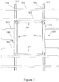
- the installation frame 100 is illustrated in perspective in Figs. 1 and 2 .
- the installation frame 100 comprises two side parts 130, a bottom part 120, and a top part 140.
- the parts 130, 120, 140 are connected to form a rectangular frame.
- the side parts 130 comprise locking elements 133, which are in Fig. 1 in a locking position and in Fig. 2 in a release position.
- Figs. 3 and 4 are detailed views of the lower left corner 100a of the installation frame 100 in a disassembled condition and shows ends of the side part 130 and the bottom part 120, wherein the side part 130 includes the locking element 133, a protrusion 135, and a longitudinal side member 131, and wherein the bottom part 120 includes a longitudinal bottom member 121 and an abutment element 123.
- the locking element 133 is shown in the release position.
- the locking element 133 is a resilient element that is shaped such that it has a spring effect.
- the abutment element 123 comprises a protruding region providing an abutment 123a for the side part 130, as it will be explained below, and a lock-enabling region with a bump 123b.
- the protrusion 135 comprises a first flat part 135a extending from an end face 131a of the longitudinal side member 131 generally in parallel with a general plane of the installation frame 100. At an extreme end relative to the end face 131a the protrusion is bent to provide a flange portion 135b extending perpendicular to a longitudinal direction A of the side part 130 (see Fig. 6 ).
- the longitudinal side member 131 has a general L-shape in cross-section providing a lateral part 131b with a reduced height h (see Fig. 5 ). The remaining part of the longitudinal side member 131 is extending beyond the height h by an additional height H (see Fig. 5 ).
- the bottom part 120 further comprises a shallow recess 125 and a groove 127, where the groove 127 is adjacent to the recess 125.
- the recess 125 provides an edge, which per se provides a second abutment 125a for the side part 130 i.e. for the first flat part 135a of the protrusion 135 thereof.
- corner diagonally opposite the corner 100a is constructed similar to the corner 100a whereas the two other corners of the installation frame 100 are mirror inverted relative to the corner 100a.
- the protrusion 135 is inserted into the recess 125 and the groove 127, the first flat part 135a being accommodated in the recess 125 and the flange portion 135b being accommodated in the groove 127.
- the protrusion 135, the recess 125, and especially the groove 127 provide a sliding guide allowing the side parts 130 to be shifted in a longitudinal direction B of the bottom part 120 and the top part 140 within limits determined by the first abutment 123a and the second abutment 125a, the latter being assisted by the inwardly end of the groove 127 which provides a limit for the inward lateral movement of the flange portion 135b of the protrusion and thereby for the side part 130.
- the first abutment 123a protruding from the longitudinal bottom member 121 provides a limit of the outward lateral movement of the side part 130.
- the longitudinal side members 131 are abutting on the first abutments 123a the side parts 130 being positioned in defined distal positions relative to each other. From this position the side parts 130 may be shifted towards each other until the protrusions 135 abut on the second abutment 125a and the inwardly end of the grooves 127. Thereby the side parts 130 are brought to a defined proximal position relative to each other.
- Fig. 6 shows the installation frame 100 with the side parts 130 in the proximal position.
- Fig. 5 shows the lower left corner 100a comprising the longitudinal bottom member 121, the abutment element 123 with the first abutment 123a and the bump 123b, the longitudinal side member 131, the protrusion 135 and the groove 127 accommodating the flange portion 135b.
- the locking element 133 is shown in the release position in which it does not engage with the abutment element 123.
- the locking element 133 is in the locking position shown in e.g. Fig. 1 .
- the locking element 133 due to the spring effect urges the longitudinal bottom element 121 against the adjacent end face 131a of the longitudinal side element 131 thereby providing a frictional engagement between the longitudinal bottom element 121 and the longitudinal side element 131 which lock the longitudinal side element 131 in its position along the slide guide provided by the protrusion 135 and the groove 127, etc.
- the side part 130 may be locked in any position relative to the bottom part 120 and the top part 140 between the proximal position and the distal position, these two positions included.
- Fig. 7 illustrates a mounted position of the installation frame 100 in a roof structure known per se, where the roof structure comprises a plurality of horizontal battens 302, 303, and a plurality of rafters 301 overlaid by counter battens 304.
- the procedure for placing the installation frame 100 in the position shown in Fig. 7 is as follows: While the battens 303 are intact like the battens 302 and the counter battens 304 are also intact substantially in the extent the rafters 301, the installation frame 100 with the side parts 130 in the proximal position, as shown in Fig. 6 , is placed upon the battens 303 to be used as a jig to mark where the battens 303 are to be cut to provide an opening for installing the installation frame 100. At this time the locking elements 133 are preferably in their locking positions to assure that the side parts 130 remain in their proximal position during marking.
- the installation frame 100 is then removed and the battens 303 and counter battens 304 are cut, and the batten parts and counter batten parts between the cuts are removed.
- the installation frame 100 is preplaced, but now to rest against the rafters 301. It is noted that the installation frame 100 with the side parts 130 in their proximal position will fit between the cut ends of the battens 303 because the installation frame 100 has been used a jig.
- the locking elements 133 are now rotated to their release position and the side parts 130 of the installation frame 100 are shifted outwards into their distal position. The lateral parts 131b of the side parts 130 are thereby slid beneath the cut ends of the battens 303 for the installation frame 100 to assume the position shown in Fig. 7 .
- the locking elements may now be put back into the locking position to ensure that the side parts 130 remain in the distal position.
- the height h of the lateral parts 131b is similar to the thickness of the counter battens 304 and thus the cut ends of the battens 303 rest on the lateral parts 131b. Further the height H is similar to the thickness of the battens 302, 303 and accordingly the upper surface of the installation frame 100 is substantially flush with a surface defined by the upper surfaces of the battens 302, 303.
- the installation frame is fastened into place e.g. by screws inserted through the bottom part 120, the top part 140, and the side parts 130 into the rafters 301, and the cut ends of the battens 303 may be attached, e.g. by screws, to the lateral parts 131b to provide support for the cut batten ends.
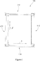
- an insulation frame 200 is provided to be inserted between the installation frame 100 and a window (not shown) to be mounted or installed in the roof construction by means of the installation frame 100
- Fig. 8 shows the insulation frame 200 comprising a plurality of attachment features or hooks 201 arranged along the circumference of the insulation frame 200.
- Fig. 9 shows the installation frame 100 and the insulation frame 200 where the insulation frame 200 has been inserted into in the installation frame 100. This should be done at the time when the installation frame is installed and fixed in the roof construction as described above.
- the insulating frame 200 in the installation frame 100 the latter comprises an upper groove 137 in upper surfaces of the bottom part 120, the side parts 130, and the top part 140, see e. g. Figs 1 and 2 and especially Fig. 10 , which shows the cross-section indicated by arrow X in Fig. 9 of one of the side parts 130 and the adjacent part of the insulating frame 200.
- Fig. 10 is seen in the longitudinal direction A of the side part 130.
- Fig. 10 illustrates a cross-sectional view of the insulation frame 200 mounted in the installation frame 100, where the attachment feature or hook 201 of the insulation frame 200 fits in the groove 137 located in the longitudinal side member 131 of the side part 130.
- the insulation frame 200 is attached similarly all along the circumference of the insulation frame 200.
- the insulation frame 200 further comprises a window abutment portion 202, providing an abutment for a window inserted within the insulation frame as is will be appreciated by the skilled person.
- the optional insulation frame as illustrated in Fig. 8 can be attached to the installation frame as illustrated in Fig. 9 and a roof window can be inserted herein. Subsequently the window may be fixed by means of bracket fastened to a frame of the window in a manner known per se. These brackets may extend across the insulation frame 200 and the installation frame 100 to be fixed to the battens. e.g. by means of screws, but in an embodiment such brackets are fixed to the installation frame 100 proper, e.g. by means of screws.
- top, bottom and side are used to indicate the intended position of different parts in the mounted position even though these parts may be located differently during for example storage and transportation or prior to assembly of the insulating frame.
- inward and outward are used to indicate that something is facing the center of the installation frame or the outer edge of the installation frame.
- the sliding function of the side parts can be achieved by other means than shown in this embodiment.
- the protrusion be a part of the member, or any other means of translating two parts in a prismatic joint. Further shifting the side parts between their mutual distal and proximal positions might be obtained by shifting only one of the side parts relative to the bottom part and top part or by shifting the respective parts only at two diagonally opposite corners whereby also the bottom part and the top part would be shifted relative to each other in their longitudinal direction B.
- the invention offers several advantages over different prior art solutions. Due to the shiftable side parts the battens may be cut to a required minimum for providing space for a window to be installed including the installation frame and any insulation frame or frames. This is a major advantage e.g. when installing a window in an existing roof e.g. at a place where a window has not previously been present because a minimum of the roof covering such as tiles need to be removed and the battens supporting such tiles are disturbed to the least possible degree and need e.g. not be loosened and lifted to allow mounting of the installation frame.
Landscapes
- Engineering & Computer Science (AREA)
- Civil Engineering (AREA)
- Structural Engineering (AREA)
- Architecture (AREA)
- Roof Covering Using Slabs Or Stiff Sheets (AREA)
- Wing Frames And Configurations (AREA)
Claims (10)
- Cadre d'installation (100) pour une fenêtre de toit destiné à être installé dans une structure de toit comprenant des lattes (302, 303), ledit cadre d'installation (100) comprenant une partie supérieure (140), une partie inférieure (120) et deux parties de côté (130), les parties de côté (130) pouvant être reliées à la partie supérieure (140) et à la partie inférieure (120) au niveau de leurs extrémités pour former le cadre d'installation (100) comme un cadre rectangulaire, au moins une des parties de côté (130) pouvant être reliée de manière mobile à la partie supérieure (140) et/ou à la partie inférieure (120) pour que lesdites parties de côté (130) puissent être décalées par un mouvement latéral au moins relatif en se rapprochant et en s'éloignant l'une de l'autre pour que lesdites parties de côté (130) prennent respectivement une position proximale définie et une position distale définie l'une par rapport à l'autre,
un élément de verrouillage (133) étant mobile entre une position de verrouillage, dans laquelle il verrouille ladite au moins une partie de côté par rapport à la partie supérieure (140) et/ou à la partie inférieure (120), et une position de libération dans laquelle il libère ladite au moins une partie de côté pour qu'elle soit décalée par rapport à la partie supérieure (140) et/ou à la partie inférieure (120),
caractérisé en ce que ledit élément de verrouillage (133) est un élément élastique poussant dans sa position de verrouillage ladite au moins une partie de côté et la partie supérieure (140) et/ou la partie inférieure (120) l'une contre l'autre dans une mise en prise par friction. - Cadre d'installation (100) selon la revendication 1, caractérisé en ce que les parties de côté (130) comprennent des parties latérales (131b) conçues pour être positionnées sous les extrémités coupées des lattes.
- Cadre d'installation (100) selon la revendication 1 ou 2, caractérisé en ce que les parties de côté (130) comprennent un élément de côté longitudinal (131) avec une section transversale en forme générale de L fournissant une partie latérale (131b) avec une hauteur réduite (h), une partie restante de l'élément de côté longitudinal (131) s'étendant au-delà de ladite hauteur (h) sur une hauteur supplémentaire (H).
- Cadre d'installation (100) selon l'une quelconque des revendications 1 à 3, caractérisé en ce que ladite au moins une partie de côté (130) est conçue pour être verrouillée par rapport à la partie supérieure (140) et/ou la partie inférieure (120) pour que les parties de côté (130) soient verrouillées dans ladite position proximale et/ou ladite position distale.
- Cadre d'installation (100) selon l'une quelconque des revendications 1 à 4, caractérisé en ce que ladite au moins une partie de côté est reliée à la partie supérieure (140) et/ou à la partie inférieure (120) par un guide coulissant permettant à la partie de côté d'être décalée dans une direction longitudinale de la partie supérieure (140) et de la partie inférieure (120).
- Cadre d'installation (100) selon la revendication 5, caractérisé en ce que ledit guide coulissant comprend une saillie s'étendant à partir de l'une des parties de côté et de la partie supérieure (140) et/ou de la partie inférieure (120), ladite saillie s'étendant, lorsque le cadre d'installation (100) est assemblé, dans une rainure (127) dans l'autre de la partie de côté et de la partie supérieure (140) et/ou de la partie inférieure (120).
- Cadre d'installation (100) selon l'une quelconque des revendications précédentes, caractérisé par au moins une butée (123) limitant le mouvement latéral de ladite au moins une partie de côté par rapport à la partie supérieure (140) et/ou la partie inférieure (120).
- Kit de pièces comprenant une fenêtre de toit, un cadre d'installation (100) selon l'une quelconque des revendications 1 à 7, et éventuellement un cadre d'isolation supplémentaire (200) à insérer entre le cadre d'installation (100) et la fenêtre de toit.
- Procédé d'installation d'un cadre d'installation (100) selon l'une quelconque des revendications 1 à 7, caractérisé par l'assemblage de la partie supérieure (140), de la partie inférieure (120) et des parties de côté (130) pour constituer le cadre rectangulaire, les parties de côté (130) étant décalées l'une vers l'autre, le positionnement du cadre ainsi assemblé sur une structure de toit comprenant des lattes (302, 303), le marquage et la découpe des lattes (303) sur les côtés extérieurs des parties de côté (130), l'enlèvement des parties découpées des lattes (303), le repositionnement du cadre à la place des parties découpées des lattes (303), le décalage des parties de côté (130) à l'opposé l'une de l'autre pour que les parties latérales des parties de côté (130) soient positionnées sous les extrémités découpées restantes des lattes (303).
- Procédé selon la revendication 9 d'installation d'un cadre d'installation (100) selon la revendication 4, caractérisé par le verrouillage de l'au moins une partie de côté sur la partie supérieure (140) et/ou la partie inférieure (120) après avoir assemblé la partie supérieure (140), la partie inférieure (120) et les parties de côté (130) pour fournir le cadre rectangulaire, les parties de côté (130) étant décalées l'une vers l'autre, et le déverrouillage des parties de côté de la partie supérieure (140) et/ou de la partie inférieure (120) avant de décaler les parties de côté (130) à l'opposé l'une de l'autre pour que les parties latérales des parties de côté (130) soient positionnées sous les extrémités coupées restantes des lattes (303).
Priority Applications (1)
| Application Number | Priority Date | Filing Date | Title |
|---|---|---|---|
| PL17204366T PL3330451T3 (pl) | 2016-12-05 | 2017-11-29 | Ościeżnica do okna dachowego, zestaw części obejmujący taką ościeżnicę oraz sposób montażu ościeżnicy |
Applications Claiming Priority (1)
| Application Number | Priority Date | Filing Date | Title |
|---|---|---|---|
| DKPA201670962A DK179323B1 (en) | 2016-12-05 | 2016-12-05 | An installation frame for a roof window, a kit of parts comprising such installation frame, and a method of installing the installation frame |
Publications (2)
| Publication Number | Publication Date |
|---|---|
| EP3330451A1 EP3330451A1 (fr) | 2018-06-06 |
| EP3330451B1 true EP3330451B1 (fr) | 2020-12-23 |
Family
ID=62017670
Family Applications (1)
| Application Number | Title | Priority Date | Filing Date |
|---|---|---|---|
| EP17204366.3A Active EP3330451B1 (fr) | 2016-12-05 | 2017-11-29 | Cadre d'installation d'une fenêtre de toit, kit de pièces comprenant un tel cadre d'installation et procédé d'installation du cadre d'installation |
Country Status (5)
| Country | Link |
|---|---|
| EP (1) | EP3330451B1 (fr) |
| CN (1) | CN207959648U (fr) |
| DK (1) | DK179323B1 (fr) |
| HU (1) | HUE052414T2 (fr) |
| PL (1) | PL3330451T3 (fr) |
Cited By (1)
| Publication number | Priority date | Publication date | Assignee | Title |
|---|---|---|---|---|
| DE102020209060A1 (de) | 2020-07-20 | 2022-01-20 | Roto Frank Dachsystem-Technologie GmbH | Einbaurahmen zur Montage eines Dachflächenfensters, Dachfensteranordnung, Dachanordnung sowie Verfahren zum Montieren eines Dachflächenfensters |
Families Citing this family (1)
| Publication number | Priority date | Publication date | Assignee | Title |
|---|---|---|---|---|
| EP3656943A1 (fr) | 2018-11-20 | 2020-05-27 | VKR Holding A/S | Procédé d'installation d'un cadre d'isolation dans une fenêtre de toit, cadre d'isolation pour utilisation dans celle-ci et kit d'installation |
Family Cites Families (9)
| Publication number | Priority date | Publication date | Assignee | Title |
|---|---|---|---|---|
| US4924649A (en) * | 1989-07-13 | 1990-05-15 | Innovative Building Products, Inc. | Corner assembly for a skylight frame |
| AU3166697A (en) * | 1997-01-14 | 1998-08-07 | Velux Industri A/S | An insulation and installation frame for a skylight window and a method for in stallation of a skylight window by use of such a frame |
| DK199900873A (da) * | 1999-06-18 | 2001-04-02 | Vkr Holding As | Isoleringsramme for et ovenlysvindue |
| US6804918B2 (en) * | 2001-01-19 | 2004-10-19 | Vkr Holding A/S | Roof window assembly comprising a window component and an external screening accessory |
| DE202006014016U1 (de) * | 2006-09-08 | 2006-12-28 | Eternit Flachdach Gmbh | Dachelement |
| DE102010027419A1 (de) * | 2010-07-09 | 2012-01-12 | Roto Frank Ag | Dachfensteranordnung, Dachkonstruktion und Verfahren zur Montage eines Dachfensters |
| PL218383B1 (pl) * | 2011-02-14 | 2014-11-28 | Fakro Pp Spółka Z Ograniczoną Odpowiedzialnością | Zestaw okienny dla dachu łukowego |
| DK177645B1 (en) * | 2012-06-19 | 2014-01-27 | Vkr Holding As | An insulating frame for a roof window and a method of mounting a roof window |
| PL2700781T3 (pl) * | 2012-08-22 | 2018-07-31 | Vkr Holding A/S | Zespół okładziny okiennej mający ulepszony łącznik narożny |
-
2016
- 2016-12-05 DK DKPA201670962A patent/DK179323B1/en active
-
2017
- 2017-11-29 HU HUE17204366A patent/HUE052414T2/hu unknown
- 2017-11-29 EP EP17204366.3A patent/EP3330451B1/fr active Active
- 2017-11-29 PL PL17204366T patent/PL3330451T3/pl unknown
- 2017-12-05 CN CN201721677298.5U patent/CN207959648U/zh active Active
Non-Patent Citations (1)
| Title |
|---|
| None * |
Cited By (1)
| Publication number | Priority date | Publication date | Assignee | Title |
|---|---|---|---|---|
| DE102020209060A1 (de) | 2020-07-20 | 2022-01-20 | Roto Frank Dachsystem-Technologie GmbH | Einbaurahmen zur Montage eines Dachflächenfensters, Dachfensteranordnung, Dachanordnung sowie Verfahren zum Montieren eines Dachflächenfensters |
Also Published As
| Publication number | Publication date |
|---|---|
| PL3330451T3 (pl) | 2021-05-31 |
| DK179323B1 (en) | 2018-04-30 |
| EP3330451A1 (fr) | 2018-06-06 |
| DK201670962A1 (en) | 2018-04-30 |
| HUE052414T2 (hu) | 2021-04-28 |
| CN207959648U (zh) | 2018-10-12 |
Similar Documents
| Publication | Publication Date | Title |
|---|---|---|
| EP3330451B1 (fr) | Cadre d'installation d'une fenêtre de toit, kit de pièces comprenant un tel cadre d'installation et procédé d'installation du cadre d'installation | |
| EP2318609B1 (fr) | Fenêtre de toit montée sur pan comportant un composant de parement unitaire | |
| US10889994B1 (en) | Step clip fastening system and method | |
| US10316583B2 (en) | Screening arrangement | |
| US8919417B2 (en) | Head rail of window covering and lid fastener | |
| US7178300B2 (en) | Latch-type tile mounting system | |
| CA3084539C (fr) | Systeme et procede de clip de fixation de marchepied | |
| PL226077B1 (pl) | Zespol mocujacy do montazu elementu oslonowego skrzydla okna dachowego | |
| JP6831076B2 (ja) | 建具 | |
| JP2941770B1 (ja) | ピボットヒンジ | |
| JP3988872B2 (ja) | 嵌め殺し窓 | |
| JP6156884B2 (ja) | 基礎水切取付具 | |
| EP2011951B1 (fr) | Support avec un dispositif de couverture | |
| JPH0720267Y2 (ja) | パネル材の取付構造 | |
| JP6529890B2 (ja) | 笠木を備えた壁構造 | |
| JP4899640B2 (ja) | 雪止め金具 | |
| JP2501148Y2 (ja) | 換気シャッタ付鼻隠の取り付け構造 | |
| KR0127436Y1 (ko) | 창문용 정지장치 | |
| JP2005307656A (ja) | 外装パネルの胴縁への取付構造。 | |
| JPH0566191U (ja) | 引戸用レール付き下枠と竪枠との連結部構造 | |
| JPH0235992Y2 (fr) | ||
| JPH0452388Y2 (fr) | ||
| JPH09177251A (ja) | 安定駒利用の耐震・耐風瓦葺工法 | |
| NZ544143A (en) | Ladder | |
| JPH10339045A (ja) | 浴槽ユニットの天井パネル取付構造及び取付方法 |
Legal Events
| Date | Code | Title | Description |
|---|---|---|---|
| PUAI | Public reference made under article 153(3) epc to a published international application that has entered the european phase |
Free format text: ORIGINAL CODE: 0009012 |
|
| STAA | Information on the status of an ep patent application or granted ep patent |
Free format text: STATUS: THE APPLICATION HAS BEEN PUBLISHED |
|
| AK | Designated contracting states |
Kind code of ref document: A1 Designated state(s): AL AT BE BG CH CY CZ DE DK EE ES FI FR GB GR HR HU IE IS IT LI LT LU LV MC MK MT NL NO PL PT RO RS SE SI SK SM TR |
|
| AX | Request for extension of the european patent |
Extension state: BA ME |
|
| STAA | Information on the status of an ep patent application or granted ep patent |
Free format text: STATUS: REQUEST FOR EXAMINATION WAS MADE |
|
| 17P | Request for examination filed |
Effective date: 20181204 |
|
| RBV | Designated contracting states (corrected) |
Designated state(s): AL AT BE BG CH CY CZ DE DK EE ES FI FR GB GR HR HU IE IS IT LI LT LU LV MC MK MT NL NO PL PT RO RS SE SI SK SM TR |
|
| STAA | Information on the status of an ep patent application or granted ep patent |
Free format text: STATUS: EXAMINATION IS IN PROGRESS |
|
| 17Q | First examination report despatched |
Effective date: 20200122 |
|
| GRAP | Despatch of communication of intention to grant a patent |
Free format text: ORIGINAL CODE: EPIDOSNIGR1 |
|
| STAA | Information on the status of an ep patent application or granted ep patent |
Free format text: STATUS: GRANT OF PATENT IS INTENDED |
|
| RIC1 | Information provided on ipc code assigned before grant |
Ipc: E06B 3/968 20060101ALN20200616BHEP Ipc: E04D 13/03 20060101AFI20200616BHEP Ipc: E06B 3/96 20060101ALI20200616BHEP Ipc: E06B 3/964 20060101ALI20200616BHEP Ipc: E06B 3/984 20060101ALI20200616BHEP |
|
| INTG | Intention to grant announced |
Effective date: 20200703 |
|
| GRAS | Grant fee paid |
Free format text: ORIGINAL CODE: EPIDOSNIGR3 |
|
| GRAA | (expected) grant |
Free format text: ORIGINAL CODE: 0009210 |
|
| STAA | Information on the status of an ep patent application or granted ep patent |
Free format text: STATUS: THE PATENT HAS BEEN GRANTED |
|
| AK | Designated contracting states |
Kind code of ref document: B1 Designated state(s): AL AT BE BG CH CY CZ DE DK EE ES FI FR GB GR HR HU IE IS IT LI LT LU LV MC MK MT NL NO PL PT RO RS SE SI SK SM TR |
|
| REG | Reference to a national code |
Ref country code: GB Ref legal event code: FG4D |
|
| REG | Reference to a national code |
Ref country code: DE Ref legal event code: R096 Ref document number: 602017029935 Country of ref document: DE |
|
| REG | Reference to a national code |
Ref country code: AT Ref legal event code: REF Ref document number: 1347873 Country of ref document: AT Kind code of ref document: T Effective date: 20210115 |
|
| REG | Reference to a national code |
Ref country code: IE Ref legal event code: FG4D |
|
| REG | Reference to a national code |
Ref country code: NL Ref legal event code: FP |
|
| REG | Reference to a national code |
Ref country code: HU Ref legal event code: AG4A Ref document number: E052414 Country of ref document: HU |
|
| PG25 | Lapsed in a contracting state [announced via postgrant information from national office to epo] |
Ref country code: GR Free format text: LAPSE BECAUSE OF FAILURE TO SUBMIT A TRANSLATION OF THE DESCRIPTION OR TO PAY THE FEE WITHIN THE PRESCRIBED TIME-LIMIT Effective date: 20210324 Ref country code: FI Free format text: LAPSE BECAUSE OF FAILURE TO SUBMIT A TRANSLATION OF THE DESCRIPTION OR TO PAY THE FEE WITHIN THE PRESCRIBED TIME-LIMIT Effective date: 20201223 Ref country code: RS Free format text: LAPSE BECAUSE OF FAILURE TO SUBMIT A TRANSLATION OF THE DESCRIPTION OR TO PAY THE FEE WITHIN THE PRESCRIBED TIME-LIMIT Effective date: 20201223 Ref country code: NO Free format text: LAPSE BECAUSE OF FAILURE TO SUBMIT A TRANSLATION OF THE DESCRIPTION OR TO PAY THE FEE WITHIN THE PRESCRIBED TIME-LIMIT Effective date: 20210323 |
|
| PG25 | Lapsed in a contracting state [announced via postgrant information from national office to epo] |
Ref country code: LV Free format text: LAPSE BECAUSE OF FAILURE TO SUBMIT A TRANSLATION OF THE DESCRIPTION OR TO PAY THE FEE WITHIN THE PRESCRIBED TIME-LIMIT Effective date: 20201223 Ref country code: BG Free format text: LAPSE BECAUSE OF FAILURE TO SUBMIT A TRANSLATION OF THE DESCRIPTION OR TO PAY THE FEE WITHIN THE PRESCRIBED TIME-LIMIT Effective date: 20210323 Ref country code: SE Free format text: LAPSE BECAUSE OF FAILURE TO SUBMIT A TRANSLATION OF THE DESCRIPTION OR TO PAY THE FEE WITHIN THE PRESCRIBED TIME-LIMIT Effective date: 20201223 |
|
| PG25 | Lapsed in a contracting state [announced via postgrant information from national office to epo] |
Ref country code: HR Free format text: LAPSE BECAUSE OF FAILURE TO SUBMIT A TRANSLATION OF THE DESCRIPTION OR TO PAY THE FEE WITHIN THE PRESCRIBED TIME-LIMIT Effective date: 20201223 |
|
| REG | Reference to a national code |
Ref country code: LT Ref legal event code: MG9D |
|
| PG25 | Lapsed in a contracting state [announced via postgrant information from national office to epo] |
Ref country code: SK Free format text: LAPSE BECAUSE OF FAILURE TO SUBMIT A TRANSLATION OF THE DESCRIPTION OR TO PAY THE FEE WITHIN THE PRESCRIBED TIME-LIMIT Effective date: 20201223 Ref country code: PT Free format text: LAPSE BECAUSE OF FAILURE TO SUBMIT A TRANSLATION OF THE DESCRIPTION OR TO PAY THE FEE WITHIN THE PRESCRIBED TIME-LIMIT Effective date: 20210423 Ref country code: RO Free format text: LAPSE BECAUSE OF FAILURE TO SUBMIT A TRANSLATION OF THE DESCRIPTION OR TO PAY THE FEE WITHIN THE PRESCRIBED TIME-LIMIT Effective date: 20201223 Ref country code: SM Free format text: LAPSE BECAUSE OF FAILURE TO SUBMIT A TRANSLATION OF THE DESCRIPTION OR TO PAY THE FEE WITHIN THE PRESCRIBED TIME-LIMIT Effective date: 20201223 Ref country code: EE Free format text: LAPSE BECAUSE OF FAILURE TO SUBMIT A TRANSLATION OF THE DESCRIPTION OR TO PAY THE FEE WITHIN THE PRESCRIBED TIME-LIMIT Effective date: 20201223 Ref country code: LT Free format text: LAPSE BECAUSE OF FAILURE TO SUBMIT A TRANSLATION OF THE DESCRIPTION OR TO PAY THE FEE WITHIN THE PRESCRIBED TIME-LIMIT Effective date: 20201223 |
|
| REG | Reference to a national code |
Ref country code: DE Ref legal event code: R097 Ref document number: 602017029935 Country of ref document: DE |
|
| PG25 | Lapsed in a contracting state [announced via postgrant information from national office to epo] |
Ref country code: IS Free format text: LAPSE BECAUSE OF FAILURE TO SUBMIT A TRANSLATION OF THE DESCRIPTION OR TO PAY THE FEE WITHIN THE PRESCRIBED TIME-LIMIT Effective date: 20210423 |
|
| PG25 | Lapsed in a contracting state [announced via postgrant information from national office to epo] |
Ref country code: AL Free format text: LAPSE BECAUSE OF FAILURE TO SUBMIT A TRANSLATION OF THE DESCRIPTION OR TO PAY THE FEE WITHIN THE PRESCRIBED TIME-LIMIT Effective date: 20201223 |
|
| PLBE | No opposition filed within time limit |
Free format text: ORIGINAL CODE: 0009261 |
|
| STAA | Information on the status of an ep patent application or granted ep patent |
Free format text: STATUS: NO OPPOSITION FILED WITHIN TIME LIMIT |
|
| PG25 | Lapsed in a contracting state [announced via postgrant information from national office to epo] |
Ref country code: DK Free format text: LAPSE BECAUSE OF FAILURE TO SUBMIT A TRANSLATION OF THE DESCRIPTION OR TO PAY THE FEE WITHIN THE PRESCRIBED TIME-LIMIT Effective date: 20201223 |
|
| 26N | No opposition filed |
Effective date: 20210924 |
|
| PG25 | Lapsed in a contracting state [announced via postgrant information from national office to epo] |
Ref country code: ES Free format text: LAPSE BECAUSE OF FAILURE TO SUBMIT A TRANSLATION OF THE DESCRIPTION OR TO PAY THE FEE WITHIN THE PRESCRIBED TIME-LIMIT Effective date: 20201223 |
|
| PG25 | Lapsed in a contracting state [announced via postgrant information from national office to epo] |
Ref country code: SI Free format text: LAPSE BECAUSE OF FAILURE TO SUBMIT A TRANSLATION OF THE DESCRIPTION OR TO PAY THE FEE WITHIN THE PRESCRIBED TIME-LIMIT Effective date: 20201223 |
|
| PG25 | Lapsed in a contracting state [announced via postgrant information from national office to epo] |
Ref country code: IS Free format text: LAPSE BECAUSE OF FAILURE TO SUBMIT A TRANSLATION OF THE DESCRIPTION OR TO PAY THE FEE WITHIN THE PRESCRIBED TIME-LIMIT Effective date: 20210423 |
|
| PG25 | Lapsed in a contracting state [announced via postgrant information from national office to epo] |
Ref country code: MC Free format text: LAPSE BECAUSE OF FAILURE TO SUBMIT A TRANSLATION OF THE DESCRIPTION OR TO PAY THE FEE WITHIN THE PRESCRIBED TIME-LIMIT Effective date: 20201223 |
|
| PG25 | Lapsed in a contracting state [announced via postgrant information from national office to epo] |
Ref country code: LU Free format text: LAPSE BECAUSE OF NON-PAYMENT OF DUE FEES Effective date: 20211129 |
|
| PG25 | Lapsed in a contracting state [announced via postgrant information from national office to epo] |
Ref country code: IE Free format text: LAPSE BECAUSE OF NON-PAYMENT OF DUE FEES Effective date: 20211129 |
|
| REG | Reference to a national code |
Ref country code: AT Ref legal event code: UEP Ref document number: 1347873 Country of ref document: AT Kind code of ref document: T Effective date: 20201223 |
|
| PG25 | Lapsed in a contracting state [announced via postgrant information from national office to epo] |
Ref country code: CY Free format text: LAPSE BECAUSE OF FAILURE TO SUBMIT A TRANSLATION OF THE DESCRIPTION OR TO PAY THE FEE WITHIN THE PRESCRIBED TIME-LIMIT Effective date: 20201223 |
|
| PGFP | Annual fee paid to national office [announced via postgrant information from national office to epo] |
Ref country code: NL Payment date: 20231013 Year of fee payment: 7 |
|
| PGFP | Annual fee paid to national office [announced via postgrant information from national office to epo] |
Ref country code: GB Payment date: 20231006 Year of fee payment: 7 |
|
| PGFP | Annual fee paid to national office [announced via postgrant information from national office to epo] |
Ref country code: IT Payment date: 20231010 Year of fee payment: 7 Ref country code: HU Payment date: 20231019 Year of fee payment: 7 Ref country code: FR Payment date: 20231024 Year of fee payment: 7 Ref country code: DE Payment date: 20231003 Year of fee payment: 7 Ref country code: CZ Payment date: 20231026 Year of fee payment: 7 Ref country code: CH Payment date: 20231201 Year of fee payment: 7 Ref country code: AT Payment date: 20231025 Year of fee payment: 7 |
|
| PGFP | Annual fee paid to national office [announced via postgrant information from national office to epo] |
Ref country code: PL Payment date: 20231016 Year of fee payment: 7 Ref country code: BE Payment date: 20231016 Year of fee payment: 7 |
|
| PG25 | Lapsed in a contracting state [announced via postgrant information from national office to epo] |
Ref country code: MK Free format text: LAPSE BECAUSE OF FAILURE TO SUBMIT A TRANSLATION OF THE DESCRIPTION OR TO PAY THE FEE WITHIN THE PRESCRIBED TIME-LIMIT Effective date: 20201223 |