EP3329985A1 - Verfahren zur herstellung einer umkehrosmose-membran - Google Patents
Verfahren zur herstellung einer umkehrosmose-membran Download PDFInfo
- Publication number
- EP3329985A1 EP3329985A1 EP16830587.8A EP16830587A EP3329985A1 EP 3329985 A1 EP3329985 A1 EP 3329985A1 EP 16830587 A EP16830587 A EP 16830587A EP 3329985 A1 EP3329985 A1 EP 3329985A1
- Authority
- EP
- European Patent Office
- Prior art keywords
- membrane
- carbon
- reverse osmosis
- forming
- coating
- Prior art date
- Legal status (The legal status is an assumption and is not a legal conclusion. Google has not performed a legal analysis and makes no representation as to the accuracy of the status listed.)
- Granted
Links
Images














Classifications
-
- B—PERFORMING OPERATIONS; TRANSPORTING
- B01—PHYSICAL OR CHEMICAL PROCESSES OR APPARATUS IN GENERAL
- B01D—SEPARATION
- B01D69/00—Semi-permeable membranes for separation processes or apparatus characterised by their form, structure or properties; Manufacturing processes specially adapted therefor
- B01D69/12—Composite membranes; Ultra-thin membranes
-
- B—PERFORMING OPERATIONS; TRANSPORTING
- B01—PHYSICAL OR CHEMICAL PROCESSES OR APPARATUS IN GENERAL
- B01D—SEPARATION
- B01D61/00—Processes of separation using semi-permeable membranes, e.g. dialysis, osmosis or ultrafiltration; Apparatus, accessories or auxiliary operations specially adapted therefor
- B01D61/02—Reverse osmosis; Hyperfiltration ; Nanofiltration
- B01D61/025—Reverse osmosis; Hyperfiltration
-
- B—PERFORMING OPERATIONS; TRANSPORTING
- B01—PHYSICAL OR CHEMICAL PROCESSES OR APPARATUS IN GENERAL
- B01D—SEPARATION
- B01D67/00—Processes specially adapted for manufacturing semi-permeable membranes for separation processes or apparatus
- B01D67/0039—Inorganic membrane manufacture
- B01D67/0072—Inorganic membrane manufacture by deposition from the gaseous phase, e.g. sputtering, CVD, PVD
-
- B—PERFORMING OPERATIONS; TRANSPORTING
- B01—PHYSICAL OR CHEMICAL PROCESSES OR APPARATUS IN GENERAL
- B01D—SEPARATION
- B01D69/00—Semi-permeable membranes for separation processes or apparatus characterised by their form, structure or properties; Manufacturing processes specially adapted therefor
- B01D69/10—Supported membranes; Membrane supports
- B01D69/106—Membranes in the pores of a support, e.g. polymerized in the pores or voids
-
- B—PERFORMING OPERATIONS; TRANSPORTING
- B01—PHYSICAL OR CHEMICAL PROCESSES OR APPARATUS IN GENERAL
- B01D—SEPARATION
- B01D69/00—Semi-permeable membranes for separation processes or apparatus characterised by their form, structure or properties; Manufacturing processes specially adapted therefor
- B01D69/10—Supported membranes; Membrane supports
- B01D69/107—Organic support material
-
- B—PERFORMING OPERATIONS; TRANSPORTING
- B01—PHYSICAL OR CHEMICAL PROCESSES OR APPARATUS IN GENERAL
- B01D—SEPARATION
- B01D69/00—Semi-permeable membranes for separation processes or apparatus characterised by their form, structure or properties; Manufacturing processes specially adapted therefor
- B01D69/10—Supported membranes; Membrane supports
- B01D69/107—Organic support material
- B01D69/1071—Woven, non-woven or net mesh
-
- B—PERFORMING OPERATIONS; TRANSPORTING
- B01—PHYSICAL OR CHEMICAL PROCESSES OR APPARATUS IN GENERAL
- B01D—SEPARATION
- B01D71/00—Semi-permeable membranes for separation processes or apparatus characterised by the material; Manufacturing processes specially adapted therefor
- B01D71/02—Inorganic material
- B01D71/021—Carbon
-
- B—PERFORMING OPERATIONS; TRANSPORTING
- B01—PHYSICAL OR CHEMICAL PROCESSES OR APPARATUS IN GENERAL
- B01D—SEPARATION
- B01D53/00—Separation of gases or vapours; Recovering vapours of volatile solvents from gases; Chemical or biological purification of waste gases, e.g. engine exhaust gases, smoke, fumes, flue gases, aerosols
- B01D53/22—Separation of gases or vapours; Recovering vapours of volatile solvents from gases; Chemical or biological purification of waste gases, e.g. engine exhaust gases, smoke, fumes, flue gases, aerosols by diffusion
- B01D53/228—Separation of gases or vapours; Recovering vapours of volatile solvents from gases; Chemical or biological purification of waste gases, e.g. engine exhaust gases, smoke, fumes, flue gases, aerosols by diffusion characterised by specific membranes
Definitions
- the present invention relates to a method of forming a reverse osmosis membrane.
- porous carbon membrane As an active layer in a filtration membrane.
- the porous carbon membrane has superior durability and the like to those of, for example, polymer membranes such as polyamide based membranes, which were the conventional mainstream as the active layer. In recent years, practical use of the porous carbon membrane is expected.
- Patent Document 1 discloses that a porous carbon membrane formed by a plasma chemical vapor deposition (CVD) is used as the active layer, in which hydrocarbon gas such as acetylene is used as a carbon source.
- the porous carbon membrane has a plurality of pores of about several nanometers, the pores being provided through the porous carbon membrane in the thickness direction.
- the impermeable rate for sodium chloride (the concentration: 34 mM) is 68.5%
- the permeable rate (flux) therefor is 4.7 L/h ⁇ m 2 .
- Patent Document 1 Japanese Patent Publication No. 5527662
- the above-mentioned porous carbon membrane is a so-called ultrafiltration membrane for sieving materials according to their size with respect to the pore diameter of the carbon membrane. Accordingly, through a filtration membrane for which such a porous carbon membrane is used, the permeable rate is remarkably decreased as the pore diameter becomes smaller, as apparent from the Hagen-Poiseuille's law. In addition, probability that an object targeted for removal passes through pores is increased as the pore diameter of a porous carbon membrane becomes larger.
- a carbon membrane formed by a physical vapor deposition that deposits carbon as a target material under an atmosphere where rare gas and nitrogen gas are contained serves as a reverse osmosis membrane which can be diffusely permeated with a particular material contained in a solution and which can also separate the particular material as an object targeted for removal. Consequently, the inventors have completed the present invention.
- a sodium ion or chloride ion in the aqueous solution involves at least two or more water molecules in a cluster state, preventing itself from entering the carbon membrane.
- a reverse osmosis membrane which can be diffusely permeated with a particular material in a solution, while separating the particular material as an object targeted for removal.
- FIG. 1 is an illustration schematically showing the cross-sectional structure of a reverse osmosis membrane 1.
- the reverse osmosis membrane 1 includes a porous support substrate 2 and a carbon membrane 3 to be formed on the surface of the porous support substrate 2 as an active layer.
- the reverse osmosis membrane 1 can separate a particular material contained in the solution from the solution.
- the solution targeted for filtration is salt water
- the reverse osmosis membrane 1 can take out pure water from the salt water while removing salt (NaCl).
- salt NaCl
- water molecules in the salt water can be taken into the carbon membrane serving as an active layer, as if the water molecules dissolve in the carbon membrane, and can diffusely travel through the carbon membrane.
- a sodium ion or chloride ion in the salt water involves at least two or more water molecules in a cluster state, preventing itself from entering the carbon membrane.
- the porous support substrate 2 is a porous member for supporting the carbon membrane 3, and is formed into a sheet.
- a so-called nanofiltration membrane (NF membrane) or ultrafiltration membrane (UF membrane) may be used.
- the pure water permeability coefficient Lp for the porous support substrate 2 is not particularly limited, unless an object of the present invention is impaired, the example thereof being 200 L/ (m 2 ⁇ h ⁇ MPa) to 3500 L/ (m 2 ⁇ h ⁇ MPa).
- porous support substrate 2 for example, one having a two-layered structure may be used, which consists of a nonwoven fabric-type backing layer 2A and a porous plastic layer 2B formed on the surface of the backing layer 2A.
- the backing layer 2A is formed into a sheet (layered form), in which fiber made of a resin is formed into a nonwoven fabric.
- a resin is selected which is insoluble in an immersion solution (solvent) as mentioned below.
- the resin used for the backing layer 2A include polyester resins such as polyethylene terephthalate (PET) and polybutylene terephthalate (PBT), polyolefin resins such as ethylene and propylene, and the like.
- Such a backing layer 2A possesses liquid permeability, because the backing layer 2A is composed of a nonwoven fabric.
- the porous plastic layer 2B is composed of a porous plastic layer (sheet) layered on the surface of the backing layer 2A.
- the porous plastic layer 2B has a plurality of pores of about 0.001 ⁇ m to about 10 ⁇ m, the pores being provided through the porous plastic layer 2B in the thickness direction.
- plastic material (resin material) composing the porous plastic layer 2B a material is selected which is insoluble in an immersion solution (solvent) as mentioned below, and the shape itself is retained even in a situation where the pores are formed.
- plastic material (resin material) used for the porous plastic layer 2B include polysulfone (PSF), polyacrylonitrile (PAN), and the like.
- the pores may be appropriately formed through the porous plastic layer 2B by a publicly known method of forming pores, the method being not particularly limited.
- the thickness of the porous support substrate 2 is not particularly limited, unless an object of the present invention is impaired, and may be appropriately set depending on such an object, the example of the range being set to be from 20 ⁇ m to 100 ⁇ m.
- porous support substrate examples include UF membrane (product name "GR40PP”, made by ALFA LAVAL), UF membrane (product name “MW2450F30”, made by General Electric Company), and the like.
- the carbon membrane 3 is a portion serving as an active layer of the reverse osmosis membrane 1, and is formed in the carbon membrane forming step in the method of forming a reverse osmosis membrane as mentioned below.
- the carbon membrane 3 does not have those pores formed therethrough, which have sizes as found in the pores formed through the porous plastic layer 2B of the porous support substrate 2.
- the carbon membrane 3 has a diamond-like-carbon (DLC) structure.
- the carbon membrane 3 includes, in addition to sp 2 hybridized carbon atoms (graphite structure), sp 3 hybridized carbon atoms (diamond structure), in which the proportion of such sp 3 hybridized carbon atoms is higher.
- the carbon membrane 3 includes nitrogen atoms.
- the thickness of the carbon membrane 3 is set, for example, to be in the range of 5 nm to 100 nm, unless an object of the present invention is impaired.
- the reverse osmosis membrane 1 has durability and chlorine resistance.
- a method of forming a reverse osmosis membrane of this embodiment includes a coating membrane forming step, a carbon membrane forming step, and a removing-by-dissolving step.
- the coating membrane forming step is a step of forming a coating membrane which is soluble in a predetermined solvent on the surface of the porous support substrate 2 that is insoluble in the solvent.
- the coating membrane is preliminarily formed on the surface of the porous support substrate 2 before the carbon membrane 3 is formed.
- the coating membrane is formed such that the coating membrane blocks the pores provided through the porous plastic layer 2B of the porous support substrate 2, as well as covers the surface of the porous plastic layer 2B.
- the coating membrane is not particularly limited, provided that the coating membrane can be removed by the predetermined solvent (immersion solution) in the removing-by-dissolving step as mentioned below, and may be appropriately selected from publicly known resin materials and publicly known solvents depending on purposes.
- a coating membrane include a polyvinylpyrrolidone (PVP) solution prepared by dissolving a powder of PVP in a mixed solvent of water and ethanol, and the like.
- a method of forming a coating membrane on the surface of the porous support substrate 2 is not particularly limited, and a publicly known coating method is applied. Examples of such a method include a method of forming a coating membrane including dropping, on the surface of the porous support substrate 2, a coating solution for forming the coating membrane, and uniformly spreading the coating solution over the surface of the porous support substrate 2 with the use of a coater, and the like. Herein, the coating membrane on the porous support substrate 2 is appropriately dried.
- the thickness of the coating membrane is not particularly limited, unless an object of the present invention is impaired, and, for example, a coating solution for forming the coating membrane is applied in the range of 1 mg/cm 2 to 20 mg/cm 2 (solid content) to the surface of the porous support substrate (per unit area).
- the carbon membrane forming step is a step of forming the carbon membrane 3 on the coating membrane by a physical vapor deposition which deposits carbon as a target material under an atmosphere where rare gas and nitrogen gas are contained.
- the carbon membrane 3 is formed so as to be layered over the coating membrane on the porous support substrate 2 using a physical vapor deposition which deposits carbon as a target material.
- a physical vapor deposition which deposits carbon as a target material.
- the physical vapor deposition include a high power impulse magnetron sputtering (HiPIMS) as mentioned below, and the like.
- the carbon used as a target material is not particularly limited, unless an object of the present invention is impaired, and an example of the carbon is preferably high purity graphite, particularly preferably high purity graphite with the purity of 5N or more (the purity of 99.999% or more).
- a physical vapor deposition such as HiPIMS for forming the carbon membrane 3 is carried out under an atmosphere where rare gas and nitrogen gas are contained.
- the rare gas includes argon (Ar), neon (Ne), krypton (Kc), xenon (Xe), and the like.
- the nitrogen gas is used as an essential ingredient, in conjunction with the rare gas such as argon.
- the thickness of the carbon membrane 3 is adjusted by appropriately setting a time for membrane formation.
- the removing-by-dissolving step is a step of removing the coating membrane by dissolving the same in the predetermined solvent after formation of the carbon membrane.
- the porous support substrate 2 on which these membranes have been formed is immersed in the predetermined solvent during a predetermined time, allowing the coating membrane to be dissolved and removed.
- the solvent for dissolving and removing the coating membrane As the solvent for dissolving and removing the coating membrane, publicly known organic solvents such as ether, ethyl acetate, acetone, and dichloromethane may be used, in addition to water or alcohol such as ethanol. These may be used alone or in combination of two or more kinds thereof.
- the coating membrane When the coating membrane is immersed in the predetermined solvent, the coating membrane begins to dissolve into the solvent and is removed from the porous support substrate 2. As a result, the reverse osmosis membrane 1 is obtained such that the carbon membrane 3 is layered on the porous plastic layer 2B of the porous support substrate 2.
- the porous support substrate 2 is taken out from the solvent and appropriately dried, with the result that the reverse osmosis membrane 1 is obtained.
- an ultrafiltration membrane (product name "GR40PP", made by ALFA LAVAL) was prepared.
- the porous support substrate consists of a nonwoven fabric-type backing layer made from a resin, and a porous plastic layer made of polysulfone (PSF) layered on one side of the backing layer.
- PSF polysulfone
- PVP polyvinylpyrrolidone
- PVP in the PVP solution a PVP powder (product name "POLYVINYLPYRROLIDONE K30", made by WAKO PURE CHEMICAL INDUSTRIES, LTD.) was used.
- a carbon membrane was formed so as to be layered over the PVP coating on the porous support substrate.
- the condition for membrane formation of the carbon membrane was as follows.
- the porous support substrate on which the carbon membrane had been formed was immersed in an immersion solution (pure: 50 v/v%, ethanol 50 v/v%) in a predetermined container for 8 hours or longer, thereby removing the PVP coating by dissolving. Subsequently, the porous support substrate was taken out of the immersion solution and washed with pure water. The resultant was used as a reverse osmosis membrane of EXAMPLE 1.
- each carbon membrane of EXAMPLES 1 to 3 and COMPARATIVE EXAMPLES 1 and 2 was measured using a spectroscopic ellipsometer. The measurement result indicates that the thickness of each carbon membrane of EXAMPLES 1 to 3 and COMPARATIVE EXAMPLES 1 and 2 was approximately 30 nm (30 ⁇ 2 nm).
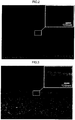
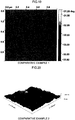
- each reverse osmosis membrane of EXAMPLES 1 and 2 and COMPARATIVE EXAMPLES 1 and 2 were observed using a scanning electron microscope (SEM).
- a surface image and cross-sectional image of the reverse osmosis membrane of EXAMPLE 1 by SEM are shown in FIGS. 2 and 3
- a surface image and cross-sectional image of the reverse osmosis membrane of EXAMPLE 2 by SEM are shown in FIGS. 4 and 5
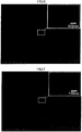
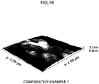
- a surface image and cross-sectional image of the reverse osmosis membrane of COMPARATIVE EXAMPLE 1 by SEM are shown in FIGS. 6 and 7
- a surface image and cross-sectional image of the reverse osmosis membrane of COMPARATIVE EXAMPLE 2 by SEM are shown in FIGS. 8 and 9 .
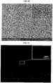
- FIGS. 10 and 11 an image of the surface of the porous support substrate before the carbon membrane is formed (surface of the porous plastic layer), and a cross-sectional image thereof by SEM are shown in FIGS. 10 and 11 , respectively.
- FIGS. 12 and 13 an image of the surface of the porous support substrate provided with the PVP coating (surface of the PVP coating), and a cross-sectional image thereof by SEM are shown in FIGS. 12 and 13 , respectively.
- FIGS. 2 to 8 it is confirmed that, throughout the surface of the porous support substrate, a hole, crack or the like was not formed, but the carbon membrane was uniformly formed. In addition, a hole part that had been found in the surface of the porous support substrate (porous plastic layer) as shown in FIGS. 10 and 11 was not found in the carbon membrane. Furthermore, as shown in FIGS. 12 and 13 , it is confirmed that, when the PVP coating was formed on the surface of the porous support substrate, the hole part in the surface of the porous support substrate (porous plastic layer) was blocked by the PVP coating.
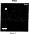
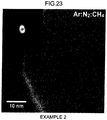
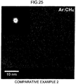
- each carbon membrane of EXAMPLES 1 and 2 and COMPARATIVE EXAMPLES 1 and 2 was observed using a transmission electron microscope (TEM).
- TEM images of EXAMPLES 1 and 2 and COMPARATIVE EXAMPLES 1 and 2 are shown in FIGS. 22 to 25 .
- FIGS. 22 to 25 it becomes clear that each carbon membrane of EXAMPLES 1 and 2 and COMPARATIVE EXAMPLES 1 and 2 had an amorphous-like structure.
- FIGS. 26 and 27 Each carbon membrane of EXAMPLES 1 and 2 and COMPARATIVE EXAMPLES 1 and 2 was analyzed using an electron energy-Loss spectroscopy (EELS). The analysis results from EELS are shown in FIGS. 26 and 27 .
- FIG. 26 is a graph showing EELS intensity against the energy loss in each carbon membrane of EXAMPLES 1 and 2 and COMPARATIVE EXAMPLES 1 and 2
- FIG. 27 is a graph showing the proportion of sp 3 carbon in each carbon membrane of EXAMPLES 1 and 2 and COMPARATIVE EXAMPLES 1 and 2.
- FIG. 26 is a graph showing EELS intensity against the energy loss in each carbon membrane of EXAMPLES 1 and 2 and COMPARATIVE EXAMPLES 1 and 2
- FIG. 27 is a graph showing the proportion of sp 3 carbon in each carbon membrane of EXAMPLES 1 and 2 and COMPARATIVE EXAMPLES 1 and 2.
- FIG. 26 is a graph showing EELS intensity against the energy loss in
- FIGS. 28 C1s
- N1s 29
- O1s O1s
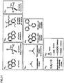
- FIG. 31 is an illustration showing model chemical structures corresponding to the respective regions in C1s, N1s, and O1s for the XPS spectra.
- N 2 as the process gas during membrane formation allowed the nitrogen to be taken in the carbon membrane, so that the amount of nitrogen in the carbon membrane increased.
- oxygen atoms in the carbon membrane are derived from atmospheric oxygen, moisture, and the like.
- the contact angle of each carbon membrane of EXAMPLES 1 and 2 and COMPARATIVE EXAMPLES 1 and 2 with respect to water was measured to evaluate the hydrophilicity of each carbon membrane. Furthermore, based on the contact angle, important parameters such as surface energy were determined.
- the contact angle is a contact angle of the carbon membrane mounted on a silicon wafer with respect to water measured by a usual method.
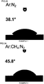
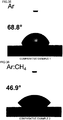
- the results of EXAMPLES 1 and 2 and COMPARATIVE EXAMPLES 1 and 2 are shown in FIGS. 33 to 36 .
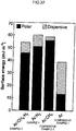
- FIG. 37 shows the corresponding surface energy calculated from the measurement results using water and ethylene glycol.
- the contact angle of EXAMPLE 1 was 38.1°, and the contact angle of EXAMPLE 2 was 45.8°.
- the contact angle of COMPARATIVE EXAMPLE 1 was 68.8°, and the contact angle of COMPARATIVE EXAMPLE 2 was 46.9°.
- the surface energy is expressed as a sum of two components of the polar component and dispersion component.
- the dispersion component is related with a nonpolar group, which contributes to relatively higher hydrophobicity of the carbon film sputtered using only argon gas.
- methane or nitrogen gas in a mixed gas for sputtering not only increased the surface energy as a whole (in particular, its polar component), but also effectively lowered the contact angle with respect to water (made the surface more hydrophilic) .
- the surface energy of each carbon membrane was calculated using the Young's formula which is a general approach for providing the polar component and dispersion component of the surface energy, based on the measurement result of the contact angle and surface tension in terms of two kinds of liquids (water and ethylene glycol).
- infrared absorption spectra were measured using a Fourier transform infrared spectrophotometer (total reflection method). The measurement result is shown in FIG. 38 .
- ATR-FTIR analysis clarifies an important difference in the presence of functional groups in the structure of the carbon membrane (carbon-based nanostructure film), as recognized from the spectra shown in FIG. 38 .
- a mixed gas Ar : CH 4 , Ar : N 2 , and Ar : N 2 : CH 4
- various functional groups were observed, as recognized from the spectra shown in FIG. 38 .
- G band (1350 cm -1 ) and D band (1550 cm -1 ) can be identified, suggesting that each carbon membrane of EXAMPLES 1 and 2 possesses the feature of so-called diamond-like carbon.
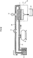
- FIG. 42 is a schematic view of a test device 10 of a cross-flow filtration system.
- the test device 10 includes a filtrating unit 11, a filtrate collecting container 12, a pressure gauge 13, a valve 14, a collecting container 15, a pump 16, an upstream side pipe 17, and a downstream side pipe 18.
- the filtrating unit 11 holds the test samples such as the reverse osmosis membrane 1 such that a solution targeted for filtration (salt water) flows along the surface (carbon membrane) of the test sample (e.g., the reverse osmosis membrane 1), while filtering the solution targeted for filtration on the way of the flow using the test samples.
- the filtrate collecting container 12 is a container 12 for collecting a liquid which has permeated the test sample (permeate solution).
- the solution targeted for filtration (salt water) contained in the collecting container 15 is supplied through the upstream side pipe 17.
- the filtrating unit 11 and the collecting container 15 are connected to each other by the upstream side pipe 17.
- the pump 16 is provided to send to the filtrating unit 11 the solution targeted for filtration.
- the filtrating unit 11 and the collecting container 15 are connected to each other by the downstream side pipe 18, through which the discharged solution targeted for filtration (salt water) from the filtrating unit 11 will be returned to the collecting container 15.
- the pressure gauge 13 and the valve 14 are provided, in which the flow rate of the solution targeted for filtration circulating the downstream side pipe 18 and the like is adjusted by opening/closing the valve 14.
- F is a permeate flux (Lm -2 h -1 )
- L is an amount of permeate water (L)
- S is an effective membrane area of the test sample (m 2 )
- T is a test time (h).
- R is a salt rejection rate (%)
- C1 is an NaCl concentration in the original solution (solution targeted for filtration)
- C2 is an NaCl concentration in the liquid which has permeated the test sample (permeate water).
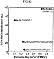
- the evaluation result of water permeation and salt rejection is shown as a graph in FIG. 43 .
- the salt rejection rate by the reverse osmosis membrane of EXAMPLE 1 was 70% or more, from which it is confirmed that the reverse osmosis membrane of EXAMPLE 1 has excellent salt rejection performance.
- the salt rejection by the reverse osmosis membrane of EXAMPLE 2 was up to 96.8%, from which it is confirmed that the reverse osmosis membrane of EXAMPLE 2 has excellent salt rejection performance.
- the salt rejection by each comparative membrane of COMPARATIVE EXAMPLES 1 and 2 was low, from which it is confirmed that the comparative membranes of COMPARATIVE EXAMPLES 1 and 2 have remarkably poor salt rejection performance.
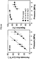
- FIG. 44 is graphs showing a relationship of the pressure with the flux and a relationship of the pressure with the salt rejection rate when solutions targeted for filtration having different concentrations (0.2% by weight sodium chloride aqueous solution, and 3.5% by weight sodium chloride aqueous solution) were filtered through the reverse osmosis membrane of EXAMPLE 2 (the thickness of carbon membrane: approximately 30 nm (30 ⁇ 2 nm)).
- FIG. 44 is graphs showing a relationship of the pressure with the flux and a relationship of the pressure with the salt rejection rate when solutions targeted for filtration having different concentrations (0.2% by weight sodium chloride aqueous solution, and 3.5% by weight sodium chloride aqueous solution) were filtered through the reverse osmosis membrane of EXAMPLE 2 (the thickness of carbon membrane: approximately 30 nm (30 ⁇ 2 nm)).
- Each reverse osmosis membrane of EXAMPLE 2 and EXAMPLES 4 to 6 was immersed in a sodium hypochlorite (NaClO) aqueous solution (200 ppm) for 24 hours. Subsequently, each reverse osmosis membrane was taken out of the aqueous solution and washed with purified water.
- NaClO sodium hypochlorite
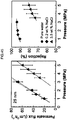
- the reverse osmosis membrane of EXAMPLE 5 was formed under a condition where the supplying concentration of nitrogen gas was set to be approximately 16%. It is confirmed that the reverse osmosis membrane of EXAMPLE 5 considerably inhibited degradation of the carbon membrane (carbon-based nanostructure film) caused by chlorine. As shown in FIG. 46 , even after the membrane was exposed to chlorine in the NaClO exposure treatment, the salt rejection rate for 0.2% by mass sodium chloride aqueous solution was 86%, and the salt rejection rate for 3.5% by mass sodium chloride aqueous solution was 67%. As shown in FIG. 46 , it is confirmed that when the supplying concentration of nitrogen gas was approximately 16% or less, the salt rejection ability of the reverse osmosis membrane (carbon membrane) was maintained.
- Molecular models of three kinds of amorphous carbon were set and analyzed to describe the change caused by nitrogen in the nanostructure of amorphous carbon. These models consist of a) amorphous carbon alone, b) amorphous carbon containing 11% nitrogen, and c) amorphous carbon containing 22% nitrogen. Shown in FIG. 47 is each model after molecular relaxation using a molecular dynamic approach taking Tersoff potential and simulated annealing simulation for structural change into consideration.
- voids are shown within the surface. Ratios of the free volume to the total volume were calculated to be 0.46, 0.37, and 0.30, in cases of amorphous carbon alone, amorphous carbon containing 11% nitrogen, and amorphous carbon containing 22% nitrogen, respectively.
- the void spaces within the amorphous carbon structure were not the factor directly correlated with the water permeation capability, because the non-polar nature of pores within the pure carbon structure may affect passage or adsorption of charge particles, and thus prevent passage of water molecules. This would be understood, because a pure carbon membrane exhibits lower permeate flux in comparison with non-polar organic molecules permeation in the experiments here and in other prior arts.
- the phenomenon illustrated by the simulation may correlate with the experimental structure analysis and water permeation capability. More detailed simulation taking hydrogen and oxygen into consideration can provide more accurate analysis result. We are now conducting more detailed analysis of salt rejection phenomenon from water.
Landscapes
- Chemical & Material Sciences (AREA)
- Chemical Kinetics & Catalysis (AREA)
- Engineering & Computer Science (AREA)
- Water Supply & Treatment (AREA)
- Inorganic Chemistry (AREA)
- Nanotechnology (AREA)
- Manufacturing & Machinery (AREA)
- Separation Using Semi-Permeable Membranes (AREA)
Applications Claiming Priority (4)
| Application Number | Priority Date | Filing Date | Title |
|---|---|---|---|
| JP2015148605 | 2015-07-28 | ||
| JP2015196457 | 2015-10-02 | ||
| JP2016047293A JP6682077B2 (ja) | 2015-07-28 | 2016-03-10 | 逆浸透膜の製造方法 |
| PCT/JP2016/072161 WO2017018482A1 (ja) | 2015-07-28 | 2016-07-28 | 逆浸透膜の製造方法 |
Publications (3)
| Publication Number | Publication Date |
|---|---|
| EP3329985A1 true EP3329985A1 (de) | 2018-06-06 |
| EP3329985A4 EP3329985A4 (de) | 2019-04-10 |
| EP3329985B1 EP3329985B1 (de) | 2022-03-09 |
Family
ID=57884518
Family Applications (1)
| Application Number | Title | Priority Date | Filing Date |
|---|---|---|---|
| EP16830587.8A Not-in-force EP3329985B1 (de) | 2015-07-28 | 2016-07-28 | Verfahren zur herstellung einer umkehrosmose-membran |
Country Status (2)
| Country | Link |
|---|---|
| EP (1) | EP3329985B1 (de) |
| WO (1) | WO2017018482A1 (de) |
Cited By (1)
| Publication number | Priority date | Publication date | Assignee | Title |
|---|---|---|---|---|
| EP3744421A4 (de) * | 2018-01-24 | 2021-10-27 | Kitagawa Industries Co., Ltd. | Umkehrosmosemembran und verfahren zur herstellung einer umkehrosmosemembran |
Family Cites Families (5)
| Publication number | Priority date | Publication date | Assignee | Title |
|---|---|---|---|---|
| US6388366B1 (en) * | 1995-05-08 | 2002-05-14 | Wayne State University | Carbon nitride cold cathode |
| JP5363121B2 (ja) * | 2006-12-28 | 2013-12-11 | 株式会社ミクニ | 水素透過膜、及びその製造方法 |
| JP2011159338A (ja) * | 2010-01-29 | 2011-08-18 | Hitachi Ltd | 磁気ヘッド浮上性評価用ディスク及びその製造方法 |
| JP5527662B2 (ja) * | 2010-08-11 | 2014-06-18 | 独立行政法人物質・材料研究機構 | ナノカーボン膜の製造方法及びナノカーボン膜 |
| WO2015080259A1 (ja) * | 2013-11-29 | 2015-06-04 | 独立行政法人物質・材料研究機構 | 硬質カーボン膜製nf又はro膜、濾過フィルター、2層接合型濾過フィルター及びそれらの製造方法 |
-
2016
- 2016-07-28 WO PCT/JP2016/072161 patent/WO2017018482A1/ja not_active Ceased
- 2016-07-28 EP EP16830587.8A patent/EP3329985B1/de not_active Not-in-force
Cited By (1)
| Publication number | Priority date | Publication date | Assignee | Title |
|---|---|---|---|---|
| EP3744421A4 (de) * | 2018-01-24 | 2021-10-27 | Kitagawa Industries Co., Ltd. | Umkehrosmosemembran und verfahren zur herstellung einer umkehrosmosemembran |
Also Published As
| Publication number | Publication date |
|---|---|
| EP3329985A4 (de) | 2019-04-10 |
| WO2017018482A1 (ja) | 2017-02-02 |
| EP3329985B1 (de) | 2022-03-09 |
Similar Documents
| Publication | Publication Date | Title |
|---|---|---|
| JP5707596B2 (ja) | 非対称性膜 | |
| EP2962748B1 (de) | Halbdurchlässige verbundmembran und herstellung davon | |
| Ding et al. | Effects of polysulfone (PSf) support layer on the performance of thin-film composite (TFC) membranes | |
| Yan et al. | Enhancing the flux of brackish water TFC RO membrane by improving support surface porosity via a secondary pore-forming method | |
| EP2025390B1 (de) | Gastrennmembran auf einem mikroporösen polyolefinträger | |
| Zhou et al. | Controlled TiO2 growth on reverse osmosis and nanofiltration membranes by atomic layer deposition: mechanisms and potential applications | |
| Liu et al. | The preparation of antifouling ultrafiltration membrane by surface grafting zwitterionic polymer onto poly (arylene ether sulfone) containing hydroxyl groups membrane | |
| Buonomenna et al. | New PVDF membranes: The effect of plasma surface modification on retention in nanofiltration of aqueous solution containing organic compounds | |
| JP6608811B2 (ja) | 耐酸化性及び耐塩素性に優れたポリアミド系水処理分離膜及びその製造方法 | |
| EP2332638A1 (de) | Poröse membran, verfahren zur herstellung der porösen membran, verfahren zur herstellung einer klaren flüssigkeit und modul mit einer porösen membran | |
| EP3578249A1 (de) | Semipermeable verbundmembran und verfahren zur herstellung einer semipermeablen verbundmembran | |
| Li et al. | Exploring the dependence of bulk properties on surface chemistries and microstructures of commercially composite RO membranes by novel characterization approaches | |
| EP3395434B1 (de) | Halbdurchlässige verbundmembran | |
| EP3162432A1 (de) | Halbdurchlässige verbundmembran | |
| US20110017660A1 (en) | Hollow-fiber ultrafiltration membrane with excellent fouling resistance | |
| Kusworo et al. | Performance evaluation of PES-ZnO nanohybrid using a combination of UV irradiation and cross-linking for wastewater treatment of the rubber industry to clean water | |
| EP3329985B1 (de) | Verfahren zur herstellung einer umkehrosmose-membran | |
| Arahman et al. | Exploring the effect of CNTs and pluronic on characteristics and stability of polyethersulfone (PES) and polyvinylidene fluoride (PVDF) membranes | |
| EP4534187A1 (de) | Semipermeable verbundmembran und verfahren zur herstellung davon | |
| US10751668B2 (en) | Method of forming reverse osmosis membrane | |
| EP4065257A1 (de) | Verfahren zur herstellung von porösen filtermembranen | |
| Luo et al. | Small is better: Impact of polyelectrolyte Mw on layer-by-layer nanofiltration membranes for PFAS removal | |
| EP2763787A1 (de) | Abrasionsbeständige filtrationsmembran und verfahren zu ihrer herstellung | |
| JP5527662B2 (ja) | ナノカーボン膜の製造方法及びナノカーボン膜 | |
| EP3744421A1 (de) | Umkehrosmosemembran und verfahren zur herstellung einer umkehrosmosemembran |
Legal Events
| Date | Code | Title | Description |
|---|---|---|---|
| STAA | Information on the status of an ep patent application or granted ep patent |
Free format text: STATUS: THE INTERNATIONAL PUBLICATION HAS BEEN MADE |
|
| PUAI | Public reference made under article 153(3) epc to a published international application that has entered the european phase |
Free format text: ORIGINAL CODE: 0009012 |
|
| STAA | Information on the status of an ep patent application or granted ep patent |
Free format text: STATUS: REQUEST FOR EXAMINATION WAS MADE |
|
| 17P | Request for examination filed |
Effective date: 20180125 |
|
| AK | Designated contracting states |
Kind code of ref document: A1 Designated state(s): AL AT BE BG CH CY CZ DE DK EE ES FI FR GB GR HR HU IE IS IT LI LT LU LV MC MK MT NL NO PL PT RO RS SE SI SK SM TR |
|
| AX | Request for extension of the european patent |
Extension state: BA ME |
|
| DAV | Request for validation of the european patent (deleted) | ||
| DAX | Request for extension of the european patent (deleted) | ||
| A4 | Supplementary search report drawn up and despatched |
Effective date: 20190307 |
|
| RIC1 | Information provided on ipc code assigned before grant |
Ipc: B01D 61/02 20060101ALI20190301BHEP Ipc: B01D 69/10 20060101ALI20190301BHEP Ipc: B01D 69/12 20060101ALI20190301BHEP Ipc: B01D 71/02 20060101AFI20190301BHEP |
|
| STAA | Information on the status of an ep patent application or granted ep patent |
Free format text: STATUS: EXAMINATION IS IN PROGRESS |
|
| 17Q | First examination report despatched |
Effective date: 20200512 |
|
| GRAP | Despatch of communication of intention to grant a patent |
Free format text: ORIGINAL CODE: EPIDOSNIGR1 |
|
| STAA | Information on the status of an ep patent application or granted ep patent |
Free format text: STATUS: GRANT OF PATENT IS INTENDED |
|
| INTG | Intention to grant announced |
Effective date: 20211008 |
|
| GRAS | Grant fee paid |
Free format text: ORIGINAL CODE: EPIDOSNIGR3 |
|
| GRAA | (expected) grant |
Free format text: ORIGINAL CODE: 0009210 |
|
| STAA | Information on the status of an ep patent application or granted ep patent |
Free format text: STATUS: THE PATENT HAS BEEN GRANTED |
|
| AK | Designated contracting states |
Kind code of ref document: B1 Designated state(s): AL AT BE BG CH CY CZ DE DK EE ES FI FR GB GR HR HU IE IS IT LI LT LU LV MC MK MT NL NO PL PT RO RS SE SI SK SM TR |
|
| REG | Reference to a national code |
Ref country code: GB Ref legal event code: FG4D |
|
| REG | Reference to a national code |
Ref country code: CH Ref legal event code: EP Ref country code: AT Ref legal event code: REF Ref document number: 1473663 Country of ref document: AT Kind code of ref document: T Effective date: 20220315 |
|
| REG | Reference to a national code |
Ref country code: IE Ref legal event code: FG4D |
|
| REG | Reference to a national code |
Ref country code: DE Ref legal event code: R096 Ref document number: 602016069905 Country of ref document: DE |
|
| REG | Reference to a national code |
Ref country code: LT Ref legal event code: MG9D |
|
| REG | Reference to a national code |
Ref country code: NL Ref legal event code: MP Effective date: 20220309 |
|
| PG25 | Lapsed in a contracting state [announced via postgrant information from national office to epo] |
Ref country code: SE Free format text: LAPSE BECAUSE OF FAILURE TO SUBMIT A TRANSLATION OF THE DESCRIPTION OR TO PAY THE FEE WITHIN THE PRESCRIBED TIME-LIMIT Effective date: 20220309 Ref country code: RS Free format text: LAPSE BECAUSE OF FAILURE TO SUBMIT A TRANSLATION OF THE DESCRIPTION OR TO PAY THE FEE WITHIN THE PRESCRIBED TIME-LIMIT Effective date: 20220309 Ref country code: NO Free format text: LAPSE BECAUSE OF FAILURE TO SUBMIT A TRANSLATION OF THE DESCRIPTION OR TO PAY THE FEE WITHIN THE PRESCRIBED TIME-LIMIT Effective date: 20220609 Ref country code: LT Free format text: LAPSE BECAUSE OF FAILURE TO SUBMIT A TRANSLATION OF THE DESCRIPTION OR TO PAY THE FEE WITHIN THE PRESCRIBED TIME-LIMIT Effective date: 20220309 Ref country code: HR Free format text: LAPSE BECAUSE OF FAILURE TO SUBMIT A TRANSLATION OF THE DESCRIPTION OR TO PAY THE FEE WITHIN THE PRESCRIBED TIME-LIMIT Effective date: 20220309 Ref country code: BG Free format text: LAPSE BECAUSE OF FAILURE TO SUBMIT A TRANSLATION OF THE DESCRIPTION OR TO PAY THE FEE WITHIN THE PRESCRIBED TIME-LIMIT Effective date: 20220609 |
|
| REG | Reference to a national code |
Ref country code: AT Ref legal event code: MK05 Ref document number: 1473663 Country of ref document: AT Kind code of ref document: T Effective date: 20220309 |
|
| PG25 | Lapsed in a contracting state [announced via postgrant information from national office to epo] |
Ref country code: LV Free format text: LAPSE BECAUSE OF FAILURE TO SUBMIT A TRANSLATION OF THE DESCRIPTION OR TO PAY THE FEE WITHIN THE PRESCRIBED TIME-LIMIT Effective date: 20220309 Ref country code: GR Free format text: LAPSE BECAUSE OF FAILURE TO SUBMIT A TRANSLATION OF THE DESCRIPTION OR TO PAY THE FEE WITHIN THE PRESCRIBED TIME-LIMIT Effective date: 20220610 Ref country code: FI Free format text: LAPSE BECAUSE OF FAILURE TO SUBMIT A TRANSLATION OF THE DESCRIPTION OR TO PAY THE FEE WITHIN THE PRESCRIBED TIME-LIMIT Effective date: 20220309 |
|
| PG25 | Lapsed in a contracting state [announced via postgrant information from national office to epo] |
Ref country code: NL Free format text: LAPSE BECAUSE OF FAILURE TO SUBMIT A TRANSLATION OF THE DESCRIPTION OR TO PAY THE FEE WITHIN THE PRESCRIBED TIME-LIMIT Effective date: 20220309 |
|
| PG25 | Lapsed in a contracting state [announced via postgrant information from national office to epo] |
Ref country code: SM Free format text: LAPSE BECAUSE OF FAILURE TO SUBMIT A TRANSLATION OF THE DESCRIPTION OR TO PAY THE FEE WITHIN THE PRESCRIBED TIME-LIMIT Effective date: 20220309 Ref country code: SK Free format text: LAPSE BECAUSE OF FAILURE TO SUBMIT A TRANSLATION OF THE DESCRIPTION OR TO PAY THE FEE WITHIN THE PRESCRIBED TIME-LIMIT Effective date: 20220309 Ref country code: RO Free format text: LAPSE BECAUSE OF FAILURE TO SUBMIT A TRANSLATION OF THE DESCRIPTION OR TO PAY THE FEE WITHIN THE PRESCRIBED TIME-LIMIT Effective date: 20220309 Ref country code: PT Free format text: LAPSE BECAUSE OF FAILURE TO SUBMIT A TRANSLATION OF THE DESCRIPTION OR TO PAY THE FEE WITHIN THE PRESCRIBED TIME-LIMIT Effective date: 20220711 Ref country code: ES Free format text: LAPSE BECAUSE OF FAILURE TO SUBMIT A TRANSLATION OF THE DESCRIPTION OR TO PAY THE FEE WITHIN THE PRESCRIBED TIME-LIMIT Effective date: 20220309 Ref country code: EE Free format text: LAPSE BECAUSE OF FAILURE TO SUBMIT A TRANSLATION OF THE DESCRIPTION OR TO PAY THE FEE WITHIN THE PRESCRIBED TIME-LIMIT Effective date: 20220309 Ref country code: CZ Free format text: LAPSE BECAUSE OF FAILURE TO SUBMIT A TRANSLATION OF THE DESCRIPTION OR TO PAY THE FEE WITHIN THE PRESCRIBED TIME-LIMIT Effective date: 20220309 Ref country code: AT Free format text: LAPSE BECAUSE OF FAILURE TO SUBMIT A TRANSLATION OF THE DESCRIPTION OR TO PAY THE FEE WITHIN THE PRESCRIBED TIME-LIMIT Effective date: 20220309 |
|
| PG25 | Lapsed in a contracting state [announced via postgrant information from national office to epo] |
Ref country code: PL Free format text: LAPSE BECAUSE OF FAILURE TO SUBMIT A TRANSLATION OF THE DESCRIPTION OR TO PAY THE FEE WITHIN THE PRESCRIBED TIME-LIMIT Effective date: 20220309 Ref country code: IS Free format text: LAPSE BECAUSE OF FAILURE TO SUBMIT A TRANSLATION OF THE DESCRIPTION OR TO PAY THE FEE WITHIN THE PRESCRIBED TIME-LIMIT Effective date: 20220709 Ref country code: AL Free format text: LAPSE BECAUSE OF FAILURE TO SUBMIT A TRANSLATION OF THE DESCRIPTION OR TO PAY THE FEE WITHIN THE PRESCRIBED TIME-LIMIT Effective date: 20220309 |
|
| REG | Reference to a national code |
Ref country code: DE Ref legal event code: R097 Ref document number: 602016069905 Country of ref document: DE |
|
| PLBE | No opposition filed within time limit |
Free format text: ORIGINAL CODE: 0009261 |
|
| STAA | Information on the status of an ep patent application or granted ep patent |
Free format text: STATUS: NO OPPOSITION FILED WITHIN TIME LIMIT |
|
| PG25 | Lapsed in a contracting state [announced via postgrant information from national office to epo] |
Ref country code: DK Free format text: LAPSE BECAUSE OF FAILURE TO SUBMIT A TRANSLATION OF THE DESCRIPTION OR TO PAY THE FEE WITHIN THE PRESCRIBED TIME-LIMIT Effective date: 20220309 |
|
| 26N | No opposition filed |
Effective date: 20221212 |
|
| PG25 | Lapsed in a contracting state [announced via postgrant information from national office to epo] |
Ref country code: SI Free format text: LAPSE BECAUSE OF FAILURE TO SUBMIT A TRANSLATION OF THE DESCRIPTION OR TO PAY THE FEE WITHIN THE PRESCRIBED TIME-LIMIT Effective date: 20220309 Ref country code: MC Free format text: LAPSE BECAUSE OF FAILURE TO SUBMIT A TRANSLATION OF THE DESCRIPTION OR TO PAY THE FEE WITHIN THE PRESCRIBED TIME-LIMIT Effective date: 20220309 |
|
| REG | Reference to a national code |
Ref country code: CH Ref legal event code: PL |
|
| GBPC | Gb: european patent ceased through non-payment of renewal fee |
Effective date: 20220728 |
|
| REG | Reference to a national code |
Ref country code: BE Ref legal event code: MM Effective date: 20220731 |
|
| PG25 | Lapsed in a contracting state [announced via postgrant information from national office to epo] |
Ref country code: LU Free format text: LAPSE BECAUSE OF NON-PAYMENT OF DUE FEES Effective date: 20220728 Ref country code: LI Free format text: LAPSE BECAUSE OF NON-PAYMENT OF DUE FEES Effective date: 20220731 Ref country code: CH Free format text: LAPSE BECAUSE OF NON-PAYMENT OF DUE FEES Effective date: 20220731 |
|
| PG25 | Lapsed in a contracting state [announced via postgrant information from national office to epo] |
Ref country code: GB Free format text: LAPSE BECAUSE OF NON-PAYMENT OF DUE FEES Effective date: 20220728 Ref country code: BE Free format text: LAPSE BECAUSE OF NON-PAYMENT OF DUE FEES Effective date: 20220731 |
|
| PG25 | Lapsed in a contracting state [announced via postgrant information from national office to epo] |
Ref country code: IT Free format text: LAPSE BECAUSE OF FAILURE TO SUBMIT A TRANSLATION OF THE DESCRIPTION OR TO PAY THE FEE WITHIN THE PRESCRIBED TIME-LIMIT Effective date: 20220309 Ref country code: IE Free format text: LAPSE BECAUSE OF NON-PAYMENT OF DUE FEES Effective date: 20220728 |
|
| PG25 | Lapsed in a contracting state [announced via postgrant information from national office to epo] |
Ref country code: HU Free format text: LAPSE BECAUSE OF FAILURE TO SUBMIT A TRANSLATION OF THE DESCRIPTION OR TO PAY THE FEE WITHIN THE PRESCRIBED TIME-LIMIT; INVALID AB INITIO Effective date: 20160728 |
|
| PG25 | Lapsed in a contracting state [announced via postgrant information from national office to epo] |
Ref country code: MK Free format text: LAPSE BECAUSE OF FAILURE TO SUBMIT A TRANSLATION OF THE DESCRIPTION OR TO PAY THE FEE WITHIN THE PRESCRIBED TIME-LIMIT Effective date: 20220309 Ref country code: CY Free format text: LAPSE BECAUSE OF FAILURE TO SUBMIT A TRANSLATION OF THE DESCRIPTION OR TO PAY THE FEE WITHIN THE PRESCRIBED TIME-LIMIT Effective date: 20220309 |
|
| PG25 | Lapsed in a contracting state [announced via postgrant information from national office to epo] |
Ref country code: MT Free format text: LAPSE BECAUSE OF FAILURE TO SUBMIT A TRANSLATION OF THE DESCRIPTION OR TO PAY THE FEE WITHIN THE PRESCRIBED TIME-LIMIT Effective date: 20220309 |
|
| PGFP | Annual fee paid to national office [announced via postgrant information from national office to epo] |
Ref country code: DE Payment date: 20240730 Year of fee payment: 9 |
|
| PGFP | Annual fee paid to national office [announced via postgrant information from national office to epo] |
Ref country code: FR Payment date: 20240730 Year of fee payment: 9 |
|
| PG25 | Lapsed in a contracting state [announced via postgrant information from national office to epo] |
Ref country code: TR Free format text: LAPSE BECAUSE OF FAILURE TO SUBMIT A TRANSLATION OF THE DESCRIPTION OR TO PAY THE FEE WITHIN THE PRESCRIBED TIME-LIMIT Effective date: 20220309 |
|
| REG | Reference to a national code |
Ref country code: DE Ref legal event code: R119 Ref document number: 602016069905 Country of ref document: DE |
|
| PG25 | Lapsed in a contracting state [announced via postgrant information from national office to epo] |
Ref country code: DE Free format text: LAPSE BECAUSE OF NON-PAYMENT OF DUE FEES Effective date: 20260203 |
|
| PG25 | Lapsed in a contracting state [announced via postgrant information from national office to epo] |
Ref country code: FR Free format text: LAPSE BECAUSE OF NON-PAYMENT OF DUE FEES Effective date: 20250731 |