EP3329884B1 - Dispositif implantable pour le traitement du glaucome - Google Patents
Dispositif implantable pour le traitement du glaucome Download PDFInfo
- Publication number
- EP3329884B1 EP3329884B1 EP18152701.1A EP18152701A EP3329884B1 EP 3329884 B1 EP3329884 B1 EP 3329884B1 EP 18152701 A EP18152701 A EP 18152701A EP 3329884 B1 EP3329884 B1 EP 3329884B1
- Authority
- EP
- European Patent Office
- Prior art keywords
- tube
- tabs
- aqueous humor
- passage
- tissue
- Prior art date
- Legal status (The legal status is an assumption and is not a legal conclusion. Google has not performed a legal analysis and makes no representation as to the accuracy of the status listed.)
- Active
Links
- 208000010412 Glaucoma Diseases 0.000 title description 19
- 210000001742 aqueous humor Anatomy 0.000 claims description 94
- 210000001519 tissue Anatomy 0.000 claims description 50
- 239000003814 drug Substances 0.000 claims description 46
- 210000002159 anterior chamber Anatomy 0.000 claims description 41
- 239000000463 material Substances 0.000 claims description 39
- 229920000642 polymer Polymers 0.000 claims description 37
- 229940124597 therapeutic agent Drugs 0.000 claims description 33
- 238000007789 sealing Methods 0.000 claims description 11
- 229920002635 polyurethane Polymers 0.000 claims description 6
- 239000004814 polyurethane Substances 0.000 claims description 6
- 229920002379 silicone rubber Polymers 0.000 claims description 4
- 239000004945 silicone rubber Substances 0.000 claims description 4
- 239000004952 Polyamide Substances 0.000 claims description 3
- 229920002313 fluoropolymer Polymers 0.000 claims description 3
- 239000004811 fluoropolymer Substances 0.000 claims description 3
- 229920002647 polyamide Polymers 0.000 claims description 3
- 229920000098 polyolefin Polymers 0.000 claims description 3
- 230000004044 response Effects 0.000 claims description 3
- 239000000017 hydrogel Substances 0.000 claims description 2
- 229920000058 polyacrylate Polymers 0.000 claims description 2
- 239000002861 polymer material Substances 0.000 claims description 2
- 239000006261 foam material Substances 0.000 claims 1
- 210000001508 eye Anatomy 0.000 description 47
- 210000003786 sclera Anatomy 0.000 description 35
- UCTWMZQNUQWSLP-VIFPVBQESA-N (R)-adrenaline Chemical compound CNC[C@H](O)C1=CC=C(O)C(O)=C1 UCTWMZQNUQWSLP-VIFPVBQESA-N 0.000 description 21
- 210000000795 conjunctiva Anatomy 0.000 description 17
- 239000012528 membrane Substances 0.000 description 17
- 239000012530 fluid Substances 0.000 description 15
- 238000000034 method Methods 0.000 description 15
- 208000002352 blister Diseases 0.000 description 14
- 229920001400 block copolymer Polymers 0.000 description 13
- 238000013461 design Methods 0.000 description 13
- -1 styrene-ethylene-propylene-butadiene Chemical class 0.000 description 13
- PPBRXRYQALVLMV-UHFFFAOYSA-N Styrene Chemical compound C=CC1=CC=CC=C1 PPBRXRYQALVLMV-UHFFFAOYSA-N 0.000 description 12
- 229940079593 drug Drugs 0.000 description 12
- 239000003795 chemical substances by application Substances 0.000 description 11
- 235000019589 hardness Nutrition 0.000 description 11
- 229920001577 copolymer Polymers 0.000 description 10
- 239000000203 mixture Substances 0.000 description 10
- 210000001585 trabecular meshwork Anatomy 0.000 description 9
- 210000004027 cell Anatomy 0.000 description 8
- 206010041899 Stab wound Diseases 0.000 description 7
- 239000010410 layer Substances 0.000 description 7
- 230000005012 migration Effects 0.000 description 7
- 238000013508 migration Methods 0.000 description 7
- 206010016654 Fibrosis Diseases 0.000 description 6
- NWIBSHFKIJFRCO-WUDYKRTCSA-N Mytomycin Chemical compound C1N2C(C(C(C)=C(N)C3=O)=O)=C3[C@@H](COC(N)=O)[C@@]2(OC)[C@@H]2[C@H]1N2 NWIBSHFKIJFRCO-WUDYKRTCSA-N 0.000 description 6
- 239000004793 Polystyrene Substances 0.000 description 6
- 230000004761 fibrosis Effects 0.000 description 6
- 230000006870 function Effects 0.000 description 6
- 230000002401 inhibitory effect Effects 0.000 description 6
- 229920002223 polystyrene Polymers 0.000 description 6
- 108010035532 Collagen Proteins 0.000 description 5
- 102000008186 Collagen Human genes 0.000 description 5
- 229920002367 Polyisobutene Polymers 0.000 description 5
- 230000001028 anti-proliverative effect Effects 0.000 description 5
- 230000015572 biosynthetic process Effects 0.000 description 5
- 229920001436 collagen Polymers 0.000 description 5
- 210000004087 cornea Anatomy 0.000 description 5
- 238000005520 cutting process Methods 0.000 description 5
- 230000004406 elevated intraocular pressure Effects 0.000 description 5
- 230000003628 erosive effect Effects 0.000 description 5
- 238000003780 insertion Methods 0.000 description 5
- 230000037431 insertion Effects 0.000 description 5
- 238000002483 medication Methods 0.000 description 5
- 239000002904 solvent Substances 0.000 description 5
- 238000001356 surgical procedure Methods 0.000 description 5
- 229920001169 thermoplastic Polymers 0.000 description 5
- 239000004416 thermosoftening plastic Substances 0.000 description 5
- 201000004569 Blindness Diseases 0.000 description 4
- 102000016805 Guanine Nucleotide Dissociation Inhibitors Human genes 0.000 description 4
- 108010092964 Guanine Nucleotide Dissociation Inhibitors Proteins 0.000 description 4
- MWUXSHHQAYIFBG-UHFFFAOYSA-N Nitric oxide Chemical compound O=[N] MWUXSHHQAYIFBG-UHFFFAOYSA-N 0.000 description 4
- 206010030348 Open-Angle Glaucoma Diseases 0.000 description 4
- 238000000576 coating method Methods 0.000 description 4
- 238000004891 communication Methods 0.000 description 4
- 238000000165 glow discharge ionisation Methods 0.000 description 4
- 230000001771 impaired effect Effects 0.000 description 4
- 239000007943 implant Substances 0.000 description 4
- 239000003112 inhibitor Substances 0.000 description 4
- 210000001328 optic nerve Anatomy 0.000 description 4
- 201000002862 Angle-Closure Glaucoma Diseases 0.000 description 3
- 239000004721 Polyphenylene oxide Substances 0.000 description 3
- 239000004743 Polypropylene Substances 0.000 description 3
- 239000005557 antagonist Substances 0.000 description 3
- 230000001413 cellular effect Effects 0.000 description 3
- 239000011248 coating agent Substances 0.000 description 3
- 150000001875 compounds Chemical class 0.000 description 3
- 230000000694 effects Effects 0.000 description 3
- 239000005038 ethylene vinyl acetate Substances 0.000 description 3
- 239000000835 fiber Substances 0.000 description 3
- 238000001914 filtration Methods 0.000 description 3
- 238000004519 manufacturing process Methods 0.000 description 3
- 229960004857 mitomycin Drugs 0.000 description 3
- 229920001200 poly(ethylene-vinyl acetate) Polymers 0.000 description 3
- 229920001155 polypropylene Polymers 0.000 description 3
- 201000006366 primary open angle glaucoma Diseases 0.000 description 3
- 238000012545 processing Methods 0.000 description 3
- YUWPMEXLKGOSBF-GACAOOTBSA-N Anecortave acetate Chemical compound O=C1CC[C@]2(C)C3=CC[C@]4(C)[C@](C(=O)COC(=O)C)(O)CC[C@H]4[C@@H]3CCC2=C1 YUWPMEXLKGOSBF-GACAOOTBSA-N 0.000 description 2
- 239000004971 Cross linker Substances 0.000 description 2
- 208000003164 Diplopia Diseases 0.000 description 2
- AOJJSUZBOXZQNB-TZSSRYMLSA-N Doxorubicin Chemical compound O([C@H]1C[C@@](O)(CC=2C(O)=C3C(=O)C=4C=CC=C(C=4C(=O)C3=C(O)C=21)OC)C(=O)CO)[C@H]1C[C@H](N)[C@H](O)[C@H](C)O1 AOJJSUZBOXZQNB-TZSSRYMLSA-N 0.000 description 2
- 102000004190 Enzymes Human genes 0.000 description 2
- 108090000790 Enzymes Proteins 0.000 description 2
- GHASVSINZRGABV-UHFFFAOYSA-N Fluorouracil Chemical compound FC1=CNC(=O)NC1=O GHASVSINZRGABV-UHFFFAOYSA-N 0.000 description 2
- HTTJABKRGRZYRN-UHFFFAOYSA-N Heparin Chemical compound OC1C(NC(=O)C)C(O)OC(COS(O)(=O)=O)C1OC1C(OS(O)(=O)=O)C(O)C(OC2C(C(OS(O)(=O)=O)C(OC3C(C(O)C(O)C(O3)C(O)=O)OS(O)(=O)=O)C(CO)O2)NS(O)(=O)=O)C(C(O)=O)O1 HTTJABKRGRZYRN-UHFFFAOYSA-N 0.000 description 2
- 239000004705 High-molecular-weight polyethylene Substances 0.000 description 2
- 241000282412 Homo Species 0.000 description 2
- 229930012538 Paclitaxel Natural products 0.000 description 2
- 239000004698 Polyethylene Substances 0.000 description 2
- NKANXQFJJICGDU-QPLCGJKRSA-N Tamoxifen Chemical compound C=1C=CC=CC=1C(/CC)=C(C=1C=CC(OCCN(C)C)=CC=1)/C1=CC=CC=C1 NKANXQFJJICGDU-QPLCGJKRSA-N 0.000 description 2
- 208000007536 Thrombosis Diseases 0.000 description 2
- 230000002159 abnormal effect Effects 0.000 description 2
- 239000000853 adhesive Substances 0.000 description 2
- 230000001070 adhesive effect Effects 0.000 description 2
- 229960001232 anecortave Drugs 0.000 description 2
- 239000011230 binding agent Substances 0.000 description 2
- 230000032823 cell division Effects 0.000 description 2
- 230000012292 cell migration Effects 0.000 description 2
- 230000004663 cell proliferation Effects 0.000 description 2
- 210000004240 ciliary body Anatomy 0.000 description 2
- 230000001886 ciliary effect Effects 0.000 description 2
- 230000015271 coagulation Effects 0.000 description 2
- 238000005345 coagulation Methods 0.000 description 2
- 210000002808 connective tissue Anatomy 0.000 description 2
- 239000000470 constituent Substances 0.000 description 2
- 239000003246 corticosteroid Substances 0.000 description 2
- 239000000824 cytostatic agent Substances 0.000 description 2
- 230000006378 damage Effects 0.000 description 2
- 230000003247 decreasing effect Effects 0.000 description 2
- 238000009792 diffusion process Methods 0.000 description 2
- KPUWHANPEXNPJT-UHFFFAOYSA-N disiloxane Chemical class [SiH3]O[SiH3] KPUWHANPEXNPJT-UHFFFAOYSA-N 0.000 description 2
- 238000002224 dissection Methods 0.000 description 2
- 238000005538 encapsulation Methods 0.000 description 2
- 229940088598 enzyme Drugs 0.000 description 2
- 229960002949 fluorouracil Drugs 0.000 description 2
- 125000000524 functional group Chemical group 0.000 description 2
- 150000004676 glycans Chemical class 0.000 description 2
- 239000003102 growth factor Substances 0.000 description 2
- 229920000669 heparin Polymers 0.000 description 2
- 229960002897 heparin Drugs 0.000 description 2
- 102000006495 integrins Human genes 0.000 description 2
- 108010044426 integrins Proteins 0.000 description 2
- 230000004410 intraocular pressure Effects 0.000 description 2
- 238000003475 lamination Methods 0.000 description 2
- 230000033001 locomotion Effects 0.000 description 2
- 229910052751 metal Inorganic materials 0.000 description 2
- 239000002184 metal Substances 0.000 description 2
- 238000000465 moulding Methods 0.000 description 2
- 229960001592 paclitaxel Drugs 0.000 description 2
- 230000037361 pathway Effects 0.000 description 2
- 229920003023 plastic Polymers 0.000 description 2
- 239000004033 plastic Substances 0.000 description 2
- 229920001281 polyalkylene Polymers 0.000 description 2
- 229920000570 polyether Polymers 0.000 description 2
- 229920000573 polyethylene Polymers 0.000 description 2
- 229920006380 polyphenylene oxide Polymers 0.000 description 2
- 229920001282 polysaccharide Polymers 0.000 description 2
- 239000005017 polysaccharide Substances 0.000 description 2
- 229920001343 polytetrafluoroethylene Polymers 0.000 description 2
- 239000004810 polytetrafluoroethylene Substances 0.000 description 2
- 229920000036 polyvinylpyrrolidone Polymers 0.000 description 2
- 235000013855 polyvinylpyrrolidone Nutrition 0.000 description 2
- 239000001267 polyvinylpyrrolidone Substances 0.000 description 2
- 239000003755 preservative agent Substances 0.000 description 2
- 230000000750 progressive effect Effects 0.000 description 2
- 230000001179 pupillary effect Effects 0.000 description 2
- 230000010076 replication Effects 0.000 description 2
- 229910001220 stainless steel Inorganic materials 0.000 description 2
- 239000010935 stainless steel Substances 0.000 description 2
- RCINICONZNJXQF-MZXODVADSA-N taxol Chemical compound O([C@@H]1[C@@]2(C[C@@H](C(C)=C(C2(C)C)[C@H](C([C@]2(C)[C@@H](O)C[C@H]3OC[C@]3([C@H]21)OC(C)=O)=O)OC(=O)C)OC(=O)[C@H](O)[C@@H](NC(=O)C=1C=CC=CC=1)C=1C=CC=CC=1)O)C(=O)C1=CC=CC=C1 RCINICONZNJXQF-MZXODVADSA-N 0.000 description 2
- 230000001225 therapeutic effect Effects 0.000 description 2
- 229920002554 vinyl polymer Polymers 0.000 description 2
- 230000004393 visual impairment Effects 0.000 description 2
- KIUKXJAPPMFGSW-DNGZLQJQSA-N (2S,3S,4S,5R,6R)-6-[(2S,3R,4R,5S,6R)-3-Acetamido-2-[(2S,3S,4R,5R,6R)-6-[(2R,3R,4R,5S,6R)-3-acetamido-2,5-dihydroxy-6-(hydroxymethyl)oxan-4-yl]oxy-2-carboxy-4,5-dihydroxyoxan-3-yl]oxy-5-hydroxy-6-(hydroxymethyl)oxan-4-yl]oxy-3,4,5-trihydroxyoxane-2-carboxylic acid Chemical compound CC(=O)N[C@H]1[C@H](O)O[C@H](CO)[C@@H](O)[C@@H]1O[C@H]1[C@H](O)[C@@H](O)[C@H](O[C@H]2[C@@H]([C@@H](O[C@H]3[C@@H]([C@@H](O)[C@H](O)[C@H](O3)C(O)=O)O)[C@H](O)[C@@H](CO)O2)NC(C)=O)[C@@H](C(O)=O)O1 KIUKXJAPPMFGSW-DNGZLQJQSA-N 0.000 description 1
- 229930182837 (R)-adrenaline Natural products 0.000 description 1
- 101710175516 14 kDa zinc-binding protein Proteins 0.000 description 1
- CQOQDQWUFQDJMK-SSTWWWIQSA-N 2-methoxy-17beta-estradiol Chemical compound C([C@@H]12)C[C@]3(C)[C@@H](O)CC[C@H]3[C@@H]1CCC1=C2C=C(OC)C(O)=C1 CQOQDQWUFQDJMK-SSTWWWIQSA-N 0.000 description 1
- WLCZTRVUXYALDD-IBGZPJMESA-N 7-[[(2s)-2,6-bis(2-methoxyethoxycarbonylamino)hexanoyl]amino]heptoxy-methylphosphinic acid Chemical compound COCCOC(=O)NCCCC[C@H](NC(=O)OCCOC)C(=O)NCCCCCCCOP(C)(O)=O WLCZTRVUXYALDD-IBGZPJMESA-N 0.000 description 1
- 102400000068 Angiostatin Human genes 0.000 description 1
- 108010079709 Angiostatins Proteins 0.000 description 1
- 108020000948 Antisense Oligonucleotides Proteins 0.000 description 1
- 208000032467 Aplastic anaemia Diseases 0.000 description 1
- 102100040214 Apolipoprotein(a) Human genes 0.000 description 1
- 108010012927 Apoprotein(a) Proteins 0.000 description 1
- 108091023037 Aptamer Proteins 0.000 description 1
- 241000894006 Bacteria Species 0.000 description 1
- 206010007559 Cardiac failure congestive Diseases 0.000 description 1
- HVXBOLULGPECHP-WAYWQWQTSA-N Combretastatin A4 Chemical compound C1=C(O)C(OC)=CC=C1\C=C/C1=CC(OC)=C(OC)C(OC)=C1 HVXBOLULGPECHP-WAYWQWQTSA-N 0.000 description 1
- 229920001651 Cyanoacrylate Polymers 0.000 description 1
- 102000004127 Cytokines Human genes 0.000 description 1
- 108090000695 Cytokines Proteins 0.000 description 1
- 102000004163 DNA-directed RNA polymerases Human genes 0.000 description 1
- 108090000626 DNA-directed RNA polymerases Proteins 0.000 description 1
- 229920002307 Dextran Polymers 0.000 description 1
- 102000016942 Elastin Human genes 0.000 description 1
- 108010014258 Elastin Proteins 0.000 description 1
- 102400001047 Endostatin Human genes 0.000 description 1
- 108010079505 Endostatins Proteins 0.000 description 1
- 108050009340 Endothelin Proteins 0.000 description 1
- 102000002045 Endothelin Human genes 0.000 description 1
- VGGSQFUCUMXWEO-UHFFFAOYSA-N Ethene Chemical compound C=C VGGSQFUCUMXWEO-UHFFFAOYSA-N 0.000 description 1
- 239000005977 Ethylene Substances 0.000 description 1
- HKVAMNSJSFKALM-GKUWKFKPSA-N Everolimus Chemical compound C1C[C@@H](OCCO)[C@H](OC)C[C@@H]1C[C@@H](C)[C@H]1OC(=O)[C@@H]2CCCCN2C(=O)C(=O)[C@](O)(O2)[C@H](C)CC[C@H]2C[C@H](OC)/C(C)=C/C=C/C=C/[C@@H](C)C[C@@H](C)C(=O)[C@H](OC)[C@H](O)/C(C)=C/[C@@H](C)C(=O)C1 HKVAMNSJSFKALM-GKUWKFKPSA-N 0.000 description 1
- 108010073385 Fibrin Proteins 0.000 description 1
- 102000009123 Fibrin Human genes 0.000 description 1
- 108010080379 Fibrin Tissue Adhesive Proteins 0.000 description 1
- BWGVNKXGVNDBDI-UHFFFAOYSA-N Fibrin monomer Chemical compound CNC(=O)CNC(=O)CN BWGVNKXGVNDBDI-UHFFFAOYSA-N 0.000 description 1
- 108010010803 Gelatin Proteins 0.000 description 1
- 102000003886 Glycoproteins Human genes 0.000 description 1
- 108090000288 Glycoproteins Proteins 0.000 description 1
- 229920002683 Glycosaminoglycan Polymers 0.000 description 1
- 108010078321 Guanylate Cyclase Proteins 0.000 description 1
- 102000014469 Guanylate cyclase Human genes 0.000 description 1
- 206010019280 Heart failures Diseases 0.000 description 1
- 244000043261 Hevea brasiliensis Species 0.000 description 1
- 206010020772 Hypertension Diseases 0.000 description 1
- DGAQECJNVWCQMB-PUAWFVPOSA-M Ilexoside XXIX Chemical compound C[C@@H]1CC[C@@]2(CC[C@@]3(C(=CC[C@H]4[C@]3(CC[C@@H]5[C@@]4(CC[C@@H](C5(C)C)OS(=O)(=O)[O-])C)C)[C@@H]2[C@]1(C)O)C)C(=O)O[C@H]6[C@@H]([C@H]([C@@H]([C@H](O6)CO)O)O)O.[Na+] DGAQECJNVWCQMB-PUAWFVPOSA-M 0.000 description 1
- 206010061218 Inflammation Diseases 0.000 description 1
- 102100034343 Integrase Human genes 0.000 description 1
- 108010002352 Interleukin-1 Proteins 0.000 description 1
- 108010063738 Interleukins Proteins 0.000 description 1
- 102000015696 Interleukins Human genes 0.000 description 1
- VQTUBCCKSQIDNK-UHFFFAOYSA-N Isobutene Chemical group CC(C)=C VQTUBCCKSQIDNK-UHFFFAOYSA-N 0.000 description 1
- SHGAZHPCJJPHSC-NUEINMDLSA-N Isotretinoin Chemical compound OC(=O)C=C(C)/C=C/C=C(C)C=CC1=C(C)CCCC1(C)C SHGAZHPCJJPHSC-NUEINMDLSA-N 0.000 description 1
- FBOZXECLQNJBKD-ZDUSSCGKSA-N L-methotrexate Chemical compound C=1N=C2N=C(N)N=C(N)C2=NC=1CN(C)C1=CC=C(C(=O)N[C@@H](CCC(O)=O)C(O)=O)C=C1 FBOZXECLQNJBKD-ZDUSSCGKSA-N 0.000 description 1
- 108010033266 Lipoprotein(a) Proteins 0.000 description 1
- 102000057248 Lipoprotein(a) Human genes 0.000 description 1
- CERQOIWHTDAKMF-UHFFFAOYSA-M Methacrylate Chemical compound CC(=C)C([O-])=O CERQOIWHTDAKMF-UHFFFAOYSA-M 0.000 description 1
- MWCLLHOVUTZFKS-UHFFFAOYSA-N Methyl cyanoacrylate Chemical compound COC(=O)C(=C)C#N MWCLLHOVUTZFKS-UHFFFAOYSA-N 0.000 description 1
- VVQNEPGJFQJSBK-UHFFFAOYSA-N Methyl methacrylate Chemical compound COC(=O)C(C)=C VVQNEPGJFQJSBK-UHFFFAOYSA-N 0.000 description 1
- PCZOHLXUXFIOCF-UHFFFAOYSA-N Monacolin X Natural products C12C(OC(=O)C(C)CC)CC(C)C=C2C=CC(C)C1CCC1CC(O)CC(=O)O1 PCZOHLXUXFIOCF-UHFFFAOYSA-N 0.000 description 1
- ZDZOTLJHXYCWBA-VCVYQWHSSA-N N-debenzoyl-N-(tert-butoxycarbonyl)-10-deacetyltaxol Chemical compound O([C@H]1[C@H]2[C@@](C([C@H](O)C3=C(C)[C@@H](OC(=O)[C@H](O)[C@@H](NC(=O)OC(C)(C)C)C=4C=CC=CC=4)C[C@]1(O)C3(C)C)=O)(C)[C@@H](O)C[C@H]1OC[C@]12OC(=O)C)C(=O)C1=CC=CC=C1 ZDZOTLJHXYCWBA-VCVYQWHSSA-N 0.000 description 1
- 206010028851 Necrosis Diseases 0.000 description 1
- 206010029148 Nephrolithiasis Diseases 0.000 description 1
- 239000000020 Nitrocellulose Substances 0.000 description 1
- SNIOPGDIGTZGOP-UHFFFAOYSA-N Nitroglycerin Chemical compound [O-][N+](=O)OCC(O[N+]([O-])=O)CO[N+]([O-])=O SNIOPGDIGTZGOP-UHFFFAOYSA-N 0.000 description 1
- 239000000006 Nitroglycerin Substances 0.000 description 1
- 239000004677 Nylon Substances 0.000 description 1
- 208000022873 Ocular disease Diseases 0.000 description 1
- 208000012868 Overgrowth Diseases 0.000 description 1
- 229920003171 Poly (ethylene oxide) Polymers 0.000 description 1
- 239000004696 Poly ether ether ketone Substances 0.000 description 1
- 229920002732 Polyanhydride Polymers 0.000 description 1
- 239000005062 Polybutadiene Substances 0.000 description 1
- 239000004695 Polyether sulfone Substances 0.000 description 1
- 229920000954 Polyglycolide Polymers 0.000 description 1
- 229920000331 Polyhydroxybutyrate Polymers 0.000 description 1
- 239000004642 Polyimide Substances 0.000 description 1
- 229920001710 Polyorthoester Polymers 0.000 description 1
- GOOHAUXETOMSMM-UHFFFAOYSA-N Propylene oxide Chemical class CC1CO1 GOOHAUXETOMSMM-UHFFFAOYSA-N 0.000 description 1
- 229940123924 Protein kinase C inhibitor Drugs 0.000 description 1
- 108010092799 RNA-directed DNA polymerase Proteins 0.000 description 1
- 206010038687 Respiratory distress Diseases 0.000 description 1
- 206010038848 Retinal detachment Diseases 0.000 description 1
- 201000001880 Sexual dysfunction Diseases 0.000 description 1
- 229920002125 Sokalan® Polymers 0.000 description 1
- UIRKNQLZZXALBI-MSVGPLKSSA-N Squalamine Chemical compound C([C@@H]1C[C@H]2O)[C@@H](NCCCNCCCCN)CC[C@]1(C)[C@@H]1[C@@H]2[C@@H]2CC[C@H]([C@H](C)CC[C@H](C(C)C)OS(O)(=O)=O)[C@@]2(C)CC1 UIRKNQLZZXALBI-MSVGPLKSSA-N 0.000 description 1
- UIRKNQLZZXALBI-UHFFFAOYSA-N Squalamine Natural products OC1CC2CC(NCCCNCCCCN)CCC2(C)C2C1C1CCC(C(C)CCC(C(C)C)OS(O)(=O)=O)C1(C)CC2 UIRKNQLZZXALBI-UHFFFAOYSA-N 0.000 description 1
- 229920002472 Starch Polymers 0.000 description 1
- 102000019197 Superoxide Dismutase Human genes 0.000 description 1
- 108010012715 Superoxide dismutase Proteins 0.000 description 1
- RTAQQCXQSZGOHL-UHFFFAOYSA-N Titanium Chemical compound [Ti] RTAQQCXQSZGOHL-UHFFFAOYSA-N 0.000 description 1
- 102000004887 Transforming Growth Factor beta Human genes 0.000 description 1
- 108090001012 Transforming Growth Factor beta Proteins 0.000 description 1
- 102400001320 Transforming growth factor alpha Human genes 0.000 description 1
- 101800004564 Transforming growth factor alpha Proteins 0.000 description 1
- GSNOZLZNQMLSKJ-UHFFFAOYSA-N Trapidil Chemical compound CCN(CC)C1=CC(C)=NC2=NC=NN12 GSNOZLZNQMLSKJ-UHFFFAOYSA-N 0.000 description 1
- 108060008682 Tumor Necrosis Factor Proteins 0.000 description 1
- 102000007537 Type II DNA Topoisomerases Human genes 0.000 description 1
- 108010046308 Type II DNA Topoisomerases Proteins 0.000 description 1
- 241001255741 Vanna Species 0.000 description 1
- 102000016548 Vascular Endothelial Growth Factor Receptor-1 Human genes 0.000 description 1
- 108010053096 Vascular Endothelial Growth Factor Receptor-1 Proteins 0.000 description 1
- 102000005789 Vascular Endothelial Growth Factors Human genes 0.000 description 1
- 108010019530 Vascular Endothelial Growth Factors Proteins 0.000 description 1
- 206010052428 Wound Diseases 0.000 description 1
- 208000027418 Wounds and injury Diseases 0.000 description 1
- FJWGYAHXMCUOOM-QHOUIDNNSA-N [(2s,3r,4s,5r,6r)-2-[(2r,3r,4s,5r,6s)-4,5-dinitrooxy-2-(nitrooxymethyl)-6-[(2r,3r,4s,5r,6s)-4,5,6-trinitrooxy-2-(nitrooxymethyl)oxan-3-yl]oxyoxan-3-yl]oxy-3,5-dinitrooxy-6-(nitrooxymethyl)oxan-4-yl] nitrate Chemical compound O([C@@H]1O[C@@H]([C@H]([C@H](O[N+]([O-])=O)[C@H]1O[N+]([O-])=O)O[C@H]1[C@@H]([C@@H](O[N+]([O-])=O)[C@H](O[N+]([O-])=O)[C@@H](CO[N+]([O-])=O)O1)O[N+]([O-])=O)CO[N+](=O)[O-])[C@@H]1[C@@H](CO[N+]([O-])=O)O[C@@H](O[N+]([O-])=O)[C@H](O[N+]([O-])=O)[C@H]1O[N+]([O-])=O FJWGYAHXMCUOOM-QHOUIDNNSA-N 0.000 description 1
- 230000005856 abnormality Effects 0.000 description 1
- 239000002253 acid Substances 0.000 description 1
- 150000007513 acids Chemical class 0.000 description 1
- 229920006397 acrylic thermoplastic Polymers 0.000 description 1
- 230000004913 activation Effects 0.000 description 1
- 239000004480 active ingredient Substances 0.000 description 1
- 230000001154 acute effect Effects 0.000 description 1
- 229940009456 adriamycin Drugs 0.000 description 1
- 239000000556 agonist Substances 0.000 description 1
- 229920000615 alginic acid Polymers 0.000 description 1
- 235000010443 alginic acid Nutrition 0.000 description 1
- XYLMUPLGERFSHI-UHFFFAOYSA-N alpha-Methylstyrene Chemical compound CC(=C)C1=CC=CC=C1 XYLMUPLGERFSHI-UHFFFAOYSA-N 0.000 description 1
- BIIVYFLTOXDAOV-YVEFUNNKSA-N alvocidib Chemical compound O[C@@H]1CN(C)CC[C@@H]1C1=C(O)C=C(O)C2=C1OC(C=1C(=CC=CC=1)Cl)=CC2=O BIIVYFLTOXDAOV-YVEFUNNKSA-N 0.000 description 1
- 229950010817 alvocidib Drugs 0.000 description 1
- 150000001408 amides Chemical class 0.000 description 1
- 150000001412 amines Chemical class 0.000 description 1
- 239000004037 angiogenesis inhibitor Substances 0.000 description 1
- 229940121369 angiogenesis inhibitor Drugs 0.000 description 1
- 239000002333 angiotensin II receptor antagonist Substances 0.000 description 1
- 229940045988 antineoplastic drug protein kinase inhibitors Drugs 0.000 description 1
- 239000000074 antisense oligonucleotide Substances 0.000 description 1
- 238000012230 antisense oligonucleotides Methods 0.000 description 1
- 238000013459 approach Methods 0.000 description 1
- 230000004509 aqueous humor production Effects 0.000 description 1
- FZCSTZYAHCUGEM-UHFFFAOYSA-N aspergillomarasmine B Natural products OC(=O)CNC(C(O)=O)CNC(C(O)=O)CC(O)=O FZCSTZYAHCUGEM-UHFFFAOYSA-N 0.000 description 1
- 210000003050 axon Anatomy 0.000 description 1
- 230000004888 barrier function Effects 0.000 description 1
- 230000008901 benefit Effects 0.000 description 1
- JUPQTSLXMOCDHR-UHFFFAOYSA-N benzene-1,4-diol;bis(4-fluorophenyl)methanone Chemical compound OC1=CC=C(O)C=C1.C1=CC(F)=CC=C1C(=O)C1=CC=C(F)C=C1 JUPQTSLXMOCDHR-UHFFFAOYSA-N 0.000 description 1
- 210000001124 body fluid Anatomy 0.000 description 1
- 239000010839 body fluid Substances 0.000 description 1
- 210000004556 brain Anatomy 0.000 description 1
- 229920005549 butyl rubber Polymers 0.000 description 1
- 239000002775 capsule Substances 0.000 description 1
- 125000003178 carboxy group Chemical group [H]OC(*)=O 0.000 description 1
- 230000005754 cellular signaling Effects 0.000 description 1
- 229920002678 cellulose Polymers 0.000 description 1
- 235000010980 cellulose Nutrition 0.000 description 1
- 229920002301 cellulose acetate Polymers 0.000 description 1
- SEERZIQQUAZTOL-ANMDKAQQSA-N cerivastatin Chemical compound COCC1=C(C(C)C)N=C(C(C)C)C(\C=C\[C@@H](O)C[C@@H](O)CC(O)=O)=C1C1=CC=C(F)C=C1 SEERZIQQUAZTOL-ANMDKAQQSA-N 0.000 description 1
- 229960005110 cerivastatin Drugs 0.000 description 1
- 230000008859 change Effects 0.000 description 1
- 239000000515 collagen sponge Substances 0.000 description 1
- 229960005537 combretastatin A-4 Drugs 0.000 description 1
- HVXBOLULGPECHP-UHFFFAOYSA-N combretastatin A4 Natural products C1=C(O)C(OC)=CC=C1C=CC1=CC(OC)=C(OC)C(OC)=C1 HVXBOLULGPECHP-UHFFFAOYSA-N 0.000 description 1
- 230000002860 competitive effect Effects 0.000 description 1
- 229960001334 corticosteroids Drugs 0.000 description 1
- 239000007822 coupling agent Substances 0.000 description 1
- 230000034994 death Effects 0.000 description 1
- 230000007423 decrease Effects 0.000 description 1
- 230000006735 deficit Effects 0.000 description 1
- 230000001419 dependent effect Effects 0.000 description 1
- 238000011161 development Methods 0.000 description 1
- 238000003618 dip coating Methods 0.000 description 1
- 239000006185 dispersion Substances 0.000 description 1
- 208000029444 double vision Diseases 0.000 description 1
- 229920002549 elastin Polymers 0.000 description 1
- 239000013536 elastomeric material Substances 0.000 description 1
- 210000002889 endothelial cell Anatomy 0.000 description 1
- ZUBDGKVDJUIMQQ-UBFCDGJISA-N endothelin-1 Chemical compound C([C@@H](C(=O)N[C@@H](CC(C)C)C(=O)N[C@@H](CC(O)=O)C(=O)N[C@@H]([C@@H](C)CC)C(=O)N[C@@H]([C@@H](C)CC)C(=O)N[C@@H](CC=1C2=CC=CC=C2NC=1)C(O)=O)NC(=O)[C@H]1NC(=O)[C@H](CC=2C=CC=CC=2)NC(=O)[C@@H](CC=2C=CC(O)=CC=2)NC(=O)[C@H](C(C)C)NC(=O)[C@H]2CSSC[C@@H](C(N[C@H](CO)C(=O)N[C@@H](CO)C(=O)N[C@H](CC(C)C)C(=O)N[C@@H](CCSC)C(=O)N[C@H](CC(O)=O)C(=O)N[C@@H](CCCCN)C(=O)N[C@@H](CCC(O)=O)C(=O)N2)=O)NC(=O)[C@@H](CO)NC(=O)[C@H](N)CSSC1)C1=CNC=N1 ZUBDGKVDJUIMQQ-UBFCDGJISA-N 0.000 description 1
- 238000005516 engineering process Methods 0.000 description 1
- HKSZLNNOFSGOKW-UHFFFAOYSA-N ent-staurosporine Natural products C12=C3N4C5=CC=CC=C5C3=C3CNC(=O)C3=C2C2=CC=CC=C2N1C1CC(NC)C(OC)C4(C)O1 HKSZLNNOFSGOKW-UHFFFAOYSA-N 0.000 description 1
- 229960005139 epinephrine Drugs 0.000 description 1
- 210000000981 epithelium Anatomy 0.000 description 1
- SUPCQIBBMFXVTL-UHFFFAOYSA-N ethyl 2-methylprop-2-enoate Chemical compound CCOC(=O)C(C)=C SUPCQIBBMFXVTL-UHFFFAOYSA-N 0.000 description 1
- 229960005167 everolimus Drugs 0.000 description 1
- 229920000295 expanded polytetrafluoroethylene Polymers 0.000 description 1
- 108010036236 extracellular matrix receptor Proteins 0.000 description 1
- 229950003499 fibrin Drugs 0.000 description 1
- 239000000945 filler Substances 0.000 description 1
- 239000006260 foam Substances 0.000 description 1
- 239000012634 fragment Substances 0.000 description 1
- 229920000159 gelatin Polymers 0.000 description 1
- 239000008273 gelatin Substances 0.000 description 1
- 235000019322 gelatine Nutrition 0.000 description 1
- 235000011852 gelatine desserts Nutrition 0.000 description 1
- 229960003711 glyceryl trinitrate Drugs 0.000 description 1
- 230000035876 healing Effects 0.000 description 1
- 229920001519 homopolymer Polymers 0.000 description 1
- 229920002674 hyaluronan Polymers 0.000 description 1
- 229960003160 hyaluronic acid Drugs 0.000 description 1
- 229910052739 hydrogen Inorganic materials 0.000 description 1
- 239000001257 hydrogen Substances 0.000 description 1
- 125000004435 hydrogen atom Chemical group [H]* 0.000 description 1
- 238000002513 implantation Methods 0.000 description 1
- 230000000415 inactivating effect Effects 0.000 description 1
- 208000015181 infectious disease Diseases 0.000 description 1
- 230000002757 inflammatory effect Effects 0.000 description 1
- 230000004054 inflammatory process Effects 0.000 description 1
- 229940047122 interleukins Drugs 0.000 description 1
- 239000012948 isocyanate Substances 0.000 description 1
- 150000002513 isocyanates Chemical class 0.000 description 1
- 229960005280 isotretinoin Drugs 0.000 description 1
- 238000002386 leaching Methods 0.000 description 1
- 210000000265 leukocyte Anatomy 0.000 description 1
- 230000007774 longterm Effects 0.000 description 1
- 229960004844 lovastatin Drugs 0.000 description 1
- PCZOHLXUXFIOCF-BXMDZJJMSA-N lovastatin Chemical compound C([C@H]1[C@@H](C)C=CC2=C[C@H](C)C[C@@H]([C@H]12)OC(=O)[C@@H](C)CC)C[C@@H]1C[C@@H](O)CC(=O)O1 PCZOHLXUXFIOCF-BXMDZJJMSA-N 0.000 description 1
- QLJODMDSTUBWDW-UHFFFAOYSA-N lovastatin hydroxy acid Natural products C1=CC(C)C(CCC(O)CC(O)CC(O)=O)C2C(OC(=O)C(C)CC)CC(C)C=C21 QLJODMDSTUBWDW-UHFFFAOYSA-N 0.000 description 1
- 229940076783 lucentis Drugs 0.000 description 1
- 210000004324 lymphatic system Anatomy 0.000 description 1
- 210000001365 lymphatic vessel Anatomy 0.000 description 1
- 229940092110 macugen Drugs 0.000 description 1
- FPYJFEHAWHCUMM-UHFFFAOYSA-N maleic anhydride Chemical compound O=C1OC(=O)C=C1 FPYJFEHAWHCUMM-UHFFFAOYSA-N 0.000 description 1
- 239000011159 matrix material Substances 0.000 description 1
- 238000005259 measurement Methods 0.000 description 1
- 108020004999 messenger RNA Proteins 0.000 description 1
- 230000004060 metabolic process Effects 0.000 description 1
- 150000002739 metals Chemical class 0.000 description 1
- 229960000485 methotrexate Drugs 0.000 description 1
- 238000002156 mixing Methods 0.000 description 1
- 239000000178 monomer Substances 0.000 description 1
- 210000001087 myotubule Anatomy 0.000 description 1
- 229920003052 natural elastomer Polymers 0.000 description 1
- 229920001194 natural rubber Polymers 0.000 description 1
- 230000017074 necrotic cell death Effects 0.000 description 1
- 210000005036 nerve Anatomy 0.000 description 1
- HLXZNVUGXRDIFK-UHFFFAOYSA-N nickel titanium Chemical compound [Ti].[Ti].[Ti].[Ti].[Ti].[Ti].[Ti].[Ti].[Ti].[Ti].[Ti].[Ni].[Ni].[Ni].[Ni].[Ni].[Ni].[Ni].[Ni].[Ni].[Ni].[Ni].[Ni].[Ni].[Ni] HLXZNVUGXRDIFK-UHFFFAOYSA-N 0.000 description 1
- 229910001000 nickel titanium Inorganic materials 0.000 description 1
- 229920001220 nitrocellulos Polymers 0.000 description 1
- 230000036963 noncompetitive effect Effects 0.000 description 1
- 229920001778 nylon Polymers 0.000 description 1
- 229940127075 other antimetabolite Drugs 0.000 description 1
- 150000002924 oxiranes Chemical class 0.000 description 1
- 229940094443 oxytocics prostaglandins Drugs 0.000 description 1
- 210000003668 pericyte Anatomy 0.000 description 1
- 230000000144 pharmacologic effect Effects 0.000 description 1
- 229940012957 plasmin Drugs 0.000 description 1
- 239000005015 poly(hydroxybutyrate) Substances 0.000 description 1
- 229920000747 poly(lactic acid) Polymers 0.000 description 1
- 229920003229 poly(methyl methacrylate) Polymers 0.000 description 1
- 229920002401 polyacrylamide Polymers 0.000 description 1
- 239000004584 polyacrylic acid Substances 0.000 description 1
- 229920002857 polybutadiene Polymers 0.000 description 1
- 229920001610 polycaprolactone Polymers 0.000 description 1
- 239000004632 polycaprolactone Substances 0.000 description 1
- 239000004417 polycarbonate Substances 0.000 description 1
- 229920000515 polycarbonate Polymers 0.000 description 1
- 229920001692 polycarbonate urethane Polymers 0.000 description 1
- 229920000728 polyester Polymers 0.000 description 1
- 229920006393 polyether sulfone Polymers 0.000 description 1
- 229920002530 polyetherether ketone Polymers 0.000 description 1
- 229920000139 polyethylene terephthalate Polymers 0.000 description 1
- 239000005020 polyethylene terephthalate Substances 0.000 description 1
- 239000004848 polyfunctional curative Substances 0.000 description 1
- 239000004633 polyglycolic acid Substances 0.000 description 1
- 229920002338 polyhydroxyethylmethacrylate Polymers 0.000 description 1
- 229920001721 polyimide Polymers 0.000 description 1
- 239000004626 polylactic acid Substances 0.000 description 1
- 238000006116 polymerization reaction Methods 0.000 description 1
- 229920001184 polypeptide Polymers 0.000 description 1
- 229920001296 polysiloxane Polymers 0.000 description 1
- 229920003009 polyurethane dispersion Polymers 0.000 description 1
- 229920002451 polyvinyl alcohol Polymers 0.000 description 1
- 235000019422 polyvinyl alcohol Nutrition 0.000 description 1
- 229920006216 polyvinyl aromatic Polymers 0.000 description 1
- 229920001289 polyvinyl ether Polymers 0.000 description 1
- 230000036316 preload Effects 0.000 description 1
- 238000007639 printing Methods 0.000 description 1
- 230000008569 process Effects 0.000 description 1
- 102000004196 processed proteins & peptides Human genes 0.000 description 1
- 108090000765 processed proteins & peptides Proteins 0.000 description 1
- 229940002612 prodrug Drugs 0.000 description 1
- 239000000651 prodrug Substances 0.000 description 1
- 230000035755 proliferation Effects 0.000 description 1
- 150000003180 prostaglandins Chemical class 0.000 description 1
- 239000003881 protein kinase C inhibitor Substances 0.000 description 1
- 239000003909 protein kinase inhibitor Substances 0.000 description 1
- 102000004169 proteins and genes Human genes 0.000 description 1
- 108090000623 proteins and genes Proteins 0.000 description 1
- 238000004080 punching Methods 0.000 description 1
- ZAHRKKWIAAJSAO-UHFFFAOYSA-N rapamycin Natural products COCC(O)C(=C/C(C)C(=O)CC(OC(=O)C1CCCCN1C(=O)C(=O)C2(O)OC(CC(OC)C(=CC=CC=CC(C)CC(C)C(=O)C)C)CCC2C)C(C)CC3CCC(O)C(C3)OC)C ZAHRKKWIAAJSAO-UHFFFAOYSA-N 0.000 description 1
- 108020003175 receptors Proteins 0.000 description 1
- 102000005962 receptors Human genes 0.000 description 1
- 238000009877 rendering Methods 0.000 description 1
- 238000011160 research Methods 0.000 description 1
- 231100000872 sexual dysfunction Toxicity 0.000 description 1
- 150000004756 silanes Chemical class 0.000 description 1
- 239000002356 single layer Substances 0.000 description 1
- QFJCIRLUMZQUOT-HPLJOQBZSA-N sirolimus Chemical compound C1C[C@@H](O)[C@H](OC)C[C@@H]1C[C@@H](C)[C@H]1OC(=O)[C@@H]2CCCCN2C(=O)C(=O)[C@](O)(O2)[C@H](C)CC[C@H]2C[C@H](OC)/C(C)=C/C=C/C=C/[C@@H](C)C[C@@H](C)C(=O)[C@H](OC)[C@H](O)/C(C)=C/[C@@H](C)C(=O)C1 QFJCIRLUMZQUOT-HPLJOQBZSA-N 0.000 description 1
- 229960002930 sirolimus Drugs 0.000 description 1
- 150000003384 small molecules Chemical class 0.000 description 1
- 229910052708 sodium Inorganic materials 0.000 description 1
- 239000011734 sodium Substances 0.000 description 1
- 239000007787 solid Substances 0.000 description 1
- 238000005507 spraying Methods 0.000 description 1
- 229950001248 squalamine Drugs 0.000 description 1
- 235000019698 starch Nutrition 0.000 description 1
- HKSZLNNOFSGOKW-FYTWVXJKSA-N staurosporine Chemical compound C12=C3N4C5=CC=CC=C5C3=C3CNC(=O)C3=C2C2=CC=CC=C2N1[C@H]1C[C@@H](NC)[C@@H](OC)[C@]4(C)O1 HKSZLNNOFSGOKW-FYTWVXJKSA-N 0.000 description 1
- 239000000126 substance Substances 0.000 description 1
- 239000000758 substrate Substances 0.000 description 1
- 229960005314 suramin Drugs 0.000 description 1
- FIAFUQMPZJWCLV-UHFFFAOYSA-N suramin Chemical compound OS(=O)(=O)C1=CC(S(O)(=O)=O)=C2C(NC(=O)C3=CC=C(C(=C3)NC(=O)C=3C=C(NC(=O)NC=4C=C(C=CC=4)C(=O)NC=4C(=CC=C(C=4)C(=O)NC=4C5=C(C=C(C=C5C(=CC=4)S(O)(=O)=O)S(O)(=O)=O)S(O)(=O)=O)C)C=CC=3)C)=CC=C(S(O)(=O)=O)C2=C1 FIAFUQMPZJWCLV-UHFFFAOYSA-N 0.000 description 1
- 229960001603 tamoxifen Drugs 0.000 description 1
- RCINICONZNJXQF-XAZOAEDWSA-N taxol® Chemical compound O([C@@H]1[C@@]2(CC(C(C)=C(C2(C)C)[C@H](C([C@]2(C)[C@@H](O)C[C@H]3OC[C@]3(C21)OC(C)=O)=O)OC(=O)C)OC(=O)[C@H](O)[C@@H](NC(=O)C=1C=CC=CC=1)C=1C=CC=CC=1)O)C(=O)C1=CC=CC=C1 RCINICONZNJXQF-XAZOAEDWSA-N 0.000 description 1
- 229940063683 taxotere Drugs 0.000 description 1
- 210000001760 tenon capsule Anatomy 0.000 description 1
- ISXSCDLOGDJUNJ-UHFFFAOYSA-N tert-butyl prop-2-enoate Chemical compound CC(C)(C)OC(=O)C=C ISXSCDLOGDJUNJ-UHFFFAOYSA-N 0.000 description 1
- ZRKFYGHZFMAOKI-QMGMOQQFSA-N tgfbeta Chemical compound C([C@H](NC(=O)[C@H](C(C)C)NC(=O)CNC(=O)[C@H](CCC(O)=O)NC(=O)[C@H](CCCNC(N)=N)NC(=O)[C@H](CC(N)=O)NC(=O)[C@H](CC(C)C)NC(=O)[C@H]([C@@H](C)O)NC(=O)[C@H](CCC(O)=O)NC(=O)[C@H]([C@@H](C)O)NC(=O)[C@H](CC(C)C)NC(=O)CNC(=O)[C@H](C)NC(=O)[C@H](CO)NC(=O)[C@H](CCC(N)=O)NC(=O)[C@@H](NC(=O)[C@H](C)NC(=O)[C@H](C)NC(=O)[C@@H](NC(=O)[C@H](CC(C)C)NC(=O)[C@@H](N)CCSC)C(C)C)[C@@H](C)CC)C(=O)N[C@@H]([C@@H](C)O)C(=O)N[C@@H](C(C)C)C(=O)N[C@@H](CC=1C=CC=CC=1)C(=O)N[C@@H](C)C(=O)N1[C@@H](CCC1)C(=O)N[C@@H]([C@@H](C)O)C(=O)N[C@@H](CC(N)=O)C(=O)N[C@@H](CCC(O)=O)C(=O)N[C@@H](C)C(=O)N[C@@H](CC=1C=CC=CC=1)C(=O)N[C@@H](CCCNC(N)=N)C(=O)N[C@@H](C)C(=O)N[C@@H](CC(C)C)C(=O)N1[C@@H](CCC1)C(=O)N1[C@@H](CCC1)C(=O)N[C@@H](CCCNC(N)=N)C(=O)N[C@@H](CCC(O)=O)C(=O)N[C@@H](CCCNC(N)=N)C(=O)N[C@@H](CO)C(=O)N[C@@H](CCCNC(N)=N)C(=O)N[C@@H](CC(C)C)C(=O)N[C@@H](CC(C)C)C(O)=O)C1=CC=C(O)C=C1 ZRKFYGHZFMAOKI-QMGMOQQFSA-N 0.000 description 1
- 229940126585 therapeutic drug Drugs 0.000 description 1
- 238000010104 thermoplastic forming Methods 0.000 description 1
- 239000010936 titanium Substances 0.000 description 1
- 229910052719 titanium Inorganic materials 0.000 description 1
- 231100000331 toxic Toxicity 0.000 description 1
- 230000002588 toxic effect Effects 0.000 description 1
- 239000003053 toxin Substances 0.000 description 1
- 231100000765 toxin Toxicity 0.000 description 1
- 108700012359 toxins Proteins 0.000 description 1
- 229960000363 trapidil Drugs 0.000 description 1
- 229960002117 triamcinolone acetonide Drugs 0.000 description 1
- YNDXUCZADRHECN-JNQJZLCISA-N triamcinolone acetonide Chemical compound C1CC2=CC(=O)C=C[C@]2(C)[C@]2(F)[C@@H]1[C@@H]1C[C@H]3OC(C)(C)O[C@@]3(C(=O)CO)[C@@]1(C)C[C@@H]2O YNDXUCZADRHECN-JNQJZLCISA-N 0.000 description 1
- YWBFPKPWMSWWEA-UHFFFAOYSA-O triazolopyrimidine Chemical compound BrC1=CC=CC(C=2N=C3N=CN[N+]3=C(NCC=3C=CN=CC=3)C=2)=C1 YWBFPKPWMSWWEA-UHFFFAOYSA-O 0.000 description 1
- 238000009810 tubal ligation Methods 0.000 description 1
- 102000003390 tumor necrosis factor Human genes 0.000 description 1
- 150000003673 urethanes Chemical class 0.000 description 1
- 229940070710 valerate Drugs 0.000 description 1
- NQPDZGIKBAWPEJ-UHFFFAOYSA-N valeric acid Chemical compound CCCCC(O)=O NQPDZGIKBAWPEJ-UHFFFAOYSA-N 0.000 description 1
- 230000002792 vascular Effects 0.000 description 1
- 239000002525 vasculotropin inhibitor Substances 0.000 description 1
- YTZALCGQUPRCGW-ZSFNYQMMSA-N verteporfin Chemical compound N1C(C=C2C(=C(CCC(O)=O)C(C=C3C(CCC(=O)OC)=C(C)C(N3)=C3)=N2)C)=C(C=C)C(C)=C1C=C1C2=CC=C(C(=O)OC)[C@@H](C(=O)OC)[C@@]2(C)C3=N1 YTZALCGQUPRCGW-ZSFNYQMMSA-N 0.000 description 1
- 125000000391 vinyl group Chemical group [H]C([*])=C([H])[H] 0.000 description 1
- 229940061392 visudyne Drugs 0.000 description 1
- 238000003466 welding Methods 0.000 description 1
- CGTADGCBEXYWNE-JUKNQOCSSA-N zotarolimus Chemical compound N1([C@H]2CC[C@@H](C[C@@H](C)[C@H]3OC(=O)[C@@H]4CCCCN4C(=O)C(=O)[C@@]4(O)[C@H](C)CC[C@H](O4)C[C@@H](/C(C)=C/C=C/C=C/[C@@H](C)C[C@@H](C)C(=O)[C@H](OC)[C@H](O)/C(C)=C/[C@@H](C)C(=O)C3)OC)C[C@H]2OC)C=NN=N1 CGTADGCBEXYWNE-JUKNQOCSSA-N 0.000 description 1
- 229950009819 zotarolimus Drugs 0.000 description 1
Images


Classifications
-
- A—HUMAN NECESSITIES
- A61—MEDICAL OR VETERINARY SCIENCE; HYGIENE
- A61F—FILTERS IMPLANTABLE INTO BLOOD VESSELS; PROSTHESES; DEVICES PROVIDING PATENCY TO, OR PREVENTING COLLAPSING OF, TUBULAR STRUCTURES OF THE BODY, e.g. STENTS; ORTHOPAEDIC, NURSING OR CONTRACEPTIVE DEVICES; FOMENTATION; TREATMENT OR PROTECTION OF EYES OR EARS; BANDAGES, DRESSINGS OR ABSORBENT PADS; FIRST-AID KITS
- A61F9/00—Methods or devices for treatment of the eyes; Devices for putting-in contact lenses; Devices to correct squinting; Apparatus to guide the blind; Protective devices for the eyes, carried on the body or in the hand
- A61F9/007—Methods or devices for eye surgery
- A61F9/00781—Apparatus for modifying intraocular pressure, e.g. for glaucoma treatment
-
- A—HUMAN NECESSITIES
- A61—MEDICAL OR VETERINARY SCIENCE; HYGIENE
- A61F—FILTERS IMPLANTABLE INTO BLOOD VESSELS; PROSTHESES; DEVICES PROVIDING PATENCY TO, OR PREVENTING COLLAPSING OF, TUBULAR STRUCTURES OF THE BODY, e.g. STENTS; ORTHOPAEDIC, NURSING OR CONTRACEPTIVE DEVICES; FOMENTATION; TREATMENT OR PROTECTION OF EYES OR EARS; BANDAGES, DRESSINGS OR ABSORBENT PADS; FIRST-AID KITS
- A61F9/00—Methods or devices for treatment of the eyes; Devices for putting-in contact lenses; Devices to correct squinting; Apparatus to guide the blind; Protective devices for the eyes, carried on the body or in the hand
- A61F9/007—Methods or devices for eye surgery
- A61F9/00736—Instruments for removal of intra-ocular material or intra-ocular injection, e.g. cataract instruments
-
- A—HUMAN NECESSITIES
- A61—MEDICAL OR VETERINARY SCIENCE; HYGIENE
- A61F—FILTERS IMPLANTABLE INTO BLOOD VESSELS; PROSTHESES; DEVICES PROVIDING PATENCY TO, OR PREVENTING COLLAPSING OF, TUBULAR STRUCTURES OF THE BODY, e.g. STENTS; ORTHOPAEDIC, NURSING OR CONTRACEPTIVE DEVICES; FOMENTATION; TREATMENT OR PROTECTION OF EYES OR EARS; BANDAGES, DRESSINGS OR ABSORBENT PADS; FIRST-AID KITS
- A61F9/00—Methods or devices for treatment of the eyes; Devices for putting-in contact lenses; Devices to correct squinting; Apparatus to guide the blind; Protective devices for the eyes, carried on the body or in the hand
- A61F9/007—Methods or devices for eye surgery
- A61F9/008—Methods or devices for eye surgery using laser
- A61F2009/00885—Methods or devices for eye surgery using laser for treating a particular disease
- A61F2009/00891—Glaucoma
-
- A—HUMAN NECESSITIES
- A61—MEDICAL OR VETERINARY SCIENCE; HYGIENE
- A61F—FILTERS IMPLANTABLE INTO BLOOD VESSELS; PROSTHESES; DEVICES PROVIDING PATENCY TO, OR PREVENTING COLLAPSING OF, TUBULAR STRUCTURES OF THE BODY, e.g. STENTS; ORTHOPAEDIC, NURSING OR CONTRACEPTIVE DEVICES; FOMENTATION; TREATMENT OR PROTECTION OF EYES OR EARS; BANDAGES, DRESSINGS OR ABSORBENT PADS; FIRST-AID KITS
- A61F9/00—Methods or devices for treatment of the eyes; Devices for putting-in contact lenses; Devices to correct squinting; Apparatus to guide the blind; Protective devices for the eyes, carried on the body or in the hand
- A61F9/0008—Introducing ophthalmic products into the ocular cavity or retaining products therein
- A61F9/0017—Introducing ophthalmic products into the ocular cavity or retaining products therein implantable in, or in contact with, the eye, e.g. ocular inserts
-
- A—HUMAN NECESSITIES
- A61—MEDICAL OR VETERINARY SCIENCE; HYGIENE
- A61M—DEVICES FOR INTRODUCING MEDIA INTO, OR ONTO, THE BODY; DEVICES FOR TRANSDUCING BODY MEDIA OR FOR TAKING MEDIA FROM THE BODY; DEVICES FOR PRODUCING OR ENDING SLEEP OR STUPOR
- A61M2210/00—Anatomical parts of the body
- A61M2210/06—Head
- A61M2210/0612—Eyes
-
- A—HUMAN NECESSITIES
- A61—MEDICAL OR VETERINARY SCIENCE; HYGIENE
- A61M—DEVICES FOR INTRODUCING MEDIA INTO, OR ONTO, THE BODY; DEVICES FOR TRANSDUCING BODY MEDIA OR FOR TAKING MEDIA FROM THE BODY; DEVICES FOR PRODUCING OR ENDING SLEEP OR STUPOR
- A61M27/00—Drainage appliance for wounds or the like, i.e. wound drains, implanted drains
- A61M27/002—Implant devices for drainage of body fluids from one part of the body to another
Definitions
- the present invention relates to surgical treatment of glaucoma. More particularly, this invention relates to medical devices and materials for diverting aqueous humor out of the anterior chamber through a surgically implanted duct passageway.
- Glaucoma is a progressive ocular disease that manifests itself through elevated intraocular pressure ("IOP"). High pressure develops in an eye because of impaired outflow of aqueous humor. In open-angle glaucoma, the impaired outflow is caused by abnormalities of the drainage system of the anterior chamber. In closed-angle glaucoma, the impaired outflow is caused by impaired access of aqueous to the drainage system. If the pressure within the eye remains sufficiently high for a long enough period of time, total vision loss occurs. Thus, glaucoma is a leading cause of preventable blindness.
- IOP intraocular pressure
- the eye 10 is a hollow structure wherein the anterior chamber 20 contains a clear fluid called aqueous humor.
- Aqueous humor is formed by the ciliary body 12 adjacent the posterior chamber 9 of the eye.
- the fluid which is made at a fairly constant rate, then passes around the lens 14, through the pupillary opening in the iris 18 and into the anterior chamber 20.
- the fluid drains out of the eye 10 through two different routes. In the uveoscleral route, the fluid percolates between muscle fibers of the ciliary body 12. This route accounts for approximately ten percent of the aqueous outflow in humans.
- the primary pathway for aqueous outflow in humans is through the canalicular route, which involves the trabecular meshwork (not shown) and Schlemm's canal 24.
- the trabecular meshwork and Schlemm's canal 24 are located at the junction between the iris 18 and the sclera 26. This junction, which is typically referred to as the angle, is labeled 28.
- the trabecular meshwork is a wedge-shaped structure that runs around the circumference of the eye. It is composed of collagen beams arranged in a three-dimensional sieve-like structure. The beams are lined with a monolayer of cells called trabecular cells. The spaces between the collagen beams are filled with an extracellular substance that is produced by the trabecular cells. These cells also produce enzymes that degrade the extracellular material. Schlemm's canal 24 is disposed adjacent to the trabecular meshwork.
- Schlemm's canal 24 is a tube-like structure that runs around the circumference of the cornea. In human adults, Schlemm's canal is believed to be divided by septa into a series of autonomous, dead-end canals. The aqueous fluid travels through the spaces between the trabecular beams of the trabecular meshwork, across the inner wall of Schlemm's canal 24 into the canal, through a series of collecting channels that drain from Schlemm's canal 24 and into the episcleral venous system (not shown).
- the tough outer membrane known as the sclera 26 covers all of the eye 10 except that portion covered by the cornea 34, which is the thin, transparent membrane which covers the pupillary opening and the iris 18.
- the cornea 34 merges into the sclera 26 at a juncture referred to as the limbus 32.
- a portion of the sclera 26 is covered by a thin tissue called Tenon's membrane 36 (also called Tenon's capsule), which envelopes the bulb of the eye from the optic nerve (not shown) to the ciliary region. Near its front, Tenon's membrane 36 blends into the conjunctiva 30 where it is attached to the ciliary region of the eye as shown.
- aqueous humor production is equal to aqueous humor outflow and intraocular pressure remains fairly constant (typically in the 8 to 18 mmHg range).
- IOP intraocular pressure
- Tonometry is the measurement of IOP.
- primary open angle glaucoma which is the most common form of glaucoma, the abnormal resistance is believed to be along the outer aspect of trabecular meshwork and the inner wall of Schlemm's canal 24.
- Primary open angle glaucoma accounts for approximately eighty-five percent of all glaucoma.
- glaucoma also involve decreased aqueous humor outflow through the canalicular pathway but the increased resistance is from other causes such as mechanical blockage, inflammatory debris, cellular blockage, etc.
- the aqueous humor builds up because it cannot exit fast enough.
- the IOP within the eye increases.
- the increased IOP compresses the axons in the optic nerve and also may compromise the vascular supply to the optic nerve.
- the optic nerve carries vision from the eye to the brain. Some eyes seem more susceptible to damage from excessive IOP than other eyes. While research is investigating ways to protect the nerve from an elevated pressure, the therapeutic approach currently available in glaucoma is to reduce the intraocular pressure.
- the clinical treatment of glaucoma is typically carried out in a step-wise manner. Medication often is the first treatment option. Administered either topically or orally, these medications work to either reduce aqueous production or they act to increase outflow. If one medication fails, the patient is oftentimes given a second medication and then a third and fourth. It is not unusual to have glaucoma patients on four separate medications.
- Currently available medications have many serious side effects including: congestive heart failure, respiratory distress, hypertension, depression, renal stones, aplastic anemia, sexual dysfunction and death.
- the preservatives in various medications are known to cause damage to the endothelial cells underlying the cornea which can manifest as opacification of the cornea.
- preservatives can also change the characteristics of the conjunctiva which can lead to additional filtration problems. Compliance with medication is a also a major problem, with estimates that over half of glaucoma patients do not follow their correct dosing schedules which can lead to progressive vision loss.
- laser trabeculoplasty When medication fails to adequately reduce the IOP, laser trabeculoplasty is often performed.
- thermal energy from a laser is applied to a number of noncontiguous spots in the trabecular meshwork. It is believed that the laser energy stimulates the metabolism of the trabecular cells in some way, and changes the cellular material in the trabecular meshwork.
- aqueous humor outflow is enhanced and IOP decreases.
- the laser trabeculoplasty treatment is typically not repeatable.
- laser trabeculoplasty is not an effective treatment for primary open angle glaucoma in patients less than fifty years of age, nor is it effective for angle closure glaucoma and many secondary glaucomas.
- incisional surgery typically referred to as filtering surgery
- the most commonly performed incisional procedure is trabeculectomy.
- the trabeculectomy procedure involves cutting a "trapdoor" in the sclera and then from within the wall of the trapdoor, punching a hole into the anterior chamber which allows fluid to drain from the anterior chamber into the trapdoor, out the "door” of the trapdoor and then into a bleb (a blister-like formation) under the conjunctiva, thereby decreasing IOP.
- Sutures are placed under controlled tension to keep the door of the trapdoor sufficiently closed in order to control IOP and avoid hypotony (i.e., low IOP). This procedure is relatively difficult to perform correctly and has a high level of long-term complications. Additional interventions often need to be performed to adjust the tension in the sutures to further control IOP.
- a glaucoma drainage implant that shunts aqueous humor from the anterior chamber to control the IOP.
- GDI glaucoma drainage implant
- U.S. Patent 6,050,970 to Baerveldt is a drainage tube that is attached at one end to a plastic plate.
- the drainage tube is comprised of a silicone rubber shunt with an outer diameter of between 1.0 and 3.0 French; preferably with an inner diameter of 0.3mm and an outer diameter of 0.6mm (1.8 French).
- the Baerveldt tube is implanted by first making an incision in the conjunctiva 30, exposing the sclera 26 and the natural plane between the sclera and conjunctiva/Tenon's membrane is dissected down to slightly beyond the equator.
- the plastic plate is sewn to the surface of the sclera posteriorly, usually over the equator.
- a full thickness hole is made into the eye under the limbus 32, usually with a needle.
- the tube is inserted into the eye through this needle tract.
- the external portion of the tube is covered with either cadaver sclera or other equivalent tissue to prevent it from eroding through the conjunctiva.
- the conjunctiva 30 is replaced and the incision is closed tightly.
- the plate typically has a large surface area, which can be as large as 20mm in diameter, in order to wick and disperse fluid. Once fluid accumulates in the bleb, it can absorb through the tissues of the bleb and into the venous system of the sclera or to the surface of the eye where it can evaporate or collect in the tear ducts.
- These plates are generally made of silicone rubber, which eventually becomes encapsulated by the connective tissue of the bleb. These large encapsulated plates are irritating to some patients.
- Some of the current approved GDIs include valving of the tube that enters the anterior chamber of the eye in order to control IOP and avoid hypotony.
- many GDI's including the aforementioned Baerveldt valve have their tubes tied off to prevent hypotony in the acute phase before capsules form around the device. The ligating sutures are then cleaved with a laser or dissolve within a month.
- the present invention provides an implantable device for treatment of elevated ocular pressure within the anterior chamber of the eye, as defined in appended claim 1.
- Optional features of the invention are defined in the appended dependent claims.
- the aqueous humor drainage device includes a flexible tube that defines a duct for diverting aqueous humor from the anterior chamber.
- the tube has a proximal end and distal end opposite one another.
- the distal end can have a tapered profile that facilitates insertion into the passage leading to the anterior chamber formed by the needle body.
- the tube's outer surface has a maximal cross-sectional dimension (e.g., the outer diameter D2 of FIG. 7 ) that is less than the maximal cross-sectional dimension of the needle body (e.g., diameter D1 of FIG. 5 ).
- the device also incorporates sealing means that includes at least one element that is spaced apart from the proximal and distal ends of the tube and that extends radially outward beyond the outer surface of the tube.
- the element(s) define a maximal cross-sectional dimension that is greater that the maximal cross-sectional dimension of the needle body (e.g., outer diameter D1 of FIG. 5 ).
- the element(s) are operably disposed within the passage defined by the needle body, and their relative dimensions cause the surrounding ocular tissue to directly contact the element(s) in order to form a seal between the surrounding tissue and the element(s).
- the seal surrounds the entire circumferential perimeter of the device defined by the element(s) and seal prevents leakage of aqueous humor through the space between the tube and the surrounding ocular tissue.
- the element(s) of the sealing means also act to fix the device in place in the passage and minimize migration of the device in both the proximal and distal directions.
- the maximum cross-sectional diameter of the element(s) of the sealing means is defined by at least one blunt surface to facilitate sealing.
- the element(s) of the sealing means is realized by two tabs that are disposed opposite one another on opposite sides of the tube.
- the two tabs can be generally planar in form and lie in a common plane that extends transverse to the central axis of the tube.
- the generally co-planar configuration of the tabs minimizes the profile of the device in order to reduce erosion and migration of the device.
- the two tabs can be mirror images of one another reflected about the central axis of the tube.
- the outer edges of the tabs can have a tapered profile facing the distal end of the tube. This tapered profile facilitates introduction of the tabs into the passage formed by the needle body.
- the tabs can have a profile that tapers in the radial direction (i.e., the direction of the common plane of the two tabs) transverse to the central axis of the tube.
- the device is provided as part of a kit for treating glaucoma.
- distal is generally defined as in the direction of the eye of the patient, or away from a user of the system/apparatus/device. Conversely, “proximal” generally means in the direction away from the eye of the patient, or toward the user of the system/ apparatus/device.
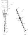
- FIGS. 2 and 3 there is shown an embodiment of a kit for treating glaucoma, which includes at least one hand-held instrument 101 ( FIG. 2 ) and at least one aqueous humor drainage device 201 ( FIG. 3 ).
- the instrument 101 has a needle body 103 that is inserted through ocular tissue into the anterior chamber 20 of the eye ( FIG. 1 ) to define a passage through the tissue leading into the anterior chamber 20.
- the needle body 103 has a maximal cross-sectional dimension (e.g., diameter D1 of FIG. 5 ) along its length.
- the proximal end of the needle body 103 is rigidly coupled to a hub 105.
- a handle 107 is rigidly coupled to the hub 105.
- the handle 107 is gripped by the fingers of the surgeon for manipulation of the needle body 103 as desired.
- a needle cover 109 can extend over the needle body 103 for safety.
- the needle body 103 can have a hollow-bore (or possibly a solid bore).
- the hub 105 and the handle 107 can be realized by a syringe body that includes a plunger that fits inside a tube as is well known.
- a solution can be loaded into the tube and pumped through the hollow- bore needle body 103 by hand manipulation of the plunger.
- the needle body may be bent into a more desirable shape to precisely place the needle tract, especially when the patient's nose is in the way of the needle handle.
- the aqueous humor drainage device 201 includes a flexible tube 203 that defines a duct 205 for diverting aqueous humor from the anterior chamber 20.
- the tube 203 has a proximal end 207 and distal end 209 opposite one another.
- the distal end 209 can have a tapered profile that facilitates insertion into the passage leading to the anterior chamber 20 formed by the needle body 103.
- the tube's outer surface 211 has a maximal cross-sectional dimension (e.g., outer diameter D2 of FIG. 7 ) that is less than the maximal cross-sectional dimension of the needle body 103 (e.g., diameter D1 of FIG. 5 ).
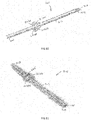
- the device 201 also includes first and second tabs or fins 213A, 213B that are spaced apart from the proximal and distal ends 207, 209 of the tube 203.
- the tabs 213A, 213B extend radially outward beyond the outer surface 211 of the tube 203 opposite one another on opposing sides of the tube 203.
- the first and second tabs 213A, 213B can be generally planar in form and lie in a common plane that extends transverse to the central axis of the tube 203 as best shown in FIG. 3 .
- the generally co- planar configuration of the tabs 213A, 213B when placed flat against the sclera of the eye, minimizes the profile of the device in order to reduce erosion and migration.
- the first and second tabs 213A, 213B can be mirror images of one another reflected about the central axis of the tube 203 as shown.
- Tab 213A defines an outer edge 215A
- tab 213B defines an outer edge 215B.
- the maximal distance between the outer edge 215A and the outer edge 215B define a maximal cross-sectional dimension that is greater that the maximal cross-sectional dimension of the needle body 103 (e.g., outer diameter D1 of FIG. 5 ).
- the tabs 213A, 213B are operably disposed within the passage defined by the needle body 103 and their dimensions cause the surrounding tissue to directly contact the tabs 213A, 213B in order to form a seal between the surrounding tissue and the tabs 213A, 213B.
- the seal surrounds the entire circumferential perimeter of the device defined by the tabs 213A, 213B and prevents leakage of aqueous humor through the space between the tube 203 and the surrounding tissue.
- the needle-defined passage can also be widened in the scleral area with the use of a sharp knife and associated stab wound. The widened part can be formed either before or after formation of the needle-defined passage.
- the tabs 213A, 213B can deform in the passage as they are inserted into the passage in response to forces applied by the surrounding tissue, and/or the surrounding tissue can deform (by compressing/stretching/thinning) as the tabs 213A, 213B are inserted into the passage.
- Such deformation is controlled by the maximal cross-sectional dimension of the tabs 213A, 213B relative to the cross-sectional dimension of the passage (as formed by the needle body 103 or stab wound) as well as the hardness of the material of the tabs 213A, 213B.
- the tabs 213A, 213B also act to fix the device 201 in place in the passage and minimize migration of the device 201 in both the proximal and distal directions.
- the outer edges 215A, 215B of the tabs 213A, 213B can have a tapered profile facing the distal end 209 as best shown on FIG. 3 . This tapered profile facilitates introduction of the tabs 213A, 213B into the passage formed by the needle body 103.
- the tabs 213A, 213B can have respective profiles that taper in the radial direction (i.e., the direction of the common plane of the tabs) transverse to and away from the central axis of the tube 203 as best shown in FIG. 3 .
- the outer surface 211 of the tube 203 has a maximal cross-sectional dimension (e.g., outer diameter D2) that is less than the maximal cross-sectional dimension of the needle body 103.
- the outer surface 211 can have an outer diameter D2 less than 0.4mm (such as on the order of 0.35mm) for a needle body 103 with a maximal cross-sectional dimension of 0.4mm.
- the duct 205 of the tube 203 is a simple constant-diameter lumen with a diameter in the range between 0.05mm and 0.15mm.
- This small duct diameter limits aqueous humor flow through the tube 203 and provides for control over IOP without the need for unidirectional valves or other structures (such as filters) that limit aqueous humor flow through the tube. More specifically, the diameter of the duct 205 alone controls the flow rate of aqueous humor through the duct 205 and thus controls the IOP of the patient.
- the appropriate duct diameter can vary among patients depending on the production rate of aqueous humor and the extent of clogging of the natural drainage paths of the patient and thus can be selected by the physician as desired.
- the instruments of a kit including at least one hand-held instrument 101 ( FIG. 2 ) and at least one aqueous humor drainage device 201 ( FIG. 3 ) as described herein, are housed in one or more enclosures, such as an instrument tray 401 as shown in FIG. 4 , that provides the surgeon easy access to the instruments as needed.
- the instrument tray 401 can be realized from suitable material (such as a thermoplastic) that is inexpensive and readily disposable for one-time use. Other materials (such as stainless steel and the like) suitable for non-disposable applications can also be used.
- the kit can include a plurality of hand-held instruments 101 ( FIG. 2 ) with needle bodies of different diameters and/or a plurality of aqueous humor drainage devices 201 ( FIG.
- tube ducts and/or tabs of different sizes for example, a plurality of devices 201 with different tab sizes that correspond to varying needle body diameters of the instruments 101 of the kit.
- knives of different diameters can be included in the kit as well as measuring devices, medications, sponges to apply medication, measuring devices, markers, syringes, rinsing fluid, trocars, inserters and the like.
- An inserter can be used to deploy the device 201 into the passage leading to the anterior chamber 20 formed by the needle body 103.
- the inserter can be realized by an apparatus similar to that described in U.S. Patents 7,431,709 , 7,594,899 , and 7,837,644 with one or two slots that accommodate the tabs 213A, 213B of the device 201.
- the inserter can be realized by a stylet and/or a trocar device as described below.
- the inserter can be part of the instrument kit housed in the tray 401.
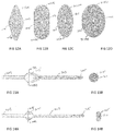
- FIG. 5 shows the dimensions of an exemplary embodiment of the needle body 103.
- the needle body 103 has an outer diameter D1 of 0.4 mm (i.e., 27 gauge).
- Other suitable outer diameters D1 can be in the range from 0.4mm (i.e., 27 gauge) to 0.635mm (i.e., 23 gauge).
- the needle body 103 can also be provided bent into a desirable shape to allow the needle to be inserted into the eye at an angle that, if not bent, would interfere with the patient's nose.
- FIGS. 6 and 7 shows the dimensions of an exemplary embodiment of an aqueous humor drainage device 201 for use with the needle body 103 of FIG. 5 .
- the tube 203 has a length of 8.5mm.
- the duct 205 has a diameter of 0.07mm.
- the outer surface 211 has a maximal cross sectional diameter (diameter D2) of 0.35mm, which is less than the outer diameter D1 of the needle body 103.
- the tabs 213A, 213B are spaced by 4.5mm from the distal end 209 of the tube 203 and spaced by 3mm from the proximal end 207 of the tube 203.
- the tabs 213A, 213B are generally planar in form and lie in a common plane that extends transverse to the central axis of the tube 203.
- the tabs 213A, 213B are mirror images of one another reflected about the central axis of the tube 203 as shown.
- the planar form of the first and second tabs 213A, 213B has a maximal thickness on the order of 0.35mm (i.e., the outer diameter D2 of the tube 203), a lengthwise dimension of 1mm parallel to the central axis of the tube 203, and a maximal cross-sectional dimension between the edges 215A, 215B of 1.1mm.
- the maximal cross-sectional dimension between the edges 215A, 215B can be in the range between 0.9mm and 1,5mm.
- Such maximal cross-sectional dimension is significantly larger than the outer diameter D1 of 0.4mm for the needle body 103 of FIG. 5 .
- FIGS. 8 to 14B illustrate alternate designs for the tabs of the implantable aqueous humor drainage device.
- the tabs 213A1, 213B1 have a profile that tapers in the radial direction transverse to the central axis of the tube 203 where the tapered radial surfaces of the tabs extend from a flat feature 217.
- the tabs 213A2, 213B2 are parts of a triangular wedged-shaped body 219 disposed along the lengthwise extent of the tube 203.
- the proximal walls 221 A, 22 IB of the wedge-shaped body 219 are oriented transverse to the central axis of the tube 203, which is intended to aid in reducing migration of the tube 203 in the proximal direction out of the passage formed by the instrument 101.
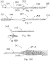
- the tabs 213A3, 213B3 have proximal walls 223A, 223B that are oriented transverse to the central axis of the tube 203, which is intended to aid in reducing migration of the tube 203 in the proximal direction out of the passage formed by the instrument 101.
- the tabs 213A4, 213B4 each have a curved wedge-shaped form. In the design of FIG.
- the tabs 213A5, 213B5 and tube 203 define a cross-sectional profile of rhombus with radiused comers (in particular, the rhombus profile tapers in the radial direction transverse to and away from the central axis of the tube 203).
- the tapered surfaces of the tabs 213A5, 213B5 extend from the annular surface of the tube 203 as shown.
- the tabs 213A6, 213B6 define a cross-sectional profile of an oblong with semicircular ends as shown.
- the tabs 213A6, 213B6 can define a cross-sectional profile of an oblong with semielliptical ends. In the design of FIG.
- the tabs 213A7, 213B7 define a cross-sectional profile of an ellipse whose boundary is offset radially from and surrounds the annular surface of the tube 203.
- the tabs 213A8, 213B8 define a cross-sectional profile of a larger radius ellipse (as compared to the elliptical profile of FIG. 12C ) whose boundary is offset radially from and surrounds the annular surface of the tube 203.
- a cork-like tab 213' is provided that extends circumferentially beyond the annular surface of the tube 203.
- the cork-like tab 213' has a cross-sectional profile of a circle as is evident from the view of FIG. 13B .
- a generally planar tab 213" is provided that extends circumferentially beyond the annular surface of the tube 203.
- the generally planar tab 213" has a cross-sectional oblong profile as is evident from the view of FIG. 14B .
- the outer surface(s) of the tab(s) of the device 201 can be blunt with rounded features as shown, and thus avoid any sharp comers and edges.
- the blunt outer surface(s) of the tab(s) is particularly suited to forming a seal to the surrounding tissue as described herein.
- a slit 225 is formed in the tabs 213A, 213B in a manner such that the slit 225 transects the lumen 205 of the aqueous humor drainage device 205.
- the slit 225 is positioned proximal to that part of the tabs 213A, 213B that forms the seal to the surrounding tissue (i.e., the blunt exterior edges of the tabs 213A, 213B at their maximal radial distance with respect to the central axis of the tube 203).
- the purpose of the slit 225 is twofold.
- the slit 225 can act as a pressure relief valve in the event the lumen 205 of the aqueous humor drainage device 205 becomes clogged downstream due to overgrowth of tissue in the bleb.
- the elastomeric nature of the aqueous humor drainage device 205 is such that as pressure builds up within the lumen 205, the slit 225 can deform into an open state where aqueous humor is released into the bleb thereby reducing pressure in the anterior chamber.
- the second advantage of the slit 225 is to deliberately accomplish the same purpose; that is to relieve pressure in the anterior chamber. In order to effectuate this release, the lumen 205 downstream from the slit 225 is sealed closed thereby forcing fluid to escape through the slit 225.
- the length and width of the slit 225 controls the pressure at which aqueous humor escapes and can be tailored to prevent hypotony.
- the aqueous humor escapes through the slit 225 and flows proximally in the space between the surrounding tissue and the outer surface of the proximal part of the tube 203. Fluid that escapes through the slit 225 will have its pressure dropped by both the narrow lumen 205 of the distal part of tube 203 as well as the slit 225.
- Periannular leakage of aqueous humor in the space between the surrounding tissue and the outer surface of the distal part of the tube 203 is blocked by the seal formed by the tabs 213A, 213B. More specifically, the blunt exterior edges of the tabs 213A, 213B at their maximal radial offset with respect to the central axis of the tube 203 forms a seal with the surrounding tissue that blocks such periannular leakage of aqueous humors.
- the aqueous humor drainage device 201 can be formed of a homogenous polymeric material.
- the homogenous polymeric material is a polyolefinic copolymer material having a triblock polymer backbone comprising polystyrene-polyisobutylene- polystyrene, which is herein referred to as "SIBS".
- SIBS can also be referred to as poly(styrene-b-isobutylene-b-styrene) where b stands for "block”.
- High molecular weight polyisobutylene (PIB) is a soft elastomeric material with a Shore hardness of approximately 10A to 30A.
- the SIBS material When copolymerized with polystyrene, it can be made at hardnesses ranging up to the hardness of polystyrene, which has a Shore hardness of 100D.
- the SIBS material can have a range of hardnesses from as soft as Shore 10A to as hard as Shore 100D. In this manner, the SIBS material can be adapted to have the desired elastomeric and hardness qualities.
- the SIBS material of the aqueous humor drainage device tube 201 has a hardness less than Shore 50A and greater than Shore 20A. Details of the SIBS material is set forth in U.S. Patent Nos.
- the SIBS material of the aqueous humor drainage device 201 may be polymerized under control means using carbocationic polymerization techniques such as those described in U.S. Patent Nos. 4,276,394 ; 4,316,973 ; 4,342,849 ; 4,910,321 ; 4,929,683 ; 4,946,899 ; 5,066,730 ; 5,122,572 ; and Re 34,640 , each herein incorporated by reference in its entirety.
- the amount of styrene in the copolymer material is preferably between 16 mole % and 30 mole % and most preferably between 20 mole % and 27 mole%.
- the styrene and isobutylene copolymer materials are preferably copolymerized in solvents.
- the glassy segment provides a hardener component for the elastomeric polyisobutylene.
- the glassy segment preferably does not contain any cleavable group which will release in the presence of body fluid inside the human eye and cause toxic side effects and cell encapsulation.
- the glassy segment can be a vinyl aromatic polymer (such as styrene, a-methylstyrene, or a mixture thereof), or a methacrylate polymer (such as methylmethacrylate, ethylmethacrylate, hydroxymethalcrylate, or a mixture thereof).
- Such materials preferably have a general block structure with a central elastomeric polyolefinic block and thermoplastic end blocks. Such materials have a general structure:
- polymeric materials can be used to provide aqueous drainage device 201 according to this invention.
- Exemplary materials are flexible materials that can conform to the surface of the eye and include but are not limited to silicone rubber, polyolefins (butyl rubber, polybutadiene, styrene-ethylene-propylene-butadiene, polyethylene, polypropylene, etc.) polyurethane (polyether urethanes, polycarbonate urethanes, polyurethanes containing polyisobutylene or other polyolefin soft segments, etc.); acrylics (polyacrylates, poly(2- hydroxyethylmethacrylate), etc.), fluoropolymers (PTFE, ePTFE, fluorosilicones, poly(-CH2- CF2)-, etc.), polyamides, hydrogels, biological based structures such as those comprised of collagen, elastin, etc.; and blends of all the above materials as well as soft foams and porous polymer materials can
- the entire aqueous humor drainage device 201 can be formed as a unitary part by molding the polymeric material. It is also contemplated that the polymeric material of the tabs 213A, 213B can be different from the polymeric material of the tube 203. This can be accomplished by insert molding techniques or other suitable thermoplastic forming techniques.
- the hardnesses of the tabs 213A, 213B can be the same as the tube 203, or they can differ from the tube 203. In one embodiment, the hardnesses of the tabs 213A, 213B are within the range between Shore 30A and Shore 80A.
- FIG. 15 there is shown the aqueous humor drainage device 201 implanted such that its distal end 209 is positioned within the anterior chamber 20 of the eye and its proximal end 207 is positioned in a pouch 300 formed between Tenon's membrane 36 and the sclera 26 ( FIG. 1 ).
- the pouch 300 defines a closed space between Tenon's membrane 36 and the sclera 26 ( FIG. 1 ).
- the duct 205 of the aqueous humor drainage device 201 shunts aqueous humor from the anterior chamber 20 to the pouch 300, which forms a shallow bleb.
- Aqueous humor is absorbed into the adjacent tissue and ends up in the venous system in the eye or in the tear film or simply evaporates from the outside of the conjunctiva once it reaches such.
- the pouch 300 can extend rearward from a location at or near the limbus to the posterior portion of the globe of the eye near or past the equator of the eye.
- the pouch 300 can be defined by making an incision through the conjunctiva or Tenon's membrane 36 to the surface of the sclera and then dissecting and separating Tenon's membrane 36 from the sclera 26 ( FIG. 1 ) over the area of the pouch 300. If the hinge from the pouch is in the fomix of the eye, this type of pouch is known as a fornix-based pouch. If the hinge is at the limbus and the incision in the fomix, this type of pouch is known as a limbus-based pouch.
- the distal end 209 of the aqueous humor drainage device 201 is inserted through a needle-formed passage through the angle 28 to the anterior chamber 20 of the eye.
- the device 201 is advanced further into the passage such that tabs 213A, 213B (only tab 213A is shown in FIG. 15 ) are positioned within the passage.
- the dimensions of the tabs 213A, 213B cause the surrounding tissue to directly contact the tabs 213A, 213B in order to form a seal between the surrounding tissue and the tabs 213A, 213B.
- the seal surrounds the entire circumferential perimeter of the device defined by the tabs 2213 A, 213B and prevents leakage of aqueous humor through the space between the tube 203 and the surrounding tissue.
- the tabs 213A, 213B can deform in the passage as they are inserted into the passage in response to forces applied by the surrounding tissue, and/or the surrounding tissue can deform (by stretching/thinning) as the tabs 213A, 213B are inserted into the passage. Such deformation is controlled by the maximal cross-sectional dimension of the tabs 213A, 213B relative to the cross-sectional dimension of the passage (as formed by the needle body 103) as well as the hardness of the material of the tabs 213A, 213B.
- the tabs 213A, 213B also act to fix the tube 203 in place in the passage and minimize migration of the tube 203 in both the proximal and distal directions. After proper positioning of the device 201, the pouch 300 is closed.
- a sponge, blotting paper or other suitable carrier loaded with an antiproliferative agent can be placed within the pouch 300 before it is closed.
- the anti-proliferative agent may be, for example, mitomycin C or 5-Fuorouracil or other antimetabolites or other suitable drug(s) or compound(s) that releases immediately or over time and functions to minimize fibrosis of the conjuctiva-sclera to Tenon's membrane, thereby maintaining the structure of the pouch 300 over an extended period of time.
- a collagen sponge or other space-filler structure or fluid can be placed in the pouch to prevent healing of the conjunctiva/Tenon's membrane to the sclera.
- Aqueous humor flows from the anterior chamber 20 through the duct 205 of the device 203 and into the sealed pouch 300.
- the sealed pouch 300 prevents bacteria from entering the device 201 and infecting the eye.
- Aqueous humor exiting the device 201 and entering the sealed pouch 300 creates a very shallow bleb.
- the bleb fluid may filter through the conjunctiva 30 ( FIG. 1 ) into the tears or evaporate therefrom, and the fluid may be absorbed through the lymphatic system and capillaries that interpenetrate the conjunctiva 30 ( FIG. 1 ).
- a fraction of the aqueous humor contained in the bleb may potentially seep through the permeable sclera 26 and be absorbed by the choroidal capillaries.
- the aqueous humor drainage device 201 can be implanted into the position shown in FIG. 15 utilizing the following method.
- the pouch 300 is made by dissecting the conjunctiva 30 at the limbus 32 in an incision area that is less than one quadrant using miniature scissors (Vannas scissors or similar) and dissecting and separating Tenon's membrane 36 from the sclera 26 over a few millimeters (a fornix-based flap). Then, holding the edge of the pouch 300 at its center with toothed forceps, the closed tips of a pair of blunt scissors (e.g. Westcott or similar) are slowly pushed downward toward the eye equator and opened up to separate (delaminate) Tenon's membrane 36 from the sclera 26.
- a pair of blunt scissors e.g. Westcott or similar
- the scissors are again closed; its tips pushed further forward and reopened to separate a larger area of Tenon's membrane 36.
- the process is repeated until the tips of the scissors are 17 to 20mm away from the limbus 32.
- the pouch 300 thusly created is larger at the equatorial base than at the limbal entry.
- the pouch 300 is formed adjacent to the limbus 32.
- a mark, centered in the middle of the conjunctival opening is made 2-3mm behind the limbus' edge using a blunt caliper.
- a tissue ink can be used on the tip of the caliper to increase contrast of the tissue mark.
- a handheld instrument 101 with a needle body 103 ( FIG. 1 ) is prepared and the tip of the needle body 103 is positioned at the mark made on the sclera.
- a surgical passage is fashioned to connect the scleral outer wall to the anterior chamber by pushing the needle body 103 in a plane such that the tip of the needle body 103 enters the eye through the angle 28 into the anterior chamber 20.
- the instrument 101 may be a syringe that holds a pharmacological solution, such as epinephrine or lidocain.
- the surgeon may elect to dispense the solution from the syringe into the anterior chamber 20 after introduction of the distal end of the syringe needle body 103 into the anterior chamber 20. After waiting for some time (e.g., a few seconds), the needle body 103 is slowly retracted.
- the aqueous humor drainage device 201 is inserted into the surgical passage into the position shown in FIG.
- the proximal end of the surgical passage can be enlarged at the scleral surface by means of a stab incision with a sharp knife (such as the knife of FIGS. 18A and 18B as described below) or by cutting the entrance to the sclera with the sharp edge of the needle body 103 as it is withdrawn.
- This stab incision can assist in the introduction of the tabs 213A, 213B of the device 201 into the surgical passage.
- the sharp knife is used to make a shallow slit or stab-wound into the sclera.
- a needle is then inserted into the slit and the surgical passage formed under the limbus.
- the tabs 213A, 213B are then tucked into the stab wound as described above.
- the dimensions of the tabs 213 A, 213B cause the surrounding ocular tissue of the surgical passage to directly contact the tabs 213A, 213B in order to form a seal between the surrounding ocular tissue and the tabs 213A, 213B.
- the seal surrounds the entire circumferential perimeter of the device defined by the tabs 213A, 213B and prevents leakage of aqueous humor through the space between the tube 203 and the surrounding ocular tissue of the surgical passage.
- the proximal end 207 of the tube 203 is positioned in the pouch 300 as shown in FIG. 15 .
- the aqueous humor drainage device 201 can be deployed from an inserter device similar to that described in U.S. Patents 7,431,709 , 7,594,899 , and 7,837,644 with one or two slots that accommodate the tabs 213A, 213B of the device 201.
- the aqueous humor drainage device 201 can be inserted into the passage using a stylet 301 and/or a trocar device 350 (or 410) as described below.
- the pouch 300 is then closed with sutures 304.
- sutures bipolar diathermy coagulation, laser welding or adhesives, such as cyanoacrylate, fibrin glue, etc. can be used to close the pouch 300.
- a trocar can be used to facilitate placement of the aqueous humor drainage device through the needle passage.
- the pouch 300 can also be created by dissection of the conjunctiva at the limbus and, starting at one edge of the dissection, cutting the conjuctival tissue posteriorly for about 3mm, thus creating a flap door.
- the device 201 is positioned in the surgical passage with the proximal end of the device in the pouch 300 as shown in FIG. 12 .
- the freed edge of the conjunctiva 30 is then juxtaposed about 2mm past its original position and held taut with a single suture, or a single laser weld, or a single-point bipolar diathermy coagulation, or with a single dot of adhesive.
- the edge of the conjunctiva 30 along the limbus 32 is never treated, but left intact to prevent tissue necrosis that engenders fibrosis.
- the comea-limbal epithelium cells will rapidly recover the wound edge (1 hour or less), sealing the conjunctival limbus.
- a sponge, blotting paper or other suitable carrier loaded with one or more therapeutic agents can be placed within the pouch 300 before it is closed.
- Such therapeutic agent(s) release over time and minimizes fibrosis of Tenon's membrane to the sclera, thereby preventing re-lamination and closure of the bleb space (the interior space of the closed pouch 300 that surrounds the proximal end 207 of the tube 203).
- the therapeutic agents(s) can include cytostatic agents (i.e., anti-proliferation agents that prevent or delay cell division, for example, by inhibiting replication of DNA, and/or by inhibiting spindle fiber formation, and/or by inhibiting cell migration) or other agents that minimize fibrosis or blood clots. Examples of such therapeutic agents are described below.
- FIG. 16 shows the aqueous humor drainage device 201 with a stylet 301 that is removably inserted into the lumen 205 of the proximal portion 209 of the device 201 to aid in the insertion of the device 201 into the needle-formed passage.
- the proximal end of the stylet 301 is bent in a pig-tail configuration 302 to enable the surgeon to grip the stylet 301 and remove it from the lumen 205 of the aqueous humor drainage device 201 once it is in place.
- FIG. 17 shows another embodiment of the stylet 301 where a larger tube 303 is crimped onto the proximal end of the stylet to facilitate gripping and removal.
- FIGS. 18A and 18B show a hand-held knife 340 that can be used to make the stab wound in the sclera to further secure the elements of the aqueous humor drainage device 201 in the sclera.
- the Diameter "a" of the knife edge 341 is less than the maximal cross-sectional diameter of the tabs 213A, 213B of the device 201 in order to enable a snug fit of the tabs 213A, 213B into the stab wound.
- the length b of the knife edge 341 can be approximately the same dimension as the dimension a.
- FIG. 18C shows an embodiment of a hand-held instrument 342 that includes a distal needle body 343 extending from a flat blade portion with cutting surfaces 344A, 344B.
- the needle body 343 creates the passage leading through the sclera and the cutting surfaces 344A, 344B create a widened stab wound in the sclera in one motion of the surgeon's hand.
- a trocar 350 which includes a conduit 352 with a skived slot 351 ( FIG. 19 ) can be provided.
- the conduit 352 is sized to receive the needle body 103 as well as the tube 203 of the aqueous humor drainage device 201.
- the trocar 350 is placed over the needle body 103 to provide the assembly 360 shown in FIG. 20A.
- 20B to 20E illustrate the function of the trocar 350.
- the assembly 360 is inserted into the needle- formed passage through the sclera 400 as is shown in FIG. 20B .
- the needle body 103 is then removed from the assembly leaving trocar 350 in place as shown in FIG. 20C .
- the aqueous humor drainage device 201 is then fed through the trocar 350 as shown in FIG. 20D .
- the trocar 350 is then removed leaving the aqueous humor drainage device 201 behind inside the needle- formed passage as shown in FIG. 20E .
- the elastic nature of the tube 203 of the device 201 allows the tube 203 to bend and deform such that it passes through the slot 351 of the trocar 350 as the trocar 305 is removed.
- the position of the aqueous humor drainage device 201 within the passage can then be adjusted by the surgeon (for example, by further inserting the device 201 into the passage) such that the tabs 213A, 213B interface to the tissue wall of the passage and provide a seal between the tissue and the device 201. In this position, the tabs 213A, 213B also act to fixate the device in the passage.
- FIG. 21 shows another embodiment of a trocar 410, which includes a conduit 412 with a slot 411 which is skived partway along the conduit 412. A section of the lid of the skived slot (e.g., tab 413) remains integral with the tube as is shown.
- the conduit 412 is sized to receive the needle body 103 as well as the tube 203 of the aqueous humor drainage device 201.
- the trocar 410 is placed over the needle body 103 with the hub 415 butting against the proximal end of conduit 412 to provide the assembly shown in FIG. 22A.
- FIGS. 22B to 22D illustrate the function of the trocar 410. The assembly is inserted into the needle-formed passage through the sclera 400 as is shown in FIG. 22B .
- the abutment of conduit 412 to the hub 415 prevents the trocar 410 from slipping backward on the needle body as it is inserted through tissue.
- the needle body 103 is removed from trocar 410 as shown in FIG. 22C , which is facilitated by gripping tab 413 with a forceps as needle 103 is pulled out of trocar 410.
- the trocar 410 is cut at line 420 (for example, with scissors) and the proximal portion of the conduit 412 with tab 413 is discarded as shown in FIG. 22D .
- the aqueous humor drainage device 201 is then fed through the remaining trocar portion 421 into the needle-formed passage in a manner similar to the method described above in conjunction with FIG. 20D .
- the trocar portion 421 is then removed leaving the aqueous humor drainage device 201 behind inside the needle-formed passage as shown in FIG. 20E .
- the elastic nature of the tube 203 of the device 201 allows the tube 203 to bend and deform such that it passes through the slot 411 of the trocar portion 421 as the trocar portion 421 is removed.
- the position of the aqueous humor drainage device 201 within the passage can then adjusted by the surgeon (for example, by further inserting the device 201 into the passage) such that the tabs 213A, 213B interface to the tissue wall of the passage and provide a seal between the tissue and the device 201. In this position, the tabs 213A, 213B also act to fixate the device in the passage.
- Another embodiment contemplated by this invention is to first form the needle tract under the limbus with needle 103, then pre-load tube 203 of the aqueous humor drainage device 201 into trocar 350 or 410 and then push the assembly through the needle tract. The trocar is then removed from the needle tract as explained above.
- the trocars of FIGS. 19 and 21 can be made from a stiff thin material preferably polyimide.
- Other materials that may function in this capacity are PEEK, PEEKEK, polyurethane, polypropylene, high molecular weight polyethylene, Nylon, fluoropolymers, etc.
- the material forming the trocars can be made from metal (preferably well-known metals used in medical devices such as stainless steel, titanium, Nitinol, etc.).
- the main requirement is that when the trocar is inserted through tissue that it not buckle.
- the wall thickness of the trocar should be between 0.0002" and 0.003"; preferably between 0.001 and 0.003".
- the inner diameter of the trocar should be equal to or larger than the diameter of the needle body 103; that is, if inserted over a needle, or equal to or larger than the flexible tube 102 if the trocar is pre-loaded with the aqueous drainage device.
- the polymeric aqueous humor drainage device 201 (or parts thereof) can be loaded with one or more therapeutic agents that release over time and minimize fibrosis of the Tenon's membrane to the sclera, thereby preventing re-lamination and closing of the bleb space.
- the therapeutic agents(s) loaded into the device 100 can include cytostatic agents (i.e., antiproliferation agents that prevent or delay cell division, for example, by inhibiting replication of DNA, and/or by inhibiting spindle fiber formation, and/or by inhibiting cell migration) or other agents that minimize fibrosis or blood clots. Examples of such therapeutic agents follow.
- therapeutic agents include the following: Visudyne, Lucentis (rhuFab V2 AMD), Combretastatin A4 Prodrug, SnET2, H8, VEGF Trap, Cand5, LS 11 (Taporfin Sodium), AdPEDF, RetinoStat, Integrin, Panzem, Retaane, Anecortave Acetate, VEGFR-1 mRNA, ARGENT cell-signaling technology, Angiotensin II Inhibitor, Accutane for Blindness, Macugen (PEGylated aptamer), PTAMD, Optrin, AK-1003, NX 1838, Antagonists of avb3 and 5, Neovastat, Eos 200-F and any other VEGF inhibitor.
- therapeutic agents can be used such as: mitomycin C, 5-fluorouracil, corticosteroids (corticosteroid triamcinolone acetonide is most common), modified toxins, methotrexate, adriamycin, radionuclides (e.g., such as disclosed in U.S. Patent No.
- protein kinase inhibitors including staurosporin, which is a protein kinase C inhibitor, as well as a diindoloalkaloids and stimulators of the production or activation of TGF-beta, including tamoxifen and derivatives of functional equivalents, e.g., plasmin, heparin, compounds capable of reducing the level or inactivating the lipoprotein Lp(a) or the glycoprotein apolipoprotein(a) thereof), nitric oxide releasing compounds (e.g., nitroglycerin) or analogs or functional equivalents thereof, paclitaxel or analogs or functional equivalents thereof (e.g., taxotere or an agent based on Taxol®, whose active ingredient is paclitaxel), inhibitors of specific enzymes (such as the nuclear enzyme DNA topoisomerase II and DAN polymerase, RNA polyermase, adenl), inhibitors of specific enzymes (such as the nuclear enzyme DNA topoisome
- therapeutic agents include the following: peptidic or mimetic inhibitors, such as antagonists, agonists, or competitive or non-competitive inhibitors of cellular factors that may trigger proliferation of cells or pericytes (e.g., cytokines (for example, interleukins such as IL-1), growth factors (for example, PDGF, TGF-alpha or -beta, tumor necrosis factor, smooth muscle- and endothelioal- derived growth factors such as endothelin or FGF), homing receptors (for example, for platelets or leukocytes), and extracellular matrix receptors (for example, integrins).
- cytokines for example, interleukins such as IL-1
- growth factors for example, PDGF, TGF-alpha or -beta, tumor necrosis factor, smooth muscle- and endothelioal- derived growth factors such as endothelin or FGF
- homing receptors for example, for platelets or leukocytes
- useful therapeutic agents in the category of agents that address cell proliferation include: sub fragments of heparin, triazolopyrimidine (for example, trapidil, which is a PDGF antagonist), lovastatin; and prostaglandins El or 12.
- a therapeutic agent of interest can be provided at the same time as the polymer from which the device 201 is realized, for example, by adding it to a polymer melt during thermoplastic processing or by adding it to a polymer solution during solvent-based processing.
- a therapeutic agent can be provided after formation of the device or device portion.
- the therapeutic agent can be dissolved in a solvent that is compatible with both the device polymer and the therapeutic agent.
- the device polymer is at most only slightly soluble in this solvent. Subsequently, the solution is contacted with the device or device portion such that the therapeutic agent is loaded (e.g., by leaching/diffusion) into the copolymer.
- the device or device portion can be immersed or dipped into the solution, the solution can be applied to the device or component, for example, by spraying, printing dip coating, immersing in a fluidized bed and so forth.
- the device or component can subsequently be dried, with the therapeutic agent remaining therein.
- the therapeutic agent may be provided within a matrix comprising the polymer of the device 201.
- the therapeutic agent can also be covalently bonded, hydrogen bonded, or electrostatically bound to the polymer of the device 201.
- nitric oxide releasing functional groups such as S-nitroso-thiols can be provided in connection with the polymer, or the polymer can be provided with charged functional groups to attach therapeutic groups with oppositely charged functionalities.
- the therapeutic agent can be precipitated onto one or more surfaces of the device 201 (or device portion). These one or more surface(s) can be subsequently covered with a coating of polymer (with or without additional therapeutic agent) as described above.
- the polymer is "loaded" with therapeutic agent, it is meant that the therapeutic agent is associated with the polymer in a fashion like those discussed above or in a related fashion.
- a binder may be useful for adhesion to a substrate.
- materials appropriate for binders in connection with the present invention include silanes, titanates, isocyanates, carboxyls, amides, amines, acrylates hydroxyls, and epoxides, including specific polymers such as EVA, polyisobutylene, natural rubbers, polyurethanes, siloxane coupling agents, ethylene and propylene oxides.
- the polymer of the device 201 (which may or may not contain a therapeutic agent) with an additional polymer layer (which may or may not contain a therapeutic agent).
- This layer may serve, for example, as a boundary layer to retard diffusion of the therapeutic agent and prevent a burst phenomenon whereby much of the agent is released immediately upon exposure of the device or device portion to the implant site.
- the material constituting the coating, or boundary layer may or may not be the same polymer as the loaded polymer.
- the barrier layer may also be a polymer or small molecule from the following classes: polycarboxylic acids, including polyacrylic acid; cellulosic polymers, including cellulose acetate and cellulose nitrate; gelatin; polyvinylpyrrolidone; cross-linked polyvinylpyrrolidone; polyanhydrides including maleic anhydride polymers; polyamides; polyvinyl alcohols; copolymers of vinyl monomers such as EVA (ethylene-vinyl acetate copolymer); polyvinyl ethers; polyvinyl aromatics; polyethylene oxides; glycosaminoglycans; polysaccharides; polyesters including polyethylene terephthalate; polyacrylamides; polyethers; polyether sulfone; polycarbonate; polyalkylenes including polypropylene, polyethylene and high molecular weight polyethylene; halogenated polyalkylenes including polytetrafluoroethylene; polyurethanes; polyorthoesters;
- Copolymers and mixtures of the above are also contemplated.
- aqueous humor drainage device 201 or device portion
- blends by adding one or more of the above or other polymers to a block copolymer. Examples include the following:
- the release rate of therapeutic agent from the therapeutic-agent-loaded polymers of the present invention can be varied in a number of ways. Examples include:
- one or more of the therapeutic drug agents described herein may be injected into the pouch 300 at the time of surgery.
Claims (9)
- Dispositif implantable (201) pour le traitement d'une pression oculaire élevée dans la chambre antérieure de l'œil, le dispositif comprenant :un tube flexible (203) ; etun moyen de scellement de tissu,dans lequel ledit tube (203) définit un conduit (205) pour dévier l'humeur aqueuse de la chambre antérieure, ledit tube ayant une extrémité proximale (207) et une extrémité distale (209) opposées l'une à l'autre et une surface externe (211) ayant une première dimension en coupe transversale maximale, etdans lequel ledit moyen de scellement de tissu comporte au moins un élément (213A, 213B) qui est espacé desdites extrémités proximale et distale (207, 209) dudit tube, ledit au moins un élément s'étendant radialement vers l'extérieur au-delà de ladite surface externe (211) dudit tube et ayant une deuxième dimension en coupe transversale maximale supérieure à ladite première dimension en coupe transversale maximale,caractérisé en ce queladite deuxième dimension en coupe transversale maximale est définie par au moins une surface émoussée,dans lequel ledit au moins un élément (213A, 213B) a une partie distale effilée, etdans lequel :
ledit au moins un élément comporte des première et deuxième languettes (213A, 213B) qui s'étendent radialement depuis ledit tube (203) sur des côtés opposés dudit tube, ladite première languette (213A) définissant un premier bord extérieur (215A), ladite deuxième languette (213B) définissant un deuxième bord extérieur (215B), dans lequel ladite deuxième dimension en coupe transversale maximale est définie par la distance maximale entre ledit premier bord extérieur (215A) et ledit deuxième bord extérieur (215B). - Dispositif selon la revendication 1, dans lequel :
lesdites première et deuxième languettes (213A, 213B) sont configurées pour se déformer dans un passage tissulaire menant à la chambre antérieure de l'œil à mesure qu'elles sont insérées dans le passage tissulaire en réponse à des forces appliquées par le tissu oculaire environnant du passage tissulaire. - Dispositif selon la revendication 1 ou 2, dans lequel :
lesdites première et deuxième languettes (213A, 213B) ont une dureté se trouvant dans une plage comprise entre Shore 30A et Shore 80A. - Dispositif selon l'une quelconque des revendications 1 à 3, dans lequel :
ledit premier bord extérieur (215A) et ledit deuxième bord extérieur (215B) ont un profil effilé faisant face à l'extrémité distale (209) dudit tube. - Dispositif selon l'une quelconque des revendications 1 à 4, dans lequel :ladite première dimension en coupe transversale maximale n'est pas supérieure à 0,4 mm ; etladite deuxième dimension en coupe transversale maximale est d'au moins 0,9 mm.
- Dispositif selon l'une quelconque des revendications 1 à 5, dans lequel :
ledit dispositif (201) est une pièce moulée unitaire réalisée à partir d'un matériau polymère choisi dans le groupe constitué d'un matériau SIBS, d'un caoutchouc de silicone, d'un polymère polyoléfine, d'un polymère polyuréthane, d'un polymère acrylique, d'un polymère fluoré, d'un polymère polyamide, d'un polymère hydrogel, d'un structure à base biologique, d'un matériau en mousse polymère souple, d'un matériau polymère poreux et des combinaisons de ceux-ci. - Dispositif selon la revendication 6, dans lequel :
le matériau polymère pour au moins une partie dudit dispositif est chargé d'au moins un agent thérapeutique. - Dispositif selon l'une quelconque des revendications 1 à 7, dans lequel :
ladite au moins une surface émoussée a un profil oblong en coupe transversale. - Dispositif selon l'une quelconque des revendications 1 à 7, dans lequel :
ladite au moins une surface émoussée a un profil en coupe transversale d'une ellipse ou d'un cercle.
Priority Applications (2)
| Application Number | Priority Date | Filing Date | Title |
|---|---|---|---|
| EP21186352.7A EP3919030A1 (fr) | 2012-01-12 | 2013-01-10 | Dispositif implantable pour le traitement du glaucome |
| PL18152701T PL3329884T3 (pl) | 2012-01-12 | 2013-01-10 | Wszczepialne urządzenie do leczenia jaskry |
Applications Claiming Priority (3)
| Application Number | Priority Date | Filing Date | Title |
|---|---|---|---|
| US13/348,931 US9101444B2 (en) | 2012-01-12 | 2012-01-12 | Method, surgical kit and device for treating glaucoma |
| PCT/US2013/020920 WO2013147978A2 (fr) | 2012-01-12 | 2013-01-10 | Procédé, kit chirurgical et dispositif pour le traitement du glaucome |
| EP13769427.9A EP2802300B1 (fr) | 2012-01-12 | 2013-01-10 | Kit chirurgical et dispositif pour le traitement du glaucome |
Related Parent Applications (2)
| Application Number | Title | Priority Date | Filing Date |
|---|---|---|---|
| EP13769427.9A Division EP2802300B1 (fr) | 2012-01-12 | 2013-01-10 | Kit chirurgical et dispositif pour le traitement du glaucome |
| EP13769427.9A Division-Into EP2802300B1 (fr) | 2012-01-12 | 2013-01-10 | Kit chirurgical et dispositif pour le traitement du glaucome |
Related Child Applications (2)
| Application Number | Title | Priority Date | Filing Date |
|---|---|---|---|
| EP21186352.7A Division EP3919030A1 (fr) | 2012-01-12 | 2013-01-10 | Dispositif implantable pour le traitement du glaucome |
| EP21186352.7A Division-Into EP3919030A1 (fr) | 2012-01-12 | 2013-01-10 | Dispositif implantable pour le traitement du glaucome |
Publications (2)
| Publication Number | Publication Date |
|---|---|
| EP3329884A1 EP3329884A1 (fr) | 2018-06-06 |
| EP3329884B1 true EP3329884B1 (fr) | 2021-08-25 |
Family
ID=48780459
Family Applications (3)
| Application Number | Title | Priority Date | Filing Date |
|---|---|---|---|
| EP13769427.9A Active EP2802300B1 (fr) | 2012-01-12 | 2013-01-10 | Kit chirurgical et dispositif pour le traitement du glaucome |
| EP18152701.1A Active EP3329884B1 (fr) | 2012-01-12 | 2013-01-10 | Dispositif implantable pour le traitement du glaucome |
| EP21186352.7A Pending EP3919030A1 (fr) | 2012-01-12 | 2013-01-10 | Dispositif implantable pour le traitement du glaucome |
Family Applications Before (1)
| Application Number | Title | Priority Date | Filing Date |
|---|---|---|---|
| EP13769427.9A Active EP2802300B1 (fr) | 2012-01-12 | 2013-01-10 | Kit chirurgical et dispositif pour le traitement du glaucome |
Family Applications After (1)
| Application Number | Title | Priority Date | Filing Date |
|---|---|---|---|
| EP21186352.7A Pending EP3919030A1 (fr) | 2012-01-12 | 2013-01-10 | Dispositif implantable pour le traitement du glaucome |
Country Status (13)
| Country | Link |
|---|---|
| US (6) | US9101444B2 (fr) |
| EP (3) | EP2802300B1 (fr) |
| JP (4) | JP6063959B2 (fr) |
| KR (1) | KR102021275B1 (fr) |
| CN (2) | CN107252382B (fr) |
| AU (2) | AU2013240553B2 (fr) |
| BR (1) | BR112014016938B1 (fr) |
| CA (2) | CA3053965C (fr) |
| DK (2) | DK2802300T3 (fr) |
| ES (2) | ES2887022T3 (fr) |
| HK (1) | HK1256693A1 (fr) |
| PL (2) | PL2802300T3 (fr) |
| WO (1) | WO2013147978A2 (fr) |
Cited By (1)
| Publication number | Priority date | Publication date | Assignee | Title |
|---|---|---|---|---|
| US11766355B2 (en) | 2020-03-19 | 2023-09-26 | Shifamed Holdings, Llc | Intraocular shunts with low-profile actuation elements and associated systems and methods |
Families Citing this family (86)
| Publication number | Priority date | Publication date | Assignee | Title |
|---|---|---|---|---|
| EP1477146B1 (fr) | 1999-04-26 | 2009-08-26 | Glaukos Corporation | Dispositif de dérivation pour traitement du glaucome |
| US6638239B1 (en) | 2000-04-14 | 2003-10-28 | Glaukos Corporation | Apparatus and method for treating glaucoma |
| US7867186B2 (en) | 2002-04-08 | 2011-01-11 | Glaukos Corporation | Devices and methods for treatment of ocular disorders |
| WO2002080811A2 (fr) | 2001-04-07 | 2002-10-17 | Glaukos Corporation | Stent de glaucome et procedes destines au traitement d'un glaucome |
| US7431710B2 (en) | 2002-04-08 | 2008-10-07 | Glaukos Corporation | Ocular implants with anchors and methods thereof |
| US7331984B2 (en) | 2001-08-28 | 2008-02-19 | Glaukos Corporation | Glaucoma stent for treating glaucoma and methods of use |
| US20120123316A1 (en) | 2010-11-15 | 2012-05-17 | Aquesys, Inc. | Intraocular shunts for placement in the intra-tenon's space |
| US8852256B2 (en) | 2010-11-15 | 2014-10-07 | Aquesys, Inc. | Methods for intraocular shunt placement |
| US10085884B2 (en) | 2006-06-30 | 2018-10-02 | Aquesys, Inc. | Intraocular devices |
| US8721702B2 (en) | 2010-11-15 | 2014-05-13 | Aquesys, Inc. | Intraocular shunt deployment devices |
| US8663303B2 (en) | 2010-11-15 | 2014-03-04 | Aquesys, Inc. | Methods for deploying an intraocular shunt from a deployment device and into an eye |
| AU2007319383A1 (en) | 2006-11-10 | 2008-05-22 | Glaukos Corporation | Uveoscleral shunt and methods for implanting same |
| US20170360609A9 (en) | 2007-09-24 | 2017-12-21 | Ivantis, Inc. | Methods and devices for increasing aqueous humor outflow |
| US10842671B2 (en) | 2010-11-15 | 2020-11-24 | Aquesys, Inc. | Intraocular shunt placement in the suprachoroidal space |
| US8765210B2 (en) | 2011-12-08 | 2014-07-01 | Aquesys, Inc. | Systems and methods for making gelatin shunts |
| US10080682B2 (en) | 2011-12-08 | 2018-09-25 | Aquesys, Inc. | Intrascleral shunt placement |
| US9808373B2 (en) | 2013-06-28 | 2017-11-07 | Aquesys, Inc. | Intraocular shunt implantation |
| US9610195B2 (en) | 2013-02-27 | 2017-04-04 | Aquesys, Inc. | Intraocular shunt implantation methods and devices |
| US8852136B2 (en) | 2011-12-08 | 2014-10-07 | Aquesys, Inc. | Methods for placing a shunt into the intra-scleral space |
| US9101444B2 (en) * | 2012-01-12 | 2015-08-11 | Innfocus, Inc. | Method, surgical kit and device for treating glaucoma |
| US10342700B2 (en) * | 2012-02-22 | 2019-07-09 | Ira H. Schachar | Device and method for treatment of retinal detachment and other maladies of the eye |
| JP6465490B2 (ja) | 2012-03-26 | 2019-02-06 | グローコス コーポレーション | インプラント送達装置 |
| US9358156B2 (en) | 2012-04-18 | 2016-06-07 | Invantis, Inc. | Ocular implants for delivery into an anterior chamber of the eye |
| WO2014085450A1 (fr) | 2012-11-28 | 2014-06-05 | Ivantis, Inc. | Appareil de délivrance d'implants oculaires dans une chambre antérieure de l'œil |
| DE102013018008A1 (de) * | 2012-12-19 | 2014-06-26 | Ophtalmic Implants Private Limited | Trokar und integriertes Trokarnadelsystem für die Glaukomdrainagechirurgie |
| US9125723B2 (en) | 2013-02-19 | 2015-09-08 | Aquesys, Inc. | Adjustable glaucoma implant |
| US10159600B2 (en) | 2013-02-19 | 2018-12-25 | Aquesys, Inc. | Adjustable intraocular flow regulation |
| US10517759B2 (en) | 2013-03-15 | 2019-12-31 | Glaukos Corporation | Glaucoma stent and methods thereof for glaucoma treatment |
| US9592151B2 (en) | 2013-03-15 | 2017-03-14 | Glaukos Corporation | Systems and methods for delivering an ocular implant to the suprachoroidal space within an eye |
| NZ719850A (en) | 2013-11-14 | 2017-03-31 | Aquesys Inc | Intraocular shunt inserter |
| US9044301B1 (en) | 2013-11-25 | 2015-06-02 | Innfocus, Inc. | Methods, systems and devices for treating glaucoma |
| US10010447B2 (en) * | 2013-12-18 | 2018-07-03 | Novartis Ag | Systems and methods for subretinal delivery of therapeutic agents |
| JP6580600B2 (ja) * | 2014-02-24 | 2019-09-25 | シンガポール国立大学National University Of Singapore | 眼内流体排出器具及びその製造方法 |
| US9427558B2 (en) | 2014-03-17 | 2016-08-30 | Arkis Biosciences | Tunneling guidewire |
| AU2015266850B2 (en) | 2014-05-29 | 2019-12-05 | Glaukos Corporation | Implants with controlled drug delivery features and methods of using same |
| WO2016011056A1 (fr) | 2014-07-14 | 2016-01-21 | Ivantis, Inc. | Système et procédé de pose d'implant oculaire |
| CN204050005U (zh) | 2014-09-09 | 2014-12-31 | 赵潺 | 一次性负压前房穿刺针 |
| CN113208809A (zh) * | 2014-12-31 | 2021-08-06 | 迈克罗欧普提克斯股份有限公司 | 青光眼治疗装置和方法 |
| MA42406A (fr) | 2015-06-03 | 2018-05-16 | Aquesys Inc | Mise en place de shunt intraoculaire ab externo |
| JP6748122B2 (ja) * | 2015-06-26 | 2020-08-26 | インフォーカス,インコーポレイテッド | 緑内障デバイス送達システム及び経結膜の送達方法 |
| JP6837475B2 (ja) | 2015-08-14 | 2021-03-03 | イバンティス インコーポレイテッド | 圧力センサを備えた眼用インプラントおよび送達システム |
| US11925578B2 (en) | 2015-09-02 | 2024-03-12 | Glaukos Corporation | Drug delivery implants with bi-directional delivery capacity |
| AU2016331925B2 (en) | 2015-09-30 | 2021-04-22 | Microoptx Inc. | Dry eye treatment devices and methods |
| US11938058B2 (en) | 2015-12-15 | 2024-03-26 | Alcon Inc. | Ocular implant and delivery system |
| USD786433S1 (en) | 2016-01-29 | 2017-05-09 | Arkis Biosciences Inc. | Trocar |
| CN105997341B (zh) * | 2016-04-21 | 2019-03-08 | 温州医科大学附属眼视光医院 | 一种青光眼内引流替代仿生支架的制备及其使用方法 |
| CA3024891A1 (fr) | 2016-05-31 | 2017-12-07 | Qura, Inc. | Capteurs de pression intraoculaire implantables et procedes d'utilisation |
| WO2017210627A1 (fr) | 2016-06-02 | 2017-12-07 | Aquesys, Inc. | Administration intraoculaire de médicaments |
| CN106139265A (zh) * | 2016-07-14 | 2016-11-23 | 遵义医学院附属医院 | 胸腔引流置入装置 |
| TW201811280A (zh) * | 2016-09-01 | 2018-04-01 | 英福卡斯公司 | 用於插入青光眼分流器之工具 |
| USD835777S1 (en) | 2016-10-27 | 2018-12-11 | Arkis Biosciences Inc. | Guidewire stylette |
| USD822830S1 (en) | 2017-04-20 | 2018-07-10 | Arkis Biosciences Inc. | Catheter retention device |
| CA3077101A1 (fr) | 2017-06-13 | 2018-12-20 | Innfocus, Inc. | Systemes, methodes et appareils pour le traitement du glaucome |
| US11116625B2 (en) | 2017-09-28 | 2021-09-14 | Glaukos Corporation | Apparatus and method for controlling placement of intraocular implants |
| CN113893085A (zh) | 2017-10-06 | 2022-01-07 | 格劳科斯公司 | 用于递送多个眼部植入物的系统和方法 |
| USD846738S1 (en) | 2017-10-27 | 2019-04-23 | Glaukos Corporation | Implant delivery apparatus |
| US11246753B2 (en) | 2017-11-08 | 2022-02-15 | Aquesys, Inc. | Manually adjustable intraocular flow regulation |
| US20200390600A1 (en) * | 2018-02-19 | 2020-12-17 | Singapore Health Services Pte Ltd | Method and apparatus for shearing tissue at a target surgical site |
| AU2019223946B2 (en) * | 2018-02-22 | 2021-05-20 | Alcon Inc. | Ocular implant and delivery system |
| US10952898B2 (en) | 2018-03-09 | 2021-03-23 | Aquesys, Inc. | Intraocular shunt inserter |
| US11135089B2 (en) | 2018-03-09 | 2021-10-05 | Aquesys, Inc. | Intraocular shunt inserter |
| CN108433748A (zh) * | 2018-04-11 | 2018-08-24 | 中山大学中山眼科中心 | 带阀门的液态标本的采集装置 |
| CN110711075A (zh) * | 2018-07-11 | 2020-01-21 | 吴坚 | 一种泪小管栓塞 |
| US11173067B2 (en) | 2018-09-07 | 2021-11-16 | Vialase, Inc. | Surgical system and procedure for precise intraocular pressure reduction |
| US11246754B2 (en) | 2018-07-16 | 2022-02-15 | Vialase, Inc. | Surgical system and procedure for treatment of the trabecular meshwork and Schlemm's canal using a femtosecond laser |
| US11110006B2 (en) | 2018-09-07 | 2021-09-07 | Vialase, Inc. | Non-invasive and minimally invasive laser surgery for the reduction of intraocular pressure in the eye |
| US10821024B2 (en) | 2018-07-16 | 2020-11-03 | Vialase, Inc. | System and method for angled optical access to the irido-corneal angle of the eye |
| JP7022030B2 (ja) | 2018-08-08 | 2022-02-17 | Kddi株式会社 | コンテンツ配信ネットワークの転送装置 |
| CN109172129A (zh) * | 2018-09-29 | 2019-01-11 | 王丽强 | 青光眼阀引流装置 |
| ES2882522T3 (es) | 2018-12-12 | 2021-12-02 | Ajl Ophthalmic S A | Dispositivo de implante de glaucoma |
| CN113453648A (zh) * | 2019-02-27 | 2021-09-28 | 英福卡斯公司 | 青光眼装置插入器 |
| US11234866B2 (en) * | 2019-04-19 | 2022-02-01 | Elios Vision, Inc. | Personalization of excimer laser fibers |
| WO2021000255A1 (fr) * | 2019-07-02 | 2021-01-07 | 北京华视诺维医疗科技有限公司 | Dispositif de collecte d'humeur aqueuse |
| JP2022552284A (ja) | 2019-10-10 | 2022-12-15 | シファメド・ホールディングス・エルエルシー | 流量調整可能な緑内障用シャントならびに関連システム及び方法 |
| KR102390116B1 (ko) * | 2019-11-19 | 2022-04-25 | 주식회사 마이크로트 | 쉽고 안전한 방법으로 안압을 내릴 수 있는 안질환용 임플란트 장치 |
| CN115379818A (zh) | 2020-01-23 | 2022-11-22 | 施菲姆德控股有限责任公司 | 可调节流量的青光眼分流器及相关系统和方法 |
| US11564567B2 (en) | 2020-02-04 | 2023-01-31 | Vialase, Inc. | System and method for locating a surface of ocular tissue for glaucoma surgery based on dual aiming beams |
| CN115426988A (zh) | 2020-02-14 | 2022-12-02 | 施菲姆德控股有限责任公司 | 具有基于旋转的流动控制组件的分流系统,以及相关系统和方法 |
| WO2021168130A1 (fr) | 2020-02-18 | 2021-08-26 | Shifamed Holdings, Llc | Shunts de glaucome à écoulement réglable ayant des éléments de commande d'écoulement disposés de manière non linéaire, et systèmes et procédés associés |
| US11612315B2 (en) | 2020-04-09 | 2023-03-28 | Vialase, Inc. | Alignment and diagnostic device and methods for imaging and surgery at the irido-corneal angle of the eye |
| CN115867237A (zh) | 2020-04-16 | 2023-03-28 | 施菲姆德控股有限责任公司 | 可调节青光眼治疗装置及相关联系统和方法 |
| WO2022150684A1 (fr) | 2021-01-11 | 2022-07-14 | Ivantis, Inc. | Systèmes et procédés d'administration viscoélastique |
| US11865283B2 (en) | 2021-01-22 | 2024-01-09 | Shifamed Holdings, Llc | Adjustable shunting systems with plate assemblies, and associated systems and methods |
| CA3231671A1 (fr) * | 2021-09-10 | 2023-03-16 | Iantrek, Inc. | Methodes et dispositifs pour augmenter le drainage aqueux de l'il |
| WO2023135549A1 (fr) * | 2022-01-14 | 2023-07-20 | Liqid Medical Proprietary Limited | Trousse chirurgicale et méthode de traitement du glaucome |
| WO2023178379A1 (fr) * | 2022-03-21 | 2023-09-28 | Molteno Ophthalmic Ltd | Implant ophtalmique avec mécanisme de restriction sur un tube de drainage pour le traitement du glaucome |
Family Cites Families (48)
| Publication number | Priority date | Publication date | Assignee | Title |
|---|---|---|---|---|
| US3726284A (en) * | 1971-04-05 | 1973-04-10 | R Parker | Replacement tube for the lacrimal drainage ducts |
| US4011870A (en) * | 1976-03-05 | 1977-03-15 | Michael Goldstein | Needle instrument |
| US4342849A (en) | 1979-09-10 | 1982-08-03 | The University Of Akron | Novel telechelic polymers and processes for the preparation thereof |
| US4316973A (en) | 1979-09-10 | 1982-02-23 | The University Of Akron | Novel telechelic polymers and processes for the preparation thereof |
| US4276394A (en) | 1979-09-10 | 1981-06-30 | The University Of Akron | Novel telechelic polymers, block copolymers and processes for the preparation thereof |
| US4554918A (en) * | 1982-07-28 | 1985-11-26 | White Thomas C | Ocular pressure relief device |
| US4787885A (en) | 1984-04-06 | 1988-11-29 | Binder Perry S | Hydrogel seton |
| US4897255A (en) | 1985-01-14 | 1990-01-30 | Neorx Corporation | Metal radionuclide labeled proteins for diagnosis and therapy |
| US4910321A (en) | 1985-06-20 | 1990-03-20 | University Of Akron | Living catalysts, complexes and polymers therefrom |
| US5122572A (en) | 1985-06-20 | 1992-06-16 | Kennedy Joseph P | Living catalysts, complexes and polymers therefrom |
| DE3628006A1 (de) * | 1986-08-18 | 1988-02-25 | Frimberger Erintrud | Vorrichtung zum plazieren eines ernaehrungs-schlauches am magen des menschlichen oder tierischen koerpers |
| US4929683A (en) | 1986-08-25 | 1990-05-29 | University Of Akron | Living polymerization of olefin to end-functionalized polymers |
| US5066730A (en) | 1986-08-25 | 1991-11-19 | The University Of Akron | Living polymerization of olefins to end-functionalized polymers |
| US4946899A (en) | 1988-12-16 | 1990-08-07 | The University Of Akron | Thermoplastic elastomers of isobutylene and process of preparation |
| US4946436A (en) | 1989-11-17 | 1990-08-07 | Smith Stewart G | Pressure-relieving device and process for implanting |
| US6007511A (en) * | 1991-05-08 | 1999-12-28 | Prywes; Arnold S. | Shunt valve and therapeutic delivery system for treatment of glaucoma and methods and apparatus for its installation |
| US5300020A (en) * | 1991-05-31 | 1994-04-05 | Medflex Corporation | Surgically implantable device for glaucoma relief |
| US5811447A (en) | 1993-01-28 | 1998-09-22 | Neorx Corporation | Therapeutic inhibitor of vascular smooth muscle cells |
| US5342370A (en) * | 1993-03-19 | 1994-08-30 | University Of Miami | Method and apparatus for implanting an artifical meshwork in glaucoma surgery |
| US5968058A (en) | 1996-03-27 | 1999-10-19 | Optonol Ltd. | Device for and method of implanting an intraocular implant |
| US5741331A (en) | 1996-07-29 | 1998-04-21 | Corvita Corporation | Biostable elastomeric polymers having quaternary carbons |
| US6007510A (en) | 1996-10-25 | 1999-12-28 | Anamed, Inc. | Implantable devices and methods for controlling the flow of fluids within the body |
| US6050970A (en) | 1997-05-08 | 2000-04-18 | Pharmacia & Upjohn Company | Method and apparatus for inserting a glaucoma implant in an anterior and posterior segment of the eye |
| US6203513B1 (en) | 1997-11-20 | 2001-03-20 | Optonol Ltd. | Flow regulating implant, method of manufacture, and delivery device |
| US6010461A (en) | 1998-09-01 | 2000-01-04 | Sitek, Inc. | Monolithic silicon intra-ocular pressure sensor and method therefor |
| US6558342B1 (en) * | 1999-06-02 | 2003-05-06 | Optonol Ltd. | Flow control device, introducer and method of implanting |
| US7708711B2 (en) | 2000-04-14 | 2010-05-04 | Glaukos Corporation | Ocular implant with therapeutic agents and methods thereof |
| US6545097B2 (en) | 2000-12-12 | 2003-04-08 | Scimed Life Systems, Inc. | Drug delivery compositions and medical devices containing block copolymer |
| US6881198B2 (en) | 2001-01-09 | 2005-04-19 | J. David Brown | Glaucoma treatment device and method |
| US6666841B2 (en) | 2001-05-02 | 2003-12-23 | Glaukos Corporation | Bifurcatable trabecular shunt for glaucoma treatment |
| US6966888B2 (en) | 2002-01-13 | 2005-11-22 | Eagle Vision, Inc. | Sinus valved glaucoma shunt |
| US20040147870A1 (en) | 2002-04-08 | 2004-07-29 | Burns Thomas W. | Glaucoma treatment kit |
| WO2004008945A2 (fr) | 2002-07-19 | 2004-01-29 | Yale University | Dispositif de drainage uveoscleral |
| EP1689333B1 (fr) | 2003-12-05 | 2014-02-12 | Innfocus, Inc. | Dispositif ameliore a implant de traitement du glaucome |
| US7837644B2 (en) | 2004-12-03 | 2010-11-23 | Innfocus, Llc | Glaucoma implant device |
| US20070118065A1 (en) * | 2004-12-03 | 2007-05-24 | Leonard Pinchuk | Glaucoma Implant Device |
| US7594899B2 (en) | 2004-12-03 | 2009-09-29 | Innfocus, Llc | Glaucoma implant device |
| US7559952B2 (en) * | 2004-12-17 | 2009-07-14 | Innovia, Llc | Elastomeric polymer filament cosmetic implant |
| US20070027470A1 (en) * | 2005-07-07 | 2007-02-01 | Dodick Jack M | Surgical instrument |
| WO2007087061A2 (fr) * | 2006-01-17 | 2007-08-02 | Transcend Medical, Inc. | Dispositif de traitement de glaucome |
| CN101505683B (zh) * | 2006-03-31 | 2013-08-28 | 玛提治疗有限公司 | 用于鼻泪系统的药物释放方法、结构及组合物 |
| US7909789B2 (en) * | 2006-06-26 | 2011-03-22 | Sight Sciences, Inc. | Intraocular implants and methods and kits therefor |
| JP5328788B2 (ja) * | 2007-07-17 | 2013-10-30 | トランセンド・メディカル・インコーポレイテッド | ヒドロゲルの拡張能力を備えた眼内植込み体 |
| US8469987B2 (en) * | 2007-08-09 | 2013-06-25 | Senorx, Inc. | Split sheath for trocar assembly |
| US8765895B2 (en) | 2007-11-08 | 2014-07-01 | Innolene Llc | Crosslinked polyolefins for biomedical applications and method of making same |
| US20090177219A1 (en) * | 2008-01-03 | 2009-07-09 | Conlon Sean P | Flexible tissue-penetration instrument with blunt tip assembly and methods for penetrating tissue |
| CN102238926B (zh) * | 2008-12-05 | 2015-09-16 | 伊万提斯公司 | 用于将眼部植入物输送到眼睛中的方法和装置 |
| US9101444B2 (en) | 2012-01-12 | 2015-08-11 | Innfocus, Inc. | Method, surgical kit and device for treating glaucoma |
-
2012
- 2012-01-12 US US13/348,931 patent/US9101444B2/en active Active
-
2013
- 2013-01-10 CN CN201710293186.8A patent/CN107252382B/zh active Active
- 2013-01-10 KR KR1020147022102A patent/KR102021275B1/ko active IP Right Grant
- 2013-01-10 CN CN201380005419.XA patent/CN104168863B/zh active Active
- 2013-01-10 CA CA3053965A patent/CA3053965C/fr active Active
- 2013-01-10 DK DK13769427.9T patent/DK2802300T3/en active
- 2013-01-10 PL PL13769427T patent/PL2802300T3/pl unknown
- 2013-01-10 ES ES18152701T patent/ES2887022T3/es active Active
- 2013-01-10 EP EP13769427.9A patent/EP2802300B1/fr active Active
- 2013-01-10 JP JP2014552279A patent/JP6063959B2/ja active Active
- 2013-01-10 ES ES13769427.9T patent/ES2664296T3/es active Active
- 2013-01-10 PL PL18152701T patent/PL3329884T3/pl unknown
- 2013-01-10 CA CA2859921A patent/CA2859921C/fr active Active
- 2013-01-10 WO PCT/US2013/020920 patent/WO2013147978A2/fr active Application Filing
- 2013-01-10 EP EP18152701.1A patent/EP3329884B1/fr active Active
- 2013-01-10 BR BR112014016938-1A patent/BR112014016938B1/pt active IP Right Grant
- 2013-01-10 EP EP21186352.7A patent/EP3919030A1/fr active Pending
- 2013-01-10 DK DK18152701.1T patent/DK3329884T3/da active
- 2013-01-10 AU AU2013240553A patent/AU2013240553B2/en active Active
-
2015
- 2015-07-31 US US14/815,084 patent/US9889042B2/en active Active
-
2016
- 2016-12-19 JP JP2016245199A patent/JP6321768B2/ja active Active
-
2018
- 2018-01-02 US US15/860,500 patent/US10772762B2/en active Active
- 2018-04-05 JP JP2018073306A patent/JP6810090B2/ja active Active
- 2018-04-20 AU AU2018202774A patent/AU2018202774B2/en active Active
- 2018-07-30 US US16/049,181 patent/US10596036B2/en active Active
- 2018-07-30 US US16/049,432 patent/US10729583B2/en active Active
- 2018-12-06 HK HK18115678.7A patent/HK1256693A1/zh unknown
-
2019
- 2019-11-01 JP JP2019200238A patent/JP2020014952A/ja active Pending
-
2020
- 2020-08-19 US US16/997,356 patent/US11717441B2/en active Active
Cited By (1)
| Publication number | Priority date | Publication date | Assignee | Title |
|---|---|---|---|---|
| US11766355B2 (en) | 2020-03-19 | 2023-09-26 | Shifamed Holdings, Llc | Intraocular shunts with low-profile actuation elements and associated systems and methods |
Also Published As
Similar Documents
| Publication | Publication Date | Title |
|---|---|---|
| US11717441B2 (en) | Device for treating glaucoma | |
| US7837644B2 (en) | Glaucoma implant device | |
| US7594899B2 (en) | Glaucoma implant device | |
| US20070118065A1 (en) | Glaucoma Implant Device | |
| US20070141116A1 (en) | Glaucoma Implant Device | |
| US11517476B2 (en) | Systems, methods, and apparatus for treatment of glaucoma |
Legal Events
| Date | Code | Title | Description |
|---|---|---|---|
| PUAI | Public reference made under article 153(3) epc to a published international application that has entered the european phase |
Free format text: ORIGINAL CODE: 0009012 |
|
| STAA | Information on the status of an ep patent application or granted ep patent |
Free format text: STATUS: THE APPLICATION HAS BEEN PUBLISHED |
|
| AC | Divisional application: reference to earlier application |
Ref document number: 2802300 Country of ref document: EP Kind code of ref document: P |
|
| AK | Designated contracting states |
Kind code of ref document: A1 Designated state(s): AL AT BE BG CH CY CZ DE DK EE ES FI FR GB GR HR HU IE IS IT LI LT LU LV MC MK MT NL NO PL PT RO RS SE SI SK SM TR |
|
| STAA | Information on the status of an ep patent application or granted ep patent |
Free format text: STATUS: REQUEST FOR EXAMINATION WAS MADE |
|
| 17P | Request for examination filed |
Effective date: 20181203 |
|
| RBV | Designated contracting states (corrected) |
Designated state(s): AL AT BE BG CH CY CZ DE DK EE ES FI FR GB GR HR HU IE IS IT LI LT LU LV MC MK MT NL NO PL PT RO RS SE SI SK SM TR |
|
| STAA | Information on the status of an ep patent application or granted ep patent |
Free format text: STATUS: REQUEST FOR EXAMINATION WAS MADE |
|
| REG | Reference to a national code |
Ref country code: HK Ref legal event code: DE Ref document number: 1256693 Country of ref document: HK |
|
| GRAP | Despatch of communication of intention to grant a patent |
Free format text: ORIGINAL CODE: EPIDOSNIGR1 |
|
| STAA | Information on the status of an ep patent application or granted ep patent |
Free format text: STATUS: GRANT OF PATENT IS INTENDED |
|
| INTG | Intention to grant announced |
Effective date: 20210319 |
|
| GRAS | Grant fee paid |
Free format text: ORIGINAL CODE: EPIDOSNIGR3 |
|
| GRAA | (expected) grant |
Free format text: ORIGINAL CODE: 0009210 |
|
| STAA | Information on the status of an ep patent application or granted ep patent |
Free format text: STATUS: THE PATENT HAS BEEN GRANTED |
|
| AC | Divisional application: reference to earlier application |
Ref document number: 2802300 Country of ref document: EP Kind code of ref document: P |
|
| AK | Designated contracting states |
Kind code of ref document: B1 Designated state(s): AL AT BE BG CH CY CZ DE DK EE ES FI FR GB GR HR HU IE IS IT LI LT LU LV MC MK MT NL NO PL PT RO RS SE SI SK SM TR |
|
| REG | Reference to a national code |
Ref country code: CH Ref legal event code: EP |
|
| REG | Reference to a national code |
Ref country code: FI Ref legal event code: FGE |
|
| REG | Reference to a national code |
Ref country code: DK Ref legal event code: T3 Effective date: 20210910 |
|
| REG | Reference to a national code |
Ref country code: AT Ref legal event code: REF Ref document number: 1423033 Country of ref document: AT Kind code of ref document: T Effective date: 20210915 Ref country code: NL Ref legal event code: FP Ref country code: IE Ref legal event code: FG4D |
|
| REG | Reference to a national code |
Ref country code: DE Ref legal event code: R096 Ref document number: 602013079018 Country of ref document: DE |
|
| REG | Reference to a national code |
Ref country code: SE Ref legal event code: TRGR |
|
| REG | Reference to a national code |
Ref country code: LT Ref legal event code: MG9D |
|
| REG | Reference to a national code |
Ref country code: ES Ref legal event code: FG2A Ref document number: 2887022 Country of ref document: ES Kind code of ref document: T3 Effective date: 20211221 |
|
| PG25 | Lapsed in a contracting state [announced via postgrant information from national office to epo] |
Ref country code: RS Free format text: LAPSE BECAUSE OF FAILURE TO SUBMIT A TRANSLATION OF THE DESCRIPTION OR TO PAY THE FEE WITHIN THE PRESCRIBED TIME-LIMIT Effective date: 20210825 Ref country code: HR Free format text: LAPSE BECAUSE OF FAILURE TO SUBMIT A TRANSLATION OF THE DESCRIPTION OR TO PAY THE FEE WITHIN THE PRESCRIBED TIME-LIMIT Effective date: 20210825 Ref country code: NO Free format text: LAPSE BECAUSE OF FAILURE TO SUBMIT A TRANSLATION OF THE DESCRIPTION OR TO PAY THE FEE WITHIN THE PRESCRIBED TIME-LIMIT Effective date: 20211125 Ref country code: PT Free format text: LAPSE BECAUSE OF FAILURE TO SUBMIT A TRANSLATION OF THE DESCRIPTION OR TO PAY THE FEE WITHIN THE PRESCRIBED TIME-LIMIT Effective date: 20211227 Ref country code: BG Free format text: LAPSE BECAUSE OF FAILURE TO SUBMIT A TRANSLATION OF THE DESCRIPTION OR TO PAY THE FEE WITHIN THE PRESCRIBED TIME-LIMIT Effective date: 20211125 Ref country code: LT Free format text: LAPSE BECAUSE OF FAILURE TO SUBMIT A TRANSLATION OF THE DESCRIPTION OR TO PAY THE FEE WITHIN THE PRESCRIBED TIME-LIMIT Effective date: 20210825 |
|
| PG25 | Lapsed in a contracting state [announced via postgrant information from national office to epo] |
Ref country code: LV Free format text: LAPSE BECAUSE OF FAILURE TO SUBMIT A TRANSLATION OF THE DESCRIPTION OR TO PAY THE FEE WITHIN THE PRESCRIBED TIME-LIMIT Effective date: 20210825 Ref country code: GR Free format text: LAPSE BECAUSE OF FAILURE TO SUBMIT A TRANSLATION OF THE DESCRIPTION OR TO PAY THE FEE WITHIN THE PRESCRIBED TIME-LIMIT Effective date: 20211126 |
|
| REG | Reference to a national code |
Ref country code: DE Ref legal event code: R097 Ref document number: 602013079018 Country of ref document: DE |
|
| PG25 | Lapsed in a contracting state [announced via postgrant information from national office to epo] |
Ref country code: SM Free format text: LAPSE BECAUSE OF FAILURE TO SUBMIT A TRANSLATION OF THE DESCRIPTION OR TO PAY THE FEE WITHIN THE PRESCRIBED TIME-LIMIT Effective date: 20210825 Ref country code: SK Free format text: LAPSE BECAUSE OF FAILURE TO SUBMIT A TRANSLATION OF THE DESCRIPTION OR TO PAY THE FEE WITHIN THE PRESCRIBED TIME-LIMIT Effective date: 20210825 Ref country code: RO Free format text: LAPSE BECAUSE OF FAILURE TO SUBMIT A TRANSLATION OF THE DESCRIPTION OR TO PAY THE FEE WITHIN THE PRESCRIBED TIME-LIMIT Effective date: 20210825 Ref country code: EE Free format text: LAPSE BECAUSE OF FAILURE TO SUBMIT A TRANSLATION OF THE DESCRIPTION OR TO PAY THE FEE WITHIN THE PRESCRIBED TIME-LIMIT Effective date: 20210825 Ref country code: CZ Free format text: LAPSE BECAUSE OF FAILURE TO SUBMIT A TRANSLATION OF THE DESCRIPTION OR TO PAY THE FEE WITHIN THE PRESCRIBED TIME-LIMIT Effective date: 20210825 Ref country code: AL Free format text: LAPSE BECAUSE OF FAILURE TO SUBMIT A TRANSLATION OF THE DESCRIPTION OR TO PAY THE FEE WITHIN THE PRESCRIBED TIME-LIMIT Effective date: 20210825 |
|
| PLBE | No opposition filed within time limit |
Free format text: ORIGINAL CODE: 0009261 |
|
| STAA | Information on the status of an ep patent application or granted ep patent |
Free format text: STATUS: NO OPPOSITION FILED WITHIN TIME LIMIT |
|
| 26N | No opposition filed |
Effective date: 20220527 |
|
| PG25 | Lapsed in a contracting state [announced via postgrant information from national office to epo] |
Ref country code: SI Free format text: LAPSE BECAUSE OF FAILURE TO SUBMIT A TRANSLATION OF THE DESCRIPTION OR TO PAY THE FEE WITHIN THE PRESCRIBED TIME-LIMIT Effective date: 20210825 Ref country code: MC Free format text: LAPSE BECAUSE OF FAILURE TO SUBMIT A TRANSLATION OF THE DESCRIPTION OR TO PAY THE FEE WITHIN THE PRESCRIBED TIME-LIMIT Effective date: 20210825 |
|
| PG25 | Lapsed in a contracting state [announced via postgrant information from national office to epo] |
Ref country code: LU Free format text: LAPSE BECAUSE OF NON-PAYMENT OF DUE FEES Effective date: 20220110 |
|
| PGFP | Annual fee paid to national office [announced via postgrant information from national office to epo] |
Ref country code: SE Payment date: 20221123 Year of fee payment: 11 Ref country code: FR Payment date: 20221123 Year of fee payment: 11 Ref country code: DK Payment date: 20221123 Year of fee payment: 11 |
|
| PGFP | Annual fee paid to national office [announced via postgrant information from national office to epo] |
Ref country code: PL Payment date: 20221123 Year of fee payment: 11 Ref country code: BE Payment date: 20221124 Year of fee payment: 11 |
|
| REG | Reference to a national code |
Ref country code: DE Ref legal event code: R082 Ref document number: 602013079018 Country of ref document: DE Representative=s name: HERNANDEZ, YORCK, DIPL.-ING., DE Ref country code: DE Ref legal event code: R082 Ref document number: 602013079018 Country of ref document: DE Representative=s name: OSTERTAG & PARTNER, PATENTANWAELTE MBB, DE |
|
| REG | Reference to a national code |
Ref country code: AT Ref legal event code: UEP Ref document number: 1423033 Country of ref document: AT Kind code of ref document: T Effective date: 20210825 |
|
| REG | Reference to a national code |
Ref country code: DE Ref legal event code: R082 Ref document number: 602013079018 Country of ref document: DE Representative=s name: HERNANDEZ, YORCK, DIPL.-ING., DE |
|
| PGFP | Annual fee paid to national office [announced via postgrant information from national office to epo] |
Ref country code: ES Payment date: 20230208 Year of fee payment: 11 Ref country code: CH Payment date: 20230202 Year of fee payment: 11 Ref country code: AT Payment date: 20221123 Year of fee payment: 11 |
|
| PGFP | Annual fee paid to national office [announced via postgrant information from national office to epo] |
Ref country code: TR Payment date: 20230104 Year of fee payment: 11 Ref country code: IT Payment date: 20221123 Year of fee payment: 11 |
|
| P01 | Opt-out of the competence of the unified patent court (upc) registered |
Effective date: 20230525 |
|
| PGFP | Annual fee paid to national office [announced via postgrant information from national office to epo] |
Ref country code: NL Payment date: 20240110 Year of fee payment: 12 |
|
| PG25 | Lapsed in a contracting state [announced via postgrant information from national office to epo] |
Ref country code: HU Free format text: LAPSE BECAUSE OF FAILURE TO SUBMIT A TRANSLATION OF THE DESCRIPTION OR TO PAY THE FEE WITHIN THE PRESCRIBED TIME-LIMIT; INVALID AB INITIO Effective date: 20130110 |
|
| PGFP | Annual fee paid to national office [announced via postgrant information from national office to epo] |
Ref country code: IE Payment date: 20240110 Year of fee payment: 12 Ref country code: ES Payment date: 20240207 Year of fee payment: 12 |
|
| PGFP | Annual fee paid to national office [announced via postgrant information from national office to epo] |
Ref country code: AT Payment date: 20240109 Year of fee payment: 12 |
|
| PG25 | Lapsed in a contracting state [announced via postgrant information from national office to epo] |
Ref country code: MK Free format text: LAPSE BECAUSE OF FAILURE TO SUBMIT A TRANSLATION OF THE DESCRIPTION OR TO PAY THE FEE WITHIN THE PRESCRIBED TIME-LIMIT Effective date: 20210825 Ref country code: CY Free format text: LAPSE BECAUSE OF FAILURE TO SUBMIT A TRANSLATION OF THE DESCRIPTION OR TO PAY THE FEE WITHIN THE PRESCRIBED TIME-LIMIT Effective date: 20210825 |
|
| PGFP | Annual fee paid to national office [announced via postgrant information from national office to epo] |
Ref country code: FI Payment date: 20240116 Year of fee payment: 12 Ref country code: DE Payment date: 20240117 Year of fee payment: 12 Ref country code: GB Payment date: 20240116 Year of fee payment: 12 Ref country code: CH Payment date: 20240205 Year of fee payment: 12 |