EP3329063B1 - Vorgefertigte elemente aus beplankten stahlrahmen zum bau eines gebäudes - Google Patents
Vorgefertigte elemente aus beplankten stahlrahmen zum bau eines gebäudes Download PDFInfo
- Publication number
- EP3329063B1 EP3329063B1 EP16747430.3A EP16747430A EP3329063B1 EP 3329063 B1 EP3329063 B1 EP 3329063B1 EP 16747430 A EP16747430 A EP 16747430A EP 3329063 B1 EP3329063 B1 EP 3329063B1
- Authority
- EP
- European Patent Office
- Prior art keywords
- elements
- profiles
- panelling
- frame
- approx
- Prior art date
- Legal status (The legal status is an assumption and is not a legal conclusion. Google has not performed a legal analysis and makes no representation as to the accuracy of the status listed.)
- Active
Links
Images


Classifications
-
- E—FIXED CONSTRUCTIONS
- E04—BUILDING
- E04B—GENERAL BUILDING CONSTRUCTIONS; WALLS, e.g. PARTITIONS; ROOFS; FLOORS; CEILINGS; INSULATION OR OTHER PROTECTION OF BUILDINGS
- E04B2/00—Walls, e.g. partitions, for buildings; Wall construction with regard to insulation; Connections specially adapted to walls
- E04B2/02—Walls, e.g. partitions, for buildings; Wall construction with regard to insulation; Connections specially adapted to walls built-up from layers of building elements
- E04B2/28—Walls having cavities between, but not in, the elements; Walls of elements each consisting of two or more parts kept in distance by means of spacers, all parts being solid
-
- E—FIXED CONSTRUCTIONS
- E04—BUILDING
- E04C—STRUCTURAL ELEMENTS; BUILDING MATERIALS
- E04C2/00—Building elements of relatively thin form for the construction of parts of buildings, e.g. sheet materials, slabs, or panels
- E04C2/30—Building elements of relatively thin form for the construction of parts of buildings, e.g. sheet materials, slabs, or panels characterised by the shape or structure
- E04C2/38—Building elements of relatively thin form for the construction of parts of buildings, e.g. sheet materials, slabs, or panels characterised by the shape or structure with attached ribs, flanges, or the like, e.g. framed panels
- E04C2/384—Building elements of relatively thin form for the construction of parts of buildings, e.g. sheet materials, slabs, or panels characterised by the shape or structure with attached ribs, flanges, or the like, e.g. framed panels with a metal frame
-
- E—FIXED CONSTRUCTIONS
- E04—BUILDING
- E04B—GENERAL BUILDING CONSTRUCTIONS; WALLS, e.g. PARTITIONS; ROOFS; FLOORS; CEILINGS; INSULATION OR OTHER PROTECTION OF BUILDINGS
- E04B2/00—Walls, e.g. partitions, for buildings; Wall construction with regard to insulation; Connections specially adapted to walls
- E04B2/02—Walls, e.g. partitions, for buildings; Wall construction with regard to insulation; Connections specially adapted to walls built-up from layers of building elements
- E04B2/42—Walls having cavities between, as well as in, the elements; Walls of elements each consisting of two or more parts, kept in distance by means of spacers, at least one of the parts having cavities
- E04B2/44—Walls having cavities between, as well as in, the elements; Walls of elements each consisting of two or more parts, kept in distance by means of spacers, at least one of the parts having cavities using elements having specially-designed means for stabilising the position; Spacers for cavity walls
-
- E—FIXED CONSTRUCTIONS
- E04—BUILDING
- E04C—STRUCTURAL ELEMENTS; BUILDING MATERIALS
- E04C2/00—Building elements of relatively thin form for the construction of parts of buildings, e.g. sheet materials, slabs, or panels
- E04C2/30—Building elements of relatively thin form for the construction of parts of buildings, e.g. sheet materials, slabs, or panels characterised by the shape or structure
- E04C2/34—Building elements of relatively thin form for the construction of parts of buildings, e.g. sheet materials, slabs, or panels characterised by the shape or structure composed of two or more spaced sheet-like parts
- E04C2/3405—Building elements of relatively thin form for the construction of parts of buildings, e.g. sheet materials, slabs, or panels characterised by the shape or structure composed of two or more spaced sheet-like parts spaced apart by profiled spacer sheets
Definitions
- Buildings made of prefabricated parts are widely known. There are also buildings that are made from prefabricated elements, such as those made from the WO 2013 017 900 A1 , the DE 10 2008 048 800 A1 , the DE 198 32 410 A1 , or DE 101 29 984 A1 are known. All these known solutions have the disadvantage that the prefabricated elements are so large and / or so heavy that large cranes are necessary for their assembly and special trucks are necessary for their transport. Some of the prefabricated elements are the size of an entire outer wall or half an outer wall. These known solutions therefore have the disadvantage that both the transport and the assembly of the prefabricated elements are expensive and cumbersome and that personal contribution during construction is impossible because of the need for a crane for assembly. In addition, these parts are usually prefabricated specifically for a specific planned building, so that the cost advantage of large quantities cannot be realized.
- small standardized (or modular) prefabricated elements are known from the prior art, for example from FIG EP 744 507 A1 or the DE 102 55 717 A1 . These elements are so light that construction workers can move and assemble them by hand and they can also be transported to the construction site by themselves, for example with a flatbed truck. However, these elements are so small that the construction of a wall takes a very long time and also requires many complicated steps, in addition, these elements are complex and expensive, so that there are no longer any advantages over a modern brick wall, either in terms of cost or of the Construction time, as modern hollow bricks are already up to 50cm long and up to 24 cm high.
- the so-called lightweight steel construction is also known from the prior art, where a frame structure is first created from sheet steel profiles during construction and then the finished steel skeleton is usually planked on both sides.
- a construction method is disclosed, for example, in the Internet publication http://www.stahl-online.de/wpcontent/uploads/2013/10/D560 Haeuser in Stahlschlbauweise1.pdf , whereby there are also considerations for prefabrication here, see the corresponding chapter, Pages 20-22 of the article.
- Prefabricated elements according to the preamble of claim 1 are also from the CH 550296 A famous.
- the invention has set itself the task of specifying prefabricated components which are so large and so easy to connect that the creation of a wall is possible as quickly as with a prefabricated construction, but the individual elements are so light and manageable that they from Can be carried and assembled by hand by two construction workers, i.e. also by their own contribution, whereby the elements should be cheaper than the known prefabricated wooden frame parts.
- the sheet metal profiles or the frames made from them are more durable, i.e. more stable in value than wooden bars, lighter, reusable or also recyclable. So less construction timber is used, the prices of which are rising more and more.
- the components according to the invention are standardized and modular, that is, like fixed building blocks and not specially tailored to the respective planned building as in the current state of the art.
- the cost advantage of large quantities can be realized, including the cost advantage of largely automated production.
- the cost advantage of manufacturing in a low-wage country can also be realized because there is no contact between construction site and manufacturing.
- Planking made of OSB boards, plywood, or a wood composite material according to claim 3 is lighter and stiffer, in particular more torsion-resistant, than planking, for example, made of corrugated iron or even flat sheet metal, as known from the prior art, which is essential for the elements according to the invention. Because according to the object of the invention, the best possible ratio of low weight and load-bearing capacity is to be achieved so that the elements can be as large as possible at a weight that allows assembly and transport by hand, so that erection times as in precast construction can be achieved.
- a framework stiffening of the steel frame according to claim 6 can be provided, which is especially important when overlaying.
- various connection options of the individual elements can be used during assembly.
- sheet metal screws, nails or rivets can be used, as they are known from lightweight steel construction. All screws can do it that are suitable for joining sheets of this wall thickness, such as self-drilling screws, "sheet metal drivers", etc.
- Wedge locks or eccentric locks are also possible to connect two elements, i.e. similar to those locks for quickly connecting the walls of prefabricated pieces of furniture. Such connections are ideal for elements that are covered on both sides.
- the centering devices By the features of claim 8, the centering devices, a quick joining of the elements is achieved when connecting, which further increases the speed of construction.
- Such centering devices can be produced, for example, by stamping them into the sheet metal profiles.
- the C-profiles or U-profiles can be made of galvanized sheet steel, corrosion-protected sheet steel, aluminum sheet or stainless steel sheets, depending on the requirements for corrosion resistance, price and ratio of weight to load capacity.
- every standardized element always has constant static values. This greatly simplifies the calculation of the statics and can be carried out very easily and cheaply with a program tailored to the elements.
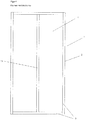
- Fig. 1 shows an element (1) according to the invention in a view from the inside, in a side view and in section.
- a rectangular frame (2) is formed from C-shaped profiles (3), the C-shaped profiles (3) with their long webs (5) forming the end faces of the frame (2) or of the element (1).
- the C-profiles (3) viewed in cross section, consist of a long web (5), two angled webs (6) and two short webs (7), as in section AA Fig. 1 and in Fig. 2 and Fig. 8 can be seen.
- C-shaped profiles (3) U-shaped profiles are also possible.
- the U-shaped profiles were similar to the C-shaped profiles (3), but the short webs (7) of the C-shaped profiles (3) are missing.
- Such C-profiles (3) or U-profiles are known and proven from so-called lightweight steel construction, are already being produced in large numbers and are therefore cheap.
- the individual C-profiles (3) are preferably connected to one another by welding, for example by spot welding, in order to form the frame (2), which can be carried out very cheaply with an industrial robot in large numbers in series production.
- other types of connection are also possible, detachable and non-detachable, as they are known from mechanical engineering or steel construction, in order to form a frame (2) from the C-profiles (3).
- the paneling (4) is then firmly attached to only one side of the frame on the finished frame (2).
- This cladding (4) can consist of, for example, an OSB board, a chipboard, a plywood board or a wood composite material.
- Fig. 2 shows that the planking (4) is preferably connected to the frame (2) by means of screws (13). Nails or rivets can also be used.
- the planking (4) can be glued to the frame (2).
- other types of connection of frame (2) and paneling (4) are also possible, as are known from mechanical engineering, steel construction or prefabricated construction. It is important that the frame (2) and cladding (4) are firmly connected so that they stiffen each other, so that the shear stresses from the cladding (4) are transferred well to the frame (2) and vice versa, so that the cladding ( 4) and frame (2) cannot move against each other.
- a connection using screws (13) is shown.
- the paneling (4) of the frame (2) is only carried out on one side in industrial prefabrication so that the inside of the C-profiles (3) remain free for assembly. After assembly on site, the connected elements (1) are then filled with thermal insulation, for example, and then planked on the second side.
- Fig. 3 shows self-drilling screws (13) which are used to connect the frame (2) to the paneling (4).
- Countersunk head screws are preferably used for this purpose.
- screws with a flat head eg hexagon head screws, are preferably used.
- Fig. 4 shows an element (1) with a central post (11).
- a center post (11) can be advantageous if the element (1) has a greater width.
- the cladding (4) can also be connected to the center post (11).
- Fig. 5 shows an element (1) which is stiffened in a framework with inclined C-profiles (12).
- Such solutions are available, for example, in the case of overlays (UE), or in the case of particularly high demands on strength.
- a further increase in strength, in particular against twisting and kinking, can be achieved if the sloping C-profiles (12) are connected to the cladding (4).
- Fig. 6 shows a ceiling element (DE) with the specific designs according to the invention.
- Fig. 7 shows an embodiment of an element (1) in an oblique view
- Fig. 8 shows an embodiment of a connection of two elements (1) in detail in a sectional drawing.
- Two elements (1) are connected to one another in such a way that the long webs (5) of the C-profiles (3), which form the end faces of the elements (1), lie against one another and are firmly connected, for example, by self-tapping screws (13).
- Moving the self-tapping screws (13) can be done very quickly and cheaply on the construction site using screw machines that are loaded with a large number of self-tapping screws (13).
- Self-drilling self-tapping screws (13) are preferably used, as they are in Fig. 3 are shown in more detail.
- connections with nails or rivets are also possible.
- the elements (1) can be assembled very quickly and cheaply on the construction site using nailing machines or bolt-firing tools or modern riveting machines.
- Fig. 9 shows schematically wedge clamps and eccentric clamps. Such connections are used when the elements (1) are planked on both sides during the industrial prefabrication and the inner sides of the sheet metal profiles (3) are no longer accessible as a result.
- the connection of the elements (1) is carried out in this case similar to the connection of the walls of prefabricated furniture.
- Fig. 10 shows an exemplary embodiment of a wall which is constructed from individual wall elements according to the invention (A1, A2, A3, B1, B2, C1, UE1, UE3, DE).
- Ceiling elements (DE) are also shown, which in this case rest on the overlays (UE1, UE3), with only the narrow face of the ceiling elements (DE) being visible in this view.
Landscapes
- Engineering & Computer Science (AREA)
- Architecture (AREA)
- Civil Engineering (AREA)
- Structural Engineering (AREA)
- Physics & Mathematics (AREA)
- Electromagnetism (AREA)
- Working Measures On Existing Buildindgs (AREA)
- Joining Of Building Structures In Genera (AREA)
Description
- Gebäude aus Fertigteilen sind vielfach bekannt. Es gibt auch Gebäude, welche aus vorgefertigten Elementen hergestellt werden, wie sie z.B. aus der
WO 2013 017 900 A1 , derDE 10 2008 048 800 A1 , derDE 198 32 410 A1 , oderDE 101 29 984 A1 bekannt sind. Alle diesen bekannten Lösungen haben den Nachteil, dass die vorgefertigten Elemente so groß und/oder so schwer sind, dass zu ihrer Montage große Kräne notwendig sind und für Ihren Transport spezielle Lastwagen. Teilweise haben die vorgefertigten Elemente die Größe einer gesamten Außenwand, oder einer halben Außenwand. Diese bekannten Lösungen haben also den Nachteil, dass sowohl der Transport, als auch die Montage der vorgefertigten Elemente teuer und umständlich ist und dass Eigenleistung beim Bauen unmöglich ist, wegen der Notwendigkeit eines Krans zur Montage. Außerdem werden diese Teile meistens speziell für ein bestimmtes geplantes Gebäude vorgefertigt, damit kann der Kostenvorteil von großen Stückzahlen nicht realisiert werden. - Aus dem Stand der Technik sind außerdem auch kleine standardisierte (oder modulare) vorgefertigte Elemente bekannt, wie z.B. aus der
EP 744 507 A1 DE 102 55 717 A1 . Zwar sind diese Elemente so leicht, dass sie von Bauarbeitern mit der Hand bewegt werden und montiert werden können und auch in Eigenleistung, z.B. mit einem Pritschenwagen, zur Baustelle transportiert werden können. Jedoch sind diese Elemente so klein, dass die Erstellung einer Wand sehr lange dauert und außerdem viele komplizierte Schritte erfordert, außerdem sind diese Elemente kompliziert aufgebaut und teuer, sodass es hier keine Vorteile zu einer modernen Ziegelmauer mehr gibt, weder bei den Kosten noch bei der Bauzeit, da moderne Hohllochziegel auch schon bis zu 50cm lang und bis zu 24 cm hoch sind. - Aus dem Stand der Technik ist außerdem noch der sogenannte Stahlleichtbau bekannt, wo beim Bauen zuerst eine Rahmenkonstruktion aus Stahlblechprofilen erstellt wird und dann das fertige Stahlskelett meistens beidseitig beplankt wird. Eine solche Bauweise ist z.B. in der Internetveröffentlichung http://www.stahl-online.de/wpcontent/uploads/2013/10/D560 Haeuser in Stahlleichtbauweise1.pdf offenbart, wobei es auch hier Überlegungen zur Vorfertigung gibt, siehe das entsprechende Kapitel, Seiten 20-22 des Artikels. Vorgefertigte Elemente nach dem Oberbegriff des Anspruchs 1 sind auch aus der
CH 550296 A - Die Erfindung hat sich zur Aufgabe gesetzt, vorgefertigte Bauelemente anzugeben, welche so groß sind und so einfach zu verbinden, dass die Erstellung einer Wand ähnlich schnell möglich ist, wie bei einem Fertigteilbau, wobei jedoch die einzelnen Elemente so leicht und handlich sind, dass sie von Hand von zwei Bauarbeitern getragen und montiert werden können, also auch in Eigenleistung, wobei die Elemente billiger sein sollen wie die bekannten Holzriegelfertigteile.
- Die Aufgabe der Erfindung wird durch die Merkmale der Ansprüche 1 und 13 gelöst. Durch die neuartige Kombination eines Rahmens aus Blechprofilen mit einer leichten Beplankung aus einem Holzwerkstoff wird ein bisher nicht realisierbares Verhältnis von niedrigem Gewicht und großer Tragfähigkeit erreicht. Damit wird es möglich, vorgefertigte Elemente zu produzieren, die so leicht und handlich sind, dass sie von Hand von zwei Bauarbeitern getragen und montiert werden können, billiger sind als bekannte Holzriegelfertigteile und so groß sind und einfach und schnell zu verbinden sind, dass damit eine Wand oder ein ganzes Gebäude in kurzer Zeit erstellt werden kann, ähnlich wie beim Fertigteilbau.
- Die Blechprofile, bzw. die aus ihnen hergestellten Rahmen sind langlebiger, also wertbeständiger als Holzriegel, leichter, wiederverwendbar oder aber auch recyclebar. Es wird also weniger Bauholz verbraucht, dessen Preise immer mehr steigen.
- Die erfindungsgemäßen Bauteile sind standardisiert und modular, also wie fixe Bausteine und nicht speziell auf das jeweilige geplante Gebäude abgestimmt wie im jetzigen Stand der Technik. Dadurch kann der Kostenvorteil von großen Stückzahlen realisiert werden, also auch der Kostenvorteil einer weitgehend automatisierten Fertigung. Auch der Kostenvorteil der Fertigung in einem Billiglohnland kann realisiert werden, weil der Kontakt zwischen Baustelle und Fertigung entfällt.
- Eine Beplankung aus OSB-Platten, Sperrholz, oder einem Holzverbundwerkstoff gemäß Anspruch 3 ist leichter und steifer, insbesondere verwindungssteifer, als eine Beplankung z.B. aus Wellblech oder gar flachem Blech, wie aus dem Stand der Technik bekannt, was für die erfindungsgemäßen Elemente wesentlich ist. Denn gemäß Aufgabe der Erfindung soll ja ein möglichst gutes Verhältnis von niedrigem Gewicht und Tragfähigkeit erreicht werden, damit die Elemente bei einem Gewicht, welches eine Montage und Transport per Hand ermöglicht, möglichst groß sein können, sodass Aufstellzeiten wie beim Fertigteilbau erreicht werden können.
- Zur Optimierung der Tragfähigkeit bei geringem Gewicht kann noch eine fachwerkliche Aussteifung der Stahlrahmen gemäß Anspruch 6 vorgesehen werden, was vor allem bei Überlagern wichtig ist. Gemäß den Merkmalen der Anspruche 2 und 7 können verschiedene Verbindungsmöglichkeiten der einzelnen Elemente bei der Montage angewendet werden. Je nach der Ausrüstung der Bauarbeiter auf der Baustelle und Anforderungen an die Festigkeit der Verbindungen der einzelnen Elemente und Anforderungen an die Schnelligkeit der Montage, können Blechschrauben, Nägel oder Nieten angewendet werden, wie sie aus dem Stahlleichtbau an sich bekannt sind. Es können alle Schrauben verwendet werden, die zur Verbindung von Blechen dieser Wandstärke geeignet sind, wie z.B. selbstbohrende Schrauben, "Blechtreiber", usw.
- Zum Verbinden zweier Elemente sind auch noch Keil- oder Exzenterverschlüsse möglich, also ähnlich jenen Verschlüssen zum schnellen Verbinden der Wände von vorgefertigten Möbelstücken. Solche Verbindungen bieten sich bei beidseitig beplankten Elementen an.
- Durch die Merkmale von Anspruch 8, den Zentriervorrichtungen, wird ein schnelles Aneinanderfügen der Elemente beim Verbinden erreicht, was die Geschwindigkeit des Bauens weiter steigert. Solche Zentriervorrichtungen können z.B. durch Einprägungen in die Blechprofile hergestellt werden.
- Gemäß Anspruch 11 könne die C-Profile oder U-Profile aus verzinktem Stahlblech, korrosionsgeschütztem Stahlblech, Aluminiumblech oder Nirosta-Blechen hergestellt werden, je nach Anforderungen an Korrosionsbeständigkeit, Preis und Verhältnis von Gewicht zu Tragfähigkeit.
- Durch die Merkmale von Anspruch 12, der Herstellung von vereinfachten erfindungsgemäßen Elementen im Modellmaßstab, ergibt sich der große Vorteil, dass zu Planungszwecken und Präsentationszwecken mit wenig Aufwand ein Modell eines Bauwerks in kleinem Maßstab erstellt werden kann und solche Modelle auch leicht abgewandelt und geändert werden können.
- Durch die standardisierten Elemente sind auch einfache Planungen am PC selbst durch Laien möglich, z.B. mittels zur Verfügung gestellter Komponenten in einem Freeware 3D-Programm.
- Außerdem hat jedes standardisierte Element immer gleichbleibende statische Werte. Dadurch wird die Berechnung der Statik sehr vereinfacht und kann mit einem auf die Elemente abgestimmten Programm sehr leicht und billig durchgeführt werden.
- Durch die Merkmale der Ansprüche 14 und 15 können Bauwerke schnell umgebaut, verändert oder zurückgebaut werden, wobei ausgebaute Elemente ohne Wertverlust wiederverwendet werden können und auch unbegrenzt lange gelagert werden können.
- Weitere Vorteile ergeben sich aus der folgenden Beschreibung und den Zeichnungen Beschreibung mit Hilfe der Zeichnungen
-
Fig.1 Element in Ansicht, Seitenansicht und Schnitt -
Fig.2 Verbindung Rahmen mit Beplankung im Schnitt -
Fig.3 Blechschrauben -
Fig.4 Element mit Mittelsteher -
Fig.5 Element fachwerklich ausgesteift -
Fig.6 Deckenelement -
Fig.7 Element im Schrägriss -
Fig.8 Detail Verbindung von Elementen -
Fig.9 Keilspanner und Exzenterspanner -
Fig.10 Wand aus einzelnen Elementen -
Fig. 1 zeigt ein erfindungsgemäßes Element(1) in einer Ansicht von innen, in einer Seitenansicht und im Schnitt. Aus C-förmigen Profilen (3) wird ein rechteckiger Rahmen(2) geformt, wobei die C-förmigen Profile(3) mit ihren langen Stegen(5) die Stirnseiten des Rahmens(2) bzw. des Elements(1) bilden. Die C-Profile(3) bestehen im Querschnitt betrachtet aus einem langen Steg(5), zwei Winkelstegen(6) und zwei kurzen Stegen(7), wie im Schnitt A-A derFig. 1 und inFig. 2 undFig. 8 ersichtlich ist. Anstatt C-förmigen Profilen (3) sind auch U-förmige Profile möglich. Die U-förmigen Profile glichen den C-förmigen Profilen (3), jedoch fehlen die kurzen Stege(7) der C-förmigen Profile(3). Solche C-Profile (3) bzw. U-Profile sind aus dem sogenannten Stahlleichtbau bekannt und bewährt, werden jetzt schon in großer Stückzahl hergestellt und sind daher billig. Die einzelnen C-Profile(3) werden untereinander vorzugsweise durch Schweißen, z.B. durch Punktschweißen, verbunden, um den Rahmen(2) zu formen, was bei Serienfertigung in großer Stückzahl mit einem Industrieroboter sehr billig durchgeführt werden kann. Es sind aber auch andere Verbindungsarten möglich, lösbare und unlösbare, wie sie aus dem Maschinenbau oder Stahlbau bekannt sind, um aus den C-Profilen(3) einen Rahmen(2) zu formen. An dem fertigen Rahmen(2) wird dann die Beplankung(4) auf nur eine Seite des Rahmens fest angebracht. Diese Beplankung(4) kann aus z.B. einer OSB-Platte, einer Spanplatte, einer Sperrholzplatte oder einem Holzverbundwerkstoff bestehen. Wichtig ist, dass durch das Zusammenwirken von Rahmen(2) und Beplankung(4) die Steifigkeit bzw. Festigkeit gegen Verwindung und Knickung stark erhöht wird. Dadurch wird ein bisher nicht realisierbares Verhältnis von niedrigem Gewicht und großer Tragfähigkeit erreicht. Dadurch können die Elemente(1) so leicht sein, dass sie von Hand bewegt und montiert werden können und trotzdem so groß, dass eine Montagegeschwindigkeit ähnlich einem Fertigteilbau erreicht wird. -
Fig. 2 zeigt, dass die Beplankung(4) vorzugsweise mittels Schrauben(13) mit dem Rahmen(2) verbunden wird. Es können auch Nägel oder Nieten verwendet werden. Zusätzlich kann die Beplankung(4) noch mit dem Rahmen(2) verklebt werden. Es sind aber auch andere Verbindungsarten von Rahmen(2) und Beplankung(4) möglich, wie sie aus dem Maschinenbau, Stahlbau oder Fertigteilbau bekannt sind. Wichtig, dass Rahmen(2) und Beplankung(4) so fest verbunden sind, dass sie sich gegenseitig aussteifen, dass also die Schubspannungen von der Beplankung(4) gut auf den Rahmen(2) übertragen werden und umgekehrt, dass sich also Beplankung(4) und Rahmen(2) nicht gegeneinander verschieben können. InFig. 2 wird eine Verbindung mittels Schrauben(13) dargestellt. Erfindungsgemäß wird die Beplankung(4) des Rahmens(2) nur auf einer Seite in der industriellen Vorfertigung durchgeführt, damit die Innenseiten der C-Profile(3) für die Montage frei bleiben. Nach dem Zusammenfügen auf der Baustelle können die verbundenen Elemente(1) dann z.B. mit Wärmedämmung gefüllt werden und dann auf der zweiten Seite beplankt werden. -
Fig. 3 zeigt selbstbohrende Schrauben(13), welche verwendet werden, um den Rahmen(2) mit der Beplankung(4) zu verbinden. Dazu werden vorzugsweise Senkkopfschrauben verwendet. Für die Verbindung von zwei Elementen(1) werden vorzugsweise Schrauben mit flachem Kopf, z.B. Sechskantschrauben verwendet. -
Fig. 4 zeigt ein Element(1) mit einem Mittelsteher(11). Ein solcher Mittelsteher(11) kann vorteilhaft sein, wenn das Element(1) eine größere Breite erreicht. Selbstverständlich kann die Beplankung(4) auch mit dem Mittelsteher(11) verbunden werden. -
Fig. 5 zeigt ein Element(1), welches mit schräg verlaufenden C-Profilen(12) fachwerklich ausgesteift ist. Solche Lösungen bieten sich z.B. bei Überlagern(UE) an, oder bei besonders großen Anforderungen an die Festigkeit. Eine weitere Steigerung der Festigkeit, insbesondere gegen Verwindung und Knickung kann erreicht werden, wenn die schräg verlaufenden C-Profile(12) mit der Beplankung(4) verbunden sind. -
Fig. 6 zeigt ein Deckenelement(DE) mit den spezifischen erfindungsgemäßen Ausführungen. -
Fig. 7 zeigt ein Ausführungsbeispiel eines Elements(1) im Schrägriss -
Fig. 8 zeigt ein Ausführungsbeispiel einer Verbindung von zwei Elementen(1) im Detail in einer Schnittzeichnung. Zwei Elemente(1) werden miteinander so verbunden, dass die langen Stege(5) der C-Profile(3), welche die Stirnseiten der Elemente(1) bilden, aneinander anliegen und z.B. durch Blechschrauben(13) fest verbunden werden. Das Versetzen der Blechschrauben(13) kann mit Schraubmaschinen, welche mit einer großen Anzahl von Blechschrauben(13) geladen sind, auf der Baustelle sehr schnell und billig erfolgen. Vorzugsweise werden selbstbohrende Blechschrauben(13) verwendet, wie sie inFig. 3 genauer dargestellt sind. - Anstatt einer Verbindung mittels Blechschrauben(13) sind auch Verbindungen mit Nägeln oder Nieten möglich. Mit Nagelmaschinen bzw. Bolzensetzgeräten oder modernen Nietmaschinen kann die Montage der Elemente(1) auf der Baustelle sehr schnell und billig erfolgen.
-
Fig. 9 zeigt schematisch Keilspanner und Exzenterspanner. Solche Verbindungen kommen dann zum Einsatz, wenn die Elemente(1) schon bei der industriellen Vorfertigung beidseitig beplankt sind und die Innenseiten der Blechprofile(3) dadurch nicht mehr zugänglich sind. Die Verbindung der Elemente(1) erfolgt in diesem Fall ähnlich wie das Verbinden der Wände von vorgefertigten Möbelstücken. -
Fig. 10 zeigt ein Ausführungsbeispiel einer Wand, welche aus einzelnen erfindungsgemäßen Wandelementen(Al, A2, A3, B1, B2, C1, UE1, UE3, DE) aufgebaut ist. Es sind auch Deckenelemente(DE) dargestellt, welche in diesem Fall auf den Überlagern(UE1, UE3) aufliegen, wobei in dieser Ansicht nur die schmale Stirnseite der Deckenelemente(DE) sichtbar ist.
Claims (15)
- Industriell vorgefertigte Elemente (1) zum Errichten eines Bauwerks, welche aus einem rechteckigen Rahmen(2) aus Blechprofilen(3) und einer flachen Beplankung(4) bestehen, wobei der Rahmen(2) aus C-förmigen oder U-förmigen Blechprofilen(3) und die Beplankung(4) aus einem Holzwerkstoff besteht, wobei die langen Stege(5) der Blechprofile(3) die äußeren Ränder, also die Stirnseiten, der Elemente(1) bilden, und wobei die Größe der einzelnen Elemente (1) so gewählt wird, dass sie von zwei Mann getragen und aneinandergefügt werden können und wobei mehrere Elemente (1) auf einer Palette gestapelt werden können, dadurch gekennzeichnet, dass die Beplankung (4) in der Vorfertigung nur auf einer Seite aufgebracht wird, wobei die Elemente (1) standardisiert und modular ausgeführt sind, wobei nur eine begrenzte Anzahl an verschiedenen Elementen(1) erstellt wird, wobei es drei verschiedene Grundtypen von Elementen gibt, nämlich Wandelemente(A1,A2,A3, usw.), Deckenelemente(DE) und Überlager(UE1,UE2,UE3, usw.), wobei die Überlager(UE1,UE2,UE3, usw.) die Wände nach oben abschließen, also zwischen Deckenelementen (DE) und Wandelementen (A1, A2, A3, usw.) Überlager eingebaut sind, wobei die Wandelemente (A1,A2,A3, usw.) eine Grundgröße aufweisen und es dazu Ausgleichselemente (B1,B2,C1,C2, usw.) verschiedener Größen gibt, um unterschiedliche Wandöffnungen für Fenster, Türen, oder Ähnliches, leicht realisieren zu können.
- Elemente(1) nach Anspruch 1, dadurch gekennzeichnet, dass zwei Elemente(1) miteinander so verbunden werden, dass die langen Stege(5) der C-Profile(3) oder U-Profile, welche die Stirnseiten der Elemente(1) bilden, aneinander anliegen und durch Blechschrauben(13), Nägel, Nieten, Exzenterverschlüsse oder Keilverschlüsse fest verbunden werden.
- Elemente(1) nach Anspruch 1 oder 2, dadurch gekennzeichnet, dass die Beplankung(4) aus einer OSB-Platte, einer Spanplatte, einer Sperrholzplatte, oder einem Holzverbundwerkstoff besteht.
- Elemente(1) nach einem der Ansprüche 1-3, dadurch gekennzeichnet, dass die Beplankung(4) mit dem Rahmen(2) mittels Blechschrauben(13), Nägeln, oder Nieten und/oder durch Kleben verbunden ist.
- Elemente(1) nach einem der Ansprüche 1-3, dadurch gekennzeichnet, dass die Rahmen(2) der einzelnen Elemente(1) bei größerer Breite zusätzlich Mittelsteher(11) aus einem C-Profil(3) oder U-Profil haben.
- Elemente(1) nach einem der Ansprüche 1-3, dadurch gekennzeichnet, dass die Rahmen(2) der einzelnen Elemente(1) durch zusätzliche schräg verlaufende Profile(12) fachwerklich ausgesteift sind.
- Elemente (1)nach Anspruch 1 oder 2, dadurch gekennzeichnet, dass die Verbindung zwischen zwei Elementen(1) eine lösbare Verbindung ist.
- Elemente(1) nach Anspruch 1 oder 2, dadurch gekennzeichnet, dass die Blechprofile(3) zum leichteren Ausrichten zweier zu verbindender Elemente(1) Zentriervorrichtungen aufweisen.
- Elemente(1) nach einem der Ansprüche 1-3, dadurch gekennzeichnet, dass die Wandelemente(A1,A2,A3, usw.) eine Höhe von ca. 240cm haben und mehrere mögliche Breiten von ca. 20cm, 31cm, 41cm, 62cm und 125cm und die Überlager(UE) eine Höhe von ca. 38cm und mehrere mögliche Breiten von ca. 31cm, 41cm, 62cm, 125cm, 178cm, 250cm und 312cm und die Ausgleichselemente(B1,B2,usw.) eine Höhe von ca. 100 cm und Ausgleichselemente(C1,C2, usw.) eine Höhe von ca.60cm haben.
- Elemente(1) nach einem der Ansprüche 1-3, dadurch gekennzeichnet, dass die C-Profile(3) oder U-Profile(3), je nach statischen Anforderungen, im Querschnitt eine Höhe von 80-200mm, eine Breite von 45-60mm und eine Wandstärke von 1-2mm haben.
- Elemente (1)nach einem der Ansprüche 1-3, dadurch gekennzeichnet, dass die C-Profile(3) oder U-Profile(3) aus verzinktem Stahlblech, korrosionsgeschütztem Stahlblech, Aluminiumblech oder Nirosta-Blechen hergestellt werden.
- Elemente(1) nach Anspruch 1, dadurch gekennzeichnet, dass die Elemente(1) im verkleinerten Maßstab, bzw. Modellmaßstab, mit vereinfachten Verbindungen der Elemente(1), hergestellt sind, so dass zu Planungszwecken und Präsentationszwecken mit wenig Aufwand ein Modell eines Bauwerks erstellt werden kann.
- Verfahren zum Errichten eines Bauwerks aus vorgefertigten Elementen (1) nach einem der Ansprüche 1-11, dadurch gekennzeichnet, dass das Verfahren aus zwei Teilen besteht, wobei Teil 1 die industrielle Vorfertigung der Elemente (1) betrifft und Teil 2 das Zusammenfügen der Elemente(1) auf der Baustelle, wobei in Teil 1 nur eine begrenzte Anzahl verschiedener Elemente(1) erstellt wird, welche standardisiert sind und modular zueinander, um eine industrielle Massenfertigung zu ermöglichen, wobei Teil 1 des Verfahrens folgende Schritte enthält:1a, Formen eines rechteckigen Rahmens (2) aus C-förmigen oder U-förmigen Profilen (3)1b, Verbinden der einzelnen Profile (3) des Rahmens (2) vorzugsweise durch Schweißen, vorzugsweisen durch Punktschweißen, vorzugsweise mittels Industrieroboter1c, Anbringen der Beplankung (4) auf nur einer Seite des Rahmensund Teil 2 des Verfahrens folgende Schritte enthält:2a, Aneinanderfügen der Elemente (1) und festes Verbinden dieser Elemente (1), vorzugsweise mittels Schrauben (13)2b, Füllen der fertig montierten Elemente (1) mit Wärmedämmung2c, Anbringen der Beplankung (4) auf der zweiten Seite des Rahmens (2)
- Bauwerk aus vorgefertigten Elementen(1) nach einem der Ansprüche 1-11, dadurch gekennzeichnet, dass die Verbindung(13) einzelner Elemente(1) lösbar ausgeführt wird, so dass ein bestehendes Bauwerk leicht erweitert, zurückgebaut oder demontiert werden kann.
- Bauwerk aus vorgefertigten Elementen(1) nach einem der Ansprüche 1-11, dadurch gekennzeichnet, dass die innere oder äußere Beplankung(4) der Elemente(1) und die Verbindungen(13) der Elemente(1) so entfernbar sind, dass die Elemente(1) selbst nicht zerstört werden, also beispielsweise Blechschrauben(13) lösen, oder Nieten oder Nägel aufbohren, so dass die Elemente(1) nach dem Abbau gelagert und ohne Wertverlust wiederverwendet werden können.
Applications Claiming Priority (2)
| Application Number | Priority Date | Filing Date | Title |
|---|---|---|---|
| ATA505/2015A AT517545B1 (de) | 2015-07-29 | 2015-07-29 | Vorgefertigte Elemente aus beplankten Stahlrahmen zum Bau eines Gebäudes |
| PCT/AT2016/000075 WO2017015680A1 (de) | 2015-07-29 | 2016-07-11 | Vorgefertigte elemente aus beplankten stahlrahmen zum bau eines gebäudes |
Publications (2)
| Publication Number | Publication Date |
|---|---|
| EP3329063A1 EP3329063A1 (de) | 2018-06-06 |
| EP3329063B1 true EP3329063B1 (de) | 2021-08-04 |
Family
ID=56567309
Family Applications (1)
| Application Number | Title | Priority Date | Filing Date |
|---|---|---|---|
| EP16747430.3A Active EP3329063B1 (de) | 2015-07-29 | 2016-07-11 | Vorgefertigte elemente aus beplankten stahlrahmen zum bau eines gebäudes |
Country Status (3)
| Country | Link |
|---|---|
| EP (1) | EP3329063B1 (de) |
| AT (1) | AT517545B1 (de) |
| WO (1) | WO2017015680A1 (de) |
Families Citing this family (1)
| Publication number | Priority date | Publication date | Assignee | Title |
|---|---|---|---|---|
| IT201700060534A1 (it) * | 2017-06-01 | 2018-12-01 | Adige Spa | Elemento costruttivo piano, in particolare per la realizzazione di strutture di orizzontamento. |
Citations (1)
| Publication number | Priority date | Publication date | Assignee | Title |
|---|---|---|---|---|
| DE102014000839A1 (de) * | 2013-11-04 | 2015-05-07 | Sträter-Modularesysteme GmbH | Messe-Fertigbausystem mit Fertig-Rahmenmodulen |
Family Cites Families (12)
| Publication number | Priority date | Publication date | Assignee | Title |
|---|---|---|---|---|
| GB853216A (en) * | 1958-04-22 | 1960-11-02 | Leonard Joseph Blumenthal | Improved wall partitioning |
| CH550296A (de) * | 1972-06-13 | 1974-06-14 | Schoenenberger Helmut | Elementbau. |
| DE7419959U (de) * | 1974-06-10 | 1983-02-17 | Furnier- Und Sperrholzwerk J.F. Werz Jr. Kg Werzalit-Pressholzwerk, 7141 Oberstenfeld | Aus austauschbaren elementen zusammensetz- und abaenderbarer trennwand - aufbau- |
| DE2448946A1 (de) * | 1974-10-15 | 1976-04-29 | Hunlas Bv | Profilsystem zur errichtung von waenden oder dergleichen |
| FR2560254B2 (fr) * | 1983-09-20 | 1989-01-06 | Degut Andre | Dispositif de construction au moyen d'elements prefabriques |
| US4914883A (en) * | 1986-10-22 | 1990-04-10 | Foamseal, Inc. | Method of bonding structural support channels to a panel |
| US5060432A (en) * | 1990-12-07 | 1991-10-29 | Christian William D | Modular panel |
| DE4329413A1 (de) * | 1993-09-01 | 1995-03-02 | Zorbedo Sa | Holz-Montage-Bausystem aus ganztragenden und raumschließenden Raster-Holz-Bauelementen |
| AP1073A (en) * | 1997-05-08 | 2002-06-05 | Nabil Nasri Gazal | Modular sandwich panel and method for housing construction. |
| US8307608B2 (en) * | 2006-05-18 | 2012-11-13 | Harig Christopher W | Modular panel wall assemblies |
| US8769908B1 (en) * | 2011-08-31 | 2014-07-08 | Patrick J. Santini | Modular building panel |
| ITTO20130918A1 (it) * | 2013-11-13 | 2015-05-14 | Enrico Aime | Pannello modulare prefabbricato per costruzioni, in particolare per abitazioni. |
-
2015
- 2015-07-29 AT ATA505/2015A patent/AT517545B1/de not_active IP Right Cessation
-
2016
- 2016-07-11 EP EP16747430.3A patent/EP3329063B1/de active Active
- 2016-07-11 WO PCT/AT2016/000075 patent/WO2017015680A1/de not_active Ceased
Patent Citations (1)
| Publication number | Priority date | Publication date | Assignee | Title |
|---|---|---|---|---|
| DE102014000839A1 (de) * | 2013-11-04 | 2015-05-07 | Sträter-Modularesysteme GmbH | Messe-Fertigbausystem mit Fertig-Rahmenmodulen |
Also Published As
| Publication number | Publication date |
|---|---|
| AT517545B1 (de) | 2017-05-15 |
| EP3329063A1 (de) | 2018-06-06 |
| AT517545A1 (de) | 2017-02-15 |
| WO2017015680A1 (de) | 2017-02-02 |
Similar Documents
| Publication | Publication Date | Title |
|---|---|---|
| DE1709403C3 (de) | Raumkasten in Skelettbauweise | |
| DE2128609A1 (de) | Verstärkte Schalungsplatte fur Be tonschalungen | |
| DE3203684A1 (de) | Blockhaus | |
| EP2099978A1 (de) | Bausystem für hochbauten | |
| DE202014103897U1 (de) | Rohrverbinder | |
| DE3780064T2 (de) | Wand. | |
| DE3903770A1 (de) | Verbindungs-stuetze zur erstellung von containergehaeusen bzw. fertigbau-raumkoerpern | |
| EP3247842A1 (de) | Schalungsträger und schalungskonstruktion | |
| EP3329063B1 (de) | Vorgefertigte elemente aus beplankten stahlrahmen zum bau eines gebäudes | |
| EP3049591A1 (de) | Gerüstriegel | |
| WO2017046365A1 (de) | Flächiges bauelement, aussteifende scheibe, gebäudemodul, treppenhausmodul und mehrstöckiges gebäude | |
| DE10016660A1 (de) | Wandelement | |
| EP0953088B9 (de) | Tragwerk und dessen konstruktionselemente | |
| DE3237467C1 (de) | Traggeruest zum Einruesten von Bauwerken | |
| EP3363961A1 (de) | Geschossdeckenkonstruktion und gebäude aus holz | |
| DE2051246A1 (de) | Außenwand | |
| DE2310312A1 (de) | Gebaeude, hergestellt unter verwendung vorfabrizierter, grossformatiger bauelemente | |
| EP2415681B1 (de) | Lager- und Transportvorrichtung | |
| DE60315714T2 (de) | Modularbauelement und verfahren zu seiner montage | |
| DE824255C (de) | Verfahren zur Errichtung von Gebaeuden in unvollstaendiger Skelettbauweise | |
| DE8510083U1 (de) | Bauelementesatz für ein Bauwerk | |
| DE2263027A1 (de) | Aus kurzen holzteilen zusammengesetztes bauteil | |
| DE805786C (de) | Bauteil, Verfahren zu dessen Herstellung, Vorrichtung zur Durchfuehrung dieses Verfahrens und Verfahren zum Herstellen von Bauwerken | |
| DE804954C (de) | Fachwerknetz als tragender Teil einer Wand | |
| CH697250B1 (de) | Hohlwand-Bewehrungskorb. |
Legal Events
| Date | Code | Title | Description |
|---|---|---|---|
| STAA | Information on the status of an ep patent application or granted ep patent |
Free format text: STATUS: THE INTERNATIONAL PUBLICATION HAS BEEN MADE |
|
| PUAI | Public reference made under article 153(3) epc to a published international application that has entered the european phase |
Free format text: ORIGINAL CODE: 0009012 |
|
| STAA | Information on the status of an ep patent application or granted ep patent |
Free format text: STATUS: REQUEST FOR EXAMINATION WAS MADE |
|
| 17P | Request for examination filed |
Effective date: 20171212 |
|
| AK | Designated contracting states |
Kind code of ref document: A1 Designated state(s): AL AT BE BG CH CY CZ DE DK EE ES FI FR GB GR HR HU IE IS IT LI LT LU LV MC MK MT NL NO PL PT RO RS SE SI SK SM TR |
|
| AX | Request for extension of the european patent |
Extension state: BA ME |
|
| DAV | Request for validation of the european patent (deleted) | ||
| DAX | Request for extension of the european patent (deleted) | ||
| STAA | Information on the status of an ep patent application or granted ep patent |
Free format text: STATUS: EXAMINATION IS IN PROGRESS |
|
| 17Q | First examination report despatched |
Effective date: 20190607 |
|
| GRAP | Despatch of communication of intention to grant a patent |
Free format text: ORIGINAL CODE: EPIDOSNIGR1 |
|
| STAA | Information on the status of an ep patent application or granted ep patent |
Free format text: STATUS: GRANT OF PATENT IS INTENDED |
|
| INTG | Intention to grant announced |
Effective date: 20210512 |
|
| GRAS | Grant fee paid |
Free format text: ORIGINAL CODE: EPIDOSNIGR3 |
|
| GRAA | (expected) grant |
Free format text: ORIGINAL CODE: 0009210 |
|
| STAA | Information on the status of an ep patent application or granted ep patent |
Free format text: STATUS: THE PATENT HAS BEEN GRANTED |
|
| AK | Designated contracting states |
Kind code of ref document: B1 Designated state(s): AL AT BE BG CH CY CZ DE DK EE ES FI FR GB GR HR HU IE IS IT LI LT LU LV MC MK MT NL NO PL PT RO RS SE SI SK SM TR |
|
| REG | Reference to a national code |
Ref country code: GB Ref legal event code: FG4D Free format text: NOT ENGLISH |
|
| REG | Reference to a national code |
Ref country code: AT Ref legal event code: REF Ref document number: 1417133 Country of ref document: AT Kind code of ref document: T Effective date: 20210815 |
|
| REG | Reference to a national code |
Ref country code: CH Ref legal event code: EP |
|
| REG | Reference to a national code |
Ref country code: DE Ref legal event code: R096 Ref document number: 502016013553 Country of ref document: DE |
|
| REG | Reference to a national code |
Ref country code: IE Ref legal event code: FG4D Free format text: LANGUAGE OF EP DOCUMENT: GERMAN |
|
| REG | Reference to a national code |
Ref country code: LT Ref legal event code: MG9D |
|
| REG | Reference to a national code |
Ref country code: NL Ref legal event code: MP Effective date: 20210804 |
|
| PG25 | Lapsed in a contracting state [announced via postgrant information from national office to epo] |
Ref country code: RS Free format text: LAPSE BECAUSE OF FAILURE TO SUBMIT A TRANSLATION OF THE DESCRIPTION OR TO PAY THE FEE WITHIN THE PRESCRIBED TIME-LIMIT Effective date: 20210804 Ref country code: SE Free format text: LAPSE BECAUSE OF FAILURE TO SUBMIT A TRANSLATION OF THE DESCRIPTION OR TO PAY THE FEE WITHIN THE PRESCRIBED TIME-LIMIT Effective date: 20210804 Ref country code: LT Free format text: LAPSE BECAUSE OF FAILURE TO SUBMIT A TRANSLATION OF THE DESCRIPTION OR TO PAY THE FEE WITHIN THE PRESCRIBED TIME-LIMIT Effective date: 20210804 Ref country code: BG Free format text: LAPSE BECAUSE OF FAILURE TO SUBMIT A TRANSLATION OF THE DESCRIPTION OR TO PAY THE FEE WITHIN THE PRESCRIBED TIME-LIMIT Effective date: 20211104 Ref country code: NO Free format text: LAPSE BECAUSE OF FAILURE TO SUBMIT A TRANSLATION OF THE DESCRIPTION OR TO PAY THE FEE WITHIN THE PRESCRIBED TIME-LIMIT Effective date: 20211104 Ref country code: PT Free format text: LAPSE BECAUSE OF FAILURE TO SUBMIT A TRANSLATION OF THE DESCRIPTION OR TO PAY THE FEE WITHIN THE PRESCRIBED TIME-LIMIT Effective date: 20211206 Ref country code: ES Free format text: LAPSE BECAUSE OF FAILURE TO SUBMIT A TRANSLATION OF THE DESCRIPTION OR TO PAY THE FEE WITHIN THE PRESCRIBED TIME-LIMIT Effective date: 20210804 Ref country code: FI Free format text: LAPSE BECAUSE OF FAILURE TO SUBMIT A TRANSLATION OF THE DESCRIPTION OR TO PAY THE FEE WITHIN THE PRESCRIBED TIME-LIMIT Effective date: 20210804 Ref country code: HR Free format text: LAPSE BECAUSE OF FAILURE TO SUBMIT A TRANSLATION OF THE DESCRIPTION OR TO PAY THE FEE WITHIN THE PRESCRIBED TIME-LIMIT Effective date: 20210804 |
|
| PG25 | Lapsed in a contracting state [announced via postgrant information from national office to epo] |
Ref country code: PL Free format text: LAPSE BECAUSE OF FAILURE TO SUBMIT A TRANSLATION OF THE DESCRIPTION OR TO PAY THE FEE WITHIN THE PRESCRIBED TIME-LIMIT Effective date: 20210804 Ref country code: LV Free format text: LAPSE BECAUSE OF FAILURE TO SUBMIT A TRANSLATION OF THE DESCRIPTION OR TO PAY THE FEE WITHIN THE PRESCRIBED TIME-LIMIT Effective date: 20210804 Ref country code: GR Free format text: LAPSE BECAUSE OF FAILURE TO SUBMIT A TRANSLATION OF THE DESCRIPTION OR TO PAY THE FEE WITHIN THE PRESCRIBED TIME-LIMIT Effective date: 20211105 |
|
| PG25 | Lapsed in a contracting state [announced via postgrant information from national office to epo] |
Ref country code: NL Free format text: LAPSE BECAUSE OF FAILURE TO SUBMIT A TRANSLATION OF THE DESCRIPTION OR TO PAY THE FEE WITHIN THE PRESCRIBED TIME-LIMIT Effective date: 20210804 |
|
| PG25 | Lapsed in a contracting state [announced via postgrant information from national office to epo] |
Ref country code: DK Free format text: LAPSE BECAUSE OF FAILURE TO SUBMIT A TRANSLATION OF THE DESCRIPTION OR TO PAY THE FEE WITHIN THE PRESCRIBED TIME-LIMIT Effective date: 20210804 |
|
| REG | Reference to a national code |
Ref country code: DE Ref legal event code: R097 Ref document number: 502016013553 Country of ref document: DE |
|
| PG25 | Lapsed in a contracting state [announced via postgrant information from national office to epo] |
Ref country code: SM Free format text: LAPSE BECAUSE OF FAILURE TO SUBMIT A TRANSLATION OF THE DESCRIPTION OR TO PAY THE FEE WITHIN THE PRESCRIBED TIME-LIMIT Effective date: 20210804 Ref country code: SK Free format text: LAPSE BECAUSE OF FAILURE TO SUBMIT A TRANSLATION OF THE DESCRIPTION OR TO PAY THE FEE WITHIN THE PRESCRIBED TIME-LIMIT Effective date: 20210804 Ref country code: RO Free format text: LAPSE BECAUSE OF FAILURE TO SUBMIT A TRANSLATION OF THE DESCRIPTION OR TO PAY THE FEE WITHIN THE PRESCRIBED TIME-LIMIT Effective date: 20210804 Ref country code: EE Free format text: LAPSE BECAUSE OF FAILURE TO SUBMIT A TRANSLATION OF THE DESCRIPTION OR TO PAY THE FEE WITHIN THE PRESCRIBED TIME-LIMIT Effective date: 20210804 Ref country code: CZ Free format text: LAPSE BECAUSE OF FAILURE TO SUBMIT A TRANSLATION OF THE DESCRIPTION OR TO PAY THE FEE WITHIN THE PRESCRIBED TIME-LIMIT Effective date: 20210804 Ref country code: AL Free format text: LAPSE BECAUSE OF FAILURE TO SUBMIT A TRANSLATION OF THE DESCRIPTION OR TO PAY THE FEE WITHIN THE PRESCRIBED TIME-LIMIT Effective date: 20210804 |
|
| PLBE | No opposition filed within time limit |
Free format text: ORIGINAL CODE: 0009261 |
|
| STAA | Information on the status of an ep patent application or granted ep patent |
Free format text: STATUS: NO OPPOSITION FILED WITHIN TIME LIMIT |
|
| 26N | No opposition filed |
Effective date: 20220506 |
|
| PG25 | Lapsed in a contracting state [announced via postgrant information from national office to epo] |
Ref country code: IT Free format text: LAPSE BECAUSE OF FAILURE TO SUBMIT A TRANSLATION OF THE DESCRIPTION OR TO PAY THE FEE WITHIN THE PRESCRIBED TIME-LIMIT Effective date: 20210804 |
|
| PG25 | Lapsed in a contracting state [announced via postgrant information from national office to epo] |
Ref country code: SI Free format text: LAPSE BECAUSE OF FAILURE TO SUBMIT A TRANSLATION OF THE DESCRIPTION OR TO PAY THE FEE WITHIN THE PRESCRIBED TIME-LIMIT Effective date: 20210804 |
|
| PG25 | Lapsed in a contracting state [announced via postgrant information from national office to epo] |
Ref country code: MC Free format text: LAPSE BECAUSE OF FAILURE TO SUBMIT A TRANSLATION OF THE DESCRIPTION OR TO PAY THE FEE WITHIN THE PRESCRIBED TIME-LIMIT Effective date: 20210804 |
|
| REG | Reference to a national code |
Ref country code: CH Ref legal event code: PL |
|
| GBPC | Gb: european patent ceased through non-payment of renewal fee |
Effective date: 20220711 |
|
| REG | Reference to a national code |
Ref country code: BE Ref legal event code: MM Effective date: 20220731 |
|
| PG25 | Lapsed in a contracting state [announced via postgrant information from national office to epo] |
Ref country code: LU Free format text: LAPSE BECAUSE OF NON-PAYMENT OF DUE FEES Effective date: 20220711 Ref country code: LI Free format text: LAPSE BECAUSE OF NON-PAYMENT OF DUE FEES Effective date: 20220731 Ref country code: FR Free format text: LAPSE BECAUSE OF NON-PAYMENT OF DUE FEES Effective date: 20220731 Ref country code: CH Free format text: LAPSE BECAUSE OF NON-PAYMENT OF DUE FEES Effective date: 20220731 |
|
| PG25 | Lapsed in a contracting state [announced via postgrant information from national office to epo] |
Ref country code: GB Free format text: LAPSE BECAUSE OF NON-PAYMENT OF DUE FEES Effective date: 20220711 Ref country code: BE Free format text: LAPSE BECAUSE OF NON-PAYMENT OF DUE FEES Effective date: 20220731 |
|
| PG25 | Lapsed in a contracting state [announced via postgrant information from national office to epo] |
Ref country code: IE Free format text: LAPSE BECAUSE OF NON-PAYMENT OF DUE FEES Effective date: 20220711 |
|
| PGFP | Annual fee paid to national office [announced via postgrant information from national office to epo] |
Ref country code: AT Payment date: 20230712 Year of fee payment: 8 |
|
| PGFP | Annual fee paid to national office [announced via postgrant information from national office to epo] |
Ref country code: DE Payment date: 20230712 Year of fee payment: 8 |
|
| PG25 | Lapsed in a contracting state [announced via postgrant information from national office to epo] |
Ref country code: HU Free format text: LAPSE BECAUSE OF FAILURE TO SUBMIT A TRANSLATION OF THE DESCRIPTION OR TO PAY THE FEE WITHIN THE PRESCRIBED TIME-LIMIT; INVALID AB INITIO Effective date: 20160711 |
|
| PG25 | Lapsed in a contracting state [announced via postgrant information from national office to epo] |
Ref country code: MK Free format text: LAPSE BECAUSE OF FAILURE TO SUBMIT A TRANSLATION OF THE DESCRIPTION OR TO PAY THE FEE WITHIN THE PRESCRIBED TIME-LIMIT Effective date: 20210804 Ref country code: CY Free format text: LAPSE BECAUSE OF FAILURE TO SUBMIT A TRANSLATION OF THE DESCRIPTION OR TO PAY THE FEE WITHIN THE PRESCRIBED TIME-LIMIT Effective date: 20210804 |
|
| PG25 | Lapsed in a contracting state [announced via postgrant information from national office to epo] |
Ref country code: MT Free format text: LAPSE BECAUSE OF FAILURE TO SUBMIT A TRANSLATION OF THE DESCRIPTION OR TO PAY THE FEE WITHIN THE PRESCRIBED TIME-LIMIT Effective date: 20210804 |
|
| REG | Reference to a national code |
Ref country code: DE Ref legal event code: R119 Ref document number: 502016013553 Country of ref document: DE |
|
| REG | Reference to a national code |
Ref country code: AT Ref legal event code: MM01 Ref document number: 1417133 Country of ref document: AT Kind code of ref document: T Effective date: 20240711 |
|
| PG25 | Lapsed in a contracting state [announced via postgrant information from national office to epo] |
Ref country code: DE Free format text: LAPSE BECAUSE OF NON-PAYMENT OF DUE FEES Effective date: 20250201 |
|
| PG25 | Lapsed in a contracting state [announced via postgrant information from national office to epo] |
Ref country code: AT Free format text: LAPSE BECAUSE OF NON-PAYMENT OF DUE FEES Effective date: 20240711 |
|
| PG25 | Lapsed in a contracting state [announced via postgrant information from national office to epo] |
Ref country code: TR Free format text: LAPSE BECAUSE OF FAILURE TO SUBMIT A TRANSLATION OF THE DESCRIPTION OR TO PAY THE FEE WITHIN THE PRESCRIBED TIME-LIMIT Effective date: 20210804 |