EP3328600B1 - Werkzeugmaschinentrennvorrichtung - Google Patents
Werkzeugmaschinentrennvorrichtung Download PDFInfo
- Publication number
- EP3328600B1 EP3328600B1 EP16736826.5A EP16736826A EP3328600B1 EP 3328600 B1 EP3328600 B1 EP 3328600B1 EP 16736826 A EP16736826 A EP 16736826A EP 3328600 B1 EP3328600 B1 EP 3328600B1
- Authority
- EP
- European Patent Office
- Prior art keywords
- cutting strand
- deflection
- deflecting element
- cutting
- deflection element
- Prior art date
- Legal status (The legal status is an assumption and is not a legal conclusion. Google has not performed a legal analysis and makes no representation as to the accuracy of the status listed.)
- Active
Links
Images

Classifications
-
- B—PERFORMING OPERATIONS; TRANSPORTING
- B27—WORKING OR PRESERVING WOOD OR SIMILAR MATERIAL; NAILING OR STAPLING MACHINES IN GENERAL
- B27B—SAWS FOR WOOD OR SIMILAR MATERIAL; COMPONENTS OR ACCESSORIES THEREFOR
- B27B17/00—Chain saws; Equipment therefor
- B27B17/02—Chain saws equipped with guide bar
- B27B17/04—Roller bearing guides
-
- B—PERFORMING OPERATIONS; TRANSPORTING
- B27—WORKING OR PRESERVING WOOD OR SIMILAR MATERIAL; NAILING OR STAPLING MACHINES IN GENERAL
- B27B—SAWS FOR WOOD OR SIMILAR MATERIAL; COMPONENTS OR ACCESSORIES THEREFOR
- B27B17/00—Chain saws; Equipment therefor
- B27B17/02—Chain saws equipped with guide bar
Definitions
- a machine tool separating device with at least one cutting strand, with at least one guide unit for guiding the cutting strand, which in particular forms a closed system together with the cutting strand, and with at least one deflection unit arranged on a side of the guide unit remote from the drive has already been proposed.
- the deflection unit has at least one movably mounted deflection element for deflecting the cutting strand at least while the cutting strand is revolving around the guide unit, which includes at least one contact surface for at least temporary contacting of the cutting strand.
- the deflecting element has at least one extension for engagement in the cutting strand and is designed in particular as a deflecting star.
- the invention is based on a machine tool separating device according to the preamble of claim 1, with at least one cutting strand, with at least one guide unit for guiding the cutting strand, which in particular forms a closed system with the cutting strand, and with at least one on a drive-remote side of the guide unit arranged deflection unit which has at least one movably mounted deflection element for deflecting the cutting strand at least while the cutting strand is revolving around the guide unit, which comprises at least one contact surface for at least temporary contacting of the cutting strand.
- a machine tool separating device is based on, for example U.S. 2,599,608 A emerged.
- the invention provides a machine tool separating device according to claim 1.
- the deflecting element is at least substantially free from an extension for engaging the cutting strand.
- a "Cutting strand” is to be understood here in particular as a unit which is provided to locally remove atomic cohesion of a workpiece to be machined, in particular by means of mechanical separation and / or by means of mechanical removal of material particles from the workpiece.
- the cutting strand is preferably provided to separate the workpiece into at least two physically separate parts and / or to at least partially separate and / or remove material particles of the workpiece starting from a surface of the workpiece.
- the cutting strand is moved circumferentially around the guide unit, in particular along a circumferential direction of the guide unit of the machine tool separating device.
- the cutting strand is particularly preferably designed as a cutting chain.
- the cutting strand has a different configuration that appears sensible to a person skilled in the art, such as, for example, a configuration as
- the cutting strand viewed along a direction running at least substantially perpendicular to a cutting plane of the cutting strand, preferably has a maximum dimension of less than 4 mm.
- the cutting strand viewed along the direction running at least substantially perpendicular to the cutting plane of the cutting strand, has an at least substantially constant maximum dimension along an overall length of the cutting strand.
- the maximum dimension along the total length of the cutting strand preferably corresponds to a value from a value range of 1 mm to 3 mm.
- the machine tool separating device viewed along an overall extension of the machine tool separating device, has an overall width that is less than 4 mm.
- the cutting strand is preferably provided to produce a cutting gap which, viewed along the direction running at least substantially perpendicular to the cutting plane of the cutting strand, has a maximum dimension of less than 4 mm.
- a "guide unit” is to be understood here in particular as a unit which is provided to exert a constraining force on the cutting strand at least in a direction perpendicular to the cutting direction of the cutting strand in order to allow the cutting strand to move along the cutting direction, in particular along the circumferential direction of the guide unit, to pretend.
- the guide unit preferably has at least one guide element, in particular a guide groove through which the cutting strand is guided.
- the cutting strand is preferred in which Considered cutting plane of the cutting strand, guided along an entire circumference of the guide unit through the guide unit by means of the guide element, in particular the guide groove.
- a "cutting direction” is to be understood here in particular as a direction along which the cutting strand for generating a cutting gap and / or for separating and / or removing material particles from a workpiece to be machined in at least one operating state as a result of a drive force and / or a drive torque, especially in the guide unit.
- the expression “provided” is intended to define here in particular specially designed and / or specially equipped.
- the fact that an element and / or a unit is / is intended for a specific function is to be understood in particular to mean that the element and / or the unit fulfill / fulfill and / or this specific function in at least one application and / or operating state execute / execute.
- closed system is intended here to define in particular a system that comprises at least two components which, by means of interaction in a removed state of the system from a system superordinate to the system, such as the portable machine tool, maintain a functionality and / or which in the removed state are captively connected to each other.
- the at least two components of the closed system are preferably connected to one another at least essentially in a non-detachable manner for an operator.
- "At least essentially inseparable” is to be understood here in particular as a connection of at least two components which can only be separated from one another with the aid of cutting tools, such as a saw, in particular a mechanical saw etc. and / or chemical separating agents, such as solvents etc. are.
- a “drive-remote side of the guide unit” is to be understood here in particular as a side of the guide unit which, based on a center plane of the guide unit which runs at least substantially perpendicular to the cutting plane of the cutting strand, faces away from a side of the guide unit on which a drive force is introduced takes place to drive the cutting strand.
- a torque transmission element of the portable machine tool preferably engages in the guide unit in a manner already known to a person skilled in the art.
- the machine tool separating device is one in the guide unit Has mounted torque transmission element which can be connected to an output element of the portable machine tool to initiate a drive force to drive the cutting strand.
- the central plane preferably runs at least substantially perpendicular to a longitudinal axis of the guide unit.
- the center plane viewed along a direction running at least substantially perpendicular to the center plane, preferably has at least the same distances from two opposite ends of the guide unit.
- the deflection element of the deflection unit in particular in a state arranged on the coupling device of the portable machine tool, has a maximum distance from an axis of movement of the torque transmission element that is smaller than 300 mm, preferably smaller than 150 mm and particularly preferably smaller than 75 mm .
- the maximum distance is particularly preferably greater than 10 mm.
- the maximum distance has a value from a value range from 20 mm to 220 mm.
- the deflection element of the deflection unit in particular in a state arranged on the coupling device of the portable machine tool, has a maximum distance from the axis of movement of the torque transmission element which corresponds to at least 80% of a maximum extension of the guide unit along its longitudinal axis.
- the torque transmission element is provided in particular to transmit a drive force of a drive unit of the portable machine tool to the cutting strand.
- the torque transmission element is preferably connected directly or indirectly to a motor shaft of the drive unit.
- the axis of movement of the torque transmission element runs, in particular in a state arranged on the coupling device of the portable machine tool, at least substantially perpendicular to the cutting plane of the cutting strand.
- the deflection element is rotatably mounted.
- the deflecting element has an axis of movement which runs at least substantially perpendicular to the cutting plane of the cutting strand.
- the axis of movement of the deflecting element preferably runs, in particular in a state arranged on the coupling device of the portable machine tool, at least substantially parallel to the axis of movement of the torque transmission element.
- the deflecting element is additionally movably mounted in another manner that appears sensible to a person skilled in the art, such as a linearly moveable mounting in order to be able to additionally be used as a tensioning element for tensioning the cutting strand, or a combination of a linear one and a rotatable bearing.
- the deflection element has a recess into which a bearing element of the deflection unit can be used.
- the deflection element preferably deflects the cutting strand when the cutting strand moves relative to the guide unit at least substantially by more than 10 °, preferably by more than 45 ° and particularly preferably by less than 200 °.
- the deflection unit comprises at least one number of movably mounted deflection elements which differ from one and which are jointly provided for deflecting the cutting strand at least while the cutting strand revolves around the guide unit.
- an "at least temporary contact with the cutting strand” should be understood here in particular to mean that at least when the cutting strand is arranged on the guide unit, the cutting strand can be placed against the deflecting element or can be brought into contact with it and / or that during the rotation of the cutting strand the guide unit comes into contact with the deflecting element at least one cutting strand segment of the cutting strand at least for a short period of time.
- the contact surface of the deflecting element is formed from at least one hardened material. It is also conceivable that the contact surface is treated alternatively or additionally by means of other methods that appear sensible to a person skilled in the art, in order to enable at least one advantageous contact property with the cutting strand.
- the contact surface of the deflecting element is preferably oriented at least substantially perpendicular to the cutting plane of the cutting strand.
- at least one cutting strand segment of the cutting strand can be placed on the contact surface of the deflecting element, preferably at least the cutting strand segment of the cutting strand can be placed on the contact surface of the deflecting element with a contact surface of the cutting strand segment provided for this purpose.
- the contact surface of the deflecting element preferably forms an outer surface of the deflecting element.
- the term "formed free of an extension for engagement in the cutting strand” is to be understood here as meaning that at least one maximum extension, in particular all extensions, of the deflecting element, which is / are oriented at least essentially transversely to the axis of movement of the deflecting element, has a maximum extent of less than 5 mm, preferably of less than 1 mm and particularly preferably of less than 0.1 mm, in particular starting from an outer surface of the deflecting element which is the smallest distance from the axis of movement having the deflecting element.
- the surface of the deflecting element preferably has a maximum roughness of less than 500 ⁇ m, preferably less than 200 ⁇ m and particularly preferably less than 100 ⁇ m.
- the deflecting element has at least essentially a corrugated surface.
- the inventive design of the machine tool separating device can advantageously keep friction on the deflection unit and on the cutting strand low. Furthermore, the development of heat on the deflection unit and on the cutting strand can be kept low. Furthermore, a reduction in wear of both the deflection unit and the cutting strand can advantageously be achieved, and thus the probability of the cutting strand jamming when rotating around the guide unit can be kept low.
- the cutting strand can advantageously be tensioned more tightly and / or a high cutting capacity can be achieved with the same drive power of the drive unit for moving the cutting strand.
- the deflecting element is at least essentially free of a roller bearing.
- the deflecting element is at least substantially free from Rolling elements supported, such as balls, barrels, needles, cylinders or the like.
- the deflection element is designed as a deflection disk.
- the deflecting element preferably has at least essentially a maximum thickness of less than 5 mm, preferably less than 2 mm and particularly preferably less than 1 mm.
- the deflecting element preferably has at least essentially a maximum distance from an outer border of the guide unit of less than 3 mm, preferably of less than 2 mm and particularly preferably of less than 1 mm.
- the maximum distance from the outer border is particularly preferably greater than 0.1 mm.
- the contact surface of the deflecting element is preferably provided so that the cutting strand can slide on the contact surface of the deflecting element when the guide unit revolves, in particular at least the cutting strand segment of the cutting strand with the contact surface provided for this can slide on the contact surface of the deflecting element.
- the deflection element have an at least substantially circular configuration.
- An "at least substantially circular configuration of the deflecting element” is to be understood here in particular as a configuration of the deflecting element in which an outer contour of the deflecting element, viewed in a plane running at least substantially perpendicular to the axis of movement of the deflecting element, has the shape of a circle which has a has maximum deviation from an ideal circular shape of a maximum of 20%, or which approximates a shape of an ellipse, a major and a minor semiaxis of the ellipse in a maximum ratio of less than 2: 1, preferably less than 3: 2 and particularly preferred are less than 4: 3.
- the deflection disk has at least essentially a maximum diameter of less than 20 mm, preferably of less than 10 mm and particularly preferably of less than 5 mm.
- the diameter of the deflection disk is in particular at least substantially 20 times, preferably 10 times and particularly preferably 5 times the thickness of the deflection disk.
- the contact surface of the deflecting element is at least partially designed to reduce friction.
- the contact surface of the deflecting element is preferably at least substantially surface-treated.
- the contact surface of the deflecting element preferably has at least essentially a chemical, physical or other surface treatment that appears sensible to a person skilled in the art.
- the contact surface of the deflecting element preferably comprises at least essentially a partially chemical, physical or other coating that appears sensible to a person skilled in the art for reducing friction.
- the contact area of the deflecting element is surface-structured, preferably micro-structured and particularly preferably nanostructured.
- the deflecting element is preferably formed from a material that enables an at least essentially friction-reducing design of the deflecting element, such as graphite or the like.
- the inventive design of the machine tool separating device can advantageously reduce heating of the deflecting element and the cutting strand and wear the deflecting element and the Cutting strand can be further minimized.
- a long service life of the deflecting element and the cutting strand can advantageously be achieved.
- the deflection unit comprises at least one further deflection element which is at least partially surrounded by the deflection element.
- the further deflecting element is preferably at least substantially completely surrounded by the deflecting element along a direction of rotation of the deflecting element.
- the further deflecting element is mounted at least essentially concentrically with the deflecting element.
- the further deflecting element is movably mounted and has a sliding surface which is provided for a sliding movement of the deflecting element relative to the deflecting element to enable.
- the further deflection element is movably mounted, in particular mounted rotatably. It is also conceivable that the further deflecting element is additionally mounted so as to be linearly movable.
- the further deflecting element can be moved relative to the deflecting element and to the cutting strand.
- the sliding surface of the further deflecting element runs at least substantially perpendicular to the cutting plane of the cutting strand.
- the sliding surface of the further deflecting element forms in particular an outer surface of the further deflecting element.
- the sliding surface is particularly preferably designed to be at least essentially friction-reducing.
- the sliding surface has at least essentially all of the features of the contact surface of the deflecting element, such as a friction-reducing coating, etc.
- the deflecting element can advantageously be mounted in a friction-optimized manner by means of the design of the machine tool separating device according to the invention.
- the friction between the deflecting element and the further deflecting element and thus the development of heat between these two elements can advantageously be kept low in order to particularly advantageously reduce wear on the deflecting element and the further deflecting element.
- the guide unit have an inlet area for the cutting strand that is at least substantially adjacent to the deflecting element and an outlet area for the cutting strand that is at least substantially adjacent to the deflecting element, which are designed differently.
- a "run-in area” is to be understood here in particular as an area of the guide unit in which the cutting strand runs towards the deflection element as it circulates around the guide unit, particularly viewed in an area of the guide unit with a distance from the deflection element that is less than 10 mm.
- a "run-out area” is to be understood here in particular as an area of the guide unit in which the cutting strand runs away from the deflection element as it circulates around the guide unit, particularly viewed in an area of the guide unit at a distance from the deflection element that is less than 10 mm.
- the cutting strand preferably moves at least essentially in the opposite direction to the outlet area when it runs around the guide unit.
- the inlet area is preferably designed in such a way that at least one outer line of the inlet area runs at least essentially in the direction of an outer circumference of the deflecting element and / or is at least essentially curved in the direction of the outer circumference of the deflection element and approaches it.
- the outlet area runs the outer line of the inlet area at least approximately in the tangential direction of the deflecting element.
- the outlet area is preferably at least essentially at a greater distance relative to the deflecting element compared to the inlet area.
- the outlet area is preferably designed such that at least one outer line of the outlet area runs at least substantially in the direction of the axis of movement of the deflecting element and / or is at least substantially curved in the direction of the axis of movement of the deflecting element.
- the outlet area has a larger radius of curvature compared to the inlet area.
- a different design of the inlet area and outlet area can in particular be achieved in that the guide unit has at least one guide element which is designed asymmetrically to the longitudinal axis.
- the guide unit has at least two guide elements that are designed differently, or that the guide unit has at least more than two guide elements that are designed differently.
- Reliable guidance of the cutting strand can advantageously be achieved as the guide unit revolves towards the deflection element and away from the deflection element. It is advantageously possible to keep the cutting strand from getting stuck and thus the probability of the cutting strand becoming blocked. Furthermore, a reliable revolving of the guide unit of the cutting strand can be made possible.
- the guide unit have a longitudinal axis and at least one guide element which is designed asymmetrically to the longitudinal axis and delimits a receiving area for the deflecting element. It is also conceivable that the guide unit has more than one guide element, which are designed asymmetrically to the longitudinal axis and delimit a receiving area for the deflection element.
- the longitudinal axis of the guide unit runs at least substantially in the cutting plane of the cutting strand and at least substantially perpendicular to the central plane of the guide unit.
- the guide element of the guide unit comprises at least essentially the inlet area and / or the outlet area at an end of the guide element facing the deflection element.
- the guide element is designed in particular in several parts, preferably in three parts and particularly preferably in two parts. Optimal kinematics of the cutting strand as the guide unit revolves towards the deflection element and away from the deflection element can be achieved in a particularly simple and cost-effective manner.
- the guide unit have at least one guide element which has at least one transfer extension which is provided to enable an at least substantially seamless transition of the cutting strand from the guide element to the deflection element when the cutting strand moves relative to the guide element.
- the transfer extension runs at least substantially tangentially in the direction of the outer circumference of the deflecting element.
- the transfer extension has in particular a maximum distance from the deflecting element of less than 3 mm, preferably less than 2 mm and particularly preferably less than 1 mm.
- a substantially uninterrupted guidance of the cutting strand as it circulates around the guide unit towards the deflection element can advantageously be achieved.
- Reliable guidance of the cutting strand segments of the cutting strand towards the deflecting element can be made possible in a particularly advantageous manner.
- it can advantageously be achieved that the cutting strand segments are guided at least substantially tangentially to the deflecting element when they run around the guide unit towards the deflecting element.
- a machine tool system with at least one machine tool separating device according to the invention and with at least one portable machine tool which has at least one coupling device for a form-fitting and / or force-fitting coupling with the machine tool separating device according to the invention.
- a “portable machine tool” is to be understood here in particular as a machine tool, in particular a hand-held machine tool, which can be transported by an operator without a transport machine.
- the portable machine tool in particular has a mass that is less than 40 kg, preferably less than 10 kg and particularly preferably less than 5 kg.
- a machine tool system can advantageously be implemented in which frictional forces on the deflection unit and on the cutting strand are reduced, and thus the generation of heat on the deflection unit and on the cutting strand is kept low. Furthermore, a machine tool system can advantageously be made possible in which wear both on the deflection unit and on the cutting strand can be kept low and thus blocking of the cutting strand when rotating around the guide unit can be avoided.
- the cutting strand can advantageously be tensioned more tightly than in the prior art and / or an increased cutting capacity can be achieved with the same drive power of a drive unit for moving the cutting strand.
- a distribution of friction and wear between the deflection unit and the cutting strand can advantageously be achieved.
- additional costs can advantageously be saved in the production of the machine tool separating device according to the invention. Likewise, the assembly effort of the guide unit can advantageously be reduced.
- the machine tool separating device according to the invention and / or the machine tool system according to the invention should / should not be restricted to the application and embodiment described above.
- the machine tool separating device according to the invention and / or the machine tool system according to the invention can have a number of individual elements, components and units that differs from a number of individual elements, components and units mentioned herein in order to fulfill a mode of operation described herein.
- values lying within the stated limits should also be deemed disclosed and can be used as desired.
- FIG 1 shows a portable machine tool 42a with a machine tool separating device 10a according to the invention, which together form a machine tool system.
- the portable machine tool 42a has at least one coupling device 44a for a form-fitting and / or force-fitting coupling with the machine tool separating device 10a.
- the coupling device 44a can be designed as a bayonet lock, snap lock and / or as another coupling device that appears sensible to a person skilled in the art.
- the machine tool separating device 10a or the portable machine tool 42a has at least one torque transmission element 46a.
- the torque transmission element 46a can be designed as a gear, in particular as a pinion.
- the machine tool separating device 10a comprises at least one cutting strand 12a and at least one guide unit 14a for guiding the cutting strand 12a.
- the guide unit 14a together with the cutting strand 12a forms a closed system.
- the torque transmission element 46a is provided for transmitting a drive force of a drive unit 48a of the portable machine tool 42a to the cutting strand 12a.
- the portable machine tool 42a has at least one machine tool housing 50a which encloses the drive unit 48a and a gear unit 52a of the portable machine tool 42a.
- the drive unit 48a and the gear unit 52a are operatively connected to one another in a manner already known to a person skilled in the art in order to generate a drive torque that can be transmitted to the machine tool separating device 10a.
- the gear unit 52a is preferably designed as an angular gear.
- the drive unit 48a is preferably designed as an electric motor unit. However, it is also conceivable for the drive unit 48a and / or the gear unit 52a to have a different configuration that appears sensible to a person skilled in the art have, such as a design of the gear unit 52a as a worm gear, etc.
- the drive unit 48a is provided to drive the cutting strand 12a of the machine tool separating device 10a in at least one operating state via the gear unit 52a.
- the cutting strand 12a is moved in the guide unit 14a of the power tool separating device 10a along a cutting direction 54a of the cutting strand 12a in the guide unit 14a, in particular relative to the guide unit 14a.
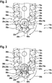
- FIG. 2 shows in detail a machine tool separating device 10a not according to the invention.
- the machine tool separating device 10a comprises a cutting strand 12a and a guide unit 14a for guiding the cutting strand 12a, which, in particular, together with the cutting strand 12a, forms a closed system.
- the machine tool separating device 10a comprises at least one deflection unit 18a arranged on a drive-remote side 16a of the guide unit 14a, which has at least one movably mounted deflecting element 20a for deflecting the cutting strand 12a at least while the cutting strand 12a revolves around the guide unit 14a, which has at least one contact surface 22a comprises an at least temporary contacting of the cutting strand 12a.
- the deflecting element 20a is formed at least essentially free of an extension for engaging the cutting strand 12a.
- the deflecting element 20a viewed in a direction transverse to the movement axis 60a of the deflecting element 20a, in particular viewed transversely to an axis of rotation 74a of the deflecting element 20a, is at least substantially free of teeth.
- the deflecting element 20a is at least essentially free of a roller bearing.
- the deflection element 20a is designed as a deflection disk 24a.
- the deflecting element 20a has a cutout 56a, into which a bearing element 58a of the deflecting unit 18a is inserted for moveable mounting of the deflecting element 20a.
- the bearing element 58a is designed in the form of a bolt.
- the deflecting element 20a is rotatably mounted about the bearing element 58a.
- the axis of rotation 74a of the deflecting element 20a runs at least substantially perpendicular to the cutting plane of the cutting strand 12a.
- a direction of rotation 62a of deflecting element 20a is at least substantially in the same direction as a cutting direction 54a of cutting strand 12a.
- the deflecting element 20a is arranged at least substantially symmetrically with respect to a longitudinal axis 34a of the guide unit 14a. It is also conceivable that the deflecting element 20a is arranged in an alternative embodiment at least substantially asymmetrically with respect to the longitudinal axis 34a.
- the deflection element 20a viewed along a direction perpendicular to the longitudinal axis 34a, has a diameter of at least substantially half the width of the guide unit 14a.
- the deflecting element 20a has an at least substantially circular configuration.
- a diameter of the deflecting element 20a has an at least essentially constant dimension in a plane parallel to the cutting plane of the cutting strand 12a, viewed in all directions.
- the deflecting element 20a comprises the contact surface 22a.
- the contact surface 22a is aligned at least substantially perpendicular to the cutting plane of the cutting strand 12a.
- the contact surface 22a runs along the direction of rotation 62a of the deflecting element 20a, at least essentially along an outer circumference 68a of the deflecting element 20a.
- the cutting strand 12a comprises individual cutting strand segments 64a which, when put together, form the cutting strand 12a.
- the individual cutting strand segment 64a has a contact surface 66a for making contact with the deflecting element 20a.
- the contact surface 66a has a rounded configuration.
- the deflecting element 20a and the individual cutting strand segment 64a can at least essentially rest against one another via the contact surface 22a and via the contact surface 66a.
- the contact surface 22a is preferably provided so that the individual cutting strand segment 64a with the contact surface 66a provided for this purpose can move at least substantially relative to the deflection disk 24a parallel to the cutting plane of the cutting strand 12a when the guide unit 14a revolves.
- the contact surface 22a is at least partially designed to reduce friction.
- the guide unit 14a has an inlet region 30a for the cutting strand 12a, at least essentially adjoining the deflecting element 20a, and an outlet region 32a for the cutting strand 12a, which is at least substantially adjoining the deflecting element 20a, which are designed differently.
- the inlet area 30a is preferably configured such that at least one outer line 70a of the inlet area 30a runs at least essentially in the direction of the outer circumference 68a of the deflecting element 20a and / or is at least essentially curved in the direction of the outer circumference 68a of the deflection element 20a and approaches it.
- the outer line 70a of the inlet region 30a runs at least substantially in the tangential direction of the deflecting element 20a. In particular, the outer line 70a approaches a tangent of the deflecting element 20a.
- the outlet area 32a has a greater distance relative to the deflecting element 20a.
- the guide unit 14a has at least one guide element 36a which is designed asymmetrically to the longitudinal axis 34a and which has a receiving area 38a for the deflecting element 20a limited. It is also conceivable that the guide unit 14a has more than one guide element 36a, which are designed asymmetrically to the longitudinal axis 34a and which delimit a receiving area 38a for the deflecting element 20a. At one end facing the deflecting element 20a, the guide element 36a has a curvature which runs at least substantially parallel to the outer circumference 68a of the deflecting element 20a. By means of the end facing the deflection element 20a, the guide element 36a delimits the receiving region 38a for the deflection element 20a on one side.
- the guide element 36a has a transfer extension 40a, which is provided to enable an at least essentially seamless transition of the cutting strand 12a from the guide element 36a to the deflecting element 20a when the cutting strand 12a moves relative to the guide element 36a.
- the transfer extension 40a is at least partially arranged in the inlet area 30a.
- the transfer extension 40a runs at least substantially tangentially in the direction of the outer circumference 68a of the deflecting element 20a.
- the guide element 36a forms the inlet area 30a and / or the outlet area 32a.
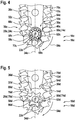
- Figure 3 shows in detail an embodiment of a machine tool separating device 10b according to the invention.
- the deflection unit 18b comprises at least one further deflection element 26b which is at least partially surrounded by the deflection element 20b.
- the further deflecting element 26b is movably mounted and has a sliding surface 28b which is provided to enable a sliding movement of the further deflecting element 26b relative to the deflecting element 20b.
- the further deflecting element 26b is completely surrounded by the deflecting element 20b along the direction of rotation 62b.
- the further deflecting element 26b and the bearing element 58b are located in the recess 56b of the deflecting element 20b arranged.
- the deflecting element 20b and the further deflecting element 26b are rotatably mounted about the bearing element 58b.
- the further deflecting element 26b is mounted at least essentially concentrically with the deflecting element 20b.
- the further deflecting element 26b and the deflecting element 20b are arranged at least essentially symmetrically with respect to the longitudinal axis 34b.
- the further deflecting element 26b is movable relative to the bearing element 58b, to the deflecting element 20b and to the cutting strand 12b.
- the sliding surface 28b of the further deflecting element 26b is arranged perpendicular to the cutting plane of the cutting strand 12b on a border of the further deflecting element 26b facing the deflecting element 20b.
- the sliding surface 28b runs at least substantially parallel to the contact surface 22b for at least temporary contacting of the cutting strand 12b of the deflecting element 20b.
- the sliding surface 28b is designed at least substantially to reduce friction.
- Figure 4 shows in detail a third exemplary embodiment, not according to the invention, of a machine tool separating device 10c.
- the deflection element 20c is mounted on a roller bearing 72c of the deflection unit 18c.
- the roller bearing 72c comprises roller elements, which in this exemplary embodiment are designed as balls. It is also conceivable that, in an alternative exemplary embodiment, the deflecting element 20c is mounted in a different manner that appears sensible to a person skilled in the art, for example on cylindrical elements.
- machine tool separating device 10c shown may refer to the description of the Figures 1 and 2 machine tool separating device 10a shown.
- FIG. 5 shows in detail a fourth exemplary embodiment, not according to the invention, of a machine tool separating device 10d.
- the deflecting element 20d has at least one extension 76d for engaging in the cutting strand 12d.
- the deflection element 20d is mounted at least essentially free of a roller bearing.
- the deflection element 20d is designed in a star shape, in particular it is designed as a deflection star 78d or pinion.
- the contact surface 22d for at least temporary contacting of the cutting strand 12d runs at least substantially parallel to the contact surface 66d of the individual cutting strand segments 64d.
- the deflecting element 20d and the cutting strand 12d move at least substantially uniformly to one another when the guide unit 14d revolves.
- the outer line 70d of the inlet region 30d for the cutting strand 12d runs at least substantially in the direction of the bearing element 58d.
- the inlet area 30d for the cutting strand 12d and the outlet area 32d for the cutting strand 12d have at least essentially the same design.
- the guide element 36d is designed at least substantially symmetrically to the longitudinal axis 34d and at least substantially delimits the receiving area 38d for the deflecting element 20d.
- the guide element 36d has a curvature at an end facing the deflection element 20d.
- machine tool separating device 10d shown may refer to the description of the in Figures 1 and 2 machine tool separating device 10a shown.
Landscapes
- Life Sciences & Earth Sciences (AREA)
- Engineering & Computer Science (AREA)
- Mechanical Engineering (AREA)
- Wood Science & Technology (AREA)
- Forests & Forestry (AREA)
- Milling, Broaching, Filing, Reaming, And Others (AREA)
- Sawing (AREA)
- Surgical Instruments (AREA)
- Harvester Elements (AREA)
Description
- Es ist bereits eine Werkzeugmaschinentrennvorrichtung mit zumindest einem Schneidstrang, mit zumindest einer Führungseinheit zu einer Führung des Schneidstrangs, die insbesondere zusammen mit dem Schneidstrang ein geschlossenes System bildet, und mit zumindest einer an einer antriebsfernen Seite der Führungseinheit angeordneten Umlenkeinheit vorgeschlagen worden. Dabei weist die Umlenkeinheit zumindest ein beweglich gelagertes Umlenkelement zu einer Umlenkung des Schneidstrangs zumindest während eines Umlaufens des Schneidstrangs um die Führungseinheit auf, das zumindest eine Kontaktfläche zu einer zumindest temporären Kontaktierung des Schneidstrangs umfasst. Das Umlenkelement weist zumindest einen Fortsatz zu einem Eingriff in den Schneidstrang auf und ist insbesondere als Umlenkstern ausgebildet.
- Die Erfindung geht aus von einer Werkzeugmaschinentrennvorrichtung gemäß dem Oberbegriff des Patentanspruchs 1, mit zumindest einem Schneidstrang, mit zumindest einer Führungseinheit zu einer Führung des Schneidstrangs, die insbesondere zusammen mit dem Schneidstrang ein geschlossenes System bildet, und mit zumindest einer an einer antriebsfernen Seite der Führungseinheit angeordneten Umlenkeinheit, die zumindest ein beweglich gelagertes Umlenkelement zu einer Umlenkung des Schneidstrangs zumindest während eines Umlaufens des Schneidstrangs um die Führungseinheit aufweist, das zumindest eine Kontaktfläche zu einer zumindest temporären Kontaktierung des Schneidstrangs umfasst.
- Eine Werkzeugmaschinentrennvorrichtung gemäß dem Oberbegriff des Patentanspruchs 1 geht beispielsweise aus der
US 2 599 608 A hervor. - Die Erfindung sieht eine Werkzeugmaschinentrennvorrichtung gemäß dem Patentanspruch 1 vor.
- In einem Ausführungsbeispiel wird vorgeschlagen, dass das Umlenkelement zumindest im Wesentlichen frei von einem Fortsatz zum Eingriff in den Schneidstrang ausgebildet ist. Unter einem "Schneidstrang" soll hier insbesondere eine Einheit verstanden werden, die dazu vorgesehen ist, einen atomaren Zusammenhalt eines zu bearbeitenden Werkstücks örtlich aufzuheben, insbesondere mittels eines mechanischen Abtrennens und/oder mittels eines mechanischen Abtragens von Werkstoffteilchen des Werkstücks. Bevorzugt ist der Schneidstrang dazu vorgesehen, das Werkstück in zumindest zwei physikalisch voneinander getrennte Teile zu separieren und/oder zumindest teilweise Werkstoffteilchen des Werkstücks ausgehend von einer Oberfläche des Werkstücks abzutrennen und/oder abzutragen. Besonders bevorzugt wird der Schneidstrang in zumindest einem Betriebszustand umlaufend um die Führungseinheit bewegt, insbesondere entlang einer Umfangsrichtung der Führungseinheit der Werkzeugmaschinentrennvorrichtung. Besonders bevorzugt ist der Schneidstrang als Schneidkette ausgebildet. Es ist jedoch auch denkbar, dass der Schneidstrang eine andere, einem Fachmann als sinnvoll erscheinende Ausgestaltung aufweist, wie beispielsweise eine Ausgestaltung als
- Schneidband, an dem mehrere Schneidstrangsegmente des Schneidstrangs angeordnet sind. Bevorzugt weist der Schneidstrang, entlang einer zumindest im Wesentlichen senkrecht zu einer Schneidebene des Schneidstrangs verlaufenden Richtung betrachtet, eine maximale Abmessung kleiner als 4 mm auf. Besonders bevorzugt weist der Schneidstrang, entlang der zumindest im Wesentlichen senkrecht zur Schneidebene des Schneidstrangs verlaufenden Richtung betrachtet, entlang einer Gesamtlänge des Schneidstrangs eine zumindest im Wesentlichen gleichbleibende maximale Abmessung auf. Die maximale Abmessung entspricht entlang der Gesamtlänge des Schneidstrangs bevorzugt einem Wert aus einem Wertebereich von 1 mm bis 3 mm. Die Werkzeugmaschinentrennvorrichtung weist, entlang einer Gesamterstreckung der Werkzeugmaschinentrennvorrichtung betrachtet, eine Gesamtbreite auf, die kleiner ist als 4 mm. Der Schneidstrang ist vorzugsweise dazu vorgesehen, einen Schneidspalt zu erzeugen, welcher entlang der zumindest im Wesentlichen senkrecht zur Schneidebene des Schneidstrangs verlaufenden Richtung betrachtet, eine maximale Abmessung kleiner als 4 mm aufweist.
- Unter einer "Führungseinheit" soll hier insbesondere eine Einheit verstanden werden, die dazu vorgesehen ist, eine Zwangskraft zumindest entlang einer Richtung senkrecht zur Schneidrichtung des Schneidstrangs auf den Schneidstrang auszuüben, um eine Bewegungsmöglichkeit des Schneidstrangs entlang der Schneidrichtung, insbesondere entlang der Umfangsrichtung der Führungseinheit, vorzugeben. Bevorzugt weist die Führungseinheit zumindest ein Führungselement auf, insbesondere eine Führungsnut, durch das der Schneidstrang geführt wird. Bevorzugt ist der Schneidstrang, in der Schneidebene des Schneidstrangs betrachtet, entlang eines gesamten Umfangs der Führungseinheit durch die Führungseinheit mittels des Führungselements, insbesondere der Führungsnut, geführt. Unter einer "Schneidrichtung" soll hier insbesondere eine Richtung verstanden werden, entlang der der Schneidstrang zur Erzeugung eines Schneidspalts und/oder zur Abtrennung und/oder zur Abtragung von Werkstoffteilchen eines zu bearbeitenden Werkstücks in zumindest einem Betriebszustand infolge einer Antriebskraft und/oder eines Antriebsmoments, insbesondere in der Führungseinheit, bewegt wird. Der Ausdruck "vorgesehen" soll hier insbesondere speziell ausgelegt und/oder speziell ausgestattet definieren. Darunter, dass ein Element und/oder eine Einheit zu einer bestimmten Funktion vorgesehen sind/ist, soll insbesondere verstanden werden, dass das Element und/oder die Einheit diese bestimmte Funktion in zumindest einem Anwendungs- und/oder Betriebszustand erfüllen/erfüllt und/oder ausführen/ausführt.
- Der Begriff "geschlossenes System" soll hier insbesondere ein System definieren, das zumindest zwei Komponenten umfasst, die mittels eines Zusammenwirkens in einem abgenommenen Zustand des Systems von einem dem System übergeordneten System, wie beispielsweise der tragbaren Werkzeugmaschine, eine Funktionalität beibehalten und/oder die im abgenommenen Zustand unverlierbar miteinander verbunden sind. Bevorzugt sind die zumindest zwei Komponenten des geschlossenen Systems für einen Bediener zumindest im Wesentlichen unlösbar miteinander verbunden. Unter "zumindest im Wesentlichen unlösbar" soll hier insbesondere eine Verbindung von zumindest zwei Bauteilen verstanden werden, die lediglich unter Zuhilfenahme von Trennwerkzeugen, wie beispielsweise einer Säge, insbesondere einer mechanischen Säge usw. und/oder chemischen Trennmitteln, wie beispielsweise Lösungsmitteln usw. voneinander trennbar sind.
- Unter einer "antriebsfernen Seite der Führungseinheit" soll hier insbesondere eine Seite der Führungseinheit verstanden werden, die bezogen auf eine Mittelebene der Führungseinheit, die zumindest im Wesentlichen senkrecht zur Schneidebene des Schneidstrangs verläuft, einer Seite der Führungseinheit abgewandt ist, an der eine Einleitung einer Antriebskraft zu einem Antrieb des Schneidstrangs erfolgt. Vorzugsweise greift zu einer Einleitung einer Antriebskraft zu einem Antrieb des Schneidstrangs ein Drehmomentübertragungselement der tragbaren Werkzeugmaschine in die Führungseinheit auf eine, einem Fachmann bereits bekannte Art und Weise ein. Es ist jedoch auch denkbar, dass die Werkzeugmaschinentrennvorrichtung ein in der Führungseinheit gelagertes Drehmomentübertragungselement aufweist, das zu einer Einleitung einer Antriebskraft zu einem Antrieb des Schneidstrangs mit einem Abtriebselement der tragbaren Werkzeugmaschine verbindbar ist. Vorzugsweise verläuft die Mittelebene zumindest im Wesentlichen senkrecht zu einer Längsachse der Führungseinheit. Bevorzugt weist die Mittelebene, entlang einer zumindest im Wesentlichen senkrecht zur Mittelebene verlaufenden Richtung betrachtet, zu zwei abgewandten Enden der Führungseinheit zumindest gleiche Abstände auf. Insbesondere weist das Umlenkelement der Umlenkeinheit, insbesondere in einem an der Kopplungsvorrichtung der tragbaren Werkzeugmaschine angeordneten Zustand, einen maximalen Abstand zu einer Bewegungsachse des Drehmomentübertragungselements auf, der kleiner ist als 300 mm, bevorzugt kleiner ist als 150 mm und besonders bevorzugt kleiner ist als 75 mm. Besonders bevorzugt ist der maximale Abstand größer als 10 mm. Insbesondere weist der maximale Abstand einen Wert aus einem Wertebereich von 20 mm bis 220 mm auf. Vorzugsweise weist das Umlenkelement der Umlenkeinheit, insbesondere in einem an der Kopplungsvorrichtung der tragbaren Werkzeugmaschine angeordneten Zustand, einen maximalen Abstand zur Bewegungsachse des Drehmomentübertragungselements auf, der zumindest 80 % einer maximalen Erstreckung der Führungseinheit entlang ihrer Längsachse entspricht. Das Drehmomentübertragungselement ist insbesondere dazu vorgesehen, eine Antriebskraft einer Antriebseinheit der tragbaren Werkzeugmaschine auf den Schneidstrang zu übertragen. Vorzugsweise ist das Drehmomentübertragungselement direkt oder indirekt mit einer Motorwelle der Antriebseinheit verbunden. Die Bewegungsachse des Drehmomentübertragungselements verläuft, insbesondere in einem an der Kopplungsvorrichtung der tragbaren Werkzeugmaschine angeordneten Zustand, zumindest im Wesentlichen senkrecht zur Schneidebene des Schneidstrangs. Das Umlenkelement ist drehbar gelagert. Insbesondere weist das Umlenkelement eine Bewegungsachse auf, die zumindest im Wesentlichen senkrecht zur Schneidebene des Schneidstrangs verläuft. Bevorzugt verläuft die Bewegungsachse des Umlenkelements, insbesondere in einem an der Kopplungsvorrichtung der tragbaren Werkzeugmaschine angeordneten Zustand, zumindest im Wesentlichen parallel zur Bewegungsachse des Drehmomentübertragungselements. Ebenso ist es denkbar, dass das Umlenkelement zusätzlich auf eine andere, einem Fachmann als sinnvoll erscheinende Weise beweglich gelagert ist, wie beispielsweise eine linear bewegliche Lagerung, um zusätzlich als Spannelement zu einer Spannung des Schneidstrangs verwendet werden zu können, oder eine Kombination aus einer linearen und einer drehbaren Lagerung. Das Umlenkelement weist eine Ausnehmung auf, in die ein Lagerungselement der Umlenkeinheit einsetzbar ist. Vorzugsweise lenkt das Umlenkelement den Schneidstrang bei einer Bewegung des Schneidstrangs relativ zur Führungseinheit zumindest im Wesentlichen um mehr als 10°, bevorzugt um mehr als 45° und besonders bevorzugt um weniger als 200° um. Des Weiteren ist es denkbar, dass die Umlenkeinheit zumindest eine von eins abweichende Anzahl an beweglich gelagerten Umlenkelementen umfasst, die gemeinsam zu einer Umlenkung des Schneidstrangs zumindest während eines Umlaufens des Schneidstrangs um die Führungseinheit vorgesehen sind.
- Unter einer "zumindest temporären Kontaktierung des Schneidstrangs" soll hier insbesondere verstanden werden, dass zumindest bei einer Anordnung des Schneidstrangs an der Führungseinheit der Schneidstrang an das Umlenkelement anlegbar ist bzw. mit diesem in Kontakt bringbar ist und/oder dass während des Umlaufens des Schneidstrangs um die Führungseinheit zumindest ein Schneidstrangsegment des Schneidstrangs zumindest für einen kurzen Zeitraum in Berührung mit dem Umlenkelement gelangt. Insbesondere ist die Kontaktfläche des Umlenkelements aus zumindest einem gehärteten Werkstoff gebildet. Ebenso ist es denkbar, dass die Kontaktfläche alternativ oder zusätzlich mittels anderer, einem Fachmann als sinnvoll erscheinender Verfahren behandelt ist, um zumindest eine vorteilhafte Kontakteigenschaft mit dem Schneidstrang zu ermöglichen. Vorzugsweise ist die Kontaktfläche des Umlenkelements zumindest im Wesentlichen senkrecht zur Schneidebene des Schneidstrangs ausgerichtet. Insbesondere ist an der Kontaktfläche des Umlenkelements zumindest ein Schneidstrangsegment des Schneidstrangs anlegbar, bevorzugt ist zumindest das Schneidstrangsegment des Schneidstrangs mit einer dafür vorgesehenen Berührfläche des Schneidstrangsegments an der Kontaktfläche des Umlenkelements anlegbar. Bevorzugt bildet die Kontaktfläche des Umlenkelements eine Außenfläche des Umlenkelements.
- Unter "frei von einem Fortsatz zum Eingriff in den Schneidstrang ausgebildet" soll hier verstanden werden, dass zumindest ein maximaler Fortsatz, insbesondere alle Fortsätze, des Umlenkelements, der/die zumindest im Wesentlichen quer zur Bewegungsachse des Umlenkelements ausgerichtet ist/sind, eine maximale Erstreckung von weniger als 5 mm, bevorzugt von weniger als 1 mm und besonders bevorzugt von weniger als 0,1 mm aufweist/aufweisen, insbesondere ausgehend von einer Außenfläche des Umlenkelements, die einen kleinsten Abstand zur Bewegungsachse des Umlenkelements aufweist. Vorzugsweise weist die Oberfläche des Umlenkelements eine maximale Rauheit von weniger als 500 µm, bevorzugt weniger als 200 µm und besonders bevorzugt von weniger als 100 µm auf. Ebenso ist es denkbar, dass das Umlenkelement zumindest im Wesentlichen eine gewellte Oberfläche aufweist. Durch die erfindungsgemäße Ausgestaltung der Werkzeugmaschinentrennvorrichtung kann vorteilhaft Reibung an der Umlenkeinheit und am Schneidstrang gering gehalten werden. Es kann ferner eine Wärmeentwicklung an der Umlenkeinheit und am Schneidstrang gering gehalten werden. Ferner kann vorteilhaft eine Verschleißreduzierung sowohl der Umlenkeinheit als auch des Schneidstrangs erreicht werden und somit eine Wahrscheinlichkeit eines Blockierens des Schneidstrangs beim Umlaufen um die Führungseinheit gering gehalten werden. Es können vorteilhaft im Vergleich zum Stand der Technik der Schneidstrang straffer gespannt und/oder bei gleicher Antriebsleistung der Antriebseinheit zu einer Bewegung des Schneidstrangs eine hohe Schnittleistung erreicht werden. Des Weiteren können bei der Herstellung der erfindungsgemäßen Werkzeugmaschinentrennvorrichtung vorteilhaft Kosten eingespart werden. Ebenso können vorteilhaft bei der Montage des Schneidstrangs an der Führungseinheit Zeit und somit Kosten eingespart werden. Ferner kann in Abhängigkeit von einer Stärke von Reibungskräften zwischen dem Schneidstrang und der Kontaktfläche des Umlenkelements ein vorteilhaftes Umspringen zwischen einem Gleiten des Schneidstrangs an der Kontaktfläche des Umlenkelements und einer simultanen Bewegung von Schneidstrang und Umlenkelement erreicht werden.
- Das Umlenkelement ist zumindest im Wesentlichen frei von einem Wälzlager gelagert. Insbesondere ist das Umlenkelement zumindest im Wesentlichen frei von Wälzelementen gelagert, wie beispielsweise Kugeln, Tonnen, Nadeln, Zylinder o. dgl. Mittels der erfindungsgemäßen Ausgestaltung können bei der Herstellung der erfindungsgemäßen Werkzeugmaschinentrennvorrichtung vorteilhaft zusätzliche Kosten eingespart werden. Ebenso kann vorteilhaft ein Montageaufwand bei einer Montage des Umlenkelements in der Führungseinheit reduziert werden.
- Ferner wird vorgeschlagen, dass das Umlenkelement als Umlenkscheibe ausgebildet ist. Vorzugsweise weist das Umlenkelement zumindest im Wesentlichen eine maximale Dicke von weniger als 5 mm, bevorzugt von weniger als 2 mm und besonders bevorzugt von weniger als 1 mm auf. Das Umlenkelement weist vorzugsweise zumindest im Wesentlichen einen maximalen Abstand zu einer äußeren Umrandung der Führungseinheit von weniger als 3 mm, bevorzugt von weniger als 2 mm und besonders bevorzugt von weniger als 1 mm auf. Besonders bevorzugt ist der maximale Abstand zur äußeren Umrandung größer als 0,1 mm. Die Kontaktfläche des Umlenkelements ist vorzugsweise dazu vorgesehen, dass der Schneidstrang beim Umlaufen der Führungseinheit an der Kontaktfläche des Umlenkelements gleiten kann, insbesondere kann zumindest das Schneidstrangsegment des Schneidstrangs mit der dafür vorgesehenen Berührfläche an der Kontaktfläche des Umlenkelements gleiten. Mittels der erfindungsgemäßen Ausgestaltung der Werkzeugmaschinentrennvorrichtung kann vorteilhaft ein kostengünstig zu produzierendes Umlenkelement realisiert werden.
- Des Weiteren wird vorgeschlagen, dass das Umlenkelement eine zumindest im Wesentlichen kreisförmige Ausgestaltung aufweist. Unter einer "zumindest im Wesentlichen kreisförmigen Ausgestaltung des Umlenkelements" soll hier insbesondere eine Ausgestaltung des Umlenkelements verstanden werden, bei der eine Außenkontur des Umlenkelements, in einer zumindest im Wesentlichen senkrecht zur Bewegungsachse des Umlenkelements verlaufenden Ebene betrachtet, eine Form eines Kreises aufweist, die eine maximale Abweichung von einer idealen Kreisform von maximal 20% aufweist, oder die sich einer Form einer Ellipse annähert, wobei eine große und eine kleine Halbachse der Ellipse in einem maximalen Verhältnis von weniger als 2:1, bevorzugt weniger als 3:2 und besonders bevorzugt weniger als 4:3 stehen. Insbesondere weist die Umlenkscheibe zumindest im Wesentlichen einen maximalen Durchmesser von weniger als 20 mm, bevorzugt von weniger als 10 mm und besonders bevorzugt von weniger als 5 mm auf. Der Durchmesser der Umlenkscheibe beträgt insbesondere zumindest im Wesentlichen das 20-fache, bevorzugt das 10-fache und besonders bevorzugt das 5-fache der Dicke der Umlenkscheibe. Mittels der erfindungsgemäßen Ausgestaltung kann vorteilhaft eine konstruktiv einfache Ausgestaltung zu einer Ermöglichung einer großen Gleitfläche zwischen Schneidstrang und Umlenkelement realisiert werden.
- Zudem wird vorgeschlagen, dass die Kontaktfläche des Umlenkelements zumindest teilweise reibungsreduzierend ausgebildet ist. Die Kontaktfläche des Umlenkelements ist vorzugsweise zumindest im Wesentlichen oberflächenbehandelt. Die Kontaktfläche des Umlenkelements weist bevorzugt zumindest im Wesentlichen eine chemische, physikalische oder eine andere, einem Fachmann als sinnvoll erscheinende Oberflächenbehandlung auf. Vorzugsweise umfasst die Kontaktfläche des Umlenkelements zumindest im Wesentlichen eine teilweise chemische, physikalische oder eine andere, einem Fachmann als sinnvoll erscheinende Beschichtung zu einer Reibungsreduzierung auf. Insbesondere ist die Kontaktfläche des Umlenkelements oberflächenstrukturiert, bevorzugt mikrostrukturiert und besonders bevorzugt nanostrukturiert ausgebildet. Das Umlenkelement ist vorzugsweise aus einem Werkstoff gebildet, der eine zumindest im Wesentlichen reibungsreduzierend Ausgestaltung des Umlenkelements ermöglicht, wie beispielsweise Graphit o. dgl. Durch die erfindungsgemäße Ausgestaltung der Werkzeugmaschinentrennvorrichtung kann vorteilhaft eine Erwärmung des Umlenkelements und des Schneidstrangs reduziert und ein Verschleiß des Umlenkelements und des Schneidstrangs weiter minimiert werden. Zudem kann vorteilhaft eine lange Haltbarkeit des Umlenkelements und des Schneidstrangs erreicht werden.
- Die Umlenkeinheit umfasst zumindest ein weiteres Umlenkelement, das zumindest teilweise von dem Umlenkelement umgeben ist. Das weitere Umlenkelement ist vorzugsweise entlang einer Rotationsrichtung des Umlenkelements zumindest im Wesentlichen vollständig vom Umlenkelement umgeben. Das weitere Umlenkelement ist mit dem Umlenkelement zumindest im Wesentlichen konzentrisch gelagert. Mittels der erfindungsgemäßen Ausgestaltung der Werkzeugmaschinentrennvorrichtung kann vorteilhaft eine Verringerung von Reibungseinflüssen auf das Umlenkelement erreicht werden. Es kann vorteilhaft eine reibungsverringerte Umlenkung des Schneidstrangs beim Umlaufen der Führungseinheit ermöglicht werden.
- Gemäß der Erfindung ist das weitere Umlenkelement beweglich gelagert und weist eine Gleitfläche auf, die dazu vorgesehen ist, eine Gleitbewegung des Umlenkelements relativ zum Umlenkelement zu ermöglichen. Das weitere Umlenkelement ist beweglich gelagert, insbesondere drehbar gelagert. Ebenso ist es denkbar, dass das weitere Umlenkelement zusätzlich linear beweglich gelagert ist. Das weitere Umlenkelement ist relativ zum Umlenkelement und zum Schneidstrang bewegbar. Insbesondere verläuft die Gleitfläche des weiteren Umlenkelement zumindest im Wesentlichen senkrecht zur Schneidebene des Schneidstrangs. Die Gleitfläche des weiteren Umlenkelements bildet insbesondere eine Außenfläche des weiteren Umlenkelements. Besonders bevorzugt ist die Gleitfläche zumindest im Wesentlichen reibungsreduzierend ausgebildet. Diesbezüglich weist die Gleitfläche zumindest im Wesentlichen alle Merkmale der Kontaktfläche des Umlenkelements auf, wie beispielsweise eine reibungsreduzierende Beschichtung usw. Mittels der erfindungsgemäßen Ausgestaltung der Werkzeugmaschinentrennvorrichtung kann vorteilhaft das Umlenkelement reibungsoptimiert gelagert werden. Es kann vorteilhaft die Reibung zwischen dem Umlenkelement und dem weiteren Umlenkelement und somit die Wärmeentwicklung zwischen diesen beiden Elementen gering gehalten werden, um besonders vorteilhaft einen Verschleiß des Umlenkelements und des weiteren Umlenkelements zu verringern.
- Zudem wird vorgeschlagen, dass die Führungseinheit einen zumindest im Wesentlichen an das Umlenkelement angrenzenden Einlaufbereich für den Schneidstrang und einen zumindest im Wesentlichen an das Umlenkelement angrenzenden Auslaufbereich für den Schneidstrangs aufweist, die unterschiedlich ausgebildet sind. Unter einem "Einlaufbereich" soll hier insbesondere ein Bereich der Führungseinheit verstanden werden, in welchem der Schneidstrang beim Umlaufen der Führungseinheit zum Umlenkelement hin läuft, insbesondere betrachtet in einem Bereich der Führungseinheit mit einem Abstand zum Umlenkelement, der kleiner ist als 10 mm. Unter einem "Auslaufbereich" soll hier insbesondere ein Bereich der Führungseinheit verstanden werden, in welchem der Schneidstrang beim Umlaufen der Führungseinheit vom Umlenkelement weg läuft, insbesondere betrachtet in einem Bereich der Führungseinheit mit einem Abstand zum Umlenkelement, der kleiner ist als 10 mm. Im Einlaufbereich bewegt sich der Schneidstrang beim Umlaufen der Führungseinheit vorzugsweise zumindest im Wesentlichen in entgegengesetzter Richtung zum Auslaufbereich. Der Einlaufbereich ist vorzugsweise derart ausgestaltet, dass zumindest eine Außenlinie des Einlaufbereichs zumindest im Wesentlichen in Richtung eines Außenumfangs des Umlenkelements verläuft und/oder zumindest im Wesentlichen in Richtung des Außenumfangs des Umlenkelements gekrümmt ist und sich diesem annähert. Insbesondere verläuft die Außenlinie des Einlaufbereichs zumindest annähernd in tangentialer Richtung des Umlenkelements. Der Auslaufbereich weist vorzugsweise zumindest im Wesentlichen einen im Vergleich zum Einlaufbereich einen größeren Abstand relativ zum Umlenkelement auf. Der Auslaufbereich ist vorzugsweise derart ausgestaltet, dass zumindest eine Außenlinie des Auslaufbereichs zumindest im Wesentlichen in Richtung der Bewegungsachse des Umlenkelements verläuft und/oder zumindest im Wesentlichen in Richtung der Bewegungsachse des Umlenkelements gekrümmt ist. Der Auslaufbereich weist im Vergleich zum Einlaufbereich einen größeren Krümmungsradius auf. Eine unterschiedliche Ausbildung von Einlaufbereich und Auslaufbereich kann insbesondere dadurch erreicht werden, dass die Führungseinheit zumindest ein Führungselement aufweist, das unsymmetrisch zur Längsachse ausgebildet ist. Denkbar ist auch, dass die Führungseinheit zumindest zwei Führungselemente aufweist, die unterschiedlich ausgebildet sind, oder dass die Führungseinheit zumindest mehr als zwei Führungselemente aufweist, die unterschiedlich ausgebildet sind. Es kann vorteilhaft eine sichere Führung des Schneidstrangs beim Umlaufen der Führungseinheit zum Umlenkelement hin und vom Umlenkelement weg erreicht werden. Es kann vorteilhaft ein Verhaken des Schneidstrangs und somit eine Wahrscheinlichkeit eines Blockierens des Schneidstrangs gering gehalten werden. Ferner kann ein zuverlässiges Umlaufen der Führungseinheit des Schneidstrangs ermöglicht werden.
- Vorteilhafterweise wird vorgeschlagen, dass die Führungseinheit eine Längsachse und zumindest ein Führungselement aufweist, das unsymmetrisch zur Längsachse ausgebildet ist und einen Aufnahmebereich für das Umlenkelement begrenzt. Ebenso ist es denkbar, dass die Führungseinheit mehr als ein Führungselement aufweist, die unsymmetrisch zur Längsachse ausgebildet sind und einen Aufnahmebereich für das Umlenkelement begrenzen. Insbesondere verläuft die Längsachse der Führungseinheit zumindest im Wesentlichen in der Schneidebene des Schneidstrangs und zumindest im Wesentlichen senkrecht zur Mittelebene der Führungseinheit. Das Führungselement der Führungseinheit umfasst an einem dem Umlenkelement zugewandten Ende des Führungselements zumindest im Wesentlichen den Einlaufbereich und/oder den Auslaufbereich. In einer alternativen Ausgestaltung der Werkzeugmaschinentrennvorrichtung es denkbar, dass das Führungselement insbesondere mehrteilig ausgebildet, bevorzugt dreiteilig ausgebildet und besonders bevorzugt zweiteilig ausgebildet ist. Es kann besonders einfach und kostengünstig eine optimale Kinematik des Schneidstrangs beim Umlaufen der Führungseinheit zum Umlenkelement hin und vom Umlenkelement weg erreicht werden.
- Des Weiteren wird vorgeschlagen, dass die Führungseinheit zumindest ein Führungselement aufweist, das zumindest einen Überführungsfortsatz aufweist, der dazu vorgesehen ist, bei einer Bewegung des Schneidstrangs relativ zum Führungselement einen zumindest im Wesentlichen nahtlosen Übergang des Schneidstrangs von dem Führungselement auf das Umlenkelement zu ermöglichen. Der Überführungsfortsatz verläuft zumindest im Wesentlichen tangential in Richtung des Außenumfangs des Umlenkelements. Der Überführungsfortsatz weist insbesondere einen maximalen Abstand zum Umlenkelement von weniger als 3 mm auf, bevorzugt weniger als 2 mm auf und besonders bevorzugt von weniger als 1 mm auf. Es kann vorteilhaft eine im Wesentlichen ununterbrochene Führung des Schneidstrangs beim Umlaufen der Führungseinheit hin zum Umlenkelement erreicht werden. Es kann besonders vorteilhaft ein zuverlässiges Führen der Schneidstrangsegmente des Schneidstrangs hin zum Umlenkelement ermöglicht werden. Ferner kann vorteilhaft erreicht werden, dass die Schneidstrangsegmente beim Umlaufen der Führungseinheit hin zum Umlenkelement zumindest im Wesentlichen tangential an das Umlenkelement herangeführt werden.
- Zudem wird ein Werkzeugmaschinensystem mit zumindest einer erfindungsgemäßen Werkzeugmaschinentrennvorrichtung und mit zumindest einer tragbaren Werkzeugmaschine vorgeschlagen, die zumindest eine Kopplungsvorrichtung zu einer formschlüssigen und/oder kraftschlüssigen Kopplung mit der erfindungsgemäßen Werkzeugmaschinentrennvorrichtung aufweist. Unter einer "tragbaren Werkzeugmaschine" soll hier insbesondere eine Werkzeugmaschine, insbesondere eine Handwerkzeugmaschine, verstanden werden, die von einem Bediener transportmaschinenlos transportiert werden kann. Die tragbare Werkzeugmaschine weist insbesondere eine Masse auf, die kleiner ist als 40 kg, bevorzugt kleiner als 10 kg und besonders bevorzugt kleiner als 5 kg. Es kann vorteilhaft ein Werkzeugmaschinensystem realisiert werden, bei welchem Reibungskräfte an der Umlenkeinheit und am Schneidstrang verringert und somit eine Wärmeentwicklung an der Umlenkeinheit und am Schneidstrang gering gehalten werden. Ferner kann vorteilhaft ein Werkzeugmaschinensystem ermöglicht werden, bei welchem Verschleiß sowohl an der Umlenkeinheit als auch am Schneidstrang gering gehalten und somit ein Blockieren des Schneidstrangs beim Umlaufen um die Führungseinheit vermieden werden kann. Beim erfindungsgemäßen Werkzeugmaschinensystem können vorteilhaft im Vergleich zum Stand der Technik der Schneidstrang straffer gespannt und/oder bei gleicher Antriebsleistung einer Antriebseinheit zu einer Bewegung des Schneidstrangs eine erhöhte Schnittleistung erreicht werden. Insbesondere kann vorteilhaft eine Verteilung von Reibung und von Verschleiß zwischen der Umlenkeinheit und dem Schneidstrang erreicht werden. Des Weiteren können bei der Herstellung der erfindungsgemäßen Werkzeugmaschinentrennvorrichtung vorteilhaft zusätzliche Kosten eingespart werden. Ebenso kann vorteilhaft ein Montageaufwand der Führungseinheit reduziert werden.
- Die erfindungsgemäße Werkzeugmaschinentrennvorrichtung und/oder das erfindungsgemäße Werkzeugmaschinensystem soll/sollen hierbei nicht auf die oben beschriebene Anwendung und Ausführungsform beschränkt sein. Insbesondere können die erfindungsgemäße Werkzeugmaschinentrennvorrichtung und/oder das erfindungsgemäße Werkzeugmaschinensystem zu einer Erfüllung einer hierin beschriebenen Funktionsweise eine von einer hierin genannten Anzahl von einzelnen Elementen, Bauteilen und Einheiten abweichende Anzahl aufweisen. Zudem sollen bei den in dieser Offenbarung angegebenen Wertebereichen auch innerhalb der genannten Grenzen liegende Werte als offenbart und als beliebig einsetzbar gelten.
- Weitere Vorteile ergeben sich aus der folgenden Zeichnungsbeschreibung. In der Zeichnung sind vier Ausführungsbeispiele dargestellt. Die Zeichnung, die Beschreibung und die Ansprüche enthalten zahlreiche Merkmale in Kombination. Der Fachmann wird die Merkmale zweckmäßigerweise auch einzeln betrachten und zu sinnvollen weiteren Kombinationen zusammenfassen.
-
- Fig. 1
- eine erfindungsgemäße tragbare Werkzeugmaschine mit einer erfindungsgemäßen Werkzeugmaschinentrennvorrichtung in einer schematischen Darstellung,
- Fig. 2
- eine Detailansicht eines nicht erfindungsgemäßen ersten Ausführungsbeispiels einer Werkzeugmaschinentrennvorrichtung in einer schematischen Darstellung,
- Fig. 3
- eine Detailansicht eines erfindungsgemäßen zweiten Ausführungsbeispiels einer Werkzeugmaschinentrennvorrichtung in einer schematischen Darstellung,
- Fig. 4
- eine Detailansicht eines nicht erfindungsgemäßen dritten Ausführungsbeispiels einer Werkzeugmaschinentrennvorrichtung in einer schematischen Darstellung und
- Fig. 5
- eine Detailansicht eines nicht erfindungsgemäßen vierten Ausführungsbeispiels einer Werkzeugmaschinentrennvorrichtung in einer schematischen Darstellung.
-
Figur 1 zeigt eine tragbare Werkzeugmaschine 42a mit einer erfindungsgemäßen Werkzeugmaschinentrennvorrichtung 10a, die zusammen ein Werkzeugmaschinensystem bilden. Die tragbare Werkzeugmaschine 42a weist zumindest eine Kopplungsvorrichtung 44a zu einer formschlüssigen und/oder kraftschlüssigen Kopplung mit der Werkzeugmaschinentrennvorrichtung 10a auf. Die Kopplungsvorrichtung 44a kann als Bajonettverschluss, Schnappverschluss und/oder als eine andere, einem Fachmann als sinnvoll erscheinende Kopplungsvorrichtung ausgebildet sein. Die Werkzeugmaschinentrennvorrichtung 10a oder die tragbare Werkzeugmaschine 42a weist zumindest ein Drehmomentübertragungselement 46a auf. Das Drehmomentübertragungselement 46a kann als Zahnrad, insbesondere als Ritzel, ausgebildet sein. Die Werkzeugmaschinentrennvorrichtung 10a umfasst zumindest einen Schneidstrang 12a und zumindest eine Führungseinheit 14a zu einer Führung des Schneidstrangs 12a. Die Führungseinheit 14a bildet zusammen mit dem Schneidstrang 12a ein geschlossenes System. Das Drehmomentübertragungselement 46a ist zu einer Übertragung einer Antriebskraft einer Antriebseinheit 48a der tragbaren Werkzeugmaschine 42a auf den Schneidstrang 12a vorgesehen. - Die tragbare Werkzeugmaschine 42a weist zumindest ein Werkzeugmaschinengehäuse 50a auf, das die Antriebseinheit 48a und eine Getriebeeinheit 52a der tragbaren Werkzeugmaschine 42a umschließt. Die Antriebseinheit 48a und die Getriebeeinheit 52a sind zu einer Erzeugung eines auf die Werkzeugmaschinentrennvorrichtung 10a übertragbaren Antriebsmoments auf eine, einem Fachmann bereits bekannte Art und Weise wirkungsmäßig miteinander verbunden. Die Getriebeeinheit 52a ist bevorzugt als Winkelgetriebe ausgebildet. Die Antriebseinheit 48a ist bevorzugt als Elektromotoreinheit ausgebildet. Es ist jedoch auch denkbar, dass die Antriebseinheit 48a und/oder die Getriebeeinheit 52a eine andere, einem Fachmann als sinnvoll erscheinende Ausgestaltung aufweisen, wie beispielsweise eine Ausgestaltung der Getriebeeinheit 52a als Schneckengetriebe usw. Die Antriebseinheit 48a ist dazu vorgesehen, den Schneidstrang 12a der Werkzeugmaschinentrennvorrichtung 10a in zumindest einem Betriebszustand über die Getriebeeinheit 52a anzutreiben. Der Schneidstrangs 12a wird in der Führungseinheit 14a der Werkzeugmaschinentrennvorrichtung 10a entlang einer Schneidrichtung 54a des Schneidstrangs 12a in der Führungseinheit 14a bewegt, insbesondere relativ zur Führungseinheit 14a.
-
Figur 2 zeigt im Detail eine nicht erfindungsgemäße Werkzeugmaschinentrennvorrichtung 10a. Die Werkzeugmaschinentrennvorrichtung 10a umfasst einen Schneidstrang 12a und eine Führungseinheit 14a zu einer Führung des Schneidstrangs 12a, die insbesondere zusammen mit dem Schneidstrang 12a ein geschlossenes System bildet. Die Werkzeugmaschinentrennvorrichtung 10a umfasst zumindest eine an einer antriebsfernen Seite 16a der Führungseinheit 14a angeordnete Umlenkeinheit 18a, die zumindest ein beweglich gelagertes Umlenkelement 20a zu einer Umlenkung des Schneidstrangs 12a zumindest während eines Umlaufens des Schneidstrangs 12a um die Führungseinheit 14a aufweist, das zumindest eine Kontaktfläche 22a zu einer zumindest temporären Kontaktierung des Schneidstrangs 12a umfasst. Das Umlenkelement 20a ist zumindest im Wesentlichen frei von einem Fortsatz zum Eingriff in den Schneidstrang 12a ausgebildet. Bevorzugt ist das Umlenkelement 20a in einer Richtung quer zur Bewegungsachse 60a des Umlenkelements 20a betrachtet, insbesondere quer zu einer Rotationsachse 74a des Umlenkelements 20a betrachtet, zumindest im Wesentlichen frei von Zähnen ausgebildet. Das Umlenkelement 20a ist zumindest im Wesentlichen frei von einem Wälzlager gelagert. Das Umlenkelement 20a ist als Umlenkscheibe 24a ausgebildet. In diesem Ausführungsbeispiel weist das Umlenkelement 20a eine Aussparung 56a auf, in die ein Lagerungselement 58a der Umlenkeinheit 18a zu einer beweglichen Lagerung des Umlenkelements 20a eingesetzt ist. Das Lagerungselement 58a ist in Form eines Bolzens ausgebildet. Das Umlenkelement 20a ist drehbar um das Lagerungselement 58a gelagert. Die Rotationsachse 74a des Umlenkelements 20a verläuft zumindest im Wesentlichen senkrecht zur Schneidebene des Schneidstrangs 12a. Eine Rotationsrichtung 62a des Umlenkelements 20a ist zumindest im Wesentlichen gleichgerichtet zu einer Schneidrichtung 54a des Schneidstrangs 12a. Das Umlenkelement 20a ist zumindest im Wesentlichen symmetrisch bezüglich einer Längsachse 34a der Führungseinheit 14a angeordnet. Ebenso ist es denkbar, dass das Umlenkelement 20a in einer alternativen Ausgestaltung zumindest im Wesentlichen asymmetrisch bezüglich der Längsachse 34a angeordnet ist. Das Umlenkelement 20a weist entlang einer Richtung senkrecht zur Längsachse 34a betrachtet einen Durchmesser von zumindest im Wesentlichen einer halben Breite der Führungseinheit 14a auf. Das Umlenkelement 20a weist eine zumindest im Wesentlichen kreisförmige Ausgestaltung auf. Ein Durchmesser des Umlenkelements 20a weist in einer Ebene parallel zur Schneidebene des Schneidstrangs 12a betrachtet in alle Richtungen eine zumindest im Wesentlichen konstante Abmessung auf. Zu einer zumindest temporären Kontaktierung des Schneidstrangs 12a umfasst das Umlenkelement 20a die Kontaktfläche 22a. Die Kontaktfläche 22a ist zumindest im Wesentlichen senkrecht zur Schneidebene des Schneidstrangs 12a ausgerichtet. Die Kontaktfläche 22a verläuft entlang der Rotationsrichtung 62a des Umlenkelements 20a betrachtet zumindest im Wesentlichen entlang eines Außenumfangs 68a des Umlenkelements 20a. Der Schneidstrang 12a umfasst einzelne Schneidstrangsegmente 64a, die zusammengesetzt den Schneidstrang 12a bilden. Das einzelne Schneidstrangsegment 64a weist eine Berührfläche 66a zu einer Kontaktbildung mit dem Umlenkelement 20a auf. Die Berührfläche 66a weist eine abgerundete Ausgestaltung auf. Über die Kontaktfläche 22a und über die Berührfläche 66a sind das Umlenkelement 20a und das einzelne Schneidstrangsegment 64a zumindest im Wesentlichen aneinander anlegbar. Die Kontaktfläche 22a ist vorzugsweise dazu vorgesehen, dass sich das einzelne Schneidstrangsegment 64a mit der dafür vorgesehenen Berührfläche 66a beim Umlaufen der Führungseinheit 14a zumindest im Wesentlichen relativ zur Umlenkscheibe 24a parallel zur Schneidebene des Schneidstrangs 12a bewegen kann. Die Kontaktfläche 22a ist zumindest teilweise reibungsreduzierend ausgebildet. Die Führungseinheit 14a weist einen zumindest im Wesentlichen an das Umlenkelement 20a angrenzenden Einlaufbereich 30a für den Schneidstrang 12a und einen zumindest im Wesentlichen an das Umlenkelement 20a angrenzenden Auslaufbereich 32a für den Schneidstrang 12a auf, die unterschiedlich ausgebildet sind. Der Einlaufbereich 30a ist vorzugsweise derart ausgestaltet, dass zumindest eine Außenlinie 70a des Einlaufbereichs 30a zumindest im Wesentlichen in Richtung des Außenumfangs 68a des Umlenkelements 20a verläuft und/oder zumindest im Wesentlichen in Richtung des Außenumfangs 68a des Umlenkelements 20a gekrümmt ist und sich diesem annähert. Die Außenlinie 70a des Einlaufbereichs 30a verläuft zumindest im Wesentlichen in tangentialer Richtung des Umlenkelements 20a. Insbesondere nähert sich die Außenlinie 70a einer Tangente des Umlenkelements 20a an. Der Auslaufbereich 32a weist einen im Vergleich zum Einlaufbereich 30a größeren Abstand relativ zum Umlenkelement 20a auf. Die Führungseinheit 14a weist zumindest ein Führungselement 36a auf, das unsymmetrisch zur Längsachse 34a ausgebildet ist und das einen Aufnahmebereich 38a für das Umlenkelement 20a begrenzt. Ebenso ist es denkbar, dass die Führungseinheit 14a mehr als ein Führungselement 36a aufweist, die unsymmetrisch zur Längsachse 34a ausgebildet sind und die einen Aufnahmebereich 38a für das Umlenkelement 20a begrenzen. Das Führungselement 36a weist an einem dem Umlenkelement 20a zugewandten Ende eine Krümmung auf, die zumindest im Wesentlichen parallel zum Außenumfang 68a des Umlenkelements 20a verläuft. Mittels des dem Umlenkelement 20a zugewandten Endes begrenzt das Führungselement 36a einseitig den Aufnahmebereich 38a für das Umlenkelement 20a. Das Führungselement 36a weist einen Überführungsfortsatz 40a auf, der dazu vorgesehen ist, bei einer Bewegung des Schneidstrangs 12a relativ zum Führungselement 36a einen zumindest im Wesentlich nahtlosen Übergang des Schneidstrangs 12a von dem Führungselement 36a auf das Umlenkelement 20a zu ermöglichen. Der Überführungsfortsatz 40a ist zumindest teilweise im Einlaufbereich 30a angeordnet. Der Überführungsfortsatz 40a verläuft zumindest im Wesentlichen tangential in Richtung des Außenumfangs 68a des Umlenkelements 20a. Das Führungselement 36a bildet den Einlaufbereich 30a und/oder den Auslaufbereich 32a. - In den
Figuren 3 bis 5 sind weitere Ausführungsbeispiele gezeigt. Die nachfolgenden Beschreibungen und die Zeichnungen beschränken sich im Wesentlichen auf die Unterschiede zwischen den Ausführungsbeispielen, wobei bezüglich gleich bezeichneter Bauteile, insbesondere in Bezug auf Bauteile mit gleichen Bezugszeichen, grundsätzlich auch auf die Zeichnungen und/oder die Beschreibung der anderen Ausführungsbeispiele, insbesondere derFiguren 1 und2 , verwiesen werden kann. Zu einer Unterscheidung der einzelnen Ausführungsbeispiele sind in denFiguren 2 bis 5 den jeweiligen Bezugszeichen die Buchstaben a bis d nachgestellt. In den Ausführungsbeispielen derFiguren 3 bis 5 ist der Buchstabe a durch die Buchstaben b bis d ersetzt. -
Figur 3 zeigt im Detail ein Ausführungsbeispiel einer erfindungsgemäßen Werkzeugmaschinentrennvorrichtung 10b. In diesem Ausführungsbeispiel umfasst die Umlenkeinheit 18b zumindest ein weiteres Umlenkelement 26b, das zumindest teilweise von dem Umlenkelement 20b umgeben ist. Das weitere Umlenkelement 26b ist beweglich gelagert und weist eine Gleitfläche 28b auf, die dazu vorgesehen ist, eine Gleitbewegung des weiteren Umlenkelements 26b relativ zum Umlenkelement 20b zu ermöglichen. Das weitere Umlenkelement 26b ist entlang der Rotationsrichtung 62b vollständig vom Umlenkelement 20b umgeben. In der Aussparung 56b des Umlenkelements 20b sind das weitere Umlenkelement 26b und das Lagerungselement 58b angeordnet. Das Umlenkelement 20b und das weitere Umlenkelement 26b sind drehbar um das Lagerungselement 58b gelagert. Das weitere Umlenkelement 26b ist mit dem Umlenkelement 20b zumindest im Wesentlichen konzentrisch gelagert. Das weitere Umlenkelement 26b und das Umlenkelement 20b sind bezüglich der Längsachse 34b zumindest im Wesentlichen symmetrisch angeordnet. Das weitere Umlenkelement 26b ist relativ zum Lagerungselement 58b, zum Umlenkelement 20b und zum Schneidstrang 12b bewegbar. Die Gleitfläche 28b des weiteren Umlenkelements 26b ist senkrecht zur Schneidebene des Schneidstrangs 12b an einer dem Umlenkelement 20b zugewandten Umrandung des weiteren Umlenkelements 26b angeordnet. Die Gleitfläche 28b verläuft zumindest im Wesentlichen parallel zur Kontaktfläche 22b zu einer zumindest temporären Kontaktierung des Schneidstrangs 12b des Umlenkelements 20b. Die Gleitfläche 28b ist zumindest im Wesentlichen reibungsreduzierend ausgebildet. Hinsichtlich weiterer Merkmale und Funktionen der in derFigur 3 dargestellten Werkzeugmaschinentrennvorrichtung 10b darf auf die Beschreibung der in denFiguren 1 und2 dargestellten Werkzeugmaschinentrennvorrichtung 10a verwiesen werden. -
Figur 4 zeigt im Detail ein nicht erfindungsgemäßes drittes Ausführungsbeispiel einer Werkzeugmaschinentrennvorrichtung 10c. Das Umlenkelement 20c ist auf einem Wälzlager 72c der Umlenkeinheit 18c gelagert. Das Wälzlager 72c umfasst Wälzelemente, die in diesem Ausführungsbeispiel als Kugeln ausgebildet sind. Ebenso ist es denkbar, dass in einem alternativen Ausführungsbeispiel das Umlenkelement 20c auf eine andere, einem Fachmann als sinnvoll erscheinende Weise gelagert ist, wie beispielsweise auf zylinderförmigen Elementen. Hinsichtlich weiterer Merkmale und Funktionen der in derFigur 4 dargestellten Werkzeugmaschinentrennvorrichtung 10c darf auf die Beschreibung der in denFiguren 1 und2 dargestellten Werkzeugmaschinentrennvorrichtung 10a verwiesen werden. -
Figur 5 zeigt im Detail ein nicht erfindungsgemäßes viertes Ausführungsbeispiel einer Werkzeugmaschinentrennvorrichtung 10d. Das Umlenkelement 20d weist zumindest einen Fortsatz 76d zum Eingriff in den Schneidstrang 12d auf. Das Umlenkelement 20d ist zumindest im Wesentlichen frei von einem Wälzlager gelagert. Das Umlenkelement 20d ist sternenförmig ausgebildet, insbesondere ist es als Umlenkstern 78d oder Ritzel ausgebildet. Die Kontaktfläche 22d zu einer zumindest temporären Kontaktierung des Schneidstrangs 12d verläuft zumindest im Wesentlichen parallel zu der Berührfläche 66d der einzelnen Schneidstrangsegmente 64d. Mittels eines Eingriffs des Fortsatzes 76d in den Schneidstrang 12d bewegen sich das Umlenkelement 20d und der Schneidstrang 12d beim Umlaufen der Führungseinheit 14d zumindest im Wesentlichen gleichförmig zueinander. Die Außenlinie 70d des Einlaufbereichs 30d für den Schneidstrang 12d verläuft zumindest im Wesentlichen in Richtung des Lagerungselements 58d. Der Einlaufbereich 30d für den Schneidstrang 12d und der Auslaufbereich 32d für den Schneidstrang 12d weisen zumindest im Wesentlichen dieselbe Ausgestaltung auf. Das Führungselement 36d ist zumindest im Wesentlichen symmetrisch zur Längsachse 34d ausgebildet und begrenzt zumindest im Wesentlichen den Aufnahmebereich 38d für das Umlenkelement 20d. Das Führungselement 36d weist an einem dem Umlenkelement 20d zugewandten Ende eine Krümmung auf. Mittels des dem Umlenkelement 20d zugewandten Endes begrenzt das Führungselement 36d zumindest im Wesentlichen einseitig den Aufnahmebereich 38d für das Umlenkelement 20d. Hinsichtlich weiterer Merkmale und Funktionen der in derFigur 5 dargestellten Werkzeugmaschinentrennvorrichtung 10d darf auf die Beschreibung der in denFiguren 1 und2 dargestellten Werkzeugmaschinentrennvorrichtung 10a verwiesen werden.
Claims (7)
- Werkzeugmaschinentrennvorrichtung mit zumindest einem Schneidstrang (12a; 12b; 12c; 12d), mit zumindest einer Führungseinheit (14a; 14b; 14c; 14d) zu einer Führung des Schneidstrangs (12a; 12b; 12c; 12d), die insbesondere zusammen mit dem Schneidstrang (12a; 12b; 12c; 12d) ein geschlossenes System bildet, und mit zumindest einer an einer antriebsfernen Seite (16a; 16b; 16c; 16d) der Führungseinheit (14a; 14b; 14c; 14d) angeordneten Umlenkeinheit (18a; 18b; 18c; 18d), die zumindest ein beweglich gelagertes Umlenkelement (20a; 20b; 20c; 20d) zu einer Umlenkung des Schneidstrangs (12a; 12b; 12c; 12d) zumindest während eines Umlaufens des Schneidstrangs (12a; 12b; 12c; 12d) um die Führungseinheit (14a; 14b; 14c; 14d) aufweist, das zumindest eine Kontaktfläche (22a; 22b; 22c; 22d) zu einer zumindest temporären Kontaktierung des Schneidstrang (12a; 12b; 12c; 12d) umfasst, dadurch gekennzeichnet, dass das Umlenkelement (20a; 20b; 20c) zumindest ein Fortsatz zu einem Eingriff in den Schneidstrang (12a; 12b; 12c; 12d) aufweist, der zumindest im Wesentlichen quer zur Bewegungsachse des Umlenkelements ausgerichtet ist und eine maximale Erstreckung von weniger als 5 mm, bevorzugt von weniger als 1 mm und besonders bevorzugt von weniger als 0,1 mm aufweist, wobei die Umlenkeinheit (18b) zumindest ein weiteres Umlenkelement (26b) umfasst, das beweglich gelagert ist und zumindest teilweise von dem Umlenkelement (20b) umgeben ist und eine Gleitfläche (28b) aufweist, die dazu vorgesehen ist, eine Gleitbewegung des weiteren Umlenkelements (26b) relativ zum Umlenkelement (20b) zu ermöglichen, wobei das Umlenkelement (20b) eine Aussparung (56b) aufweist, in die das weitere Umlenkelement (26b) und ein Lagerungselement (58b) der Umlenkeinheit (18b) angeordnet ist.
- Werkzeugmaschinentrennvorrichtung nach Anspruch 1, dadurch gekennzeichnet, dass das Umlenkelement (20a; 20b; 20c) als Umlenkscheibe (24a; 24b; 24c) ausgebildet ist.
- Werkzeugmaschinentrennvorrichtung nach Anspruch 1 oder 2, dadurch gekennzeichnet, dass das Umlenkelement (20a; 20b; 20c) eine zumindest im Wesentlichen kreisförmige Ausgestaltung aufweist.
- Werkzeugmaschinentrennvorrichtung nach einem der vorhergehenden Ansprüche, dadurch gekennzeichnet, dass die Führungseinheit (14a; 14b; 14c) einen zumindest im Wesentlichen an das Umlenkelement (20a; 20b; 20c) angrenzenden Einlaufbereich (30a; 30b; 30c) für den Schneidstrang (12a; 12b; 12c) und einen zumindest im Wesentlichen an das Umlenkelement (20a; 20b; 20c) angrenzenden Auslaufbereich (32a; 32b; 32c) für den Schneidstrang (12a; 12b; 12c) aufweist, die unterschiedlich ausgebildet sind.
- Werkzeugmaschinentrennvorrichtung nach einem der vorhergehenden Ansprüche, dadurch gekennzeichnet, dass die Führungseinheit (14a; 14b; 14c; 14d) eine Längsachse (34a; 34b; 34c; 34d) und zumindest ein Führungselement (36a; 36b; 36c) aufweist, das unsymmetrisch zur Längsachse (34a; 34b; 34c) ausgebildet ist und einen Aufnahmebereich (38a; 38b; 38c) für das Umlenkelement (20a; 20b; 20c) begrenzt.
- Werkzeugmaschinentrennvorrichtung nach einem der vorhergehenden Ansprüche, dadurch gekennzeichnet, dass die Führungseinheit (14a; 14b; 14c) zumindest ein Führungselement (36a; 36b; 36c) aufweist, das zumindest einen Überführungsfortsatz (40a; 40b; 40c) aufweist, der dazu vorgesehen ist, bei einer Bewegung des Schneidstrangs (12a; 12b; 12c) relativ zum Führungselement (36a; 36b; 36c) einen zumindest im Wesentlich nahtlosen Übergang des Schneidstrangs (12a; 12b; 12c) von dem Führungselement (36a; 36b; 36c) auf das Umlenkelement (20a; 20b; 20c) zu ermöglichen.
- Werkzeugmaschinensystem mit zumindest einer Werkzeugmaschinentrennvorrichtung (10) nach einem der Ansprüche 1 bis 6 und mit zumindest einer tragbaren Werkzeugmaschine (42), die zumindest eine Kopplungsvorrichtung (44) zu einer formschlüssigen und/oder kraftschlüssigen Kopplung mit der Werkzeugmaschinentrennvorrichtung (10) aufweist.
Applications Claiming Priority (2)
| Application Number | Priority Date | Filing Date | Title |
|---|---|---|---|
| DE102015214163.2A DE102015214163A1 (de) | 2015-07-27 | 2015-07-27 | Werkzeugmaschinentrennvorrichtung |
| PCT/EP2016/065659 WO2017016806A1 (de) | 2015-07-27 | 2016-07-04 | Werkzeugmaschinentrennvorrichtung |
Publications (2)
| Publication Number | Publication Date |
|---|---|
| EP3328600A1 EP3328600A1 (de) | 2018-06-06 |
| EP3328600B1 true EP3328600B1 (de) | 2020-09-09 |
Family
ID=56404087
Family Applications (1)
| Application Number | Title | Priority Date | Filing Date |
|---|---|---|---|
| EP16736826.5A Active EP3328600B1 (de) | 2015-07-27 | 2016-07-04 | Werkzeugmaschinentrennvorrichtung |
Country Status (7)
| Country | Link |
|---|---|
| US (2) | US20180162007A1 (de) |
| EP (1) | EP3328600B1 (de) |
| JP (1) | JP2018520030A (de) |
| CN (1) | CN107848137A (de) |
| DE (1) | DE102015214163A1 (de) |
| RU (1) | RU2720766C2 (de) |
| WO (1) | WO2017016806A1 (de) |
Families Citing this family (2)
| Publication number | Priority date | Publication date | Assignee | Title |
|---|---|---|---|---|
| US12109724B2 (en) | 2020-07-29 | 2024-10-08 | Chain Orthopedics, Llc | Chain saws, components for chain saws, and systems for operating saws |
| EP4297664A4 (de) | 2021-02-26 | 2025-07-16 | Chain Orthopedics Llc | Schneidführungssysteme und -verfahren |
Citations (1)
| Publication number | Priority date | Publication date | Assignee | Title |
|---|---|---|---|---|
| GB2275744A (en) * | 1990-10-04 | 1994-09-07 | Torrington Co | Bearing assembly |
Family Cites Families (24)
| Publication number | Priority date | Publication date | Assignee | Title |
|---|---|---|---|---|
| GB274348A (en) * | 1926-12-21 | 1927-07-21 | Wilhelm Menzel | Improvements in and connected with motor-driven chain saws |
| US2316997A (en) * | 1940-08-29 | 1943-04-20 | Reed Prentice Corp | Tensioning means for chain saws |
| US2532981A (en) * | 1946-02-09 | 1950-12-05 | E C Atkins And Company | Chain saw frame |
| US2599608A (en) * | 1948-01-05 | 1952-06-10 | Henry Disston And Sons Inc | Guide bar for chain saws |
| US3602274A (en) * | 1969-05-20 | 1971-08-31 | Outboard Marine Corp | Roller nose for chain saw cutter bar |
| US3762047A (en) * | 1972-02-07 | 1973-10-02 | Windsor Mach Co | Cutter bar with speed tip |
| DE2536982C3 (de) * | 1975-08-20 | 1978-11-09 | Maschinenfabrik Korfmann Gmbh, 5810 Witten | Schneidarm für schnellaufende Steinschneidketten |
| US4361960A (en) * | 1980-11-24 | 1982-12-07 | Halverson James E | Chain saw bar with automatic tensioning |
| JPS59500265A (ja) * | 1982-02-07 | 1984-02-23 | ビ−レンズ、コ−ネリス ヨハネス マリア | 改良されたチエ−ンソ−バ− |
| JPH0335524Y2 (de) * | 1985-08-08 | 1991-07-29 | ||
| JPS6241151A (ja) * | 1985-08-15 | 1987-02-23 | Canon Inc | 記録装置のピンフイ−ド構造 |
| JPS63173602A (ja) * | 1987-01-13 | 1988-07-18 | 田中 博志 | チエンのこのガイドバ− |
| US4813135A (en) * | 1987-10-13 | 1989-03-21 | Daniel Kuwica | Roller nose bar |
| CA2109263A1 (en) * | 1992-10-28 | 1994-04-29 | Thomas Beerens | Roller nose chain saw guide bar |
| RU2041057C1 (ru) * | 1993-07-09 | 1995-08-09 | Товарищество с ограниченной ответственностью "Производственно-коммерческая фирма "КОПФ" | Пильная шина цепной пилы |
| AU7688498A (en) * | 1997-05-19 | 1998-12-11 | Stephen S. Daniell | Powered cutting saw system and method for joining materials |
| CN2325146Y (zh) * | 1998-01-08 | 1999-06-23 | 戒昭乾 | 手提式隔爆型电链锯 |
| JP3640140B2 (ja) * | 1998-07-21 | 2005-04-20 | 日本精工株式会社 | エンジン用タペットローラ支持軸受 |
| AU6084901A (en) * | 2000-05-31 | 2001-12-11 | Gordon Macdonel Fergusson | Trenching equipment |
| CN201009298Y (zh) * | 2007-02-13 | 2008-01-23 | 杨慧明 | 汽油链锯、电链锯用可调节导板 |
| US8225515B2 (en) * | 2007-04-06 | 2012-07-24 | Ruth Brian J | Chainsaw carving guide bar |
| CN201736290U (zh) * | 2010-06-24 | 2011-02-09 | 金华辉煌三联工具实业有限公司 | 层叠式伐木机导板 |
| DE102012215461A1 (de) * | 2012-06-28 | 2014-01-02 | Robert Bosch Gmbh | Werkzeugmaschinentrennvorrichtung |
| JP6282835B2 (ja) * | 2013-10-03 | 2018-02-21 | 株式会社椿本チエイン | ローラチェーン |
-
2015
- 2015-07-27 DE DE102015214163.2A patent/DE102015214163A1/de not_active Withdrawn
-
2016
- 2016-07-04 JP JP2018502768A patent/JP2018520030A/ja active Pending
- 2016-07-04 CN CN201680043882.7A patent/CN107848137A/zh active Pending
- 2016-07-04 RU RU2018106947A patent/RU2720766C2/ru active
- 2016-07-04 EP EP16736826.5A patent/EP3328600B1/de active Active
- 2016-07-04 US US15/580,654 patent/US20180162007A1/en not_active Abandoned
- 2016-07-04 WO PCT/EP2016/065659 patent/WO2017016806A1/de not_active Ceased
-
2019
- 2019-08-08 US US16/535,989 patent/US20200001493A1/en not_active Abandoned
Patent Citations (1)
| Publication number | Priority date | Publication date | Assignee | Title |
|---|---|---|---|---|
| GB2275744A (en) * | 1990-10-04 | 1994-09-07 | Torrington Co | Bearing assembly |
Also Published As
| Publication number | Publication date |
|---|---|
| US20200001493A1 (en) | 2020-01-02 |
| RU2018106947A (ru) | 2019-08-27 |
| WO2017016806A1 (de) | 2017-02-02 |
| CN107848137A (zh) | 2018-03-27 |
| RU2018106947A3 (de) | 2019-10-28 |
| US20180162007A1 (en) | 2018-06-14 |
| RU2720766C2 (ru) | 2020-05-13 |
| DE102015214163A1 (de) | 2017-02-02 |
| EP3328600A1 (de) | 2018-06-06 |
| JP2018520030A (ja) | 2018-07-26 |
Similar Documents
| Publication | Publication Date | Title |
|---|---|---|
| EP2620247B1 (de) | Verfahren zum Beseitigen eines Sekundärgrates an einem stirnverzahnten Werkstückrad | |
| DE2104546C3 (de) | Stufenloses Keilriemengetriebe | |
| EP3980669B1 (de) | Linearantrieb, längsverstelleinheit eines sitzes und kraftfahrzeug | |
| EP4238451B1 (de) | Bürstenaggregat | |
| DE112009002345T5 (de) | Verarbeitung von Videodaten in Geräten mit eingeschränkten Ressourcen | |
| EP2680995B1 (de) | Tragbare werkzeugmaschine | |
| WO2016188645A1 (de) | Werkzeugmaschinentrennvorrichtung | |
| EP2345498B1 (de) | Handsäge mit ringförmigem Sägeblatt | |
| EP3769923B1 (de) | Führungsschiene für eine motorkettensäge und verfahren zur herstellung einer führungsschiene | |
| EP3328600B1 (de) | Werkzeugmaschinentrennvorrichtung | |
| DE69317406T2 (de) | Ausgleichgetriebe mit nocken und ölpumpe | |
| DE102012215460A1 (de) | Schneidstrangsegment | |
| EP2681017B1 (de) | Werkzeugmaschinensystem | |
| EP2681020B1 (de) | Werkzeugmaschinentrennvorrichtung | |
| EP3433502B1 (de) | Medizinische vorrichtung | |
| EP3354922B1 (de) | Synchronisiervorrichtung und synchronisationsverfahren | |
| DE10297441B4 (de) | Aktuatorvorrichtung zum Verstellen eines bewegbaren Bauteils | |
| DE69005627T2 (de) | Antriebsanordnung. | |
| DD215136A5 (de) | Stufenlos regelbares getriebe | |
| WO1993019893A1 (de) | Kettenmagazin zur aufnahme von bearbeitungswerkzeugen | |
| EP4450325A1 (de) | Linearantrieb, längsverstelleinheit eines sitzes und kraftfahrzeug | |
| DE69407827T2 (de) | Differentialer Antriebsmechanismus | |
| DE4319135C2 (de) | Zahnräderwechselgetriebe für Kraftfahrzeuge | |
| DE102016211921A1 (de) | Werkzeugmaschinenvorrichtung | |
| EP3246128B1 (de) | Handwerkzeugmaschinenvorrichtung zu einer beweglichen lagerung einer welle in einer führungsbahn |
Legal Events
| Date | Code | Title | Description |
|---|---|---|---|
| STAA | Information on the status of an ep patent application or granted ep patent |
Free format text: STATUS: THE INTERNATIONAL PUBLICATION HAS BEEN MADE |
|
| PUAI | Public reference made under article 153(3) epc to a published international application that has entered the european phase |
Free format text: ORIGINAL CODE: 0009012 |
|
| STAA | Information on the status of an ep patent application or granted ep patent |
Free format text: STATUS: REQUEST FOR EXAMINATION WAS MADE |
|
| 17P | Request for examination filed |
Effective date: 20180227 |
|
| AK | Designated contracting states |
Kind code of ref document: A1 Designated state(s): AL AT BE BG CH CY CZ DE DK EE ES FI FR GB GR HR HU IE IS IT LI LT LU LV MC MK MT NL NO PL PT RO RS SE SI SK SM TR |
|
| AX | Request for extension of the european patent |
Extension state: BA ME |
|
| DAV | Request for validation of the european patent (deleted) | ||
| DAX | Request for extension of the european patent (deleted) | ||
| STAA | Information on the status of an ep patent application or granted ep patent |
Free format text: STATUS: EXAMINATION IS IN PROGRESS |
|
| 17Q | First examination report despatched |
Effective date: 20181206 |
|
| RAP1 | Party data changed (applicant data changed or rights of an application transferred) |
Owner name: ROBERT BOSCH GMBH |
|
| GRAP | Despatch of communication of intention to grant a patent |
Free format text: ORIGINAL CODE: EPIDOSNIGR1 |
|
| STAA | Information on the status of an ep patent application or granted ep patent |
Free format text: STATUS: GRANT OF PATENT IS INTENDED |
|
| INTG | Intention to grant announced |
Effective date: 20200507 |
|
| GRAS | Grant fee paid |
Free format text: ORIGINAL CODE: EPIDOSNIGR3 |
|
| GRAA | (expected) grant |
Free format text: ORIGINAL CODE: 0009210 |
|
| STAA | Information on the status of an ep patent application or granted ep patent |
Free format text: STATUS: THE PATENT HAS BEEN GRANTED |
|
| AK | Designated contracting states |
Kind code of ref document: B1 Designated state(s): AL AT BE BG CH CY CZ DE DK EE ES FI FR GB GR HR HU IE IS IT LI LT LU LV MC MK MT NL NO PL PT RO RS SE SI SK SM TR |
|
| REG | Reference to a national code |
Ref country code: GB Ref legal event code: FG4D Free format text: NOT ENGLISH |
|
| REG | Reference to a national code |
Ref country code: AT Ref legal event code: REF Ref document number: 1311009 Country of ref document: AT Kind code of ref document: T Effective date: 20200915 Ref country code: CH Ref legal event code: EP |
|
| REG | Reference to a national code |
Ref country code: IE Ref legal event code: FG4D Free format text: LANGUAGE OF EP DOCUMENT: GERMAN |
|
| REG | Reference to a national code |
Ref country code: DE Ref legal event code: R096 Ref document number: 502016011119 Country of ref document: DE |
|
| REG | Reference to a national code |
Ref country code: LT Ref legal event code: MG4D |
|
| PG25 | Lapsed in a contracting state [announced via postgrant information from national office to epo] |
Ref country code: FI Free format text: LAPSE BECAUSE OF FAILURE TO SUBMIT A TRANSLATION OF THE DESCRIPTION OR TO PAY THE FEE WITHIN THE PRESCRIBED TIME-LIMIT Effective date: 20200909 Ref country code: NO Free format text: LAPSE BECAUSE OF FAILURE TO SUBMIT A TRANSLATION OF THE DESCRIPTION OR TO PAY THE FEE WITHIN THE PRESCRIBED TIME-LIMIT Effective date: 20201209 Ref country code: BG Free format text: LAPSE BECAUSE OF FAILURE TO SUBMIT A TRANSLATION OF THE DESCRIPTION OR TO PAY THE FEE WITHIN THE PRESCRIBED TIME-LIMIT Effective date: 20201209 Ref country code: SE Free format text: LAPSE BECAUSE OF FAILURE TO SUBMIT A TRANSLATION OF THE DESCRIPTION OR TO PAY THE FEE WITHIN THE PRESCRIBED TIME-LIMIT Effective date: 20200909 Ref country code: LT Free format text: LAPSE BECAUSE OF FAILURE TO SUBMIT A TRANSLATION OF THE DESCRIPTION OR TO PAY THE FEE WITHIN THE PRESCRIBED TIME-LIMIT Effective date: 20200909 Ref country code: GR Free format text: LAPSE BECAUSE OF FAILURE TO SUBMIT A TRANSLATION OF THE DESCRIPTION OR TO PAY THE FEE WITHIN THE PRESCRIBED TIME-LIMIT Effective date: 20201210 Ref country code: HR Free format text: LAPSE BECAUSE OF FAILURE TO SUBMIT A TRANSLATION OF THE DESCRIPTION OR TO PAY THE FEE WITHIN THE PRESCRIBED TIME-LIMIT Effective date: 20200909 |
|
| REG | Reference to a national code |
Ref country code: NL Ref legal event code: MP Effective date: 20200909 |
|
| PG25 | Lapsed in a contracting state [announced via postgrant information from national office to epo] |
Ref country code: PL Free format text: LAPSE BECAUSE OF FAILURE TO SUBMIT A TRANSLATION OF THE DESCRIPTION OR TO PAY THE FEE WITHIN THE PRESCRIBED TIME-LIMIT Effective date: 20200909 Ref country code: LV Free format text: LAPSE BECAUSE OF FAILURE TO SUBMIT A TRANSLATION OF THE DESCRIPTION OR TO PAY THE FEE WITHIN THE PRESCRIBED TIME-LIMIT Effective date: 20200909 Ref country code: RS Free format text: LAPSE BECAUSE OF FAILURE TO SUBMIT A TRANSLATION OF THE DESCRIPTION OR TO PAY THE FEE WITHIN THE PRESCRIBED TIME-LIMIT Effective date: 20200909 |
|
| PG25 | Lapsed in a contracting state [announced via postgrant information from national office to epo] |
Ref country code: EE Free format text: LAPSE BECAUSE OF FAILURE TO SUBMIT A TRANSLATION OF THE DESCRIPTION OR TO PAY THE FEE WITHIN THE PRESCRIBED TIME-LIMIT Effective date: 20200909 Ref country code: CZ Free format text: LAPSE BECAUSE OF FAILURE TO SUBMIT A TRANSLATION OF THE DESCRIPTION OR TO PAY THE FEE WITHIN THE PRESCRIBED TIME-LIMIT Effective date: 20200909 Ref country code: PT Free format text: LAPSE BECAUSE OF FAILURE TO SUBMIT A TRANSLATION OF THE DESCRIPTION OR TO PAY THE FEE WITHIN THE PRESCRIBED TIME-LIMIT Effective date: 20210111 Ref country code: SM Free format text: LAPSE BECAUSE OF FAILURE TO SUBMIT A TRANSLATION OF THE DESCRIPTION OR TO PAY THE FEE WITHIN THE PRESCRIBED TIME-LIMIT Effective date: 20200909 Ref country code: RO Free format text: LAPSE BECAUSE OF FAILURE TO SUBMIT A TRANSLATION OF THE DESCRIPTION OR TO PAY THE FEE WITHIN THE PRESCRIBED TIME-LIMIT Effective date: 20200909 |
|
| PG25 | Lapsed in a contracting state [announced via postgrant information from national office to epo] |
Ref country code: ES Free format text: LAPSE BECAUSE OF FAILURE TO SUBMIT A TRANSLATION OF THE DESCRIPTION OR TO PAY THE FEE WITHIN THE PRESCRIBED TIME-LIMIT Effective date: 20200909 Ref country code: AL Free format text: LAPSE BECAUSE OF FAILURE TO SUBMIT A TRANSLATION OF THE DESCRIPTION OR TO PAY THE FEE WITHIN THE PRESCRIBED TIME-LIMIT Effective date: 20200909 Ref country code: IS Free format text: LAPSE BECAUSE OF FAILURE TO SUBMIT A TRANSLATION OF THE DESCRIPTION OR TO PAY THE FEE WITHIN THE PRESCRIBED TIME-LIMIT Effective date: 20210109 |
|
| REG | Reference to a national code |
Ref country code: DE Ref legal event code: R097 Ref document number: 502016011119 Country of ref document: DE |
|
| PG25 | Lapsed in a contracting state [announced via postgrant information from national office to epo] |
Ref country code: SK Free format text: LAPSE BECAUSE OF FAILURE TO SUBMIT A TRANSLATION OF THE DESCRIPTION OR TO PAY THE FEE WITHIN THE PRESCRIBED TIME-LIMIT Effective date: 20200909 |
|
| PLBE | No opposition filed within time limit |
Free format text: ORIGINAL CODE: 0009261 |
|
| STAA | Information on the status of an ep patent application or granted ep patent |
Free format text: STATUS: NO OPPOSITION FILED WITHIN TIME LIMIT |
|
| 26N | No opposition filed |
Effective date: 20210610 |
|
| PG25 | Lapsed in a contracting state [announced via postgrant information from national office to epo] |
Ref country code: DK Free format text: LAPSE BECAUSE OF FAILURE TO SUBMIT A TRANSLATION OF THE DESCRIPTION OR TO PAY THE FEE WITHIN THE PRESCRIBED TIME-LIMIT Effective date: 20200909 Ref country code: SI Free format text: LAPSE BECAUSE OF FAILURE TO SUBMIT A TRANSLATION OF THE DESCRIPTION OR TO PAY THE FEE WITHIN THE PRESCRIBED TIME-LIMIT Effective date: 20200909 |
|
| PG25 | Lapsed in a contracting state [announced via postgrant information from national office to epo] |
Ref country code: IT Free format text: LAPSE BECAUSE OF FAILURE TO SUBMIT A TRANSLATION OF THE DESCRIPTION OR TO PAY THE FEE WITHIN THE PRESCRIBED TIME-LIMIT Effective date: 20200909 |
|
| REG | Reference to a national code |
Ref country code: CH Ref legal event code: PL |
|
| PG25 | Lapsed in a contracting state [announced via postgrant information from national office to epo] |
Ref country code: MC Free format text: LAPSE BECAUSE OF FAILURE TO SUBMIT A TRANSLATION OF THE DESCRIPTION OR TO PAY THE FEE WITHIN THE PRESCRIBED TIME-LIMIT Effective date: 20200909 |
|
| REG | Reference to a national code |
Ref country code: BE Ref legal event code: MM Effective date: 20210731 |
|
| PG25 | Lapsed in a contracting state [announced via postgrant information from national office to epo] |
Ref country code: LI Free format text: LAPSE BECAUSE OF NON-PAYMENT OF DUE FEES Effective date: 20210731 Ref country code: CH Free format text: LAPSE BECAUSE OF NON-PAYMENT OF DUE FEES Effective date: 20210731 |
|
| PG25 | Lapsed in a contracting state [announced via postgrant information from national office to epo] |
Ref country code: LU Free format text: LAPSE BECAUSE OF NON-PAYMENT OF DUE FEES Effective date: 20210704 |
|
| PG25 | Lapsed in a contracting state [announced via postgrant information from national office to epo] |
Ref country code: IE Free format text: LAPSE BECAUSE OF NON-PAYMENT OF DUE FEES Effective date: 20210704 Ref country code: BE Free format text: LAPSE BECAUSE OF NON-PAYMENT OF DUE FEES Effective date: 20210731 |
|
| REG | Reference to a national code |
Ref country code: AT Ref legal event code: MM01 Ref document number: 1311009 Country of ref document: AT Kind code of ref document: T Effective date: 20210704 |
|
| PG25 | Lapsed in a contracting state [announced via postgrant information from national office to epo] |
Ref country code: AT Free format text: LAPSE BECAUSE OF NON-PAYMENT OF DUE FEES Effective date: 20210704 |
|
| PGFP | Annual fee paid to national office [announced via postgrant information from national office to epo] |
Ref country code: GB Payment date: 20220725 Year of fee payment: 7 |
|
| PG25 | Lapsed in a contracting state [announced via postgrant information from national office to epo] |
Ref country code: HU Free format text: LAPSE BECAUSE OF FAILURE TO SUBMIT A TRANSLATION OF THE DESCRIPTION OR TO PAY THE FEE WITHIN THE PRESCRIBED TIME-LIMIT; INVALID AB INITIO Effective date: 20160704 |
|
| PG25 | Lapsed in a contracting state [announced via postgrant information from national office to epo] |
Ref country code: NL Free format text: LAPSE BECAUSE OF NON-PAYMENT OF DUE FEES Effective date: 20200923 Ref country code: CY Free format text: LAPSE BECAUSE OF FAILURE TO SUBMIT A TRANSLATION OF THE DESCRIPTION OR TO PAY THE FEE WITHIN THE PRESCRIBED TIME-LIMIT Effective date: 20200909 |
|
| GBPC | Gb: european patent ceased through non-payment of renewal fee |
Effective date: 20230704 |
|
| PG25 | Lapsed in a contracting state [announced via postgrant information from national office to epo] |
Ref country code: MK Free format text: LAPSE BECAUSE OF FAILURE TO SUBMIT A TRANSLATION OF THE DESCRIPTION OR TO PAY THE FEE WITHIN THE PRESCRIBED TIME-LIMIT Effective date: 20200909 Ref country code: GB Free format text: LAPSE BECAUSE OF NON-PAYMENT OF DUE FEES Effective date: 20230704 |
|
| PG25 | Lapsed in a contracting state [announced via postgrant information from national office to epo] |
Ref country code: MT Free format text: LAPSE BECAUSE OF FAILURE TO SUBMIT A TRANSLATION OF THE DESCRIPTION OR TO PAY THE FEE WITHIN THE PRESCRIBED TIME-LIMIT Effective date: 20200909 |
|
| PGFP | Annual fee paid to national office [announced via postgrant information from national office to epo] |
Ref country code: DE Payment date: 20250924 Year of fee payment: 10 |
|
| PGFP | Annual fee paid to national office [announced via postgrant information from national office to epo] |
Ref country code: FR Payment date: 20250723 Year of fee payment: 10 |
|
| PG25 | Lapsed in a contracting state [announced via postgrant information from national office to epo] |
Ref country code: TR Free format text: LAPSE BECAUSE OF FAILURE TO SUBMIT A TRANSLATION OF THE DESCRIPTION OR TO PAY THE FEE WITHIN THE PRESCRIBED TIME-LIMIT Effective date: 20200909 |