EP3327260B2 - Öltank, der eine vorrichtung zur ölstandskontrolle umfasst - Google Patents
Öltank, der eine vorrichtung zur ölstandskontrolle umfasst Download PDFInfo
- Publication number
- EP3327260B2 EP3327260B2 EP17203505.7A EP17203505A EP3327260B2 EP 3327260 B2 EP3327260 B2 EP 3327260B2 EP 17203505 A EP17203505 A EP 17203505A EP 3327260 B2 EP3327260 B2 EP 3327260B2
- Authority
- EP
- European Patent Office
- Prior art keywords
- sensor
- oil
- enclosure
- tank
- float
- Prior art date
- Legal status (The legal status is an assumption and is not a legal conclusion. Google has not performed a legal analysis and makes no representation as to the accuracy of the status listed.)
- Active
Links
Images

Classifications
-
- F—MECHANICAL ENGINEERING; LIGHTING; HEATING; WEAPONS; BLASTING
- F01—MACHINES OR ENGINES IN GENERAL; ENGINE PLANTS IN GENERAL; STEAM ENGINES
- F01D—NON-POSITIVE DISPLACEMENT MACHINES OR ENGINES, e.g. STEAM TURBINES
- F01D25/00—Component parts, details, or accessories, not provided for in, or of interest apart from, other groups
- F01D25/18—Lubricating arrangements
-
- F—MECHANICAL ENGINEERING; LIGHTING; HEATING; WEAPONS; BLASTING
- F01—MACHINES OR ENGINES IN GENERAL; ENGINE PLANTS IN GENERAL; STEAM ENGINES
- F01D—NON-POSITIVE DISPLACEMENT MACHINES OR ENGINES, e.g. STEAM TURBINES
- F01D21/00—Shutting-down of machines or engines, e.g. in emergency; Regulating, controlling, or safety means not otherwise provided for
- F01D21/003—Arrangements for testing or measuring
-
- F—MECHANICAL ENGINEERING; LIGHTING; HEATING; WEAPONS; BLASTING
- F01—MACHINES OR ENGINES IN GENERAL; ENGINE PLANTS IN GENERAL; STEAM ENGINES
- F01D—NON-POSITIVE DISPLACEMENT MACHINES OR ENGINES, e.g. STEAM TURBINES
- F01D25/00—Component parts, details, or accessories, not provided for in, or of interest apart from, other groups
- F01D25/08—Cooling; Heating; Heat-insulation
- F01D25/14—Casings modified therefor
-
- F—MECHANICAL ENGINEERING; LIGHTING; HEATING; WEAPONS; BLASTING
- F01—MACHINES OR ENGINES IN GENERAL; ENGINE PLANTS IN GENERAL; STEAM ENGINES
- F01D—NON-POSITIVE DISPLACEMENT MACHINES OR ENGINES, e.g. STEAM TURBINES
- F01D25/00—Component parts, details, or accessories, not provided for in, or of interest apart from, other groups
- F01D25/18—Lubricating arrangements
- F01D25/20—Lubricating arrangements using lubrication pumps
-
- F—MECHANICAL ENGINEERING; LIGHTING; HEATING; WEAPONS; BLASTING
- F01—MACHINES OR ENGINES IN GENERAL; ENGINE PLANTS IN GENERAL; STEAM ENGINES
- F01M—LUBRICATING OF MACHINES OR ENGINES IN GENERAL; LUBRICATING INTERNAL COMBUSTION ENGINES; CRANKCASE VENTILATING
- F01M11/00—Component parts, details or accessories, not provided for in, or of interest apart from, groups F01M1/00 - F01M9/00
- F01M11/10—Indicating devices; Other safety devices
- F01M11/12—Indicating devices; Other safety devices concerning lubricant level
-
- F—MECHANICAL ENGINEERING; LIGHTING; HEATING; WEAPONS; BLASTING
- F02—COMBUSTION ENGINES; HOT-GAS OR COMBUSTION-PRODUCT ENGINE PLANTS
- F02C—GAS-TURBINE PLANTS; AIR INTAKES FOR JET-PROPULSION PLANTS; CONTROLLING FUEL SUPPLY IN AIR-BREATHING JET-PROPULSION PLANTS
- F02C7/00—Features, components parts, details or accessories, not provided for in, or of interest apart form groups F02C1/00 - F02C6/00; Air intakes for jet-propulsion plants
- F02C7/32—Arrangement, mounting, or driving, of auxiliaries
-
- F—MECHANICAL ENGINEERING; LIGHTING; HEATING; WEAPONS; BLASTING
- F16—ENGINEERING ELEMENTS AND UNITS; GENERAL MEASURES FOR PRODUCING AND MAINTAINING EFFECTIVE FUNCTIONING OF MACHINES OR INSTALLATIONS; THERMAL INSULATION IN GENERAL
- F16N—LUBRICATING
- F16N19/00—Lubricant containers for use in lubricators or lubrication systems
- F16N19/003—Indicating oil level
-
- F—MECHANICAL ENGINEERING; LIGHTING; HEATING; WEAPONS; BLASTING
- F05—INDEXING SCHEMES RELATING TO ENGINES OR PUMPS IN VARIOUS SUBCLASSES OF CLASSES F01-F04
- F05D—INDEXING SCHEME FOR ASPECTS RELATING TO NON-POSITIVE-DISPLACEMENT MACHINES OR ENGINES, GAS-TURBINES OR JET-PROPULSION PLANTS
- F05D2250/00—Geometry
- F05D2250/10—Two-dimensional
- F05D2250/14—Two-dimensional elliptical
- F05D2250/141—Two-dimensional elliptical circular
-
- F—MECHANICAL ENGINEERING; LIGHTING; HEATING; WEAPONS; BLASTING
- F05—INDEXING SCHEMES RELATING TO ENGINES OR PUMPS IN VARIOUS SUBCLASSES OF CLASSES F01-F04
- F05D—INDEXING SCHEME FOR ASPECTS RELATING TO NON-POSITIVE-DISPLACEMENT MACHINES OR ENGINES, GAS-TURBINES OR JET-PROPULSION PLANTS
- F05D2250/00—Geometry
- F05D2250/30—Arrangement of components
- F05D2250/37—Arrangement of components circumferential
-
- F—MECHANICAL ENGINEERING; LIGHTING; HEATING; WEAPONS; BLASTING
- F16—ENGINEERING ELEMENTS AND UNITS; GENERAL MEASURES FOR PRODUCING AND MAINTAINING EFFECTIVE FUNCTIONING OF MACHINES OR INSTALLATIONS; THERMAL INSULATION IN GENERAL
- F16N—LUBRICATING
- F16N2210/00—Applications
- F16N2210/02—Turbines
-
- F—MECHANICAL ENGINEERING; LIGHTING; HEATING; WEAPONS; BLASTING
- F16—ENGINEERING ELEMENTS AND UNITS; GENERAL MEASURES FOR PRODUCING AND MAINTAINING EFFECTIVE FUNCTIONING OF MACHINES OR INSTALLATIONS; THERMAL INSULATION IN GENERAL
- F16N—LUBRICATING
- F16N2250/00—Measuring
- F16N2250/18—Level
-
- Y—GENERAL TAGGING OF NEW TECHNOLOGICAL DEVELOPMENTS; GENERAL TAGGING OF CROSS-SECTIONAL TECHNOLOGIES SPANNING OVER SEVERAL SECTIONS OF THE IPC; TECHNICAL SUBJECTS COVERED BY FORMER USPC CROSS-REFERENCE ART COLLECTIONS [XRACs] AND DIGESTS
- Y02—TECHNOLOGIES OR APPLICATIONS FOR MITIGATION OR ADAPTATION AGAINST CLIMATE CHANGE
- Y02T—CLIMATE CHANGE MITIGATION TECHNOLOGIES RELATED TO TRANSPORTATION
- Y02T50/00—Aeronautics or air transport
- Y02T50/60—Efficient propulsion technologies, e.g. for aircraft
Definitions
- the present invention relates to an oil reservoir for a heat engine, for example a turbomachine.
- turbomachines Like all thermal engines, turbomachines include parts that move relative to each other. To facilitate the operation of the turbomachine and prevent the parts from deteriorating, particularly due to friction between them, the parts must be lubricated.
- Lubrication is usually carried out by means of a viscous oil which covers the parts and ensures on the one hand the sliding of one part on another and on the other hand the cooling, or at least the non-heating, of the parts.
- the oil is contained in a reservoir integrated into a closed-loop oil circuit which diffuses or sprays the oil onto the parts to be lubricated.
- too much oil in the lubrication circuit can generate excess oil pressure in the turbomachine, with the risk of damaging it.
- a lack of oil in the lubrication circuit can lead to a lack of lubrication of parts having relative movement between them and cause heating of these parts which can lead to a breakage of these parts or to welding (due to heating) of the parts together by local fusion.
- Such a control device comprises in particular a float floating on the surface of the oil and which incorporates a magnetic element.
- the float moves along a magnetic card which includes contactors which react with the magnetic element of the float, this card being connected to a system which converts the reaction of the contactors into information understandable by a mechanic or a pilot of the aircraft for example.
- the float opens or closes contactors and the pilot and/or the mechanic can know the quantity of oil in the lubrication circuit.
- the oil tanks have an increasingly smaller radius of curvature.
- turbomachines may involve moving the oil tanks to an area of the engine, for example a "core" area in which the space is reduced, in particular the radius of curvature, compared to the initial location of the oil tanks. It is then necessary to modify the oil tanks, in particular by reducing their radius of curvature.
- control devices that are generally substantially rectilinear or have a slight curvature cannot be used in the tanks of new turbomachines or in modified tanks. Indeed, their geometry does not allow their installation in the tank or their disassembly in the small space around the tank when it is mounted in a turbomachine.
- the invention aims in particular to provide a simple, effective and economical solution to this problem.
- the invention provides a turbomachine according to claim 1.
- the enclosure includes a middle portion separating the lower portion from the upper portion, and wherein the first sensor is positioned to cover the lower portion and a portion of the middle portion, and the second sensor is positioned to cover the upper portion and a portion of the middle portion.
- the enclosure includes a sealing cap allowing the introduction or removal of the first sensor.
- This sealing cap makes maintenance operations easier, since access to the first sensor is direct, while limiting oil leaks from the tank.
- the first sensor is integral of the sealing cap.
- This feature further facilitates maintenance operations since, to remove the first sensor from the tank, it is sufficient to simply remove the waterproof cap.
- the first sensor and the second sensor are rectilinear.
- the rectilinear shape of the sensors makes it easier to insert and remove them, since, unlike a curved shape which requires a clear perimeter around the sensor, the space above the sensor only needs to be clear.
- the upper portion and the lower portion each represent one third of the total curved length of the enclosure.
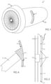
- a turbomachine 1 comprising a fan casing 2a and an internal casing 2b defining an internal space (also called “core” zone) in which the equipment of the turbomachine 1 is housed and in particular an oil reservoir 3.
- the tank 3 is housed in a space delimited externally by the internal casing 2b and internally by other elements of the turbomachine (not shown) such as for example a casing of a low pressure compressor.
- other elements of the turbomachine such as for example a casing of a low pressure compressor.
- the lower portion 6 and the upper portion 7 each represent a third of the total curved length of the enclosure 4.
- the control device 9 comprises a first sensor 10 positioned in the lower portion 6 to control the oil level there, and a second sensor 11 separate from the first sensor 10 and positioned in the upper portion 7 of the enclosure 4 to control the oil level there.
- the sensors 10, 11 are rectilinear sensors, simpler to manufacture than curved sensors, particularly in terms of manufacturing precision.
- the two sensors 10, 11 respectively have a length greater than the height of the lower portion 6 and the upper portion 7 of the tank 3.
- the first sensor 10 is positioned so as to cover the lower portion 6 and a part of the middle portion 8
- the second sensor 11 is positioned so as to cover the upper portion 7 and a part of the middle portion 8.
- the two sensors 10, 11 have a length substantially equal to half the total curved length of the enclosure 4.
- the oil level at any point in the tank 3.
- the Figures 2 and 3 are schematic and do not represent the lower, upper and middle portions 6, 7, 8 on a real scale.
- the two sensors 10, 11 respectively have a length less than the height of the lower portion 6 and the upper portion 7 of the tank 3.
- the first sensor 10 then only allows the oil level in the lower portion 6 of the tank to be monitored and the second sensor 11 then only allows the oil level in the upper portion 7 of the tank 3 to be controlled.
- the two sensors 10, 11 have a length slightly less than the height of the lower and upper portions 6, 7, that is to say slightly less than a third of the total curved length of the enclosure 4.
- the fixing of the first sensor 10 in the tank can be ensured either permanently, in which case it will not be possible to change the first sensor 10 in the event of failure (it will then be necessary to replace the entire tank 3), or removable.
- the tank comprises, on one of its walls, a sealing plug 12.
- the first sensor 10 can then be inserted and removed into or from the enclosure 4 through an opening 13 of the wall 5 which will be plugged by the sealing plug 12 once in place on wall 5.
- the first sensor 10 can be held in the enclosure 4 by stops (not shown).
- the senor can be secured to the sealing cap 12, as shown in the Figure 4 .
- the first sensor 10 When the first sensor 10 is removably attached, it is necessary to drain the reservoir (i.e. remove a certain amount of oil therefrom) to a level below the sealing plug 12 so that when the sealing plug 12 is opened, oil does not flow out of the reservoir through the opening 13.
- the fixing of the second sensor 11 in the tank 3 can be carried out in a known manner, that is to say by an access hatch (not shown) the second sensor 11 can then be removable.
- FIG. 5 schematically represents a particular type of sensor corresponding to the sensors 10, 11 used to control the oil level in the tank 3.
- This sensor comprises a float 14 which follows the oil level by being guided by rails 15 and comprises a magnetic element.
- an electromagnetic card 16 Opposite the float 14 is arranged an electromagnetic card 16 carrying contactors 17 which interact with the magnetic element of the float 14.
- the float 14 moves along the electromagnetic card 16 and the magnetic element acts with the contactors 17.
- the contactors 17 then move from an open position to a closed position, or vice versa, and an electrical signal circulates in the electromagnetic card 16 and is transmitted to an acquisition unit 18, remote from the tank 3, which transforms this electrical signal into information readable by a pilot or a mechanic.
- the transmission of the electrical signal is ensured by an electrical harness 19 associated with the first sensor 10 and an electrical harness 20 associated with the second sensor 11.
- the two electrical harnesses 19, 20 can join in a sheath 21.
- the float 14 of the second sensor 11 is in a high position and the electrical signal sent to the acquisition unit 18 is transformed into an alert signal for the pilot or the mechanic so that an intervention is carried out on the tank 3 and the excess oil is removed.
- the float 14 of the first sensor 10 When there is a lack of oil in the tank 3, the float 14 of the first sensor 10 is in a low position and the electrical signal sent to the acquisition unit 18 is transformed into an alert signal for the pilot or the mechanic so that an intervention is carried out on the tank 3 and oil is added to the tank 3.
- the float 14 of the first sensor 10 When the oil level in the tank 3 is at a correct level, the float 14 of the first sensor 10 is in a high position and the float 14 of the second sensor 11 is in an intermediate position or in a low position (in all cases, in a position away from its high position).
Landscapes
- Engineering & Computer Science (AREA)
- General Engineering & Computer Science (AREA)
- Mechanical Engineering (AREA)
- Chemical & Material Sciences (AREA)
- Combustion & Propulsion (AREA)
- Level Indicators Using A Float (AREA)
- Supply Devices, Intensifiers, Converters, And Telemotors (AREA)
Claims (6)
- Turbomaschine mit einem Öltank (3) für Turbomaschinen (1) und einer vom Tank beabstandeten Erfassungseinheit (18), wobei der Öltank enthält:- ein geschlossenes, kreisbogenförmiges Gehäuse (4), das zur Aufnahme von Öl geeignet ist, wobei das Gehäuse (4) einen unteren Abschnitt (6) und einen oberen Abschnitt (7) aufweist, die voneinander beabstandet sind, und- eine Vorrichtung (9) zur Kontrolle des Ölstands im Gehäuse (4),dadurch gekennzeichnet, dassdie Kontrollvorrichtung (9) einen ersten Sensor (10) umfasst,dadurch gekennzeichnet, dass der erste Sensor im unteren Abschnitt (6) des Gehäuses (4) positioniert ist, um den Ölstand darin zu kontrollieren, wobei die Vorrichtung einen zweiten Sensor (11) umfasst, der vom ersten Sensor (10) getrennt ist und im oberen Abschnitt (7) des Gehäuses (4) positioniert ist, um den Ölstand darin zu kontrollieren,wobei der erste Sensor (10) enthält:- ein erstes magnetisches Element,- einen ersten Schwimmer (14), der am ersten magnetischen Element befestigt ist,- erste Schienen (15), die dazu ausgelegt ist, den ersten Schwimmer (14) zu führen,- eine dem ersten Schwimmer (14) zugewandt angeordnete erste elektromagnetische Karte (16) mit ersten Kontaktgebern (17), die dazu ausgelegt sind, in Abhängigkeit von der Position des ersten magnetischen Elements von einer offenen Position in eine geschlossene Position zu schalten,- einen ersten Leitungsstrang (19), der die Übertragung des elektrischen Signals von der ersten elektromagnetischen Karte (16) an die Erfassungseinheit (18) sicherstellt,wobei der zweite Sensor (11) enthält:- ein zweites magnetisches Element,- einen zweiten Schwimmer (14), der an dem zweiten magnetischen Element befestigt ist,- zweite Schienen, die dazu ausgelegt sind, den zweiten Schwimmer (14) zu führen,- eine dem zweiten Schwimmer (14) zugewandt angeordnete zweite elektromagnetische Karte (16) mit zweiten Kontaktgebern (17), die dazu ausgelegt sind, in Abhängigkeit von der Position des zweiten magnetischen Elements von einer offenen Position in eine geschlossene Position zu schalten,- einen zweiten Leitungsstrang (20), der die Übertragung des elektrischen Signals von der zweiten elektromagnetischen Karte (16) an die Erfassungseinheit (18) sicherstellt.
- Turbomaschine nach Anspruch 1, wobeidas Gehäuse (4) einen Mittelabschnitt (8) enthält, der den unteren Abschnitt (6) vom oberen Abschnitt (7) trennt, und wobeider erste Sensor (10) so positioniert ist, dass er den unteren Abschnitt (6) und einen Teil des Mittelabschnitts (8) bedeckt, und der zweite Sensor (11) so positioniert ist, dass er den oberen Abschnitt (7) und einen Teil des Mittelabschnitts (8) bedeckt.
- Turbomaschine nach einem der vorangehenden Ansprüche, wobei
das Gehäuse (4) einen Verschlussstopfen enthält, der das Einsetzen bzw. Entfernen des ersten Sensors (10) gestattet. - Turbomaschine nach dem vorangehenden Anspruch, wobei
der erste Sensor (10) fest mit dem Verschlussstopfen (12) verbunden ist. - Turbomaschine nach einem der vorangehenden Ansprüche, wobei
der erste Sensor (10) und der zweite Sensor (11) geradlinig sind. - Turbomaschine nach einem der vorangehenden Ansprüche, wobei
der obere Abschnitt (7) und der untere Abschnitt (6) jeweils ein Drittel der gesamten Krümmungslänge des Gehäuses (4) ausmachen.
Applications Claiming Priority (1)
| Application Number | Priority Date | Filing Date | Title |
|---|---|---|---|
| FR1661593A FR3059361B1 (fr) | 2016-11-28 | 2016-11-28 | Reservoir d'huile comprenant un dispositif de controle du niveau d'huile |
Publications (3)
| Publication Number | Publication Date |
|---|---|
| EP3327260A1 EP3327260A1 (de) | 2018-05-30 |
| EP3327260B1 EP3327260B1 (de) | 2020-07-08 |
| EP3327260B2 true EP3327260B2 (de) | 2025-06-11 |
Family
ID=57755365
Family Applications (1)
| Application Number | Title | Priority Date | Filing Date |
|---|---|---|---|
| EP17203505.7A Active EP3327260B2 (de) | 2016-11-28 | 2017-11-24 | Öltank, der eine vorrichtung zur ölstandskontrolle umfasst |
Country Status (4)
| Country | Link |
|---|---|
| US (1) | US10683774B2 (de) |
| EP (1) | EP3327260B2 (de) |
| CN (1) | CN108119193B (de) |
| FR (1) | FR3059361B1 (de) |
Families Citing this family (5)
| Publication number | Priority date | Publication date | Assignee | Title |
|---|---|---|---|---|
| FR3059361B1 (fr) * | 2016-11-28 | 2018-12-07 | Safran Aircraft Engines | Reservoir d'huile comprenant un dispositif de controle du niveau d'huile |
| BE1026218B1 (fr) * | 2018-04-19 | 2019-11-21 | Safran Aero Boosters S.A. | Dispositif de mesure de niveau pour réservoir d'huile de turbomachine |
| FR3086325B1 (fr) | 2018-09-24 | 2020-11-20 | Safran Aircraft Engines | Reservoir auxiliaire d'huile pour une turbomachine d'aeronef |
| US12055430B2 (en) | 2022-11-21 | 2024-08-06 | Honeywell International Inc. | Fluid level sensor for a toroid-shaped tank |
| US12510002B2 (en) * | 2023-07-12 | 2025-12-30 | General Electric Company | Lubrication system for a turbine engine |
Family Cites Families (29)
| Publication number | Priority date | Publication date | Assignee | Title |
|---|---|---|---|---|
| FR96297E (fr) | 1967-11-24 | 1972-06-16 | Gen Electric | Détecteur de niveau de liquides. |
| US3741683A (en) * | 1971-07-02 | 1973-06-26 | Fmc Corp | Liquid level control system |
| DE2201910C3 (de) * | 1972-01-15 | 1974-10-03 | Daimler-Benz Ag, 7000 Stuttgart | Vorrichtung zur Niveau- und/oder Temperaturkontrolle von Flüssigkeiten |
| US4265262A (en) * | 1979-03-19 | 1981-05-05 | William Hotine | Fluent material level control system |
| US4745893A (en) * | 1986-12-03 | 1988-05-24 | Caterpillar Inc. | Digital oil level sensor |
| JP2731240B2 (ja) * | 1989-05-25 | 1998-03-25 | 富士重工業株式会社 | オイルセンサ |
| JPH05141217A (ja) * | 1991-11-14 | 1993-06-08 | Toyota Motor Corp | オイルレベルセンサ |
| CN2138289Y (zh) * | 1992-08-10 | 1993-07-14 | 张传新 | 浮磁式水位针 |
| US6584997B1 (en) * | 1998-03-30 | 2003-07-01 | Caterpillar Inc. | Overflow prevention mechanism for liquid transfer systems |
| US7216473B1 (en) * | 1999-07-09 | 2007-05-15 | Hamilton Sundstrand Corporation | Turbojet engine lubrication system |
| KR20020081624A (ko) * | 2001-04-19 | 2002-10-30 | 현대자동차주식회사 | 오일팬의 오일 보충장치 |
| US6776261B2 (en) * | 2002-05-29 | 2004-08-17 | Garlock Sealing Technologies Llc | Lubricant monitoring system |
| US6998552B1 (en) | 2005-07-27 | 2006-02-14 | Young-G Enterprise Corporation | Float-type liquid level switch assembly with light emitting elements |
| US8020665B2 (en) * | 2006-11-22 | 2011-09-20 | United Technologies Corporation | Lubrication system with extended emergency operability |
| US8215454B2 (en) * | 2006-11-22 | 2012-07-10 | United Technologies Corporation | Lubrication system with tolerance for reduced gravity |
| US8103462B2 (en) * | 2007-10-25 | 2012-01-24 | United Technologies Corporation | Oil consumption monitoring for aircraft engine |
| US8746410B1 (en) * | 2008-03-14 | 2014-06-10 | Raymond P. Lekowicz | Outdrive gear oil monitor |
| WO2009146308A1 (en) | 2008-05-29 | 2009-12-03 | Illinois Tool Works Inc. | Multi-level liquid level magnetic sensor |
| US8627667B2 (en) * | 2008-12-29 | 2014-01-14 | Roll-Royce Corporation | Gas turbine engine duct having a coupled fluid volume |
| FR2941744B1 (fr) * | 2009-01-30 | 2011-09-16 | Hispano Suiza Sa | Ensemble d'un boitier de relais d'accessoires et d'un reservoir d'huile |
| EP2573338B1 (de) * | 2011-09-20 | 2017-07-19 | Safran Aero Boosters SA | Überfüllungskontrolle eines Schmiersystems für einen Flugzeugmotor |
| US8985278B2 (en) * | 2012-09-07 | 2015-03-24 | United Technologies Corporation | Lubrication system having segmented anti-backflow feature |
| US20140076661A1 (en) * | 2012-09-19 | 2014-03-20 | United Technologies Corporation | Lubrication system having porous feature |
| FR3005486B1 (fr) * | 2013-05-07 | 2017-08-18 | Snecma | Lubrification dans une turbomachine |
| FR3010701B1 (fr) * | 2013-09-13 | 2015-10-09 | Snecma | Agencement d'un reservoir entre un capot de nacelle et une turbomachine |
| GB201419770D0 (en) * | 2014-11-06 | 2014-12-24 | Rolls Royce Plc | An oil distributor |
| CN205186537U (zh) * | 2015-10-23 | 2016-04-27 | 成都飞机工业(集团)有限责任公司 | 一种整体嵌入式滑油箱 |
| FR3059361B1 (fr) * | 2016-11-28 | 2018-12-07 | Safran Aircraft Engines | Reservoir d'huile comprenant un dispositif de controle du niveau d'huile |
| BE1025191B1 (fr) * | 2017-05-03 | 2018-12-06 | Safran Aero Boosters S.A. | Reservoir a sonde de niveau d’huile pour turbomachine |
-
2016
- 2016-11-28 FR FR1661593A patent/FR3059361B1/fr active Active
-
2017
- 2017-11-24 EP EP17203505.7A patent/EP3327260B2/de active Active
- 2017-11-27 US US15/822,812 patent/US10683774B2/en active Active
- 2017-11-28 CN CN201711210836.4A patent/CN108119193B/zh active Active
Also Published As
| Publication number | Publication date |
|---|---|
| EP3327260B1 (de) | 2020-07-08 |
| US20180156066A1 (en) | 2018-06-07 |
| FR3059361A1 (fr) | 2018-06-01 |
| EP3327260A1 (de) | 2018-05-30 |
| CN108119193A (zh) | 2018-06-05 |
| CN108119193B (zh) | 2022-03-18 |
| FR3059361B1 (fr) | 2018-12-07 |
| US10683774B2 (en) | 2020-06-16 |
Similar Documents
| Publication | Publication Date | Title |
|---|---|---|
| EP3327260B2 (de) | Öltank, der eine vorrichtung zur ölstandskontrolle umfasst | |
| EP2573338B1 (de) | Überfüllungskontrolle eines Schmiersystems für einen Flugzeugmotor | |
| EP2072762B1 (de) | Methode zur Verbrauchskontrolle und Aufdeckung von Leckagen in einem System zur Schmierung einer Strömungsmaschine | |
| EP2618039B1 (de) | Modulelement zur Verteilung von unter Druck stehendem Gas, und entsprechende Anlage | |
| FR3010701A1 (fr) | Agencement d'un reservoir entre un capot de nacelle et une turbomachine | |
| EP3149313B1 (de) | Verfahren und vorrichtung zur steuerung einer schubkraft eines strahltriebwerks | |
| EP3810510A1 (de) | Bordtank zur entwässerung eines flugzeugtriebwerks | |
| FR2829824A1 (fr) | Dispositif d'etancheite d'une cavite, notamment pour sonde de mesure d'incidence utilisee en aeronautique | |
| EP1132590A1 (de) | Thermostateinrichtung für zwei selektif gesteuerte Regelbereiche | |
| FR2895512A1 (fr) | Procede et dispositif de mesure automatique de la consommation en huile d'un moteur a combustion interne et de vidange dudit moteur | |
| EP3004700A1 (de) | System zur steuerung einer flüssigkeit in einem kreislauf | |
| EP3277992B1 (de) | Öldüse für turbinenmotor | |
| BE1012730A3 (fr) | Dispositif indicateur de niveau dans un reservoir de gaz de petrole liquefie. | |
| EP3587896B1 (de) | Gasversorgungsregler | |
| FR2984401A1 (fr) | Dispositif motorise comprenant un carter de lubrifiant | |
| US5190180A (en) | Reservoir fill tube with anti-leak valve | |
| EP3075973B1 (de) | Motor für generator oder motorpumpe, und entsprechender generator und entsprechende motorpumpe | |
| FR3129977A1 (fr) | Tronçon de ligne d’échappement | |
| FR3006409A1 (fr) | Systeme de regulation d'un liquide dans un circuit | |
| BE1025462B1 (fr) | Détermination d'un colmatage d'un filtre d'un système hydraulique | |
| EP3382399A1 (de) | Erfassungsvorrichtung für den durchfluss von fett, und entsprechendes schmiersystem | |
| WO2004005772A1 (fr) | Agencement d'un capteur et de ses connexions filaires dans un joint de culasse metallique, multifeuilles | |
| JPS61112712A (ja) | 潤滑油劣化検知装置 | |
| EP1143192A1 (de) | Uberdrucksicherheitsvorrichtung für Flüssiggastanks | |
| FR3103271A1 (fr) | Systeme de detection de pression dans une enceinte |
Legal Events
| Date | Code | Title | Description |
|---|---|---|---|
| PUAI | Public reference made under article 153(3) epc to a published international application that has entered the european phase |
Free format text: ORIGINAL CODE: 0009012 |
|
| STAA | Information on the status of an ep patent application or granted ep patent |
Free format text: STATUS: THE APPLICATION HAS BEEN PUBLISHED |
|
| AK | Designated contracting states |
Kind code of ref document: A1 Designated state(s): AL AT BE BG CH CY CZ DE DK EE ES FI FR GB GR HR HU IE IS IT LI LT LU LV MC MK MT NL NO PL PT RO RS SE SI SK SM TR |
|
| AX | Request for extension of the european patent |
Extension state: BA ME |
|
| STAA | Information on the status of an ep patent application or granted ep patent |
Free format text: STATUS: REQUEST FOR EXAMINATION WAS MADE |
|
| 17P | Request for examination filed |
Effective date: 20181119 |
|
| RBV | Designated contracting states (corrected) |
Designated state(s): AL AT BE BG CH CY CZ DE DK EE ES FI FR GB GR HR HU IE IS IT LI LT LU LV MC MK MT NL NO PL PT RO RS SE SI SK SM TR |
|
| STAA | Information on the status of an ep patent application or granted ep patent |
Free format text: STATUS: EXAMINATION IS IN PROGRESS |
|
| REG | Reference to a national code |
Ref country code: DE Ref legal event code: R079 Ref document number: 602017019304 Country of ref document: DE Free format text: PREVIOUS MAIN CLASS: F01D0025180000 Ipc: F01M0011120000 |
|
| GRAP | Despatch of communication of intention to grant a patent |
Free format text: ORIGINAL CODE: EPIDOSNIGR1 |
|
| STAA | Information on the status of an ep patent application or granted ep patent |
Free format text: STATUS: GRANT OF PATENT IS INTENDED |
|
| 17Q | First examination report despatched |
Effective date: 20200402 |
|
| RIC1 | Information provided on ipc code assigned before grant |
Ipc: F01M 11/12 20060101AFI20200409BHEP Ipc: F16N 19/00 20060101ALI20200409BHEP Ipc: F01D 25/20 20060101ALI20200409BHEP |
|
| INTG | Intention to grant announced |
Effective date: 20200506 |
|
| GRAS | Grant fee paid |
Free format text: ORIGINAL CODE: EPIDOSNIGR3 |
|
| GRAA | (expected) grant |
Free format text: ORIGINAL CODE: 0009210 |
|
| STAA | Information on the status of an ep patent application or granted ep patent |
Free format text: STATUS: THE PATENT HAS BEEN GRANTED |
|
| AK | Designated contracting states |
Kind code of ref document: B1 Designated state(s): AL AT BE BG CH CY CZ DE DK EE ES FI FR GB GR HR HU IE IS IT LI LT LU LV MC MK MT NL NO PL PT RO RS SE SI SK SM TR |
|
| REG | Reference to a national code |
Ref country code: CH Ref legal event code: EP Ref country code: AT Ref legal event code: REF Ref document number: 1288685 Country of ref document: AT Kind code of ref document: T Effective date: 20200715 |
|
| REG | Reference to a national code |
Ref country code: DE Ref legal event code: R096 Ref document number: 602017019304 Country of ref document: DE |
|
| REG | Reference to a national code |
Ref country code: IE Ref legal event code: FG4D Free format text: LANGUAGE OF EP DOCUMENT: FRENCH |
|
| REG | Reference to a national code |
Ref country code: SE Ref legal event code: TRGR |
|
| REG | Reference to a national code |
Ref country code: LT Ref legal event code: MG4D |
|
| REG | Reference to a national code |
Ref country code: AT Ref legal event code: MK05 Ref document number: 1288685 Country of ref document: AT Kind code of ref document: T Effective date: 20200708 |
|
| REG | Reference to a national code |
Ref country code: NL Ref legal event code: MP Effective date: 20200708 |
|
| PG25 | Lapsed in a contracting state [announced via postgrant information from national office to epo] |
Ref country code: ES Free format text: LAPSE BECAUSE OF FAILURE TO SUBMIT A TRANSLATION OF THE DESCRIPTION OR TO PAY THE FEE WITHIN THE PRESCRIBED TIME-LIMIT Effective date: 20200708 Ref country code: HR Free format text: LAPSE BECAUSE OF FAILURE TO SUBMIT A TRANSLATION OF THE DESCRIPTION OR TO PAY THE FEE WITHIN THE PRESCRIBED TIME-LIMIT Effective date: 20200708 Ref country code: LT Free format text: LAPSE BECAUSE OF FAILURE TO SUBMIT A TRANSLATION OF THE DESCRIPTION OR TO PAY THE FEE WITHIN THE PRESCRIBED TIME-LIMIT Effective date: 20200708 Ref country code: PT Free format text: LAPSE BECAUSE OF FAILURE TO SUBMIT A TRANSLATION OF THE DESCRIPTION OR TO PAY THE FEE WITHIN THE PRESCRIBED TIME-LIMIT Effective date: 20201109 Ref country code: FI Free format text: LAPSE BECAUSE OF FAILURE TO SUBMIT A TRANSLATION OF THE DESCRIPTION OR TO PAY THE FEE WITHIN THE PRESCRIBED TIME-LIMIT Effective date: 20200708 Ref country code: NO Free format text: LAPSE BECAUSE OF FAILURE TO SUBMIT A TRANSLATION OF THE DESCRIPTION OR TO PAY THE FEE WITHIN THE PRESCRIBED TIME-LIMIT Effective date: 20201008 Ref country code: GR Free format text: LAPSE BECAUSE OF FAILURE TO SUBMIT A TRANSLATION OF THE DESCRIPTION OR TO PAY THE FEE WITHIN THE PRESCRIBED TIME-LIMIT Effective date: 20201009 Ref country code: BG Free format text: LAPSE BECAUSE OF FAILURE TO SUBMIT A TRANSLATION OF THE DESCRIPTION OR TO PAY THE FEE WITHIN THE PRESCRIBED TIME-LIMIT Effective date: 20201008 Ref country code: AT Free format text: LAPSE BECAUSE OF FAILURE TO SUBMIT A TRANSLATION OF THE DESCRIPTION OR TO PAY THE FEE WITHIN THE PRESCRIBED TIME-LIMIT Effective date: 20200708 |
|
| PG25 | Lapsed in a contracting state [announced via postgrant information from national office to epo] |
Ref country code: RS Free format text: LAPSE BECAUSE OF FAILURE TO SUBMIT A TRANSLATION OF THE DESCRIPTION OR TO PAY THE FEE WITHIN THE PRESCRIBED TIME-LIMIT Effective date: 20200708 Ref country code: PL Free format text: LAPSE BECAUSE OF FAILURE TO SUBMIT A TRANSLATION OF THE DESCRIPTION OR TO PAY THE FEE WITHIN THE PRESCRIBED TIME-LIMIT Effective date: 20200708 Ref country code: LV Free format text: LAPSE BECAUSE OF FAILURE TO SUBMIT A TRANSLATION OF THE DESCRIPTION OR TO PAY THE FEE WITHIN THE PRESCRIBED TIME-LIMIT Effective date: 20200708 Ref country code: IS Free format text: LAPSE BECAUSE OF FAILURE TO SUBMIT A TRANSLATION OF THE DESCRIPTION OR TO PAY THE FEE WITHIN THE PRESCRIBED TIME-LIMIT Effective date: 20201108 |
|
| PG25 | Lapsed in a contracting state [announced via postgrant information from national office to epo] |
Ref country code: NL Free format text: LAPSE BECAUSE OF FAILURE TO SUBMIT A TRANSLATION OF THE DESCRIPTION OR TO PAY THE FEE WITHIN THE PRESCRIBED TIME-LIMIT Effective date: 20200708 |
|
| REG | Reference to a national code |
Ref country code: DE Ref legal event code: R026 Ref document number: 602017019304 Country of ref document: DE |
|
| PLBI | Opposition filed |
Free format text: ORIGINAL CODE: 0009260 |
|
| PLAX | Notice of opposition and request to file observation + time limit sent |
Free format text: ORIGINAL CODE: EPIDOSNOBS2 |
|
| PG25 | Lapsed in a contracting state [announced via postgrant information from national office to epo] |
Ref country code: DK Free format text: LAPSE BECAUSE OF FAILURE TO SUBMIT A TRANSLATION OF THE DESCRIPTION OR TO PAY THE FEE WITHIN THE PRESCRIBED TIME-LIMIT Effective date: 20200708 Ref country code: CZ Free format text: LAPSE BECAUSE OF FAILURE TO SUBMIT A TRANSLATION OF THE DESCRIPTION OR TO PAY THE FEE WITHIN THE PRESCRIBED TIME-LIMIT Effective date: 20200708 Ref country code: RO Free format text: LAPSE BECAUSE OF FAILURE TO SUBMIT A TRANSLATION OF THE DESCRIPTION OR TO PAY THE FEE WITHIN THE PRESCRIBED TIME-LIMIT Effective date: 20200708 Ref country code: EE Free format text: LAPSE BECAUSE OF FAILURE TO SUBMIT A TRANSLATION OF THE DESCRIPTION OR TO PAY THE FEE WITHIN THE PRESCRIBED TIME-LIMIT Effective date: 20200708 Ref country code: SM Free format text: LAPSE BECAUSE OF FAILURE TO SUBMIT A TRANSLATION OF THE DESCRIPTION OR TO PAY THE FEE WITHIN THE PRESCRIBED TIME-LIMIT Effective date: 20200708 |
|
| 26 | Opposition filed |
Opponent name: RAYTHEON TECHNOLOGIES CORPORATION Effective date: 20210408 |
|
| PG25 | Lapsed in a contracting state [announced via postgrant information from national office to epo] |
Ref country code: AL Free format text: LAPSE BECAUSE OF FAILURE TO SUBMIT A TRANSLATION OF THE DESCRIPTION OR TO PAY THE FEE WITHIN THE PRESCRIBED TIME-LIMIT Effective date: 20200708 |
|
| PG25 | Lapsed in a contracting state [announced via postgrant information from national office to epo] |
Ref country code: MC Free format text: LAPSE BECAUSE OF FAILURE TO SUBMIT A TRANSLATION OF THE DESCRIPTION OR TO PAY THE FEE WITHIN THE PRESCRIBED TIME-LIMIT Effective date: 20200708 Ref country code: SK Free format text: LAPSE BECAUSE OF FAILURE TO SUBMIT A TRANSLATION OF THE DESCRIPTION OR TO PAY THE FEE WITHIN THE PRESCRIBED TIME-LIMIT Effective date: 20200708 |
|
| REG | Reference to a national code |
Ref country code: CH Ref legal event code: PL |
|
| PG25 | Lapsed in a contracting state [announced via postgrant information from national office to epo] |
Ref country code: LU Free format text: LAPSE BECAUSE OF NON-PAYMENT OF DUE FEES Effective date: 20201124 |
|
| PLBB | Reply of patent proprietor to notice(s) of opposition received |
Free format text: ORIGINAL CODE: EPIDOSNOBS3 |
|
| REG | Reference to a national code |
Ref country code: BE Ref legal event code: MM Effective date: 20201130 |
|
| PG25 | Lapsed in a contracting state [announced via postgrant information from national office to epo] |
Ref country code: CH Free format text: LAPSE BECAUSE OF NON-PAYMENT OF DUE FEES Effective date: 20201130 Ref country code: LI Free format text: LAPSE BECAUSE OF NON-PAYMENT OF DUE FEES Effective date: 20201130 Ref country code: SI Free format text: LAPSE BECAUSE OF FAILURE TO SUBMIT A TRANSLATION OF THE DESCRIPTION OR TO PAY THE FEE WITHIN THE PRESCRIBED TIME-LIMIT Effective date: 20200708 |
|
| PG25 | Lapsed in a contracting state [announced via postgrant information from national office to epo] |
Ref country code: IE Free format text: LAPSE BECAUSE OF NON-PAYMENT OF DUE FEES Effective date: 20201124 |
|
| PG25 | Lapsed in a contracting state [announced via postgrant information from national office to epo] |
Ref country code: TR Free format text: LAPSE BECAUSE OF FAILURE TO SUBMIT A TRANSLATION OF THE DESCRIPTION OR TO PAY THE FEE WITHIN THE PRESCRIBED TIME-LIMIT Effective date: 20200708 Ref country code: MT Free format text: LAPSE BECAUSE OF FAILURE TO SUBMIT A TRANSLATION OF THE DESCRIPTION OR TO PAY THE FEE WITHIN THE PRESCRIBED TIME-LIMIT Effective date: 20200708 Ref country code: CY Free format text: LAPSE BECAUSE OF FAILURE TO SUBMIT A TRANSLATION OF THE DESCRIPTION OR TO PAY THE FEE WITHIN THE PRESCRIBED TIME-LIMIT Effective date: 20200708 |
|
| PG25 | Lapsed in a contracting state [announced via postgrant information from national office to epo] |
Ref country code: MK Free format text: LAPSE BECAUSE OF FAILURE TO SUBMIT A TRANSLATION OF THE DESCRIPTION OR TO PAY THE FEE WITHIN THE PRESCRIBED TIME-LIMIT Effective date: 20200708 |
|
| PG25 | Lapsed in a contracting state [announced via postgrant information from national office to epo] |
Ref country code: BE Free format text: LAPSE BECAUSE OF NON-PAYMENT OF DUE FEES Effective date: 20201130 |
|
| APBM | Appeal reference recorded |
Free format text: ORIGINAL CODE: EPIDOSNREFNO |
|
| APBP | Date of receipt of notice of appeal recorded |
Free format text: ORIGINAL CODE: EPIDOSNNOA2O |
|
| APAH | Appeal reference modified |
Free format text: ORIGINAL CODE: EPIDOSCREFNO |
|
| APBQ | Date of receipt of statement of grounds of appeal recorded |
Free format text: ORIGINAL CODE: EPIDOSNNOA3O |
|
| APAH | Appeal reference modified |
Free format text: ORIGINAL CODE: EPIDOSCREFNO |
|
| PLAB | Opposition data, opponent's data or that of the opponent's representative modified |
Free format text: ORIGINAL CODE: 0009299OPPO |
|
| R26 | Opposition filed (corrected) |
Opponent name: RTX CORPORATION Effective date: 20210408 |
|
| APBU | Appeal procedure closed |
Free format text: ORIGINAL CODE: EPIDOSNNOA9O |
|
| PGFP | Annual fee paid to national office [announced via postgrant information from national office to epo] |
Ref country code: SE Payment date: 20241022 Year of fee payment: 8 |
|
| PUAH | Patent maintained in amended form |
Free format text: ORIGINAL CODE: 0009272 |
|
| STAA | Information on the status of an ep patent application or granted ep patent |
Free format text: STATUS: PATENT MAINTAINED AS AMENDED |
|
| 27A | Patent maintained in amended form |
Effective date: 20250611 |
|
| AK | Designated contracting states |
Kind code of ref document: B2 Designated state(s): AL AT BE BG CH CY CZ DE DK EE ES FI FR GB GR HR HU IE IS IT LI LT LU LV MC MK MT NL NO PL PT RO RS SE SI SK SM TR |
|
| REG | Reference to a national code |
Ref country code: DE Ref legal event code: R102 Ref document number: 602017019304 Country of ref document: DE |
|
| REG | Reference to a national code |
Ref country code: SE Ref legal event code: RPEO |
|
| PGFP | Annual fee paid to national office [announced via postgrant information from national office to epo] |
Ref country code: DE Payment date: 20251118 Year of fee payment: 9 |
|
| PGFP | Annual fee paid to national office [announced via postgrant information from national office to epo] |
Ref country code: GB Payment date: 20251125 Year of fee payment: 9 |
|
| PGFP | Annual fee paid to national office [announced via postgrant information from national office to epo] |
Ref country code: IT Payment date: 20251128 Year of fee payment: 9 |
|
| PGFP | Annual fee paid to national office [announced via postgrant information from national office to epo] |
Ref country code: FR Payment date: 20251125 Year of fee payment: 9 |