EP3326563B1 - Double balloon catheter having a lobed inner balloon - Google Patents
Double balloon catheter having a lobed inner balloon Download PDFInfo
- Publication number
- EP3326563B1 EP3326563B1 EP17203142.9A EP17203142A EP3326563B1 EP 3326563 B1 EP3326563 B1 EP 3326563B1 EP 17203142 A EP17203142 A EP 17203142A EP 3326563 B1 EP3326563 B1 EP 3326563B1
- Authority
- EP
- European Patent Office
- Prior art keywords
- balloon
- medical apparatus
- distal end
- fluid
- contrast agent
- Prior art date
- Legal status (The legal status is an assumption and is not a legal conclusion. Google has not performed a legal analysis and makes no representation as to the accuracy of the status listed.)
- Active
Links
- 239000012530 fluid Substances 0.000 claims description 68
- 230000002262 irrigation Effects 0.000 claims description 53
- 238000003973 irrigation Methods 0.000 claims description 53
- 239000007921 spray Substances 0.000 claims description 32
- 238000003780 insertion Methods 0.000 claims description 27
- 230000037431 insertion Effects 0.000 claims description 27
- 239000002872 contrast media Substances 0.000 claims description 25
- 238000002594 fluoroscopy Methods 0.000 claims description 14
- 238000003384 imaging method Methods 0.000 claims description 7
- 239000012858 resilient material Substances 0.000 claims description 5
- 229910001285 shape-memory alloy Inorganic materials 0.000 claims description 4
- 238000000034 method Methods 0.000 description 33
- 210000001519 tissue Anatomy 0.000 description 31
- 238000002679 ablation Methods 0.000 description 28
- 239000000523 sample Substances 0.000 description 21
- 238000013153 catheter ablation Methods 0.000 description 3
- 210000005003 heart tissue Anatomy 0.000 description 3
- 229910001000 nickel titanium Inorganic materials 0.000 description 3
- 238000013021 overheating Methods 0.000 description 3
- 238000012800 visualization Methods 0.000 description 3
- FAPWRFPIFSIZLT-UHFFFAOYSA-M Sodium chloride Chemical compound [Na+].[Cl-] FAPWRFPIFSIZLT-UHFFFAOYSA-M 0.000 description 2
- 238000010586 diagram Methods 0.000 description 2
- 239000013013 elastic material Substances 0.000 description 2
- 230000006870 function Effects 0.000 description 2
- 238000002347 injection Methods 0.000 description 2
- 239000007924 injection Substances 0.000 description 2
- 239000000463 material Substances 0.000 description 2
- HLXZNVUGXRDIFK-UHFFFAOYSA-N nickel titanium Chemical compound [Ti].[Ti].[Ti].[Ti].[Ti].[Ti].[Ti].[Ti].[Ti].[Ti].[Ti].[Ni].[Ni].[Ni].[Ni].[Ni].[Ni].[Ni].[Ni].[Ni].[Ni].[Ni].[Ni].[Ni].[Ni] HLXZNVUGXRDIFK-UHFFFAOYSA-N 0.000 description 2
- 229920000139 polyethylene terephthalate Polymers 0.000 description 2
- 239000005020 polyethylene terephthalate Substances 0.000 description 2
- 229920000642 polymer Polymers 0.000 description 2
- 229920001296 polysiloxane Polymers 0.000 description 2
- 230000004044 response Effects 0.000 description 2
- 230000001225 therapeutic effect Effects 0.000 description 2
- 238000002560 therapeutic procedure Methods 0.000 description 2
- 206010003658 Atrial Fibrillation Diseases 0.000 description 1
- 241000272201 Columbiformes Species 0.000 description 1
- RYECOJGRJDOGPP-UHFFFAOYSA-N Ethylurea Chemical compound CCNC(N)=O RYECOJGRJDOGPP-UHFFFAOYSA-N 0.000 description 1
- 239000004677 Nylon Substances 0.000 description 1
- 229920002614 Polyether block amide Polymers 0.000 description 1
- 206010046996 Varicose vein Diseases 0.000 description 1
- HZEWFHLRYVTOIW-UHFFFAOYSA-N [Ti].[Ni] Chemical compound [Ti].[Ni] HZEWFHLRYVTOIW-UHFFFAOYSA-N 0.000 description 1
- 239000000853 adhesive Substances 0.000 description 1
- 230000001070 adhesive effect Effects 0.000 description 1
- 206010003119 arrhythmia Diseases 0.000 description 1
- 230000001419 dependent effect Effects 0.000 description 1
- 239000007933 dermal patch Substances 0.000 description 1
- 238000002059 diagnostic imaging Methods 0.000 description 1
- 229910003460 diamond Inorganic materials 0.000 description 1
- 239000010432 diamond Substances 0.000 description 1
- 239000007943 implant Substances 0.000 description 1
- 239000004973 liquid crystal related substance Substances 0.000 description 1
- 229910052751 metal Inorganic materials 0.000 description 1
- 239000002184 metal Substances 0.000 description 1
- 239000000203 mixture Substances 0.000 description 1
- 229920001778 nylon Polymers 0.000 description 1
- 230000003287 optical effect Effects 0.000 description 1
- 210000000056 organ Anatomy 0.000 description 1
- 230000035515 penetration Effects 0.000 description 1
- -1 polyethylene terephthalate Polymers 0.000 description 1
- 229920002635 polyurethane Polymers 0.000 description 1
- 239000004814 polyurethane Substances 0.000 description 1
- 238000004904 shortening Methods 0.000 description 1
- 239000011780 sodium chloride Substances 0.000 description 1
- 125000006850 spacer group Chemical group 0.000 description 1
- 230000000153 supplemental effect Effects 0.000 description 1
- 230000007704 transition Effects 0.000 description 1
- 208000027185 varicose disease Diseases 0.000 description 1
- 230000002792 vascular Effects 0.000 description 1
- 230000000007 visual effect Effects 0.000 description 1
Images


Classifications
-
- A—HUMAN NECESSITIES
- A61—MEDICAL OR VETERINARY SCIENCE; HYGIENE
- A61M—DEVICES FOR INTRODUCING MEDIA INTO, OR ONTO, THE BODY; DEVICES FOR TRANSDUCING BODY MEDIA OR FOR TAKING MEDIA FROM THE BODY; DEVICES FOR PRODUCING OR ENDING SLEEP OR STUPOR
- A61M25/00—Catheters; Hollow probes
- A61M25/10—Balloon catheters
- A61M25/1011—Multiple balloon catheters
-
- A—HUMAN NECESSITIES
- A61—MEDICAL OR VETERINARY SCIENCE; HYGIENE
- A61B—DIAGNOSIS; SURGERY; IDENTIFICATION
- A61B18/00—Surgical instruments, devices or methods for transferring non-mechanical forms of energy to or from the body
- A61B18/04—Surgical instruments, devices or methods for transferring non-mechanical forms of energy to or from the body by heating
- A61B18/12—Surgical instruments, devices or methods for transferring non-mechanical forms of energy to or from the body by heating by passing a current through the tissue to be heated, e.g. high-frequency current
- A61B18/14—Probes or electrodes therefor
- A61B18/1492—Probes or electrodes therefor having a flexible, catheter-like structure, e.g. for heart ablation
-
- A—HUMAN NECESSITIES
- A61—MEDICAL OR VETERINARY SCIENCE; HYGIENE
- A61B—DIAGNOSIS; SURGERY; IDENTIFICATION
- A61B6/00—Apparatus or devices for radiation diagnosis; Apparatus or devices for radiation diagnosis combined with radiation therapy equipment
- A61B6/48—Diagnostic techniques
- A61B6/481—Diagnostic techniques involving the use of contrast agents
-
- A—HUMAN NECESSITIES
- A61—MEDICAL OR VETERINARY SCIENCE; HYGIENE
- A61B—DIAGNOSIS; SURGERY; IDENTIFICATION
- A61B6/00—Apparatus or devices for radiation diagnosis; Apparatus or devices for radiation diagnosis combined with radiation therapy equipment
- A61B6/48—Diagnostic techniques
- A61B6/485—Diagnostic techniques involving fluorescence X-ray imaging
-
- A—HUMAN NECESSITIES
- A61—MEDICAL OR VETERINARY SCIENCE; HYGIENE
- A61M—DEVICES FOR INTRODUCING MEDIA INTO, OR ONTO, THE BODY; DEVICES FOR TRANSDUCING BODY MEDIA OR FOR TAKING MEDIA FROM THE BODY; DEVICES FOR PRODUCING OR ENDING SLEEP OR STUPOR
- A61M3/00—Medical syringes, e.g. enemata; Irrigators
- A61M3/02—Enemata; Irrigators
- A61M3/0279—Cannula; Nozzles; Tips; their connection means
-
- A—HUMAN NECESSITIES
- A61—MEDICAL OR VETERINARY SCIENCE; HYGIENE
- A61B—DIAGNOSIS; SURGERY; IDENTIFICATION
- A61B17/00—Surgical instruments, devices or methods, e.g. tourniquets
- A61B2017/00982—General structural features
- A61B2017/00991—Telescopic means
-
- A—HUMAN NECESSITIES
- A61—MEDICAL OR VETERINARY SCIENCE; HYGIENE
- A61B—DIAGNOSIS; SURGERY; IDENTIFICATION
- A61B17/00—Surgical instruments, devices or methods, e.g. tourniquets
- A61B17/22—Implements for squeezing-off ulcers or the like on the inside of inner organs of the body; Implements for scraping-out cavities of body organs, e.g. bones; Calculus removers; Calculus smashing apparatus; Apparatus for removing obstructions in blood vessels, not otherwise provided for
- A61B2017/22051—Implements for squeezing-off ulcers or the like on the inside of inner organs of the body; Implements for scraping-out cavities of body organs, e.g. bones; Calculus removers; Calculus smashing apparatus; Apparatus for removing obstructions in blood vessels, not otherwise provided for with an inflatable part, e.g. balloon, for positioning, blocking, or immobilisation
- A61B2017/22054—Implements for squeezing-off ulcers or the like on the inside of inner organs of the body; Implements for scraping-out cavities of body organs, e.g. bones; Calculus removers; Calculus smashing apparatus; Apparatus for removing obstructions in blood vessels, not otherwise provided for with an inflatable part, e.g. balloon, for positioning, blocking, or immobilisation with two balloons
-
- A—HUMAN NECESSITIES
- A61—MEDICAL OR VETERINARY SCIENCE; HYGIENE
- A61B—DIAGNOSIS; SURGERY; IDENTIFICATION
- A61B18/00—Surgical instruments, devices or methods for transferring non-mechanical forms of energy to or from the body
- A61B2018/00005—Cooling or heating of the probe or tissue immediately surrounding the probe
- A61B2018/00011—Cooling or heating of the probe or tissue immediately surrounding the probe with fluids
- A61B2018/00029—Cooling or heating of the probe or tissue immediately surrounding the probe with fluids open
-
- A—HUMAN NECESSITIES
- A61—MEDICAL OR VETERINARY SCIENCE; HYGIENE
- A61B—DIAGNOSIS; SURGERY; IDENTIFICATION
- A61B18/00—Surgical instruments, devices or methods for transferring non-mechanical forms of energy to or from the body
- A61B2018/00053—Mechanical features of the instrument of device
- A61B2018/00214—Expandable means emitting energy, e.g. by elements carried thereon
- A61B2018/0022—Balloons
- A61B2018/0025—Multiple balloons
- A61B2018/00255—Multiple balloons arranged one inside another
-
- A—HUMAN NECESSITIES
- A61—MEDICAL OR VETERINARY SCIENCE; HYGIENE
- A61B—DIAGNOSIS; SURGERY; IDENTIFICATION
- A61B18/00—Surgical instruments, devices or methods for transferring non-mechanical forms of energy to or from the body
- A61B2018/00315—Surgical instruments, devices or methods for transferring non-mechanical forms of energy to or from the body for treatment of particular body parts
- A61B2018/00345—Vascular system
- A61B2018/00351—Heart
- A61B2018/00357—Endocardium
-
- A—HUMAN NECESSITIES
- A61—MEDICAL OR VETERINARY SCIENCE; HYGIENE
- A61B—DIAGNOSIS; SURGERY; IDENTIFICATION
- A61B18/00—Surgical instruments, devices or methods for transferring non-mechanical forms of energy to or from the body
- A61B2018/00571—Surgical instruments, devices or methods for transferring non-mechanical forms of energy to or from the body for achieving a particular surgical effect
- A61B2018/00577—Ablation
-
- A—HUMAN NECESSITIES
- A61—MEDICAL OR VETERINARY SCIENCE; HYGIENE
- A61B—DIAGNOSIS; SURGERY; IDENTIFICATION
- A61B90/00—Instruments, implements or accessories specially adapted for surgery or diagnosis and not covered by any of the groups A61B1/00 - A61B50/00, e.g. for luxation treatment or for protecting wound edges
- A61B90/39—Markers, e.g. radio-opaque or breast lesions markers
- A61B2090/3933—Liquid markers
-
- A—HUMAN NECESSITIES
- A61—MEDICAL OR VETERINARY SCIENCE; HYGIENE
- A61B—DIAGNOSIS; SURGERY; IDENTIFICATION
- A61B90/00—Instruments, implements or accessories specially adapted for surgery or diagnosis and not covered by any of the groups A61B1/00 - A61B50/00, e.g. for luxation treatment or for protecting wound edges
- A61B90/39—Markers, e.g. radio-opaque or breast lesions markers
- A61B2090/3966—Radiopaque markers visible in an X-ray image
-
- A—HUMAN NECESSITIES
- A61—MEDICAL OR VETERINARY SCIENCE; HYGIENE
- A61M—DEVICES FOR INTRODUCING MEDIA INTO, OR ONTO, THE BODY; DEVICES FOR TRANSDUCING BODY MEDIA OR FOR TAKING MEDIA FROM THE BODY; DEVICES FOR PRODUCING OR ENDING SLEEP OR STUPOR
- A61M25/00—Catheters; Hollow probes
- A61M25/10—Balloon catheters
- A61M25/1011—Multiple balloon catheters
- A61M2025/1013—Multiple balloon catheters with concentrically mounted balloons, e.g. being independently inflatable
-
- A—HUMAN NECESSITIES
- A61—MEDICAL OR VETERINARY SCIENCE; HYGIENE
- A61M—DEVICES FOR INTRODUCING MEDIA INTO, OR ONTO, THE BODY; DEVICES FOR TRANSDUCING BODY MEDIA OR FOR TAKING MEDIA FROM THE BODY; DEVICES FOR PRODUCING OR ENDING SLEEP OR STUPOR
- A61M25/00—Catheters; Hollow probes
- A61M25/10—Balloon catheters
- A61M2025/1043—Balloon catheters with special features or adapted for special applications
- A61M2025/105—Balloon catheters with special features or adapted for special applications having a balloon suitable for drug delivery, e.g. by using holes for delivery, drug coating or membranes
-
- A—HUMAN NECESSITIES
- A61—MEDICAL OR VETERINARY SCIENCE; HYGIENE
- A61M—DEVICES FOR INTRODUCING MEDIA INTO, OR ONTO, THE BODY; DEVICES FOR TRANSDUCING BODY MEDIA OR FOR TAKING MEDIA FROM THE BODY; DEVICES FOR PRODUCING OR ENDING SLEEP OR STUPOR
- A61M25/00—Catheters; Hollow probes
- A61M25/10—Balloon catheters
- A61M2025/1043—Balloon catheters with special features or adapted for special applications
- A61M2025/1061—Balloon catheters with special features or adapted for special applications having separate inflations tubes, e.g. coaxial tubes or tubes otherwise arranged apart from the catheter tube
-
- A—HUMAN NECESSITIES
- A61—MEDICAL OR VETERINARY SCIENCE; HYGIENE
- A61M—DEVICES FOR INTRODUCING MEDIA INTO, OR ONTO, THE BODY; DEVICES FOR TRANSDUCING BODY MEDIA OR FOR TAKING MEDIA FROM THE BODY; DEVICES FOR PRODUCING OR ENDING SLEEP OR STUPOR
- A61M2205/00—General characteristics of the apparatus
- A61M2205/50—General characteristics of the apparatus with microprocessors or computers
- A61M2205/502—User interfaces, e.g. screens or keyboards
-
- A—HUMAN NECESSITIES
- A61—MEDICAL OR VETERINARY SCIENCE; HYGIENE
- A61M—DEVICES FOR INTRODUCING MEDIA INTO, OR ONTO, THE BODY; DEVICES FOR TRANSDUCING BODY MEDIA OR FOR TAKING MEDIA FROM THE BODY; DEVICES FOR PRODUCING OR ENDING SLEEP OR STUPOR
- A61M2205/00—General characteristics of the apparatus
- A61M2205/50—General characteristics of the apparatus with microprocessors or computers
- A61M2205/52—General characteristics of the apparatus with microprocessors or computers with memories providing a history of measured variating parameters of apparatus or patient
Definitions
- the present invention relates generally to invasive probes, and specifically to an invasive probe configured to irrigate tissue during a medical procedure.
- a wide range of medical procedures involve placing objects such as sensors, tubes, catheters, dispensing devices, and implants, within the body.
- An example of a medical procedure that is performed with a catheter is ablation of body tissue such as heart tissue.
- the ablation may be used to cure a variety of cardiac arrhythmia, as well as to manage atrial fibrillation.
- Such procedures are known in the art.
- Other medical procedures using ablation of body tissue, such as treating varicose veins, are also known in the art.
- the ablation energy for these procedures may be in the form of radio-frequency (RF) energy, which is supplied to the tissue via one or more electrodes of a catheter used for the procedures.
- RF radio-frequency
- US 2016/0317221 A1 discloses an applicator head for a tissue ablation device, the applicator head having an inner balloon and an outer balloon.
- EP 2 875 790 A2 discloses a catheter balloon assembly with one or more spacers positioned between the inner surface of an outer balloon member and the outer surface of an inner balloon member.
- a medical apparatus including a flexible insertion tube having a distal end for insertion into a body cavity, first and second conduits contained within the flexible insertion tube and configured to deliver first and second fluids, respectively, to the distal end, and a terminal member fixed to the distal end of the insertion tube and including a first balloon including one or more spray ports and coupled to the first conduit so that the first fluid inflates the first balloon and is delivered, via the one or more spray ports, to tissue in the body cavity, a second balloon contained within the first balloon and coupled to the second conduit so that the second fluid inflates the second balloon, and multiple splines including a flexible, resilient material and extending along a longitudinal axis of the terminal member, and configured to constrain the second balloon so that inflation of the second balloon creates lobes that form, along the longitudinal axis between the lobes, channels that direct the
- the first fluid includes an irrigation fluid
- the second fluid includes a contrast agent that can provide radiopacity for a fluoroscopy unit.
- the medical apparatus may include one or more electrodes mounted on the first balloon and configured to convey radio-frequency energy to tissue in a body cavity.
- the medical apparatus may include a telescoping shaft contained within the second balloon and configured to retract upon inflating the second balloon and to extend upon deflating the second balloon.
- the medical apparatus may include a flexible sleeve surrounding the telescoping shaft and configured to prevent the second fluid from entering the insertion tube.
- the splines have cross-sections selected from a group consisting of rectangular and elliptical cross-sections.
- the splines can be embedded in the second balloon.
- the splines can be affixed to an outer surface of the second balloon.
- the splines can be positioned within the second balloon.
- a method including inserting a distal end of flexible insertion tube into a body cavity, the flexible insertion tube containing first and second conduits configured to deliver first and second fluids, respectively, to a terminal member fixed to the distal end of the insertion tube, the terminal member including a first balloon including one or more spray ports and coupled to the first conduit, a second balloon contained within the first balloon and coupled to the second conduit, and multiple splines including a flexible, resilient material and extending along a longitudinal axis of the terminal member and configured to constrain the second balloon.
- the method also includes conveying, via the first conduit, the first fluid in order to inflate the first balloon and to deliver, via the one or more spray ports, the first fluid to tissue in the body cavity, and conveying, via the second conduit, the second fluid in order to inflate the second balloon and to create, using the splines, lobes on the second balloon that form, along the longitudinal axis between the lobes, channels that direct the first fluid from the first conduit to the one or more spray ports.
- a method including providing a medical probe for insertion into a body cavity, the medical probe including, at its distal end, an outer balloon including one or more spray ports and an inner balloon contained within the outer balloon, injecting a contrast agent into the inner balloon so as to inflate the inner balloon, visualizing the distal end of the medical probe in the body cavity by imaging the contrast agent in the inner balloon, thereby enabling the distal end to be maneuvered to a target location, and conveying, via the one or more spray ports in the outer balloon, irrigation fluid to tissue at the target location.
- the contrast agent provides radiopacity for a fluoroscopy unit
- visualizing the distal end may include capturing, by the fluoroscopy unit, an image of the contrast agent in the inner balloon, and presenting the image on a display.
- an apparatus including a medical apparatus of the present invention, and a control console configured: to inject a contrast agent into the inner balloon so as to inflate the inner balloon, to visualize the distal end of the medical apparatus in the body cavity by imaging the contrast agent in the inner balloon, thereby enabling the distal end to be maneuvered to a target location, and to convey, via the one or more spray ports in the outer balloon, irrigation fluid to tissue at the target location.
- a computer software product operated in conjunction with the medical apparatus of the present invention, the product including a non-transitory computer-readable medium, in which program instructions are stored, which instructions, when read by a computer connected to the medical apparatus and receiving signals therefrom, cause the computer, based on the received signals, upon injecting a contrast agent into the inner balloon in order to inflate the inner balloon, to visualize the distal end of the medical probe in the body cavity by imaging the contrast agent in the inner balloon, thereby enabling the distal end to be maneuvered to a target location while conveying, via the one or more spray ports in the outer balloon, irrigation fluid to tissue at the target location.
- Various therapeutic procedures such as cardiac ablation use an invasive medical probe such as a catheter that is inserted into a patient's body.
- an invasive medical probe such as a catheter that is inserted into a patient's body.
- the surface overheating may be manifested as charring, and the overheating of the underlying tissue may cause other damage to the tissue, even leading to penetration of the tissue.
- the region being ablated may be irrigated with an irrigation fluid, typically saline, in order to prevent charring.
- the medical probe also comprises a terminal member that is fixed to the distal end and comprises a first balloon (also referred to herein as an outer balloon), a second balloon (also referred to herein as an inner balloon) contained within the first balloon, and multiple splines that extend along a longitudinal axis of the terminal member.
- the first balloon comprises one or more irrigation spray ports and is coupled to the first conduit so that the first fluid inflates the first balloon, and is delivered, via the one or more spray ports, to tissue in the body cavity.
- the second balloon is coupled to the second conduit so that the second fluid received from the second conduit inflates the second balloon.
- the multiple splines comprise a shape-memory alloy and extend along a longitudinal axis of the terminal member, so that upon inflating the second balloon, the splines constrain the inflation of the second balloon in order to create lobes that form, along the longitudinal axis between the lobes, channels that direct the first fluid from the first conduit to the one or more spray ports.
- the first fluid may comprise an irrigation fluid.
- the inner balloon can control the overall volume (i.e., of both balloons). Additionally, as described hereinbelow, the inner balloon can be independently inflated or deflated, thereby significantly shortening the inflation/deflation time of the outer balloon, and reducing the stress on the outer balloon.
- the distal end of the medical probe upon injecting a fluoroscopic contrast agent into the inner balloon while inflating the inner balloon, can be visualized fluoroscopically in the body cavity by imaging the contrast medium in the inner balloon, thereby enabling the distal end to be maneuvered to a target location.
- the visualization of the distal end can be used by an operator while the medical probe conveys, via the one or more spray ports in the outer balloon, irrigation fluid to tissue at the target location.
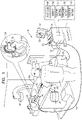
- Figure 1 is a schematic pictorial illustration of a medical system 20 comprising a medical probe 22 (e.g., a catheter) and a control console 24, and Figure 2 is a schematic illustration of a distal end 26 of the medical probe used in the medical system, in accordance with an embodiment of the present invention.
- System 20 may be based, for example, on the CARTO ® system, produced by Biosense Webster Inc. (Diamond Bar, California, U.S.A.).
- probe 22 is used for diagnostic or therapeutic treatment, such as performing ablation of heart tissue in a heart 28.
- probe 22 may be used, mutatis mutandis, for other therapeutic and/or diagnostic purposes in the heart or in other body organs.
- Probe 22 comprises an insertion tube 30, which an operator 32 inserts into a lumen, such as a chamber of heart 28, of a patient 34.
- operator 32 inserts insertion tube 30 through the vascular system of patient 34 so that a terminal member 36 fixed to distal end 26 enters a chamber of heart 28.
- Operator 32 can use a fluoroscopy unit 38 to visualize distal end 26 inside heart 28.
- Fluoroscopy unit 38 comprises an X-ray source 40, positioned above patient 34, which transmits X-rays through the patient.
- a flat panel detector 42 positioned below patient 34, comprises a scintillator layer 44 which converts the X-rays which pass through patient 34 into light, and a sensor layer 46 which converts the light into electrical signals.
- Sensor layer 46 typically comprises a two dimensional array of photodiodes, where each photodiode generates an electrical signal in proportion to the light detected by the photodiode.
- Control console 24 comprises a processor 48 that converts electrical signals from fluoroscopy unit 38 into an image 50, which the processor presents as information regarding the procedure on a display 52.
- Display 52 is assumed, by way of example, to comprise a cathode ray tube (CRT) display or a flat panel display such as a liquid crystal display (LCD), light emitting diode (LED) display or a plasma display.
- CTR cathode ray tube
- LCD liquid crystal display
- LED light emitting diode
- plasma display a plasma display.
- display 52 may comprise a touchscreen configured to accept inputs from operator 32, in addition to presenting image 50.
- console 24 is connected, via a cable 54, to body surface electrodes, which typically comprise adhesive skin patches 56 that are affixed to patient 34.
- Processor 48 determines position coordinates of distal end 26 inside heart 28 based on impedances measured between patches 56 and one or more electrodes 70 ( Figure 2 ) mounted on distal end 26.
- Other position tracking techniques may be used (e.g., magnetic-based sensors). Impedance-based position tracking techniques are described, for example, in U.S. Patents 5,983,126 , 6,456,864 and 5,944,022 .
- Magnetic position tracking techniques are described, for example, in U.S.
- the method of position sensing described hereinabove is implemented in the above-mentioned CARTO TM system and is described in detail in the patents cited above.
- Processor 48 typically comprises a general-purpose computer, with suitable front end and interface circuits for receiving signals from probe 22 and controlling the other components of console 24.
- Processor 48 may be programmed in software to carry out the functions that are described herein.
- the software may be downloaded to console 24 in electronic form, over a network, for example, or it may be provided on non-transitory tangible media, such as optical, magnetic or electronic memory media.
- some or all of the functions of processor 48 may be carried out by dedicated or programmable digital hardware components.
- processor 48 drives display 52 to update image 50 to present a current position of distal end 26 in the patient's body, as well as status information and guidance regarding the procedure that is in progress.
- Processor 48 stores data representing image 50 in a memory 58.
- operator 32 can manipulate image 50 using one or more input devices 60.
- display 52 comprises a touchscreen display
- operator 32 can manipulate image 50 via the touchscreen display.
- terminal member 36 comprises an inner balloon 62 that is contained within an outer balloon 64
- insertion tube 30 comprises an irrigation conduit 66 and an inflation conduit 68 that are contained within the insertion tube.
- Irrigation conduit 66 is coupled to outer balloon 64, and enables irrigation fluid to be injected into the outer balloon.
- Inflation conduit 68 is coupled to inner balloon 62, and enables a fluid separate from the irrigation fluid to be injected into the inner balloon.
- the fluid injected into the inner balloon may comprise a contrast-bearing fluid (also referred to herein as a contrast agent. Due to its configuration, medical probe 22 may also be referred to as a double balloon catheter.
- balloons 62 and 64 are inflated, and the outer balloon comprises electrodes 70 that typically comprise one or more thin metal layers formed over the outer balloon.
- terminal member 36 also comprises wires that convey radio-frequency energy from console 24 to electrodes 70, thermocouples that are configured to sense temperature, and position sensors that can aid navigation of distal end 26 in patient 34.
- Outer balloon 64 comprises irrigation spray ports 72 that are configured to convey irrigation fluid from within the outer balloon to tissue in a body cavity such as heart 26 (e.g., during an ablation procedure). While the configuration in Figure 2 shows irrigation spray ports 72 positioned within electrodes 72, positioning each of the irrigation points at any location on outer balloon 64 is considered to be within the spirit and scope of the present invention.
- the configuration of inner balloon 62 is described in the description referencing Figure 3 and 4 hereinbelow.
- Control console 24 also comprises an ablation module 74, an irrigation module 76 and an internal balloon inflation module 78 (also referred to herein as inflation module 78).
- ablation module 74 monitors and controls ablation parameters such as the level and the duration of ablation power applied to ablation electrodes 70.
- Irrigation module 76 delivers, via irrigation conduit 66, an irrigation fluid to outer balloon 64, and monitors the flow of the irrigation fluid to the outer balloon.
- the outer balloon conveys irrigation fluid to body cavity tissue via irrigation spray ports 72.
- Inflation module 78 is configured to deliver, via inflation conduit 68, an inflation fluid to inner balloon 62 in order to inflate the inner balloon.
- Inflation module 78 is also configured to extract the inflation fluid from the inner balloon in order to deflate inner balloon 62.
- the irrigation fluid is typically a saline solution that outer balloon delivers, via irrigation spray ports 72, to tissue in a body cavity during an ablation procedure in order to prevent charring.
- the inflation fluid comprises a contrast agent that can be used to enhance contrast of the inner balloon for medical imaging.
- the contrast agent may be configured to provide radiopacity for fluoroscopy unit 38.
- console 24 to present to operator 32, on display 52, inner balloon 62, while outer balloon 64 is performing an ablation procedure and conveying, via the one or more irrigation spray ports, irrigation fluid to tissue in heart 28.
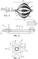
- Figure 3 is a schematic cross-sectional longitudinal view of terminal member 36 comprising inner balloon 62 and outer balloon 64 in extended (i.e., deflated) states
- Figure 4 is a schematic cross-sectional latitudinal view of terminal member 36 with the inner and the outer balloons in extended states in accordance with an embodiment of the present invention.
- electrodes 70 and irrigation spray ports 72 are not shown in Figures 3 and 4 .
- Inner balloon 62 typically comprises an elastic material such as silicone tubing or another polymer that is able to stretch while also having the ability to relax to its original (i.e., extended and non-inflated) tubular shape
- outer balloon 62 typically comprises materials such as Pellethane ® produced by the Lubrizol Corporation (Wickliffe, Ohio, U.S.A.), polyurethane, Pebax ® produced by Arkema S.A. (Colombes, France), nylon, polyethylene terephthalate (PET), or any blend or combination of these materials.
- the inflation of inner balloon 62 is constrained by a set of splines 82 that extend longitudinally about a telescoping shaft 84 that is enclosed within a thin flexible sleeve 90.
- Shaft 84 in turn extends along a longitudinal axis 86 of the terminal member.
- Telescoping shaft 84 typically comprises a concertina-like tube that enables the telescoping shaft to retract upon inflating the inner balloon and to extend upon deflating the inner balloon.
- inner balloon 62 is deflated, and splines 82 return to their respective original states.
- Splines 82 according to the invention have elliptical (e.g., circular) or rectangular (that may appear)
- telescoping shaft 84 is configured to retract, and splines 82 are configured to extend latitudinally in order to create lobes, as described hereinbelow in the description referencing Figure 6 .
- splines 82 return to their respective original (i.e., straightened) states, thereby extending telescoping shaft 84. While the example in Figure 3 (and in Figure 4 , as described hereinbelow) shows inner balloon 62 in an extended state comprising lobes 88, configuring the inner balloon to have no lobes while the inner balloon is in an extended state is considered to be within the spirit and scope of the present invention.
- Inner balloon 62 is typically more compliant than outer balloon 64, thereby enabling the inner balloon to transition from a "tube" shape when not inflated to a spherical shape comprising the lobes described hereinbelow in the description referencing Figure 6 .
- Sleeve 90 is typically made of silicone or a stretchable polymer that surrounds telescoping shaft 84 in order to act as a seal that prevents any back flow of inflation fluid from inner balloon 62 into the telescoping shaft and the bloodstream of the patient.
- Sleeve 90 stretches axially and relaxes as the nitinol wires shift the balloon from extended to inflated states.
- Figures 3 and 4 show terminal member 36 with inner balloon 64 in extended states.
- inner balloon 62 has an elliptical latitudinal cross-section
- outer balloon 64 comprises lobes 80 that given the outer balloon a "star shaped" latitudinal cross-section.
- inner balloon 62 upon inflating the inner and the outer balloons, inflates to have a star shaped latitudinal cross-section, and outer balloon 64 inflates to have an elliptical latitudinal cross-section.
- Figure 5 is a schematic cross-sectional longitudinal view of terminal member 36 comprising balloons 62 and 64 in inflated states, in accordance with an embodiment of the present invention.
- telescoping shaft 84 retracts longitudinally and splines 82 extend latitudinally upon inflating the balloons.
- Figure 6 is a schematic cross-sectional latitudinal view of terminal member 36 comprising the inner and the outer balloons in inflated states, in accordance with an embodiment of the present invention.
- inflation module 78 inflates inner balloon 62 by conveying an inflation fluid 100 to the inner balloon, splines 82 constrain the inflation of the inner balloon in order to create lobes 88 that form channels 102 (i.e., along longitudinal axis 86 between the lobes) that direct an irrigation fluid 104 from irrigation conduit 66 to irrigation spray ports 72.
- FIG. 7 is a schematic detail view showing outer balloon 64 in contact with endocardial tissue 110 of heart 28 during an ablation procedure
- Figure 8 is a schematic illustration showing a cut-away view of terminal member 36 during the ablation procedure, in accordance with an embodiment of the present invention.
- medical probe 22 can irrigate endocardial tissue 110 with irrigation fluid 104, exiting from irrigation spray ports 72, in order to cool the endocardial tissue and reduce charring.
- inner balloon 62 is inflated with inflation fluid 100 and outer balloon 64 is inflated with irrigation fluid 104.
- splines 82 extend from longitudinal axis 86 in order to create channels 102 (i.e., longitudinal depressions) on the surface of the inner balloon in order to direct the irrigation fluid to irrigation spray ports 72.
- Channels 102 are typically aligned with electrodes 70 in order to optimize flow of irrigation fluid 104 to irrigation spray ports 72. Additionally, channels 102 prevent the inner and the outer balloons from touching each other, which can block the delivery of the irrigation fluid to one or more of the irrigation spray ports.
- inflation module 78 can extract inflation fluid 100 from inner balloon 62 thereby deflating the inner balloon.
- Figure 9 is a flow diagram that illustrates a method of tracking terminal member 36 during an ablation procedure, in insertion with an embodiment of the present invention.
- operator 32 manipulates insertion tube 30 so that distal end 26 of medical probe 22 enters a chamber of heart 28, and in a first injection step 122, inflation module 78 injects inflation conduit 68 with inflation fluid 100 thereby inflating inner balloon 62.
- inflation fluid may comprise a contrast agent that provides radiopacity for fluoroscopy unit 38.
- processor 48 presents, in a visualization step 124, image 50 comprising a visualization of distal end 26.
- irrigation module 76 injects irrigation fluid 104 into insertion tube 30 in order to inflate outer balloon 64 and to convey, via channels 102 and irrigation spray ports 72, the irrigation fluid to the endocardial tissue.
- RF radio-frequency
- electrodes 72 perform an ablation procedure on endocardial tissue 110 while fluoroscopy unit images the contrast agent (i.e., inflation fluid 100) in the inner balloon and while irrigation spray ports 72 convey irrigation fluid 104 to the endocardial tissue.
- steps 122, 128 and 130 are typically performed in response to inputs from operator 32 (e.g., via input devices 60).
Landscapes
- Health & Medical Sciences (AREA)
- Life Sciences & Earth Sciences (AREA)
- Engineering & Computer Science (AREA)
- Heart & Thoracic Surgery (AREA)
- Medical Informatics (AREA)
- Biomedical Technology (AREA)
- Veterinary Medicine (AREA)
- Public Health (AREA)
- General Health & Medical Sciences (AREA)
- Animal Behavior & Ethology (AREA)
- Surgery (AREA)
- Nuclear Medicine, Radiotherapy & Molecular Imaging (AREA)
- Molecular Biology (AREA)
- Physics & Mathematics (AREA)
- Biophysics (AREA)
- Pathology (AREA)
- Optics & Photonics (AREA)
- High Energy & Nuclear Physics (AREA)
- Radiology & Medical Imaging (AREA)
- Anesthesiology (AREA)
- Hematology (AREA)
- Pulmonology (AREA)
- Child & Adolescent Psychology (AREA)
- Cardiology (AREA)
- Plasma & Fusion (AREA)
- Otolaryngology (AREA)
- Media Introduction/Drainage Providing Device (AREA)
- Surgical Instruments (AREA)
- Electrotherapy Devices (AREA)
Applications Claiming Priority (1)
| Application Number | Priority Date | Filing Date | Title |
|---|---|---|---|
| US15/360,967 US10821272B2 (en) | 2016-11-23 | 2016-11-23 | Double balloon catheter having a lobed inner balloon |
Publications (2)
| Publication Number | Publication Date |
|---|---|
| EP3326563A1 EP3326563A1 (en) | 2018-05-30 |
| EP3326563B1 true EP3326563B1 (en) | 2022-09-28 |
Family
ID=60450519
Family Applications (1)
| Application Number | Title | Priority Date | Filing Date |
|---|---|---|---|
| EP17203142.9A Active EP3326563B1 (en) | 2016-11-23 | 2017-11-22 | Double balloon catheter having a lobed inner balloon |
Country Status (7)
| Country | Link |
|---|---|
| US (2) | US10821272B2 (he) |
| EP (1) | EP3326563B1 (he) |
| JP (1) | JP6991840B2 (he) |
| CN (1) | CN108096685A (he) |
| AU (1) | AU2017248511A1 (he) |
| CA (1) | CA2985585A1 (he) |
| IL (2) | IL255115B (he) |
Families Citing this family (16)
| Publication number | Priority date | Publication date | Assignee | Title |
|---|---|---|---|---|
| US11400205B2 (en) | 2016-11-23 | 2022-08-02 | Biosense Webster (Israel) Ltd. | Balloon-in-balloon irrigation balloon catheter |
| US10821272B2 (en) * | 2016-11-23 | 2020-11-03 | Biosense Webster (Israel) Ltd. | Double balloon catheter having a lobed inner balloon |
| CN118044875A (zh) * | 2017-09-07 | 2024-05-17 | 波士顿科学医学有限公司 | 在较低消融压力下具有较大尺寸可调节性的冷冻球囊 |
| WO2019060833A1 (en) | 2017-09-25 | 2019-03-28 | Sirona Medical Technologies, Inc. | CATHETER AND METHOD FOR ENHANCED IRRIGATION |
| US20200205738A1 (en) * | 2018-12-31 | 2020-07-02 | Biosense Webster (Israel) Ltd. | Occlusion detection via fluid dilution |
| US12042216B2 (en) * | 2019-12-09 | 2024-07-23 | Biosense Webster (Israel) Ltd. | Irreversible-electroporation (IRE) balloon catheter with membrane-insulated high-voltage balloon wires |
| US20210177355A1 (en) * | 2019-12-11 | 2021-06-17 | Biosense Webster (Israel) Ltd. | Balloon Catheter with Position Sensors |
| USD944273S1 (en) * | 2020-09-08 | 2022-02-22 | Biosense Webster (Israel) Ltd. | Portion of a computer screen with a graphical user interface |
| USD944272S1 (en) * | 2020-09-08 | 2022-02-22 | Biosense Webster (Israel) Ltd. | Portion of a computer screen with a graphical user interface |
| US20220117656A1 (en) | 2020-10-15 | 2022-04-21 | Biosense Webster (Israel) Ltd. | Determining shape of expandable distal member of a catheter |
| CN114681766A (zh) * | 2020-12-30 | 2022-07-01 | 上海微创心通医疗科技有限公司 | 扩张球囊及球囊扩张导管 |
| US11957852B2 (en) * | 2021-01-14 | 2024-04-16 | Biosense Webster (Israel) Ltd. | Intravascular balloon with slidable central irrigation tube |
| US20220241009A1 (en) * | 2021-02-01 | 2022-08-04 | Medtronic, Inc. | Irrigation in association with pulsed electric field ablation |
| CN113134121B (zh) * | 2021-05-17 | 2023-02-07 | 浙江省嘉善县第一人民医院 | 一种感染性腔隙冲洗引流组件 |
| CN114305665A (zh) * | 2022-01-29 | 2022-04-12 | 上海睿刀医疗科技有限公司 | 分瓣囊状电极导管及包括该分瓣囊状电极导管的消融设备 |
| CN116965909B (zh) * | 2023-07-25 | 2024-04-30 | 苏州海宇新辰医疗科技有限公司 | 一种基于新型充气方式的冷冻消融用双层球囊导管 |
Family Cites Families (26)
| Publication number | Priority date | Publication date | Assignee | Title |
|---|---|---|---|---|
| US5766151A (en) * | 1991-07-16 | 1998-06-16 | Heartport, Inc. | Endovascular system for arresting the heart |
| US5391199A (en) | 1993-07-20 | 1995-02-21 | Biosense, Inc. | Apparatus and method for treating cardiac arrhythmias |
| US5558091A (en) | 1993-10-06 | 1996-09-24 | Biosense, Inc. | Magnetic determination of position and orientation |
| US5876336A (en) | 1994-10-11 | 1999-03-02 | Ep Technologies, Inc. | Systems and methods for guiding movable electrode elements within multiple-electrode structure |
| US6690963B2 (en) | 1995-01-24 | 2004-02-10 | Biosense, Inc. | System for determining the location and orientation of an invasive medical instrument |
| US5697377A (en) | 1995-11-22 | 1997-12-16 | Medtronic, Inc. | Catheter mapping system and method |
| US6177792B1 (en) | 1996-03-26 | 2001-01-23 | Bisense, Inc. | Mutual induction correction for radiator coils of an objects tracking system |
| US5944022A (en) | 1997-04-28 | 1999-08-31 | American Cardiac Ablation Co. Inc. | Catheter positioning system |
| US6251109B1 (en) * | 1997-06-27 | 2001-06-26 | Daig Corporation | Process and device for the treatment of atrial arrhythmia |
| US6172499B1 (en) | 1999-10-29 | 2001-01-09 | Ascension Technology Corporation | Eddy current error-reduced AC magnetic position measurement system |
| US6491711B1 (en) | 2000-11-14 | 2002-12-10 | Advanced Cardiovascular Systems, Inc. | Balloon catheter with non-circular balloon taper and method of use |
| US7727228B2 (en) | 2004-03-23 | 2010-06-01 | Medtronic Cryocath Lp | Method and apparatus for inflating and deflating balloon catheters |
| US8396548B2 (en) * | 2008-11-14 | 2013-03-12 | Vessix Vascular, Inc. | Selective drug delivery in a lumen |
| US8617149B2 (en) | 2006-10-02 | 2013-12-31 | Boston Scientific Scimed, Inc. | Common bond, double-balloon catheter |
| EP2334365B1 (en) * | 2008-09-22 | 2016-10-26 | Boston Scientific Scimed, Inc. | Biasing a catheter balloon |
| US8926602B2 (en) * | 2010-01-28 | 2015-01-06 | Medtronic Cryocath Lp | Triple balloon catheter |
| US9033965B2 (en) | 2010-02-01 | 2015-05-19 | Boston Scientific Scimed, Inc. | Nested balloon cryotherapy |
| US9199066B2 (en) * | 2010-03-12 | 2015-12-01 | Quattro Vascular Pte Ltd. | Device and method for compartmental vessel treatment |
| EP2872064A1 (en) * | 2012-07-13 | 2015-05-20 | Boston Scientific Scimed, Inc. | Off -wall electrode devices for nerve modulation |
| US9636172B2 (en) * | 2013-05-31 | 2017-05-02 | Medtronic Cryocath Lp | Compliant balloon with liquid injection |
| US10568686B2 (en) * | 2013-11-21 | 2020-02-25 | Biosense Webster (Israel) Ltd. | Multi-electrode balloon catheter with circumferential and point electrodes |
| US20160175041A1 (en) * | 2014-12-22 | 2016-06-23 | Biosense Webster (Israel) Ltd. | Balloon for ablation around pulmonary veins |
| EP3288478B1 (en) * | 2015-04-29 | 2019-12-25 | Innoblative Designs, Inc. | Cavitary tissue ablation |
| US9907610B2 (en) | 2015-05-07 | 2018-03-06 | Biosense Webster (Israel) Ltd. | Spring-loaded balloon |
| US10821272B2 (en) * | 2016-11-23 | 2020-11-03 | Biosense Webster (Israel) Ltd. | Double balloon catheter having a lobed inner balloon |
| US20190298441A1 (en) | 2018-03-28 | 2019-10-03 | Biosense Webster (Israel) Ltd. | Irrigated electrophysiology catheter with distinguishable electrodes for multi-electrode identification and orientation under 2-d visualization |
-
2016
- 2016-11-23 US US15/360,967 patent/US10821272B2/en active Active
-
2017
- 2017-10-18 IL IL255115A patent/IL255115B/he active IP Right Grant
- 2017-10-19 AU AU2017248511A patent/AU2017248511A1/en not_active Abandoned
- 2017-11-15 CA CA2985585A patent/CA2985585A1/en not_active Abandoned
- 2017-11-22 JP JP2017224330A patent/JP6991840B2/ja active Active
- 2017-11-22 EP EP17203142.9A patent/EP3326563B1/en active Active
- 2017-11-23 CN CN201711181811.6A patent/CN108096685A/zh active Pending
-
2020
- 2020-10-28 US US17/083,260 patent/US11813419B2/en active Active
-
2021
- 2021-03-18 IL IL281632A patent/IL281632B/he unknown
Also Published As
| Publication number | Publication date |
|---|---|
| AU2017248511A1 (en) | 2018-06-07 |
| CN108096685A (zh) | 2018-06-01 |
| IL255115B (he) | 2021-05-31 |
| US20180140807A1 (en) | 2018-05-24 |
| EP3326563A1 (en) | 2018-05-30 |
| IL281632A (he) | 2021-05-31 |
| US20210060313A1 (en) | 2021-03-04 |
| US10821272B2 (en) | 2020-11-03 |
| CA2985585A1 (en) | 2018-05-23 |
| JP2018083080A (ja) | 2018-05-31 |
| JP6991840B2 (ja) | 2022-01-13 |
| US11813419B2 (en) | 2023-11-14 |
| IL281632B (he) | 2022-06-01 |
| IL255115A0 (he) | 2017-12-31 |
Similar Documents
| Publication | Publication Date | Title |
|---|---|---|
| US11813419B2 (en) | Double balloon catheter having a lobed inner balloon | |
| CN106413610B (zh) | 形状变化的消融气囊 | |
| EP3381396A1 (en) | Balloon catheter with large area electrodes | |
| EP2632526B1 (en) | Catheter with coronary sinus ostium anchor | |
| CN106852708B (zh) | 具有基于光的接触传感器的消融导管 | |
| US20200390495A1 (en) | Directional balloon transseptal insertion device for medical procedures with improved transseptal puncture system with puncture member balloon seal | |
| US11666733B2 (en) | Directional balloon transseptal insertion device for medical procedures with improved handle | |
| US10342608B2 (en) | Ablation catheter system and method for deploying same | |
| CA3138742A1 (en) | Directional balloon transseptal insertion device for medical procedures | |
| AU2019284004A1 (en) | Sealed two-way magnetic manifold | |
| EP3231384A1 (en) | Pulmonary-vein cork device with ablation guiding trench | |
| JP7282883B2 (ja) | ガス方向制御を備えたクライオバルーン | |
| US10864354B2 (en) | Hydraulic auto crossing balloon/catheter | |
| EP3841998A1 (en) | Lasso catheter with balloon | |
| CN116744849A (zh) | 微导管 | |
| CN111374764A (zh) | 包括用于引导切穿心包的相机的心包导管 |
Legal Events
| Date | Code | Title | Description |
|---|---|---|---|
| PUAI | Public reference made under article 153(3) epc to a published international application that has entered the european phase |
Free format text: ORIGINAL CODE: 0009012 |
|
| STAA | Information on the status of an ep patent application or granted ep patent |
Free format text: STATUS: THE APPLICATION HAS BEEN PUBLISHED |
|
| AK | Designated contracting states |
Kind code of ref document: A1 Designated state(s): AL AT BE BG CH CY CZ DE DK EE ES FI FR GB GR HR HU IE IS IT LI LT LU LV MC MK MT NL NO PL PT RO RS SE SI SK SM TR |
|
| AX | Request for extension of the european patent |
Extension state: BA ME |
|
| STAA | Information on the status of an ep patent application or granted ep patent |
Free format text: STATUS: REQUEST FOR EXAMINATION WAS MADE |
|
| 17P | Request for examination filed |
Effective date: 20181130 |
|
| RBV | Designated contracting states (corrected) |
Designated state(s): AL AT BE BG CH CY CZ DE DK EE ES FI FR GB GR HR HU IE IS IT LI LT LU LV MC MK MT NL NO PL PT RO RS SE SI SK SM TR |
|
| STAA | Information on the status of an ep patent application or granted ep patent |
Free format text: STATUS: REQUEST FOR EXAMINATION WAS MADE |
|
| RIC1 | Information provided on ipc code assigned before grant |
Ipc: A61B 90/00 20160101ALN20211105BHEP Ipc: A61B 17/22 20060101ALI20211105BHEP Ipc: A61M 25/10 20130101ALI20211105BHEP Ipc: A61B 18/14 20060101AFI20211105BHEP |
|
| GRAP | Despatch of communication of intention to grant a patent |
Free format text: ORIGINAL CODE: EPIDOSNIGR1 |
|
| STAA | Information on the status of an ep patent application or granted ep patent |
Free format text: STATUS: GRANT OF PATENT IS INTENDED |
|
| INTG | Intention to grant announced |
Effective date: 20220105 |
|
| GRAJ | Information related to disapproval of communication of intention to grant by the applicant or resumption of examination proceedings by the epo deleted |
Free format text: ORIGINAL CODE: EPIDOSDIGR1 |
|
| STAA | Information on the status of an ep patent application or granted ep patent |
Free format text: STATUS: REQUEST FOR EXAMINATION WAS MADE |
|
| GRAP | Despatch of communication of intention to grant a patent |
Free format text: ORIGINAL CODE: EPIDOSNIGR1 |
|
| STAA | Information on the status of an ep patent application or granted ep patent |
Free format text: STATUS: GRANT OF PATENT IS INTENDED |
|
| INTC | Intention to grant announced (deleted) | ||
| RAP3 | Party data changed (applicant data changed or rights of an application transferred) |
Owner name: BIOSENSE WEBSTER (ISRAEL) LTD. |
|
| RIC1 | Information provided on ipc code assigned before grant |
Ipc: A61B 90/00 20160101ALN20220518BHEP Ipc: A61B 17/22 20060101ALI20220518BHEP Ipc: A61M 25/10 20130101ALI20220518BHEP Ipc: A61B 18/14 20060101AFI20220518BHEP |
|
| INTG | Intention to grant announced |
Effective date: 20220615 |
|
| GRAS | Grant fee paid |
Free format text: ORIGINAL CODE: EPIDOSNIGR3 |
|
| GRAA | (expected) grant |
Free format text: ORIGINAL CODE: 0009210 |
|
| STAA | Information on the status of an ep patent application or granted ep patent |
Free format text: STATUS: THE PATENT HAS BEEN GRANTED |
|
| AK | Designated contracting states |
Kind code of ref document: B1 Designated state(s): AL AT BE BG CH CY CZ DE DK EE ES FI FR GB GR HR HU IE IS IT LI LT LU LV MC MK MT NL NO PL PT RO RS SE SI SK SM TR |
|
| REG | Reference to a national code |
Ref country code: GB Ref legal event code: FG4D |
|
| REG | Reference to a national code |
Ref country code: CH Ref legal event code: EP |
|
| REG | Reference to a national code |
Ref country code: DE Ref legal event code: R096 Ref document number: 602017062102 Country of ref document: DE |
|
| REG | Reference to a national code |
Ref country code: AT Ref legal event code: REF Ref document number: 1520753 Country of ref document: AT Kind code of ref document: T Effective date: 20221015 |
|
| REG | Reference to a national code |
Ref country code: IE Ref legal event code: FG4D |
|
| REG | Reference to a national code |
Ref country code: NL Ref legal event code: FP |
|
| PGFP | Annual fee paid to national office [announced via postgrant information from national office to epo] |
Ref country code: NL Payment date: 20221019 Year of fee payment: 6 |
|
| REG | Reference to a national code |
Ref country code: LT Ref legal event code: MG9D |
|
| PG25 | Lapsed in a contracting state [announced via postgrant information from national office to epo] |
Ref country code: SE Free format text: LAPSE BECAUSE OF FAILURE TO SUBMIT A TRANSLATION OF THE DESCRIPTION OR TO PAY THE FEE WITHIN THE PRESCRIBED TIME-LIMIT Effective date: 20220928 Ref country code: RS Free format text: LAPSE BECAUSE OF FAILURE TO SUBMIT A TRANSLATION OF THE DESCRIPTION OR TO PAY THE FEE WITHIN THE PRESCRIBED TIME-LIMIT Effective date: 20220928 Ref country code: NO Free format text: LAPSE BECAUSE OF FAILURE TO SUBMIT A TRANSLATION OF THE DESCRIPTION OR TO PAY THE FEE WITHIN THE PRESCRIBED TIME-LIMIT Effective date: 20221228 Ref country code: LV Free format text: LAPSE BECAUSE OF FAILURE TO SUBMIT A TRANSLATION OF THE DESCRIPTION OR TO PAY THE FEE WITHIN THE PRESCRIBED TIME-LIMIT Effective date: 20220928 Ref country code: LT Free format text: LAPSE BECAUSE OF FAILURE TO SUBMIT A TRANSLATION OF THE DESCRIPTION OR TO PAY THE FEE WITHIN THE PRESCRIBED TIME-LIMIT Effective date: 20220928 Ref country code: FI Free format text: LAPSE BECAUSE OF FAILURE TO SUBMIT A TRANSLATION OF THE DESCRIPTION OR TO PAY THE FEE WITHIN THE PRESCRIBED TIME-LIMIT Effective date: 20220928 |
|
| REG | Reference to a national code |
Ref country code: AT Ref legal event code: MK05 Ref document number: 1520753 Country of ref document: AT Kind code of ref document: T Effective date: 20220928 |
|
| PG25 | Lapsed in a contracting state [announced via postgrant information from national office to epo] |
Ref country code: HR Free format text: LAPSE BECAUSE OF FAILURE TO SUBMIT A TRANSLATION OF THE DESCRIPTION OR TO PAY THE FEE WITHIN THE PRESCRIBED TIME-LIMIT Effective date: 20220928 Ref country code: GR Free format text: LAPSE BECAUSE OF FAILURE TO SUBMIT A TRANSLATION OF THE DESCRIPTION OR TO PAY THE FEE WITHIN THE PRESCRIBED TIME-LIMIT Effective date: 20221229 |
|
| PG25 | Lapsed in a contracting state [announced via postgrant information from national office to epo] |
Ref country code: SM Free format text: LAPSE BECAUSE OF FAILURE TO SUBMIT A TRANSLATION OF THE DESCRIPTION OR TO PAY THE FEE WITHIN THE PRESCRIBED TIME-LIMIT Effective date: 20220928 Ref country code: RO Free format text: LAPSE BECAUSE OF FAILURE TO SUBMIT A TRANSLATION OF THE DESCRIPTION OR TO PAY THE FEE WITHIN THE PRESCRIBED TIME-LIMIT Effective date: 20220928 Ref country code: PT Free format text: LAPSE BECAUSE OF FAILURE TO SUBMIT A TRANSLATION OF THE DESCRIPTION OR TO PAY THE FEE WITHIN THE PRESCRIBED TIME-LIMIT Effective date: 20230130 Ref country code: ES Free format text: LAPSE BECAUSE OF FAILURE TO SUBMIT A TRANSLATION OF THE DESCRIPTION OR TO PAY THE FEE WITHIN THE PRESCRIBED TIME-LIMIT Effective date: 20220928 Ref country code: CZ Free format text: LAPSE BECAUSE OF FAILURE TO SUBMIT A TRANSLATION OF THE DESCRIPTION OR TO PAY THE FEE WITHIN THE PRESCRIBED TIME-LIMIT Effective date: 20220928 Ref country code: AT Free format text: LAPSE BECAUSE OF FAILURE TO SUBMIT A TRANSLATION OF THE DESCRIPTION OR TO PAY THE FEE WITHIN THE PRESCRIBED TIME-LIMIT Effective date: 20220928 |
|
| PG25 | Lapsed in a contracting state [announced via postgrant information from national office to epo] |
Ref country code: SK Free format text: LAPSE BECAUSE OF FAILURE TO SUBMIT A TRANSLATION OF THE DESCRIPTION OR TO PAY THE FEE WITHIN THE PRESCRIBED TIME-LIMIT Effective date: 20220928 Ref country code: PL Free format text: LAPSE BECAUSE OF FAILURE TO SUBMIT A TRANSLATION OF THE DESCRIPTION OR TO PAY THE FEE WITHIN THE PRESCRIBED TIME-LIMIT Effective date: 20220928 Ref country code: IS Free format text: LAPSE BECAUSE OF FAILURE TO SUBMIT A TRANSLATION OF THE DESCRIPTION OR TO PAY THE FEE WITHIN THE PRESCRIBED TIME-LIMIT Effective date: 20230128 Ref country code: EE Free format text: LAPSE BECAUSE OF FAILURE TO SUBMIT A TRANSLATION OF THE DESCRIPTION OR TO PAY THE FEE WITHIN THE PRESCRIBED TIME-LIMIT Effective date: 20220928 |
|
| REG | Reference to a national code |
Ref country code: DE Ref legal event code: R097 Ref document number: 602017062102 Country of ref document: DE |
|
| PG25 | Lapsed in a contracting state [announced via postgrant information from national office to epo] |
Ref country code: MC Free format text: LAPSE BECAUSE OF FAILURE TO SUBMIT A TRANSLATION OF THE DESCRIPTION OR TO PAY THE FEE WITHIN THE PRESCRIBED TIME-LIMIT Effective date: 20220928 Ref country code: AL Free format text: LAPSE BECAUSE OF FAILURE TO SUBMIT A TRANSLATION OF THE DESCRIPTION OR TO PAY THE FEE WITHIN THE PRESCRIBED TIME-LIMIT Effective date: 20220928 |
|
| REG | Reference to a national code |
Ref country code: CH Ref legal event code: PL |
|
| REG | Reference to a national code |
Ref country code: BE Ref legal event code: MM Effective date: 20221130 |
|
| PG25 | Lapsed in a contracting state [announced via postgrant information from national office to epo] |
Ref country code: LI Free format text: LAPSE BECAUSE OF NON-PAYMENT OF DUE FEES Effective date: 20221130 Ref country code: DK Free format text: LAPSE BECAUSE OF FAILURE TO SUBMIT A TRANSLATION OF THE DESCRIPTION OR TO PAY THE FEE WITHIN THE PRESCRIBED TIME-LIMIT Effective date: 20220928 Ref country code: CH Free format text: LAPSE BECAUSE OF NON-PAYMENT OF DUE FEES Effective date: 20221130 |
|
| PLBE | No opposition filed within time limit |
Free format text: ORIGINAL CODE: 0009261 |
|
| STAA | Information on the status of an ep patent application or granted ep patent |
Free format text: STATUS: NO OPPOSITION FILED WITHIN TIME LIMIT |
|
| PG25 | Lapsed in a contracting state [announced via postgrant information from national office to epo] |
Ref country code: LU Free format text: LAPSE BECAUSE OF NON-PAYMENT OF DUE FEES Effective date: 20221122 |
|
| 26N | No opposition filed |
Effective date: 20230629 |
|
| PG25 | Lapsed in a contracting state [announced via postgrant information from national office to epo] |
Ref country code: IE Free format text: LAPSE BECAUSE OF NON-PAYMENT OF DUE FEES Effective date: 20221122 |
|
| PGFP | Annual fee paid to national office [announced via postgrant information from national office to epo] |
Ref country code: GB Payment date: 20230928 Year of fee payment: 7 |
|
| PG25 | Lapsed in a contracting state [announced via postgrant information from national office to epo] |
Ref country code: SI Free format text: LAPSE BECAUSE OF FAILURE TO SUBMIT A TRANSLATION OF THE DESCRIPTION OR TO PAY THE FEE WITHIN THE PRESCRIBED TIME-LIMIT Effective date: 20220928 Ref country code: BE Free format text: LAPSE BECAUSE OF NON-PAYMENT OF DUE FEES Effective date: 20221130 |
|
| PGFP | Annual fee paid to national office [announced via postgrant information from national office to epo] |
Ref country code: FR Payment date: 20230929 Year of fee payment: 7 |
|
| PGFP | Annual fee paid to national office [announced via postgrant information from national office to epo] |
Ref country code: IT Payment date: 20231010 Year of fee payment: 7 Ref country code: DE Payment date: 20230929 Year of fee payment: 7 |
|
| PG25 | Lapsed in a contracting state [announced via postgrant information from national office to epo] |
Ref country code: HU Free format text: LAPSE BECAUSE OF FAILURE TO SUBMIT A TRANSLATION OF THE DESCRIPTION OR TO PAY THE FEE WITHIN THE PRESCRIBED TIME-LIMIT; INVALID AB INITIO Effective date: 20171122 |
|
| PG25 | Lapsed in a contracting state [announced via postgrant information from national office to epo] |
Ref country code: CY Free format text: LAPSE BECAUSE OF FAILURE TO SUBMIT A TRANSLATION OF THE DESCRIPTION OR TO PAY THE FEE WITHIN THE PRESCRIBED TIME-LIMIT Effective date: 20220928 |
|
| PG25 | Lapsed in a contracting state [announced via postgrant information from national office to epo] |
Ref country code: MK Free format text: LAPSE BECAUSE OF FAILURE TO SUBMIT A TRANSLATION OF THE DESCRIPTION OR TO PAY THE FEE WITHIN THE PRESCRIBED TIME-LIMIT Effective date: 20220928 |
|
| PG25 | Lapsed in a contracting state [announced via postgrant information from national office to epo] |
Ref country code: TR Free format text: LAPSE BECAUSE OF FAILURE TO SUBMIT A TRANSLATION OF THE DESCRIPTION OR TO PAY THE FEE WITHIN THE PRESCRIBED TIME-LIMIT Effective date: 20220928 |
|
| REG | Reference to a national code |
Ref country code: NL Ref legal event code: MM Effective date: 20231201 |
|
| PG25 | Lapsed in a contracting state [announced via postgrant information from national office to epo] |
Ref country code: BG Free format text: LAPSE BECAUSE OF FAILURE TO SUBMIT A TRANSLATION OF THE DESCRIPTION OR TO PAY THE FEE WITHIN THE PRESCRIBED TIME-LIMIT Effective date: 20220928 |
|
| PG25 | Lapsed in a contracting state [announced via postgrant information from national office to epo] |
Ref country code: NL Free format text: LAPSE BECAUSE OF NON-PAYMENT OF DUE FEES Effective date: 20231201 |