EP2334365B1 - Biasing a catheter balloon - Google Patents
Biasing a catheter balloon Download PDFInfo
- Publication number
- EP2334365B1 EP2334365B1 EP09792702.4A EP09792702A EP2334365B1 EP 2334365 B1 EP2334365 B1 EP 2334365B1 EP 09792702 A EP09792702 A EP 09792702A EP 2334365 B1 EP2334365 B1 EP 2334365B1
- Authority
- EP
- European Patent Office
- Prior art keywords
- balloon
- catheter
- spring member
- elongate member
- catheter shaft
- Prior art date
- Legal status (The legal status is an assumption and is not a legal conclusion. Google has not performed a legal analysis and makes no representation as to the accuracy of the status listed.)
- Active
Links
- 238000000034 method Methods 0.000 claims description 22
- 239000000463 material Substances 0.000 claims description 13
- 239000007788 liquid Substances 0.000 claims description 12
- 230000008878 coupling Effects 0.000 claims description 10
- 238000010168 coupling process Methods 0.000 claims description 10
- 238000005859 coupling reaction Methods 0.000 claims description 10
- 238000000315 cryotherapy Methods 0.000 claims description 10
- 238000002560 therapeutic procedure Methods 0.000 description 8
- 210000003492 pulmonary vein Anatomy 0.000 description 5
- 206010003658 Atrial Fibrillation Diseases 0.000 description 4
- 230000006835 compression Effects 0.000 description 4
- 238000007906 compression Methods 0.000 description 4
- 230000008859 change Effects 0.000 description 3
- 238000002399 angioplasty Methods 0.000 description 2
- 230000008901 benefit Effects 0.000 description 2
- 210000004204 blood vessel Anatomy 0.000 description 2
- 238000010276 construction Methods 0.000 description 2
- 230000000694 effects Effects 0.000 description 2
- 239000012530 fluid Substances 0.000 description 2
- 239000002184 metal Substances 0.000 description 2
- 230000004048 modification Effects 0.000 description 2
- 238000012986 modification Methods 0.000 description 2
- 210000005166 vasculature Anatomy 0.000 description 2
- 229910000831 Steel Inorganic materials 0.000 description 1
- 238000002679 ablation Methods 0.000 description 1
- 230000009471 action Effects 0.000 description 1
- 210000001124 body fluid Anatomy 0.000 description 1
- 239000010839 body fluid Substances 0.000 description 1
- 238000009954 braiding Methods 0.000 description 1
- 238000001816 cooling Methods 0.000 description 1
- 210000001105 femoral artery Anatomy 0.000 description 1
- 238000007710 freezing Methods 0.000 description 1
- 230000008014 freezing Effects 0.000 description 1
- 230000003993 interaction Effects 0.000 description 1
- 210000005246 left atrium Anatomy 0.000 description 1
- 210000000056 organ Anatomy 0.000 description 1
- 230000037361 pathway Effects 0.000 description 1
- 230000004044 response Effects 0.000 description 1
- 239000010959 steel Substances 0.000 description 1
- 230000002792 vascular Effects 0.000 description 1
Images


Classifications
-
- A—HUMAN NECESSITIES
- A61—MEDICAL OR VETERINARY SCIENCE; HYGIENE
- A61M—DEVICES FOR INTRODUCING MEDIA INTO, OR ONTO, THE BODY; DEVICES FOR TRANSDUCING BODY MEDIA OR FOR TAKING MEDIA FROM THE BODY; DEVICES FOR PRODUCING OR ENDING SLEEP OR STUPOR
- A61M25/00—Catheters; Hollow probes
- A61M25/10—Balloon catheters
- A61M25/1006—Balloons formed between concentric tubes
-
- A—HUMAN NECESSITIES
- A61—MEDICAL OR VETERINARY SCIENCE; HYGIENE
- A61M—DEVICES FOR INTRODUCING MEDIA INTO, OR ONTO, THE BODY; DEVICES FOR TRANSDUCING BODY MEDIA OR FOR TAKING MEDIA FROM THE BODY; DEVICES FOR PRODUCING OR ENDING SLEEP OR STUPOR
- A61M25/00—Catheters; Hollow probes
- A61M25/10—Balloon catheters
-
- A—HUMAN NECESSITIES
- A61—MEDICAL OR VETERINARY SCIENCE; HYGIENE
- A61M—DEVICES FOR INTRODUCING MEDIA INTO, OR ONTO, THE BODY; DEVICES FOR TRANSDUCING BODY MEDIA OR FOR TAKING MEDIA FROM THE BODY; DEVICES FOR PRODUCING OR ENDING SLEEP OR STUPOR
- A61M25/00—Catheters; Hollow probes
- A61M25/01—Introducing, guiding, advancing, emplacing or holding catheters
- A61M25/09—Guide wires
-
- A—HUMAN NECESSITIES
- A61—MEDICAL OR VETERINARY SCIENCE; HYGIENE
- A61M—DEVICES FOR INTRODUCING MEDIA INTO, OR ONTO, THE BODY; DEVICES FOR TRANSDUCING BODY MEDIA OR FOR TAKING MEDIA FROM THE BODY; DEVICES FOR PRODUCING OR ENDING SLEEP OR STUPOR
- A61M29/00—Dilators with or without means for introducing media, e.g. remedies
- A61M29/02—Dilators made of swellable material
-
- A—HUMAN NECESSITIES
- A61—MEDICAL OR VETERINARY SCIENCE; HYGIENE
- A61M—DEVICES FOR INTRODUCING MEDIA INTO, OR ONTO, THE BODY; DEVICES FOR TRANSDUCING BODY MEDIA OR FOR TAKING MEDIA FROM THE BODY; DEVICES FOR PRODUCING OR ENDING SLEEP OR STUPOR
- A61M25/00—Catheters; Hollow probes
- A61M2025/0004—Catheters; Hollow probes having two or more concentrically arranged tubes for forming a concentric catheter system
-
- A—HUMAN NECESSITIES
- A61—MEDICAL OR VETERINARY SCIENCE; HYGIENE
- A61M—DEVICES FOR INTRODUCING MEDIA INTO, OR ONTO, THE BODY; DEVICES FOR TRANSDUCING BODY MEDIA OR FOR TAKING MEDIA FROM THE BODY; DEVICES FOR PRODUCING OR ENDING SLEEP OR STUPOR
- A61M25/00—Catheters; Hollow probes
- A61M25/01—Introducing, guiding, advancing, emplacing or holding catheters
- A61M25/06—Body-piercing guide needles or the like
- A61M25/0662—Guide tubes
- A61M2025/0681—Systems with catheter and outer tubing, e.g. sheath, sleeve or guide tube
-
- A—HUMAN NECESSITIES
- A61—MEDICAL OR VETERINARY SCIENCE; HYGIENE
- A61M—DEVICES FOR INTRODUCING MEDIA INTO, OR ONTO, THE BODY; DEVICES FOR TRANSDUCING BODY MEDIA OR FOR TAKING MEDIA FROM THE BODY; DEVICES FOR PRODUCING OR ENDING SLEEP OR STUPOR
- A61M25/00—Catheters; Hollow probes
- A61M25/10—Balloon catheters
- A61M25/1011—Multiple balloon catheters
- A61M2025/1013—Multiple balloon catheters with concentrically mounted balloons, e.g. being independently inflatable
-
- A—HUMAN NECESSITIES
- A61—MEDICAL OR VETERINARY SCIENCE; HYGIENE
- A61M—DEVICES FOR INTRODUCING MEDIA INTO, OR ONTO, THE BODY; DEVICES FOR TRANSDUCING BODY MEDIA OR FOR TAKING MEDIA FROM THE BODY; DEVICES FOR PRODUCING OR ENDING SLEEP OR STUPOR
- A61M25/00—Catheters; Hollow probes
- A61M25/10—Balloon catheters
- A61M2025/1043—Balloon catheters with special features or adapted for special applications
- A61M2025/1061—Balloon catheters with special features or adapted for special applications having separate inflations tubes, e.g. coaxial tubes or tubes otherwise arranged apart from the catheter tube
-
- A—HUMAN NECESSITIES
- A61—MEDICAL OR VETERINARY SCIENCE; HYGIENE
- A61M—DEVICES FOR INTRODUCING MEDIA INTO, OR ONTO, THE BODY; DEVICES FOR TRANSDUCING BODY MEDIA OR FOR TAKING MEDIA FROM THE BODY; DEVICES FOR PRODUCING OR ENDING SLEEP OR STUPOR
- A61M25/00—Catheters; Hollow probes
- A61M25/10—Balloon catheters
- A61M2025/1043—Balloon catheters with special features or adapted for special applications
- A61M2025/1068—Balloon catheters with special features or adapted for special applications having means for varying the length or diameter of the deployed balloon, this variations could be caused by excess pressure
-
- A—HUMAN NECESSITIES
- A61—MEDICAL OR VETERINARY SCIENCE; HYGIENE
- A61M—DEVICES FOR INTRODUCING MEDIA INTO, OR ONTO, THE BODY; DEVICES FOR TRANSDUCING BODY MEDIA OR FOR TAKING MEDIA FROM THE BODY; DEVICES FOR PRODUCING OR ENDING SLEEP OR STUPOR
- A61M25/00—Catheters; Hollow probes
- A61M25/10—Balloon catheters
- A61M2025/1043—Balloon catheters with special features or adapted for special applications
- A61M2025/1077—Balloon catheters with special features or adapted for special applications having a system for expelling the air out of the balloon before inflation and use
-
- A—HUMAN NECESSITIES
- A61—MEDICAL OR VETERINARY SCIENCE; HYGIENE
- A61M—DEVICES FOR INTRODUCING MEDIA INTO, OR ONTO, THE BODY; DEVICES FOR TRANSDUCING BODY MEDIA OR FOR TAKING MEDIA FROM THE BODY; DEVICES FOR PRODUCING OR ENDING SLEEP OR STUPOR
- A61M25/00—Catheters; Hollow probes
- A61M25/10—Balloon catheters
- A61M2025/1043—Balloon catheters with special features or adapted for special applications
- A61M2025/1081—Balloon catheters with special features or adapted for special applications having sheaths or the like for covering the balloon but not forming a permanent part of the balloon, e.g. retractable, dissolvable or tearable sheaths
Definitions
- a number of medical conditions may be treated in a minimally invasive manner with various kinds of catheters designed to reach treatment sites internal to a patient's body.
- Balloon catheters in particular, may be employed, for example, in angioplasty procedures, to widen obstructed blood vessels and optionally deliver stents; or in procedures to treat atrial fibrillation, such as by electrically isolating a patient's pulmonary veins.
- expansion of the balloon at the treatment site provides the desired therapy, such as expanding an obstructed blood vessel during an angioplasty procedure.
- an energy source within the balloon delivers the desired therapy, and the balloon serves to either position the energy source or communicate energy from or to tissue being treated.
- a balloon catheter in procedures for treating atrial fibrillation by electrically isolating pulmonary veins, can be used to position a radio frequency energy source in proximity to the pulmonary vein tissue to be treated; similarly, in cryoablation procedures for treating the same condition, a cryotherapy balloon catheter can be used to extract heat, through the surface of the balloon, from the pulmonary vein tissue.
- WO 2008/000066 provides a medical device having an catheter body defining proximal and distal portions, and a guidewire lumen at least partially disposed within and movable within the catheter body.
- the medical device may include an expandable element defining a proximal end and a distal end, wherein the proximal end is coupled to the distal portion of the catheter body and the distal end is coupled to the guidewire lumen.
- an actuator element may be coupled to the guidewire lumen for longitudinal movement thereof, and a tensioning element may further be coupled to the guidewire lumen to bias the guidewire lumen and/or the expandable element towards a particular geometric configuration.
- EP 1 120 129 A describes a balloon catheter configured to comprise a catheter shaft formed by joining a proximal-side tubular member and a distal-side tubular member, an adapter member connected to the base end of the catheter shaft, and a balloon joined to the distal end of the catheter shaft.
- a metal coiled elastic member is deployed in the internal space in the adapter member, so that it can move toward the distal end.
- This coiled elastic body abuts on a ring-shaped wall part formed on the outer circumferential surface of the base end of an elastic force transmitting member and supports the elastic force transmitting member to the distal side.
- the leading end of a linear member that is one of the components of the elastic force transmitting member reaches to an internal space in the balloon and is bonded to the outer circumferential surface of a guide wire passing tube.
- the elastic supporting force of the coiled elastic body is transmitted via the elastic force transmitting member to the distal-side sleeve part of the balloon, and tension is imparted to the balloon in the axial direction.
- the balloon portion of the catheter can be introduced to a treatment site inside a patient, inflated and used in delivering therapy.
- the balloon can be deflated, and the catheter can be withdrawn from the patient.
- the balloon catheter includes a spring member that biases the balloon in an extended state. In such an extended state, the balloon material may be less likely to bunch up or otherwise deflate to a diameter that is larger than its pre-inflation diameter.
- the spring member can be disposed in various positions within the catheter, including, for example, in a proximal end of the catheter shaft, which remains outside the patient during treatment, or in a distal end of the catheter shaft, close to the balloon.
- the spring member exerts a distally-oriented force on an elongate member that extends into and is anchored to a distal end of the balloon. Some slack in form of an extra length of the elongate member is disposed proximally of the spring member.
- the elongate member is a guidewire lumen.
- the elongate member is another type of lumen, such as a supply or exhaust lumen for delivering liquid or gas to or withdrawing liquid or gas from a chamber internal to the balloon.
- a balloon catheter of the invention is defined in independent claim 1.
- the spring member is disposed inside the catheter shaft and in close proximity to the end of the catheter shaft to which the inflatable balloon is anchored. In some implementations, the spring member is disposed in a port component.
- the port component can be disposed at a proximal end of the catheter shaft and can include a coupling member for fluidly coupling a lumen disposed inside the catheter shaft to a device that is external to the balloon catheter.
- a first end of the spring member can be mounted to the port component, and a second end of the spring member can be mounted to the elongate member. The second end can be configured to slideably translate within a channel that is in the port component and adjacent to the spring member.
- the spring member can be configured such that the second end translates away from the inflatable balloon when the inflatable balloon is inflated, thereby compressing the spring member beyond an initial compressed state, and translates toward the inflatable balloon to exert the distally-oriented longitudinal force when the inflatable balloon is not inflated.
- the elongate member can be constructed from a material that is substantially non-compressible longitudinally, such that translation of the elongate member at the port component causes a corresponding translation of the elongate member in the interior chamber of a substantially equivalent extent.
- the elongate member can include at least one of a braided material or a hypotube.
- the elongate member is a guidewire lumen.
- the elongate member includes at least one of a supply lumen for providing a liquid or gas to the interior chamber, or an exhaust lumen for exhausting a liquid or gas from the interior chamber.
- the lumen can include the elongate member.
- the balloon catheter further includes a sheath that surrounds the catheter shaft and the inflatable balloon before and after a treatment procedure.
- the inflatable balloon can be configured to be advanced to a treatment site outside the sheath and inflated during the treatment procedure, and deflated and withdrawn back into the sheath following the treatment procedure.
- the spring member can be configured to exert the distally-oriented longitudinal force in a manner that facilitates deflation and withdrawal of the inflatable balloon into the sheath.
- a balloon catheter includes a catheter shaft having a distal end to which is anchored a proximal end of an inflatable balloon; a sheath that surrounds the catheter shaft, and that is configured to surround the inflatable balloon before and after a treatment procedure; wherein the inflatable balloon is configured to be moved to a treatment site outside of the sheath and inflated during the treatment procedure; an elongate member that is separate from and disposed inside the catheter shaft, extends into an interior chamber of the inflatable balloon, and is anchored to a distal end of the inflatable balloon; and a spring member that exerts a distally-oriented longitudinal force on the elongate member, relative to the catheter shaft, wherein the distally-oriented longitudinal force causes the inflatable balloon to be biased in an extended position, away from the end of the catheter shaft, in a manner that facilitates the deflation and withdrawal of the inflatable balloon into the sheath following the treatment procedure.
- the spring member can be disposed in a port component at a proximal end of the catheter shaft.
- the port component can be configured to fluidly couple a device that is external to the balloon catheter to the interior chamber via one or more lumens disposed in the catheter shaft.
- the inflatable balloon can be configured to deliver cryotherapy to a treatment site internal to a patient's vasculature.
- a method of providing therapy to a patient includes introducing a balloon catheter to a region internal to a patient and adjacent to a treatment site; advancing the balloon outside the sheath, inflating the balloon in a manner that causes the spring member to be compressed to a greater extent than an initial compressed state, and delivering with the balloon therapy at the treatment site; deflating the balloon; and withdrawing the balloon into the sheath when a spring member has biased the deflated balloon in an extended position.
- the balloon catheter can include a) a catheter shaft; b) an inflatable balloon having a proximal end that is anchored to an end of the catheter shaft; c) a sheath that surrounds the catheter shaft and initially surrounds the inflatable balloon; d) an elongate member that is separate from and disposed inside the catheter shaft, extends into an interior chamber of the inflatable balloon, and is anchored to a distal end of the inflatable balloon; and e) a spring member that exerts a distally-oriented longitudinal force on the elongate member, relative to the catheter shaft, to bias the inflatable balloon in an extended position, away from the end of the catheter shaft.
- Delivering therapy can include at least one of delivering cryotherapy, delivery radio frequency energy with a source disposed in the interior chamber, or placing a stent.
- the balloon catheter can include a spring member that biases the balloon in an extended state.
- the balloon material may be less likely to bunch up or otherwise deflate to a diameter that is larger than its pre-inflation diameter.
- the spring member can be disposed in various positions within the catheter, including, for example, in a proximal end of the catheter shaft, which remains outside the patient during treatment, or in a distal end of the catheter shaft, close to the balloon.
- the spring member can exert a distally-oriented force on an elongate member that extends into and is anchored to a distal end of the balloon.
- the elongate member is a guidewire lumen.
- the elongate member is another type of lumen, such as a supply or exhaust lumen for delivering liquid or gas to or withdrawing liquid or gas from a chamber internal to the balloon.
- FIGS. 1A and 1B illustrate representative portions of an example balloon catheter 101 having a spring member 104 that biases the balloon 107 in an extended state-for example, to facilitate deflation and withdrawal of the balloon 107 from a patient following a procedure.
- Biasing can include exerting a force that tends to cause the balloon 107 to be extended. That is, the bias force may be overcome by other forces (e.g., such as surface tension of the balloon when it is inflated), but absent other such forces, the bias force will tend to extend the balloon, preventing it from bunching up or otherwise having a larger diameter than its pre-inflation diameter.
- FIG. 1A illustrates representative portions of the catheter 101 when the balloon 107 is deflated
- FIG. 1B illustrates representative portions of the catheter 101 when the balloon 107 is inflated.
- the spring member 104 described herein can be included in any kind of balloon catheter that may be employed to deliver therapy to treatment sites internal to a patient.
- the spring member 104 can be included in a cryotherapy catheter for chilling or freezing tissue internal to a patient.
- the spring member 104 can be included in a radio-frequency (RF) balloon catheter, such as one that may be employed to deliver RF energy to a treatment site internal to a patient.
- the spring member 104 can be included in a balloon catheter configured to deliver a medical device, such as a stent, to a site internal to a patient. Other types of balloon catheters may similarly benefit from the inclusion of the spring member 104.
- the balloon catheter 101 has a catheter shaft 110 and an inflatable balloon 107 disposed at a distal end 113 of catheter shaft 110. More specifically, a proximal end 116 of the inflatable balloon 107 is anchored to the distal end 113 of the catheter shaft 110.
- An interior chamber 119 can be defined by the walls or skin of the balloon 107.
- the balloon 107 is shown in FIGS. 1A and 1B as having a single wall, in some implementations, the catheter 101 can employ two separate balloons-one of which may function as a safety balloon to protect a patient from agents inside a first balloon, in the event that the first balloon ruptures or otherwise fails inside the patient. Additional details of implementations involving a safety balloons are provided below.
- An elongate member 122 can be disposed inside the inflatable balloon 107.
- the elongate member 122 is anchored to a distal end 125 of the inflatable balloon 107.
- the elongate member 122 is separate from and can translate within the catheter shaft 110. Another portion of the elongate member 122 is coupled to the spring member 104.
- One end 128 of the spring member 104 can be anchored.
- the spring member 104 is anchored to the catheter shaft 110.
- a first end 128 of the spring member 104 can be anchored to another component of the catheter 101.
- a second end 131 of the spring member 104 can be coupled to the elongate member 122 but can otherwise translate within a channel 134 that surrounds and is adjacent to the spring member 104.
- the channel 134 is formed by the catheter shaft 110 itself, and may be further bounded by a retaining member 137, which may keep the spring member 104 compressed to some extent, even in its most extended state, as depicted in FIG. 1A .
- the retaining member 137 does not normally contact the spring member 104 (e.g., absent a failure of the balloon 107).
- a disc 140 or other guide can be included. Such a disc 140 is described in more detail below.
- the spring member 104 can apply a distally-oriented longitudinal force to the balloon 107, through the elongate member 122. So that the majority of the compression force of the spring member 104 is applied to the balloon 107, any retaining member (e.g., the retaining member 137) can be positioned such that it does not normally contact the spring member.
- the elongate member 122 can be made of a substantially non-compressible material (e.g., non-compressible, minimally compressible, or rigid, particularly in the longitudinal direction).
- the elongate member 122 can be constructed such that translation of the elongate member 122 near the spring member 104 causes a corresponding translation of the elongate member 122 inside the balloon 107 of a substantially equivalent extent (e.g., within some relatively small margin, such as, for example, within 10%, 5%, 0.5%, etc.).
- Suitable substantially non-compressible materials can include, for example, braided materials (e.g., plastic tubes with embedded metal braiding) or hypotubes (e.g., steel hypotubes).
- the catheter shaft 110 can include one or more retaining members, such as a retaining member 143.
- the retaining member 143 allows the elongate member 122 to translate relative to the catheter shaft 110 while maintaining the elongate member 122 and catheter shaft 110 in a substantially (e.g., within a relatively small margin, such as, 25%, 10%, 5%, 0.5%, etc.) co-axial relationship.
- FIGS. 1A and 1B illustrate the interplay between the state of the balloon 107 (e.g., whether the balloon 107 is inflated or deflated) and the state of the spring member 104 (e.g., whether and to what extent the spring member 104 is compressed).
- inflation of the balloon 107 causes a distance 146 between the distal region 125 and proximal region 116 of the balloon 107 to be approximately equal to the diameter of the balloon 107-assuming a balloon that inflates to a substantially spherical shape, as shown in one example in FIG. 1B .
- This distance 146 is comparatively smaller than a distance 149 between the distal region 125 and proximal region 116 of the balloon 107 when the balloon is not inflated, as shown in FIG. 1A .
- the spring member 104 When the balloon 107 is not inflated, as depicted in one example in FIG. 1A , the spring member 104 is in its most extended state; when the balloon 107 is inflated, as depicted in FIG. 1B , the spring member 104 can be further compressed, beyond any state of initial compression.
- some slack 152 can be provided in the elongate member 122. That is, for an elongate member 122 that is anchored to the catheter shaft 110 at a proximal end 155 of the catheter shaft 110, an extra length 152 of the elongate member 122 can be disposed between the proximal end 155 and the spring member 104, to accommodate for the difference between the distance 146 and the distance 149.
- the elongate member 122 itself can serve different purposes - in addition to biasing the balloon 107.
- the elongate member 122 is a guidewire lumen.
- the elongate member 122 is a supply lumen for providing a liquid or gas to the interior chamber 119.
- the elongate member 122 can be an exhaust lumen for extracting a liquid or gas from the interior chamber 119. Additional details of the elongate member 122, and of the catheter 101 in general, are now provided with reference to FIG. 2 .
- FIG. 2 illustrates additional details of the example catheter 101 shown in FIGS. 1A and 1B .
- the balloon catheter 101 is disposed in a delivery sheath 202.
- the delivery sheath 202 is not included.
- the delivery sheath 202 is a hollow tube that can be initially placed inside a patient and subsequently used as a conduit for other medical devices, such as the balloon catheter 101.
- the delivery sheath 202 can protect the patient's internal body organs and body lumens through which the various medical devices are navigated.
- the delivery sheath 202 can facilitate easier navigation of other medical devices, by a physician or other technician, to a treatment site.
- the delivery sheath 202 may be steerable, and it may have specific characteristics.
- delivery sheaths may be available in varying diameters, such as 8.5 Fr (French), 10 Fr, 11 Fr, (2,8 mm, 3,3 mm, 3,7 mm) etc.; varying. lengths, such as 60 cm, 65 cm, 71 cm, 78 cm, 90 cm, etc.; and having distal ends that are biased in various shapes, such as, for example, in a 15° curve, a 55° curve, a short 120° curve, a long 120° curve, etc.
- Different delivery sheaths may be configured for different procedures.
- a delivery sheath having one biased curvature may be particularly effective for guiding a cryo balloon to a patient's pulmonary veins to treat atrial fibrillation, while a delivery sheath having a different biased curvature may be particularly effective for guiding a stent-delivery balloon.
- a distal tip 205 of the delivery sheath 202 is slightly tapered to facilitate navigation of the tip 205 through a patient's vasculature, or to facilitate crossing of tissue membranes of the patient (e.g., the septal wall, during a procedure to treat atrial fibrillation).
- the proximal end 208 may be tapered to more easily receive other medical devices, such as the balloon catheter 101 that is shown disposed in the delivery sheath 202.
- the balloon catheter 101 is an over-the-wire cryotherapy balloon catheter, having a guidewire 211 disposed inside a guidewire lumen 214.
- a spring member (not shown in FIG. 2 ) to apply a distally-oriented force to the balloon 107.
- the balloon catheter 101 may not employ a guidewire 121.
- the balloon catheter 101 could be a radio frequency (RF) ablation catheter that remodels tissue with RF energy rather than by extracting heat using a cryogenic agent.
- RF radio frequency
- cryogenic fluid can be delivered from an external source 217 to the balloon 107 through a supply lumen 220, and released inside the interior chamber 119, through a cooling device 223 (e.g., a coiled portion of the supply lumen 220 having various orifices through which certain cryogenic agents can exit and undergo a liquid-to-gas phase change that cools the balloon 107 by the Joule-Thomson effect).
- a cooling device 223 e.g., a coiled portion of the supply lumen 220 having various orifices through which certain cryogenic agents can exit and undergo a liquid-to-gas phase change that cools the balloon 107 by the Joule-Thomson effect.
- Gas resulting from the cryogenic fluid being released and changing phase inside the chamber 119 can be exhausted through a separate exhaust lumen 226.
- gas is exhausted through an exhaust lumen 226 to an external vacuum pump 229.
- the catheter 101 can include a port component 232 having a number of coupling members 235A and 235B.
- the coupling members 235A and 235B can, in some implementations, terminate lumens that are internal to the catheter shaft (e.g., a supply lumen 220 and an exhaust lumen 226) with connectors (e.g., industry-standard medical connectors, proprietary medical connectors, other connectors, etc.) that facilitate connection of the lumens 220 and 226 to the external equipment (e.g., with medical tubing).
- connectors e.g., industry-standard medical connectors, proprietary medical connectors, other connectors, etc.
- the port component 232 can also provide access to the guidewire lumen 214 and corresponding guidewire 211. As shown in FIG. 2 , the port component 232 is merely exemplary. Other connections and configurations are possible and contemplated (e.g., connections for pressure sensor(s), electrical sensor(s), multiple vacuum ports, etc.).
- two separate balloons 107A and 107B can be disposed on the end of the catheter shaft 110.
- the balloons 107A and 107B can inflate and deflate together.
- the second balloon 107B functions as a safety balloon 107B. That is, in the event that the balloon 107A ruptures or otherwise fails, the safety balloon 107B can prevent agents inside the interior chamber 119 (e.g., cryogenic agents) from directly contacting body tissue internal to the patient and can similarly prevent body tissue and body fluids from reaching the interior chamber 119.
- agents inside the interior chamber 119 e.g., cryogenic agents
- a separate vacuum lumen (not shown) is provided between the balloons 107A and 107B, and can be used to apply a constant vacuum force between the balloons 107A and 107B.
- the constant vacuum force can continue to evacuate any liquid and/or gas inside the interior chamber 119 and prevent the same from coming into direct contact with tissue internal to the patient. If either inner balloon 107A or outer balloon 107B ruptures, a sensor that monitors the vacuum force between the balloons 107A and 107B can detect a change and can cause an alarm to be generated or corrective action to be taken.
- the spring member 104 (not shown in FIG. 2 ) can be disposed in various positions within the catheter 101.
- a spring member 104A is disposed in the port component 232.
- a spring member 104B is disposed in the catheter shaft 110, in close proximity to the distal end 113 (see FIG.
- the spring member 104 can also be employed to provide distally-oriented longitudinal force to various lumens, such as, for example, a supply lumen (e.g., as described with reference to FIGS. 3A-3D and 4A-B ), exhaust lumen, guidewire lumen (e.g., as described with reference to FIG. 5 ), or other catheter structure (e.g., another lumen, or a standalone structure).
- a supply lumen e.g., as described with reference to FIGS. 3A-3D and 4A-B
- exhaust lumen e.g., as described with reference to FIG. 5
- guidewire lumen e.g., as described with reference to FIG. 5
- other catheter structure e.g., another lumen, or a standalone structure.
- FIG. 3A is a cutaway illustration of one example implementation in which a spring member 104A is provided in the port component 232.
- the spring member 104A is coupled to the supply lumen 220 of the example cryotherapy catheter 101. More specifically, a first end 128A of the spring member 104A is anchored to the port component 232, and a second end 131 A of the spring member 104A is coupled to the supply lumen 220, in order to exert a distally-oriented longitudinal force on the supply lumen 220.
- the supply lumen 220 can be anchored to the distal end 125 of the balloon 107 and can otherwise translate within the catheter shaft 110.
- an exhaust space 303 couples to an exhaust lumen 226 in the catheter shaft 110, and within the port component 232, the exhaust space 303 is approximately coaxial with the supply lumen 220 (e.g., within some amount of deviation caused by slack 306 in the supply lumen 220).
- a guidewire lumen 214 is shown in the port component 232, along with a secondary exhaust path 309.
- the secondary exhaust path 309 is coupled to a lumen (not shown) that evacuates the above-described space between the balloons 107A and 107B shown in FIG. 2 . As shown in FIG.
- a filter 307 can be included in a coupling member for coupling the exhaust space 303 and/or the supply lumen 220 to the external equipment. Additional details of the spring member 104A in this implementation are now provided with reference to FIGS. 3B-3D .
- FIG. 3B illustrates additional details of the spring member 104A that is shown in FIG. 3A .
- the spring member 104A is anchored to the port component 232 at a first end 128A.
- a second end 131A is anchored to a disc 312, which can translate within a channel 134A formed in the port component 232.
- the disc 312 is attached to the supply lumen 220, such that as the disc 312 translates within the channel 134A (e.g., in response to the force exerted by the spring member 104A, or a force transmitted from the balloon 107 via the supply lumen 220 (e.g., when the balloon 107 is inflated)).
- a space within the spring member 104A and around the supply lumen 220 can serve as a conduit 305 for exhaust.
- FIG. 3C illustrates additional example details of the disc 312.
- the disc 312 is circular in shape, such that it can translate within a cylindrical channel 134A formed in the port component 232.
- An opening 315 is provided to receive and retain the supply lumen 220, and additional openings 318 are provided to allow exhaust to pass through the spring member 104A.
- FIG. 3D is a perspective view further illustrating the spring member 104A, disc 312, supply lumen 220 and exhaust conduit 305.
- FIGS. 4A and 4B illustrate another implementation in which a spring member 104B is disposed within the catheter shaft 110, in close proximity to the distal end 113 to which the proximal end 116 of the balloon 107 is anchored (e.g., within a short distance, such as within 10 cm, 5 cm, 1cm, etc., or within a small percentage of the overall length of the catheter shaft, such as within 20%, 10%, 2%, etc., of the overall length).
- FIG. 4A illustrates the balloon 107 (or more precisely, the balloons 107 A and 107B, which, for simplicity, are simply referred to here as the balloon 107) in an uninflated state, with the spring extended.
- a distally-oriented force 403 provided by the spring member 104B biases the balloon 107 in a extended state.
- biasing the balloon 107 distally causes an inward force 406 to be applied to the walls of the balloon.
- the force on the elongate member 122 is transferred to the walls of the balloon 107, as a tangential force 409.
- the tangential force 409 has a radial component 410 that pulls the balloon walls inward.
- FIG. 4B illustrates the balloon 107 in an inflated state, with the spring member 104B compressed to a greater extent than its state in FIG. 4A .
- pressure in the interior chamber 119 which inflates the balloon 107, applies an outward force 415 to the walls of the balloon.
- This outward force 415 is transferred to the walls of the balloon 107 as a tangential force 421, and as depicted, the tangential force 421 force has a longitudinal, or axial component 424, which opposes the bias force provided by the spring member 104B, causing the spring member 104B to be compressed as shown.
- the spring member 104B in the example of FIGS. 4A and 4B can be coupled, for example, to a guidewire lumen (if present) or to a supply lumen.
- the spring member 104B could be coupled to a standalone balloon structure, such as a rod or other structural element specifically configured to bias the distal end 125 of the balloon in an extended state.
- the spring member 104B can have a similar construction as is depicted in FIGS. 3B-3D , with appropriate modification to accommodate necessary lumens and other catheter structures that pass through or adjacent to the spring member.
- additional openings can be disposed in a disc 412 associated with a spring member 104B, such that other lumens that are not coupled to the disc 412 can pass through the spring member 104B.
- the spring member 104B, and channel that the spring member 104B occupies can have a smaller diameter than the catheter shaft 110 at that point, such that other lumens can pass through the catheter shaft 110 adjacent to the spring member 104B.
- a supply lumen can be routed adjacent to the spring member 104B, and an exhaust channel can flow through the spring member 104B as described above.
- the spring member 104B is advantageously disposed near the distal end 113 of the catheter shaft 110.
- the spring member 104B may require less compression force to bias the balloon 107, since the compression force may not have to overcome as much resistance to the distally-oriented longitudinal force presented by the length of the elongate member 122 between the balloon 107 and the spring member 104B.
- a distally disposed spring member 104 may not have to overcome as much resistance presented by curves or bends in the elongate member 122 that may be present when the catheter 101 is employed to provide treatment inside a patient-particularly when the catheter 101 is routed through a tortuous vascular pathway (e.g., to reach a patient's left atrium, from the patient's right femoral artery).
- a tortuous vascular pathway e.g., to reach a patient's left atrium, from the patient's right femoral artery.
- the spring member 104 is disposed (e.g., in the distal end 113 of the catheter shaft 110, as shown in FIGS. 4A and 4B , or in the port component 232, as shown in FIG. 3A )
- forces and tensions of various components can be properly configured to enable the states depicted in FIGS. 4A and 4B . That is, the distally-oriented force provided by the spring member 104B should be sufficient to bias the balloon 107 in an extended state when the balloon 107 is not inflated, as shown in FIG. 4A .
- the spring member 104B should not be so stiff that it is not able to be compressed when the balloon 107 is inflated (as in FIG. 4B ).
- the spring member 104 may be less stiff than a spring member 104 employed with a balloon whose material is less elastic.
- Other forces should be considered.
- the spring member 104A may need to be stiffer in order to overcome resistance to translation of the elongate member 122 that may be presented by bends or twists in the catheter shaft 110.
- FIG. 5 illustrates another example implementation in which a spring member 104C can be disposed in the port component 232 and coupled to a central guidewire lumen.
- the guidewire lumen 214 can be constructed of a substantially non-compressible material, such that the majority of the distally-oriented force provided by the spring member is communicated to the distal end 125 of the balloon 107.
- Other lumens and structures of the catheter 101 can be disposed in any appropriate manner. As shown in one example in FIG.
- a proximal end 507 of the guidewire 211 itself is shown extending from the proximal end 510 of the guidewire lumen 214.
- cryotherapy balloon catheter for purpose of example, but a spring member as described herein can be included in other types of balloon catheters.
- Cryotherapy balloon catheters are described as employing the Joule-Thomson effect to cool using a liquid-to-gas phase change, but liquid-based cryocatheters can also include spring members.
- the spring member can be disposed at various points within a catheter, and the specific points described herein are merely exemplary.
- the spring member can be external to the catheter; for example, the spring member could be included in a connector that couples external equipment to the catheter and could impinge on a lumen or other internal structure of the catheter to provide the distally-oriented force.
- Other types of port components can be employed.
- Multiple spring members can be employed in multiple locations.
- Spring members, lumens and other catheter structures can have any suitable construction, and can be made from any suitable material.
- coiled springs are depicted by way of example, but the reader will appreciate that other devices that exert a spring force when compressed can be employed as spring members. Accordingly, other implementations are within the scope of the following claims.
Landscapes
- Health & Medical Sciences (AREA)
- Life Sciences & Earth Sciences (AREA)
- Heart & Thoracic Surgery (AREA)
- Public Health (AREA)
- Engineering & Computer Science (AREA)
- Anesthesiology (AREA)
- Biomedical Technology (AREA)
- Hematology (AREA)
- Animal Behavior & Ethology (AREA)
- General Health & Medical Sciences (AREA)
- Veterinary Medicine (AREA)
- Biophysics (AREA)
- Pulmonology (AREA)
- Child & Adolescent Psychology (AREA)
- Vascular Medicine (AREA)
- Media Introduction/Drainage Providing Device (AREA)
Description
- A number of medical conditions may be treated in a minimally invasive manner with various kinds of catheters designed to reach treatment sites internal to a patient's body. Balloon catheters, in particular, may be employed, for example, in angioplasty procedures, to widen obstructed blood vessels and optionally deliver stents; or in procedures to treat atrial fibrillation, such as by electrically isolating a patient's pulmonary veins. In some procedures, expansion of the balloon at the treatment site provides the desired therapy, such as expanding an obstructed blood vessel during an angioplasty procedure. In other procedures, an energy source within the balloon delivers the desired therapy, and the balloon serves to either position the energy source or communicate energy from or to tissue being treated. For example, in procedures for treating atrial fibrillation by electrically isolating pulmonary veins, a balloon catheter can be used to position a radio frequency energy source in proximity to the pulmonary vein tissue to be treated; similarly, in cryoablation procedures for treating the same condition, a cryotherapy balloon catheter can be used to extract heat, through the surface of the balloon, from the pulmonary vein tissue.
-
WO 2008/000066 provides a medical device having an catheter body defining proximal and distal portions, and a guidewire lumen at least partially disposed within and movable within the catheter body. The medical device may include an expandable element defining a proximal end and a distal end, wherein the proximal end is coupled to the distal portion of the catheter body and the distal end is coupled to the guidewire lumen. In addition, an actuator element may be coupled to the guidewire lumen for longitudinal movement thereof, and a tensioning element may further be coupled to the guidewire lumen to bias the guidewire lumen and/or the expandable element towards a particular geometric configuration. -
EP 1 120 129 A describes a balloon catheter configured to comprise a catheter shaft formed by joining a proximal-side tubular member and a distal-side tubular member, an adapter member connected to the base end of the catheter shaft, and a balloon joined to the distal end of the catheter shaft. A metal coiled elastic member is deployed in the internal space in the adapter member, so that it can move toward the distal end. This coiled elastic body abuts on a ring-shaped wall part formed on the outer circumferential surface of the base end of an elastic force transmitting member and supports the elastic force transmitting member to the distal side. The leading end of a linear member that is one of the components of the elastic force transmitting member reaches to an internal space in the balloon and is bonded to the outer circumferential surface of a guide wire passing tube. Thus the elastic supporting force of the coiled elastic body is transmitted via the elastic force transmitting member to the distal-side sleeve part of the balloon, and tension is imparted to the balloon in the axial direction. - The invention is defined by the features of the claims.
- During a procedure involving a balloon catheter, the balloon portion of the catheter can be introduced to a treatment site inside a patient, inflated and used in delivering therapy. After the therapy is delivered at the treatment site, the balloon can be deflated, and the catheter can be withdrawn from the patient. To help deflate the balloon and permit its withdrawal from the patient, the balloon catheter includes a spring member that biases the balloon in an extended state. In such an extended state, the balloon material may be less likely to bunch up or otherwise deflate to a diameter that is larger than its pre-inflation diameter. The spring member can be disposed in various positions within the catheter, including, for example, in a proximal end of the catheter shaft, which remains outside the patient during treatment, or in a distal end of the catheter shaft, close to the balloon. To bias the balloon in an extended state, the spring member exerts a distally-oriented force on an elongate member that extends into and is anchored to a distal end of the balloon. Some slack in form of an extra length of the elongate member is disposed proximally of the spring member. In some implementations, the elongate member is a guidewire lumen. In other implementations, the elongate member is another type of lumen, such as a supply or exhaust lumen for delivering liquid or gas to or withdrawing liquid or gas from a chamber internal to the balloon.
- A balloon catheter of the invention is defined in independent claim 1.
- In some implementations, the spring member is disposed inside the catheter shaft and in close proximity to the end of the catheter shaft to which the inflatable balloon is anchored. In some implementations, the spring member is disposed in a port component.
- The port component can be disposed at a proximal end of the catheter shaft and can include a coupling member for fluidly coupling a lumen disposed inside the catheter shaft to a device that is external to the balloon catheter. A first end of the spring member can be mounted to the port component, and a second end of the spring member can be mounted to the elongate member. The second end can be configured to slideably translate within a channel that is in the port component and adjacent to the spring member. The spring member can be configured such that the second end translates away from the inflatable balloon when the inflatable balloon is inflated, thereby compressing the spring member beyond an initial compressed state, and translates toward the inflatable balloon to exert the distally-oriented longitudinal force when the inflatable balloon is not inflated.
- The elongate member can be constructed from a material that is substantially non-compressible longitudinally, such that translation of the elongate member at the port component causes a corresponding translation of the elongate member in the interior chamber of a substantially equivalent extent. The elongate member can include at least one of a braided material or a hypotube.
- In some implementations, the elongate member is a guidewire lumen. In some implementations, the elongate member includes at least one of a supply lumen for providing a liquid or gas to the interior chamber, or an exhaust lumen for exhausting a liquid or gas from the interior chamber. The lumen can include the elongate member.
- In some implementations, the balloon catheter further includes a sheath that surrounds the catheter shaft and the inflatable balloon before and after a treatment procedure. The inflatable balloon can be configured to be advanced to a treatment site outside the sheath and inflated during the treatment procedure, and deflated and withdrawn back into the sheath following the treatment procedure. The spring member can be configured to exert the distally-oriented longitudinal force in a manner that facilitates deflation and withdrawal of the inflatable balloon into the sheath.
- In some implementations, a balloon catheter includes a catheter shaft having a distal end to which is anchored a proximal end of an inflatable balloon; a sheath that surrounds the catheter shaft, and that is configured to surround the inflatable balloon before and after a treatment procedure; wherein the inflatable balloon is configured to be moved to a treatment site outside of the sheath and inflated during the treatment procedure; an elongate member that is separate from and disposed inside the catheter shaft, extends into an interior chamber of the inflatable balloon, and is anchored to a distal end of the inflatable balloon; and a spring member that exerts a distally-oriented longitudinal force on the elongate member, relative to the catheter shaft, wherein the distally-oriented longitudinal force causes the inflatable balloon to be biased in an extended position, away from the end of the catheter shaft, in a manner that facilitates the deflation and withdrawal of the inflatable balloon into the sheath following the treatment procedure.
- The spring member can be disposed in a port component at a proximal end of the catheter shaft. The port component can be configured to fluidly couple a device that is external to the balloon catheter to the interior chamber via one or more lumens disposed in the catheter shaft. The inflatable balloon can be configured to deliver cryotherapy to a treatment site internal to a patient's vasculature.
- In some implementations, which are not part of the invention but useful for the understanding of the invention, a method of providing therapy to a patient includes introducing a balloon catheter to a region internal to a patient and adjacent to a treatment site; advancing the balloon outside the sheath, inflating the balloon in a manner that causes the spring member to be compressed to a greater extent than an initial compressed state, and delivering with the balloon therapy at the treatment site; deflating the balloon; and withdrawing the balloon into the sheath when a spring member has biased the deflated balloon in an extended position. The balloon catheter can include a) a catheter shaft; b) an inflatable balloon having a proximal end that is anchored to an end of the catheter shaft; c) a sheath that surrounds the catheter shaft and initially surrounds the inflatable balloon; d) an elongate member that is separate from and disposed inside the catheter shaft, extends into an interior chamber of the inflatable balloon, and is anchored to a distal end of the inflatable balloon; and e) a spring member that exerts a distally-oriented longitudinal force on the elongate member, relative to the catheter shaft, to bias the inflatable balloon in an extended position, away from the end of the catheter shaft. Delivering therapy can include at least one of delivering cryotherapy, delivery radio frequency energy with a source disposed in the interior chamber, or placing a stent.
- The details of one or more implementations of the invention are set forth in the accompanying drawings and the description below. Other features, objects, and advantages will be apparent from the description and drawings, and from the claims.
-
-
FIGS. 1A and 1B illustrate representative portions of an example balloon catheter of the invention having a spring member that biases the balloon in an extended state. -
FIG. 2 illustrates additional details of the example balloon catheter of the invention shown inFIGS. 1A and 1B . -
FIGS. 3A-3D illustrate additional details of one implementation of a spring member that can be disposed at a proximal end of the catheter of the invention shown inFIG. 2 . -
FIGS. 4A-4B illustrate additional details of another implementation of a spring member of the invention that can be disposed at a distal end of the catheter shown inFIG. 2 . -
FIG. 5 illustrates additional details of another implementation of a spring member that can be disposed at the proximal end of the catheter shown inFIG. 2 . - Like reference symbols in the various drawings indicate like elements.
- To help deflate the balloon portion of a balloon catheter and permit its withdrawal from a patient following a procedure, the balloon catheter can include a spring member that biases the balloon in an extended state. In such an extended state, the balloon material may be less likely to bunch up or otherwise deflate to a diameter that is larger than its pre-inflation diameter. The spring member can be disposed in various positions within the catheter, including, for example, in a proximal end of the catheter shaft, which remains outside the patient during treatment, or in a distal end of the catheter shaft, close to the balloon. To bias the balloon in an extended state, the spring member can exert a distally-oriented force on an elongate member that extends into and is anchored to a distal end of the balloon. In some implementations, the elongate member is a guidewire lumen. In other implementations, the elongate member is another type of lumen, such as a supply or exhaust lumen for delivering liquid or gas to or withdrawing liquid or gas from a chamber internal to the balloon.
-
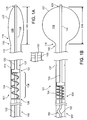
FIGS. 1A and 1B illustrate representative portions of anexample balloon catheter 101 having aspring member 104 that biases theballoon 107 in an extended state-for example, to facilitate deflation and withdrawal of theballoon 107 from a patient following a procedure. Biasing can include exerting a force that tends to cause theballoon 107 to be extended. That is, the bias force may be overcome by other forces (e.g., such as surface tension of the balloon when it is inflated), but absent other such forces, the bias force will tend to extend the balloon, preventing it from bunching up or otherwise having a larger diameter than its pre-inflation diameter. For purposes of example,FIG. 1A illustrates representative portions of thecatheter 101 when theballoon 107 is deflated, andFIG. 1B illustrates representative portions of thecatheter 101 when theballoon 107 is inflated. - The
spring member 104 described herein can be included in any kind of balloon catheter that may be employed to deliver therapy to treatment sites internal to a patient. For example, thespring member 104 can be included in a cryotherapy catheter for chilling or freezing tissue internal to a patient. As another example, thespring member 104 can be included in a radio-frequency (RF) balloon catheter, such as one that may be employed to deliver RF energy to a treatment site internal to a patient. As another example, thespring member 104 can be included in a balloon catheter configured to deliver a medical device, such as a stent, to a site internal to a patient. Other types of balloon catheters may similarly benefit from the inclusion of thespring member 104. - As shown in one example, the
balloon catheter 101 has acatheter shaft 110 and aninflatable balloon 107 disposed at adistal end 113 ofcatheter shaft 110. More specifically, aproximal end 116 of theinflatable balloon 107 is anchored to thedistal end 113 of thecatheter shaft 110. Aninterior chamber 119 can be defined by the walls or skin of theballoon 107. Although theballoon 107 is shown inFIGS. 1A and 1B as having a single wall, in some implementations, thecatheter 101 can employ two separate balloons-one of which may function as a safety balloon to protect a patient from agents inside a first balloon, in the event that the first balloon ruptures or otherwise fails inside the patient. Additional details of implementations involving a safety balloons are provided below. - An
elongate member 122 can be disposed inside theinflatable balloon 107. In some implementations, as depicted, theelongate member 122 is anchored to adistal end 125 of theinflatable balloon 107. In this example, theelongate member 122 is separate from and can translate within thecatheter shaft 110. Another portion of theelongate member 122 is coupled to thespring member 104. - One
end 128 of thespring member 104 can be anchored. In the example ofFIGS. 1A and 1B , thespring member 104 is anchored to thecatheter shaft 110. In other examples (e.g., those examples shown inFIGS. 3A or5 ), afirst end 128 of thespring member 104 can be anchored to another component of thecatheter 101. Asecond end 131 of thespring member 104 can be coupled to theelongate member 122 but can otherwise translate within achannel 134 that surrounds and is adjacent to thespring member 104. In some implementations, thechannel 134 is formed by thecatheter shaft 110 itself, and may be further bounded by a retainingmember 137, which may keep thespring member 104 compressed to some extent, even in its most extended state, as depicted inFIG. 1A . In other implementations, the retainingmember 137 does not normally contact the spring member 104 (e.g., absent a failure of the balloon 107). In some implementations, to help center thespring member 104 within thechannel 134, or to couple thespring member 104 to theelongate member 122, a disc 140 or other guide can be included. Such a disc 140 is described in more detail below. - With the
elongate member 122 coupled to thedistal end 125 of theballoon 107 and thesecond end 131 of thespring member 104, thespring member 104 can apply a distally-oriented longitudinal force to theballoon 107, through theelongate member 122. So that the majority of the compression force of thespring member 104 is applied to theballoon 107, any retaining member (e.g., the retaining member 137) can be positioned such that it does not normally contact the spring member. Moreover, theelongate member 122 can be made of a substantially non-compressible material (e.g., non-compressible, minimally compressible, or rigid, particularly in the longitudinal direction). That is, theelongate member 122 can be constructed such that translation of theelongate member 122 near thespring member 104 causes a corresponding translation of theelongate member 122 inside theballoon 107 of a substantially equivalent extent (e.g., within some relatively small margin, such as, for example, within 10%, 5%, 0.5%, etc.). Suitable substantially non-compressible materials can include, for example, braided materials (e.g., plastic tubes with embedded metal braiding) or hypotubes (e.g., steel hypotubes). - To further facilitate transfer of force from the
spring member 104 to theballoon 107 via theelongate member 122, thecatheter shaft 110 can include one or more retaining members, such as a retainingmember 143. In some implementations, the retainingmember 143 allows theelongate member 122 to translate relative to thecatheter shaft 110 while maintaining theelongate member 122 andcatheter shaft 110 in a substantially (e.g., within a relatively small margin, such as, 25%, 10%, 5%, 0.5%, etc.) co-axial relationship. - When viewed together,
FIGS. 1A and 1B illustrate the interplay between the state of the balloon 107 (e.g., whether theballoon 107 is inflated or deflated) and the state of the spring member 104 (e.g., whether and to what extent thespring member 104 is compressed). Specifically, with reference toFIG. 1B , inflation of theballoon 107 causes adistance 146 between thedistal region 125 andproximal region 116 of theballoon 107 to be approximately equal to the diameter of the balloon 107-assuming a balloon that inflates to a substantially spherical shape, as shown in one example inFIG. 1B . Thisdistance 146 is comparatively smaller than adistance 149 between thedistal region 125 andproximal region 116 of theballoon 107 when the balloon is not inflated, as shown inFIG. 1A . When theballoon 107 is not inflated, as depicted in one example inFIG. 1A , thespring member 104 is in its most extended state; when theballoon 107 is inflated, as depicted inFIG. 1B , thespring member 104 can be further compressed, beyond any state of initial compression. - To accommodate the translation of the
elongate member 122 on the proximal side of thespring member 104, some slack 152 can be provided in theelongate member 122. That is, for anelongate member 122 that is anchored to thecatheter shaft 110 at aproximal end 155 of thecatheter shaft 110, anextra length 152 of theelongate member 122 can be disposed between theproximal end 155 and thespring member 104, to accommodate for the difference between thedistance 146 and thedistance 149. - As will described in more detail below, the
elongate member 122 itself can serve different purposes - in addition to biasing theballoon 107. For example, in some implementations, theelongate member 122 is a guidewire lumen. In other implementations, theelongate member 122 is a supply lumen for providing a liquid or gas to theinterior chamber 119. In still other implementations, theelongate member 122 can be an exhaust lumen for extracting a liquid or gas from theinterior chamber 119. Additional details of theelongate member 122, and of thecatheter 101 in general, are now provided with reference toFIG. 2 . -
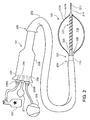
FIG. 2 illustrates additional details of theexample catheter 101 shown inFIGS. 1A and 1B . As shown in the example ofFIG. 2 , theballoon catheter 101 is disposed in adelivery sheath 202. In other implementations, thedelivery sheath 202 is not included. In some implementations that have a delivery sheath, thedelivery sheath 202 is a hollow tube that can be initially placed inside a patient and subsequently used as a conduit for other medical devices, such as theballoon catheter 101. For procedures in which several catheters may be employed (e.g., catheters of different sizes or characteristics, or catheters having different functions), thedelivery sheath 202 can protect the patient's internal body organs and body lumens through which the various medical devices are navigated. In addition, thedelivery sheath 202 can facilitate easier navigation of other medical devices, by a physician or other technician, to a treatment site. - The
delivery sheath 202 may be steerable, and it may have specific characteristics. For example, delivery sheaths may be available in varying diameters, such as 8.5 Fr (French), 10 Fr, 11 Fr, (2,8 mm, 3,3 mm, 3,7 mm) etc.; varying. lengths, such as 60 cm, 65 cm, 71 cm, 78 cm, 90 cm, etc.; and having distal ends that are biased in various shapes, such as, for example, in a 15° curve, a 55° curve, a short 120° curve, a long 120° curve, etc. Different delivery sheaths may be configured for different procedures. For example, a delivery sheath having one biased curvature may be particularly effective for guiding a cryo balloon to a patient's pulmonary veins to treat atrial fibrillation, while a delivery sheath having a different biased curvature may be particularly effective for guiding a stent-delivery balloon. - In some implementations, as depicted in
FIG. 2 , adistal tip 205 of thedelivery sheath 202 is slightly tapered to facilitate navigation of thetip 205 through a patient's vasculature, or to facilitate crossing of tissue membranes of the patient (e.g., the septal wall, during a procedure to treat atrial fibrillation). Theproximal end 208 may be tapered to more easily receive other medical devices, such as theballoon catheter 101 that is shown disposed in thedelivery sheath 202. - In the example of
FIG. 2 , theballoon catheter 101 is an over-the-wire cryotherapy balloon catheter, having aguidewire 211 disposed inside aguidewire lumen 214. The reader will appreciate that other types of balloon catheters can employ a spring member (not shown inFIG. 2 ) to apply a distally-oriented force to theballoon 107. For example, in other implementations, theballoon catheter 101 may not employ a guidewire 121. As another example, in other implementations, theballoon catheter 101 could be a radio frequency (RF) ablation catheter that remodels tissue with RF energy rather than by extracting heat using a cryogenic agent. - In the example
cryotherapy balloon catheter 101 shown inFIG. 2 , cryogenic fluid can be delivered from anexternal source 217 to theballoon 107 through asupply lumen 220, and released inside theinterior chamber 119, through a cooling device 223 (e.g., a coiled portion of thesupply lumen 220 having various orifices through which certain cryogenic agents can exit and undergo a liquid-to-gas phase change that cools theballoon 107 by the Joule-Thomson effect). Gas resulting from the cryogenic fluid being released and changing phase inside thechamber 119 can be exhausted through aseparate exhaust lumen 226. In particular, for example, in some implementations, gas is exhausted through anexhaust lumen 226 to anexternal vacuum pump 229. - To facilitate coupling the
catheter 101 to external equipment, such as thesource 217 of a cryogenic agent or thevacuum pump 229, thecatheter 101 can include aport component 232 having a number ofcoupling members coupling members supply lumen 220 and an exhaust lumen 226) with connectors (e.g., industry-standard medical connectors, proprietary medical connectors, other connectors, etc.) that facilitate connection of thelumens port component 232 can also provide access to theguidewire lumen 214 andcorresponding guidewire 211. As shown inFIG. 2 , theport component 232 is merely exemplary. Other connections and configurations are possible and contemplated (e.g., connections for pressure sensor(s), electrical sensor(s), multiple vacuum ports, etc.). - As mentioned above and shown in
FIG. 2 , twoseparate balloons catheter shaft 110. Theballoons second balloon 107B functions as asafety balloon 107B. That is, in the event that theballoon 107A ruptures or otherwise fails, thesafety balloon 107B can prevent agents inside the interior chamber 119 (e.g., cryogenic agents) from directly contacting body tissue internal to the patient and can similarly prevent body tissue and body fluids from reaching theinterior chamber 119. In some implementations, a separate vacuum lumen (not shown) is provided between theballoons balloons inner balloon 107A ruptures, the constant vacuum force can continue to evacuate any liquid and/or gas inside theinterior chamber 119 and prevent the same from coming into direct contact with tissue internal to the patient. If eitherinner balloon 107A orouter balloon 107B ruptures, a sensor that monitors the vacuum force between theballoons - As mentioned above, the spring member 104 (not shown in
FIG. 2 ) can be disposed in various positions within thecatheter 101. For example, in some implementations, as described with reference toFIGS. 3A-3D , aspring member 104A is disposed in theport component 232. In other implementations, as described with reference toFIG. 4 , aspring member 104B is disposed in thecatheter shaft 110, in close proximity to the distal end 113 (seeFIG. 1A ) to which theproximal end 116 of theballoon 107 is anchored (e.g., within a short distance, such as within 10 cm, 5 cm, 1 cm, etc., or within a small percentage of the overall length of the catheter shaft, such as within 20%, 10%, 2%, etc., of the overall length). Thespring member 104 can also be employed to provide distally-oriented longitudinal force to various lumens, such as, for example, a supply lumen (e.g., as described with reference toFIGS. 3A-3D and4A-B ), exhaust lumen, guidewire lumen (e.g., as described with reference toFIG. 5 ), or other catheter structure (e.g., another lumen, or a standalone structure). -
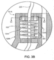
FIG. 3A is a cutaway illustration of one example implementation in which aspring member 104A is provided in theport component 232. Specifically, as depicted in this example, thespring member 104A is coupled to thesupply lumen 220 of theexample cryotherapy catheter 101. More specifically, afirst end 128A of thespring member 104A is anchored to theport component 232, and asecond end 131 A of thespring member 104A is coupled to thesupply lumen 220, in order to exert a distally-oriented longitudinal force on thesupply lumen 220. In this example, although theballoon 107 is not shown inFIG. 3A , thesupply lumen 220 can be anchored to thedistal end 125 of theballoon 107 and can otherwise translate within thecatheter shaft 110. - As depicted in this example, an exhaust space 303 couples to an
exhaust lumen 226 in thecatheter shaft 110, and within theport component 232, the exhaust space 303 is approximately coaxial with the supply lumen 220 (e.g., within some amount of deviation caused byslack 306 in the supply lumen 220). For context, aguidewire lumen 214 is shown in theport component 232, along with asecondary exhaust path 309. In some implementations, thesecondary exhaust path 309 is coupled to a lumen (not shown) that evacuates the above-described space between theballoons FIG. 2 . As shown inFIG. 3A , afilter 307 can be included in a coupling member for coupling the exhaust space 303 and/or thesupply lumen 220 to the external equipment. Additional details of thespring member 104A in this implementation are now provided with reference toFIGS. 3B-3D . -
FIG. 3B illustrates additional details of thespring member 104A that is shown inFIG. 3A . As depicted, thespring member 104A is anchored to theport component 232 at afirst end 128A. Asecond end 131A is anchored to adisc 312, which can translate within achannel 134A formed in theport component 232. Thedisc 312 is attached to thesupply lumen 220, such that as thedisc 312 translates within thechannel 134A (e.g., in response to the force exerted by thespring member 104A, or a force transmitted from theballoon 107 via the supply lumen 220 (e.g., when theballoon 107 is inflated)). As will be described with reference toFIG. 3C , a space within thespring member 104A and around thesupply lumen 220 can serve as aconduit 305 for exhaust. -
FIG. 3C illustrates additional example details of thedisc 312. In the example depicted, thedisc 312 is circular in shape, such that it can translate within acylindrical channel 134A formed in theport component 232. Anopening 315 is provided to receive and retain thesupply lumen 220, andadditional openings 318 are provided to allow exhaust to pass through thespring member 104A.FIG. 3D is a perspective view further illustrating thespring member 104A,disc 312,supply lumen 220 andexhaust conduit 305. -
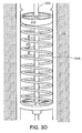
FIGS. 4A and 4B illustrate another implementation in which aspring member 104B is disposed within thecatheter shaft 110, in close proximity to thedistal end 113 to which theproximal end 116 of theballoon 107 is anchored (e.g., within a short distance, such as within 10 cm, 5 cm, 1cm, etc., or within a small percentage of the overall length of the catheter shaft, such as within 20%, 10%, 2%, etc., of the overall length). -
FIG. 4A illustrates the balloon 107 (or more precisely, theballoons force 403 provided by thespring member 104B biases theballoon 107 in a extended state. In particular, biasing theballoon 107 distally causes aninward force 406 to be applied to the walls of the balloon. More precisely, the force on theelongate member 122 is transferred to the walls of theballoon 107, as atangential force 409. To the extent that the walls of the balloon are not parallel to the longitudinal force (e.g., the walls of the balloon are shown slightly bowed inFIG. 4A ), thetangential force 409 has aradial component 410 that pulls the balloon walls inward. -
FIG. 4B illustrates theballoon 107 in an inflated state, with thespring member 104B compressed to a greater extent than its state inFIG. 4A . In particular, pressure in theinterior chamber 119, which inflates theballoon 107, applies anoutward force 415 to the walls of the balloon. Thisoutward force 415 is transferred to the walls of theballoon 107 as atangential force 421, and as depicted, thetangential force 421 force has a longitudinal, oraxial component 424, which opposes the bias force provided by thespring member 104B, causing thespring member 104B to be compressed as shown. - The
spring member 104B in the example ofFIGS. 4A and 4B can be coupled, for example, to a guidewire lumen (if present) or to a supply lumen. Alternatively, thespring member 104B could be coupled to a standalone balloon structure, such as a rod or other structural element specifically configured to bias thedistal end 125 of the balloon in an extended state. - The
spring member 104B can have a similar construction as is depicted inFIGS. 3B-3D , with appropriate modification to accommodate necessary lumens and other catheter structures that pass through or adjacent to the spring member. In particular, for example, additional openings can be disposed in adisc 412 associated with aspring member 104B, such that other lumens that are not coupled to thedisc 412 can pass through thespring member 104B. Alternatively, thespring member 104B, and channel that thespring member 104B occupies, can have a smaller diameter than thecatheter shaft 110 at that point, such that other lumens can pass through thecatheter shaft 110 adjacent to thespring member 104B. In particular, for example, in implementations in which thespring member 104B couples to a guidewire lumen, a supply lumen can be routed adjacent to thespring member 104B, and an exhaust channel can flow through thespring member 104B as described above. - In some implementations, the
spring member 104B is advantageously disposed near thedistal end 113 of thecatheter shaft 110. In such implementations, thespring member 104B may require less compression force to bias theballoon 107, since the compression force may not have to overcome as much resistance to the distally-oriented longitudinal force presented by the length of theelongate member 122 between theballoon 107 and thespring member 104B. In particular, a distally disposedspring member 104 may not have to overcome as much resistance presented by curves or bends in theelongate member 122 that may be present when thecatheter 101 is employed to provide treatment inside a patient-particularly when thecatheter 101 is routed through a tortuous vascular pathway (e.g., to reach a patient's left atrium, from the patient's right femoral artery). - Regardless of where the
spring member 104 is disposed (e.g., in thedistal end 113 of thecatheter shaft 110, as shown inFIGS. 4A and 4B , or in theport component 232, as shown inFIG. 3A ), forces and tensions of various components can be properly configured to enable the states depicted inFIGS. 4A and 4B . That is, the distally-oriented force provided by thespring member 104B should be sufficient to bias theballoon 107 in an extended state when theballoon 107 is not inflated, as shown inFIG. 4A . On the other hand, thespring member 104B should not be so stiff that it is not able to be compressed when theballoon 107 is inflated (as inFIG. 4B ). Thus, for aballoon 107 whose material is very elastic, thespring member 104 may be less stiff than aspring member 104 employed with a balloon whose material is less elastic. Other forces should be considered. For example, as mentioned above, implementations in which thespring member 104A is disposed in the port component 232 (or at other, more proximal locations within the catheter shaft), thespring member 104A may need to be stiffer in order to overcome resistance to translation of theelongate member 122 that may be presented by bends or twists in thecatheter shaft 110. -
FIG. 5 illustrates another example implementation in which aspring member 104C can be disposed in theport component 232 and coupled to a central guidewire lumen. As depicted inFIG. 5 , theguidewire lumen 214 can be constructed of a substantially non-compressible material, such that the majority of the distally-oriented force provided by the spring member is communicated to thedistal end 125 of theballoon 107. Other lumens and structures of thecatheter 101 can be disposed in any appropriate manner. As shown in one example inFIG. 5 , asupply lumen 220, anexhaust lumen 226, anauxiliary exhaust lumen 501, a pressure lumen 504 (e.g., for coupling to a pressure sensor external to thecatheter 101, such that pressure inside the balloon can be measured), and other lumens and structures can be routed within thecatheter shaft 110 and adjacent to theguidewire lumen 214. For purposes of illustration, a proximal end 507 of theguidewire 211 itself is shown extending from theproximal end 510 of theguidewire lumen 214. - A number of implementations have been described. Nevertheless, it will be understood that various modifications may be made without departing from the scope of this document. In particular, the above description refers to a cryotherapy balloon catheter for purpose of example, but a spring member as described herein can be included in other types of balloon catheters. Cryotherapy balloon catheters are described as employing the Joule-Thomson effect to cool using a liquid-to-gas phase change, but liquid-based cryocatheters can also include spring members. The spring member can be disposed at various points within a catheter, and the specific points described herein are merely exemplary. In some implementations, the spring member can be external to the catheter; for example, the spring member could be included in a connector that couples external equipment to the catheter and could impinge on a lumen or other internal structure of the catheter to provide the distally-oriented force. Other types of port components can be employed. Multiple spring members can be employed in multiple locations. Spring members, lumens and other catheter structures can have any suitable construction, and can be made from any suitable material. In particular, for example, coiled springs are depicted by way of example, but the reader will appreciate that other devices that exert a spring force when compressed can be employed as spring members. Accordingly, other implementations are within the scope of the following claims.
Claims (13)
- A balloon catheter (101) comprising:a catheter shaft (110) having a proximal end (155) and a distal end (113);an inflatable balloon (107) having a proximal end (116) that is anchored to the distal end (113) of the catheter shaft;an elongate member (122) that is separate from and disposed inside the catheter shaft (110), extends into an interior chamber (119) of the inflatable balloon (107), and is anchored to a distal end (125) of the inflatable balloon; anda spring member (104) that exerts a distally-oriented longitudinal force on the elongate member (122), relative to the catheter shaft, wherein the distally-oriented longitudinal force causes the inflatable balloon (107) to be biased in an extended position, away from the distal end (113) of the catheter shaft (110); characterised wherein some slack in the form of an extra length of the elongate member (122) is disposed proximally of the spring member (104).
- The balloon catheter of claim 1, further comprising a port component (232) at the proximal end (155) of the catheter shaft (110), the port component having a coupling member (235A, 235B) for fluidly coupling a lumen disposed inside the catheter shaft (110) to a device that is external to the balloon catheter (101).
- The balloon catheter of claim 2, wherein the spring member is disposed in the port component.
- The balloon catheter of claim 2 or 3, wherein a first end (128A) of the spring member (104A) is mounted to the port component (232), and a second end (131A) of the spring member (104) is mounted to the elongate member (122); wherein the second end is configured to slideably translate within a channel (134A) that is in the port component (232) and adjacent to the spring member (104A).
- The balloon catheter of claim 4, wherein the spring member (104A) is configured such that the second end (131A) translates away from the inflatable balloon (107) when the inflatable balloon is inflated, thereby compressing the spring member (104A) beyond an initial compressed state, and translates toward the inflatable balloon (107) to exert the distally-oriented longitudinal force when the inflatable balloon (107) is not inflated.
- The balloon catheter of claim 5, wherein the elongate member (122) is a supply lumen (220).
- The balloon catheter of claim 5, wherein the elongate member (122) is constructed from a material that is substantially non-compressible longitudinally, such that translation of the elongate member at the port component (232) causes a corresponding translation of the elongate member in the interior chamber (119) of a substantially equivalent extent.
- The balloon catheter of claim 7, wherein the elongate member (122) comprises at least one of a braided material or a hypotube.
- The balloon catheter of any of the preceding claims, further comprising a sheath (202) configured to receive the catheter shaft (110) and the inflatable balloon (107); wherein the inflatable balloon (107) is configured to be advanced to through the sheath (202) to a treatment site outside the sheath and inflated for the treatment procedure, and deflated and withdrawn back into the sheath following the treatment procedure.
- The balloon catheter of claim 9, wherein the spring member (104; 104A) is configured to exert the distally-oriented longitudinal force in a manner that facilitates deflation and withdrawal of the inflatable balloon (107) into the sheath.
- The balloon catheter of claim 2, wherein the elongate member (122) comprises at least one of a guidewire lumen (214), a supply lumen (220) for supplying a liquid or gas from an external source to the interior chamber (119), or an exhaust lumen (226) for exhausting a liquid or gas from the interior chamber (119) to a region exterior to the balloon catheter.
- The balloon catheter of claim 1, wherein the spring member is disposed inside the catheter shaft (110) and in close proximity to the distal end of the catheter shaft and a first end (128) of the spring member is anchored at the catheter shaft and a second end (131) of the spring member is coupled to the elongate member (122).
- The balloon catheter of any of the preceding claims, wherein the inflatable balloon (107) is configured to deliver cryotherapy to a treatment site.
Applications Claiming Priority (2)
| Application Number | Priority Date | Filing Date | Title |
|---|---|---|---|
| US9902108P | 2008-09-22 | 2008-09-22 | |
| PCT/US2009/057452 WO2010033785A1 (en) | 2008-09-22 | 2009-09-18 | Biasing a catheter balloon |
Publications (2)
| Publication Number | Publication Date |
|---|---|
| EP2334365A1 EP2334365A1 (en) | 2011-06-22 |
| EP2334365B1 true EP2334365B1 (en) | 2016-10-26 |
Family
ID=41259982
Family Applications (1)
| Application Number | Title | Priority Date | Filing Date |
|---|---|---|---|
| EP09792702.4A Active EP2334365B1 (en) | 2008-09-22 | 2009-09-18 | Biasing a catheter balloon |
Country Status (6)
| Country | Link |
|---|---|
| US (1) | US8333757B2 (en) |
| EP (1) | EP2334365B1 (en) |
| JP (1) | JP5577343B2 (en) |
| KR (1) | KR20110063551A (en) |
| CA (1) | CA2737272A1 (en) |
| WO (1) | WO2010033785A1 (en) |
Cited By (1)
| Publication number | Priority date | Publication date | Assignee | Title |
|---|---|---|---|---|
| US20210016067A1 (en) | 2018-01-12 | 2021-01-21 | Biosense Webster (Israel) Ltd | Balloon Catheter Assisted by Pulling a Puller-Wire |
Families Citing this family (67)
| Publication number | Priority date | Publication date | Assignee | Title |
|---|---|---|---|---|
| US7780723B2 (en) | 2005-06-13 | 2010-08-24 | Edwards Lifesciences Corporation | Heart valve delivery system |
| US9061119B2 (en) | 2008-05-09 | 2015-06-23 | Edwards Lifesciences Corporation | Low profile delivery system for transcatheter heart valve |
| US8652202B2 (en) | 2008-08-22 | 2014-02-18 | Edwards Lifesciences Corporation | Prosthetic heart valve and delivery apparatus |
| US10695126B2 (en) | 2008-10-06 | 2020-06-30 | Santa Anna Tech Llc | Catheter with a double balloon structure to generate and apply a heated ablative zone to tissue |
| US8465481B2 (en) * | 2008-10-20 | 2013-06-18 | Boston Scientific Scimed, Inc. | Providing cryotherapy with a balloon catheter having a non-uniform thermal profile |
| WO2010093603A1 (en) | 2009-02-11 | 2010-08-19 | Boston Scientific Scimed, Inc. | Insulated ablation catheter devices and methods of use |
| US20100274189A1 (en) * | 2009-04-22 | 2010-10-28 | Pressure Products Medical Supplies Inc. | Balloon catheter and method of manufacture of the same |
| US8827952B2 (en) * | 2010-12-06 | 2014-09-09 | Boston Scientific Scimed, Inc. | Biasing mechanism for a balloon catheter |
| US8790300B2 (en) | 2010-12-06 | 2014-07-29 | Boston Scientific Scimed, Inc. | Dual balloon catheter |
| US9155619B2 (en) | 2011-02-25 | 2015-10-13 | Edwards Lifesciences Corporation | Prosthetic heart valve delivery apparatus |
| US9119716B2 (en) | 2011-07-27 | 2015-09-01 | Edwards Lifesciences Corporation | Delivery systems for prosthetic heart valve |
| US9364637B2 (en) * | 2011-09-06 | 2016-06-14 | Medtronic, Inc. | Transcatheter balloon-assisted mitral valve navigation device and method |
| JP6072804B2 (en) * | 2011-09-14 | 2017-02-01 | ボストン サイエンティフィック サイムド,インコーポレイテッドBoston Scientific Scimed,Inc. | Ablation device with ion conductive balloon |
| WO2013040201A2 (en) | 2011-09-14 | 2013-03-21 | Boston Scientific Scimed, Inc. | Ablation device with multiple ablation modes |
| DE102011085616A1 (en) * | 2011-11-02 | 2013-05-02 | Celon Ag Medical Instruments | Electrosurgical probe and electrosurgery device |
| JP2015506234A (en) | 2012-01-10 | 2015-03-02 | ボストン サイエンティフィック サイムド,インコーポレイテッドBoston Scientific Scimed,Inc. | Electrophysiology system |
| EP2617456A1 (en) * | 2012-01-19 | 2013-07-24 | VascoMed GmbH | Catheter and catheter system |
| US9168080B2 (en) | 2012-01-27 | 2015-10-27 | Medtronic Cryocath Lp | Balloon catheter |
| WO2013115941A1 (en) | 2012-01-31 | 2013-08-08 | Boston Scientific Scimed, Inc. | Ablation probe with fluid-based acoustic coupling for ultrasonic tissue imaging |
| US10610294B2 (en) | 2012-04-22 | 2020-04-07 | Newuro, B.V. | Devices and methods for transurethral bladder partitioning |
| US9883906B2 (en) | 2012-04-22 | 2018-02-06 | Newuro, B.V. | Bladder tissue modification for overactive bladder disorders |
| WO2013160772A2 (en) | 2012-04-22 | 2013-10-31 | Omry Ben-Ezra | Bladder tissue modification for overactive bladder disorders |
| WO2014043687A2 (en) * | 2012-09-17 | 2014-03-20 | Boston Scientific Scimed, Inc. | Self-positioning electrode system and method for renal nerve modulation |
| US11938287B2 (en) | 2012-10-26 | 2024-03-26 | Urotronic, Inc. | Drug-coated balloon catheters for body lumens |
| US10881839B2 (en) | 2012-10-26 | 2021-01-05 | Urotronic, Inc. | Drug-coated balloon catheters for body lumens |
| US10850076B2 (en) | 2012-10-26 | 2020-12-01 | Urotronic, Inc. | Balloon catheters for body lumens |
| US10806830B2 (en) | 2012-10-26 | 2020-10-20 | Urotronic, Inc. | Drug-coated balloon catheters for body lumens |
| US11504450B2 (en) | 2012-10-26 | 2022-11-22 | Urotronic, Inc. | Drug-coated balloon catheters for body lumens |
| US10898700B2 (en) | 2012-10-26 | 2021-01-26 | Urotronic, Inc. | Balloon catheters for body lumens |
| CZ306454B6 (en) * | 2013-03-28 | 2017-02-01 | Ella-Cs, S.R.O. | A catheter for inserting plastic stents |
| JP6742295B2 (en) | 2014-07-28 | 2020-08-19 | スマート・メディカル・システムズ・リミテッド | User Operatable Controlled Wrap Balloon Assembly And Method For Controlled Wrap Of Balloons |
| US10524684B2 (en) | 2014-10-13 | 2020-01-07 | Boston Scientific Scimed Inc | Tissue diagnosis and treatment using mini-electrodes |
| US10603105B2 (en) | 2014-10-24 | 2020-03-31 | Boston Scientific Scimed Inc | Medical devices with a flexible electrode assembly coupled to an ablation tip |
| US9743854B2 (en) | 2014-12-18 | 2017-08-29 | Boston Scientific Scimed, Inc. | Real-time morphology analysis for lesion assessment |
| CN118320191A (en) | 2015-04-24 | 2024-07-12 | 优敦力公司 | Drug coated balloon catheter for non-vascular stenosis |
| US11904072B2 (en) | 2015-04-24 | 2024-02-20 | Urotronic, Inc. | Drug coated balloon catheters for nonvascular strictures |
| US9907610B2 (en) * | 2015-05-07 | 2018-03-06 | Biosense Webster (Israel) Ltd. | Spring-loaded balloon |
| US10179046B2 (en) | 2015-08-14 | 2019-01-15 | Edwards Lifesciences Corporation | Gripping and pushing device for medical instrument |
| US11259920B2 (en) | 2015-11-03 | 2022-03-01 | Edwards Lifesciences Corporation | Adapter for prosthesis delivery device and methods of use |
| US10321996B2 (en) | 2015-11-11 | 2019-06-18 | Edwards Lifesciences Corporation | Prosthetic valve delivery apparatus having clutch mechanism |
| US11219746B2 (en) | 2016-03-21 | 2022-01-11 | Edwards Lifesciences Corporation | Multi-direction steerable handles for steering catheters |
| US10799676B2 (en) | 2016-03-21 | 2020-10-13 | Edwards Lifesciences Corporation | Multi-direction steerable handles for steering catheters |
| US10799677B2 (en) | 2016-03-21 | 2020-10-13 | Edwards Lifesciences Corporation | Multi-direction steerable handles for steering catheters |
| US11331140B2 (en) | 2016-05-19 | 2022-05-17 | Aqua Heart, Inc. | Heated vapor ablation systems and methods for treating cardiac conditions |
| US10821272B2 (en) * | 2016-11-23 | 2020-11-03 | Biosense Webster (Israel) Ltd. | Double balloon catheter having a lobed inner balloon |
| US11400205B2 (en) | 2016-11-23 | 2022-08-02 | Biosense Webster (Israel) Ltd. | Balloon-in-balloon irrigation balloon catheter |
| CN106823111A (en) * | 2016-12-13 | 2017-06-13 | 庞继恩 | A kind of heart intervention treating expansion foley's tube |
| CN110719796B (en) | 2017-04-10 | 2022-05-24 | 医盟科技股份有限公司 | Catheter for draining body fluids |
| US11224511B2 (en) | 2017-04-18 | 2022-01-18 | Edwards Lifesciences Corporation | Heart valve sealing devices and delivery devices therefor |
| JP7204665B2 (en) | 2017-04-18 | 2023-01-16 | エドワーズ ライフサイエンシーズ コーポレイション | Heart valve sealing device and its delivery device |
| US10973634B2 (en) | 2017-04-26 | 2021-04-13 | Edwards Lifesciences Corporation | Delivery apparatus for a prosthetic heart valve |
| US10959846B2 (en) | 2017-05-10 | 2021-03-30 | Edwards Lifesciences Corporation | Mitral valve spacer device |
| KR20200020862A (en) * | 2017-06-23 | 2020-02-26 | 가부시키가이샤 굿맨 | Balloon Catheter |
| US10350395B2 (en) | 2017-06-23 | 2019-07-16 | Cook Medical Technologies Llc | Introducer for lumen support or dilation |
| EP3644903B1 (en) | 2017-06-30 | 2023-07-19 | Edwards Lifesciences Corporation | Docking stations for transcatheter valves |
| JP2020526274A (en) | 2017-06-30 | 2020-08-31 | エドワーズ ライフサイエンシーズ コーポレイションEdwards Lifesciences Corporation | Locking and releasing mechanism for transcatheter implantable devices |
| US10857334B2 (en) | 2017-07-12 | 2020-12-08 | Edwards Lifesciences Corporation | Reduced operation force inflator |
| US10806573B2 (en) | 2017-08-22 | 2020-10-20 | Edwards Lifesciences Corporation | Gear drive mechanism for heart valve delivery apparatus |
| US11051939B2 (en) | 2017-08-31 | 2021-07-06 | Edwards Lifesciences Corporation | Active introducer sheath system |
| SG11202002918YA (en) | 2017-10-18 | 2020-05-28 | Edwards Lifesciences Corp | Catheter assembly |
| US11207499B2 (en) | 2017-10-20 | 2021-12-28 | Edwards Lifesciences Corporation | Steerable catheter |
| US11844914B2 (en) | 2018-06-05 | 2023-12-19 | Edwards Lifesciences Corporation | Removable volume indicator for syringe |
| US11779728B2 (en) | 2018-11-01 | 2023-10-10 | Edwards Lifesciences Corporation | Introducer sheath with expandable introducer |
| JP2022521000A (en) | 2019-02-22 | 2022-04-04 | ウロトロニック・インコーポレイテッド | Drug-coated balloon catheter for body cavity |
| JP2020171601A (en) * | 2019-04-12 | 2020-10-22 | 株式会社東海メディカルプロダクツ | Balloon catheter |
| WO2022046591A1 (en) | 2020-08-24 | 2022-03-03 | Edwards Lifesciences Corporation | Balloon cover for a delivery apparatus for an expandable prosthetic heart valve |
| CN216455494U (en) | 2020-08-31 | 2022-05-10 | 爱德华兹生命科学公司 | System for crimping a prosthetic implant to a delivery device and crimping system |
Family Cites Families (19)
| Publication number | Priority date | Publication date | Assignee | Title |
|---|---|---|---|---|
| GB1288033A (en) * | 1968-10-31 | 1972-09-06 | ||
| US4276874A (en) * | 1978-11-15 | 1981-07-07 | Datascope Corp. | Elongatable balloon catheter |
| US4315512A (en) * | 1980-01-24 | 1982-02-16 | Fogarty Thomas J | Piston extension balloon dilatation catheter apparatus and method |
| US5209727A (en) * | 1992-01-29 | 1993-05-11 | Interventional Technologies, Inc. | Guide wire with integral angioplasty balloon |
| US5423755A (en) * | 1992-08-26 | 1995-06-13 | Advanced Cardiovascular Systems, Inc. | Catheter for prostatic urethral dilatation |
| NL9500173A (en) * | 1995-01-31 | 1996-09-02 | Cordis Europ | Balloon catheter with rigid, elastically deformable base body. |
| US7220257B1 (en) * | 2000-07-25 | 2007-05-22 | Scimed Life Systems, Inc. | Cryotreatment device and method |
| US7425212B1 (en) * | 1998-06-10 | 2008-09-16 | Asthmatx, Inc. | Devices for modification of airways by transfer of energy |
| CA2346460C (en) | 1998-10-05 | 2007-07-24 | Kaneka Corporation | Balloon catheter and method for manufacturing same |
| US6575933B1 (en) * | 1998-11-30 | 2003-06-10 | Cryocath Technologies Inc. | Mechanical support for an expandable membrane |
| JP2001238953A (en) * | 2000-02-29 | 2001-09-04 | Nippon Zeon Co Ltd | Balloon catheter |
| US7497844B2 (en) * | 2000-03-31 | 2009-03-03 | Medtronic, Inc. | System and method for positioning implantable medical devices within coronary veins |
| AU7347101A (en) * | 2000-07-13 | 2002-01-30 | Transurgical Inc | Thermal treatment methods and apparatus with focused energy application |
| US6733439B2 (en) * | 2001-03-12 | 2004-05-11 | Apti Inc. | Centering mechanism for probe |
| US6929639B2 (en) * | 2002-08-30 | 2005-08-16 | Scimed Life Systems, Inc. | Cryo ablation coil |
| US6964661B2 (en) * | 2003-04-02 | 2005-11-15 | Boston Scientific Scimed, Inc. | Endovenous ablation mechanism with feedback control |
| WO2005063137A2 (en) * | 2003-12-22 | 2005-07-14 | Ams Research Corporation | Cryosurgical devices for endometrial ablation |
| US9039712B2 (en) | 2006-06-28 | 2015-05-26 | Medtronic Cryocath Lp | Shape modification system for a cooling chamber of a medical device |
| EP2173427B1 (en) * | 2007-07-09 | 2011-11-30 | Cook Medical Technologies LLC | Balloon folding control mechanism |
-
2009
- 2009-09-18 EP EP09792702.4A patent/EP2334365B1/en active Active
- 2009-09-18 JP JP2011527988A patent/JP5577343B2/en active Active
- 2009-09-18 CA CA2737272A patent/CA2737272A1/en not_active Abandoned
- 2009-09-18 KR KR1020117008994A patent/KR20110063551A/en not_active Application Discontinuation
- 2009-09-18 WO PCT/US2009/057452 patent/WO2010033785A1/en active Application Filing
- 2009-09-18 US US12/562,386 patent/US8333757B2/en active Active
Cited By (2)
| Publication number | Priority date | Publication date | Assignee | Title |
|---|---|---|---|---|
| US20210016067A1 (en) | 2018-01-12 | 2021-01-21 | Biosense Webster (Israel) Ltd | Balloon Catheter Assisted by Pulling a Puller-Wire |
| US11826529B2 (en) | 2018-01-12 | 2023-11-28 | Biosense Webster (Israel) Ltd. | Balloon catheter assisted by pulling a puller-wire |
Also Published As
| Publication number | Publication date |
|---|---|
| JP5577343B2 (en) | 2014-08-20 |
| US20100076402A1 (en) | 2010-03-25 |
| KR20110063551A (en) | 2011-06-10 |
| CA2737272A1 (en) | 2010-03-25 |
| EP2334365A1 (en) | 2011-06-22 |
| US8333757B2 (en) | 2012-12-18 |
| JP2012502759A (en) | 2012-02-02 |
| WO2010033785A1 (en) | 2010-03-25 |
Similar Documents
| Publication | Publication Date | Title |
|---|---|---|
| EP2334365B1 (en) | Biasing a catheter balloon | |
| US8827952B2 (en) | Biasing mechanism for a balloon catheter | |
| US11819452B2 (en) | Balloon catheter | |
| US7785289B2 (en) | Catheter with flexible, non-kinking elongate member | |
| US8790300B2 (en) | Dual balloon catheter | |
| US9757137B2 (en) | Apparatus and methods for treating obstructions within body lumens | |
| US9888953B2 (en) | Nested balloon cryotherapy | |
| EP2037994B1 (en) | Shape modification system for a cooling chamber of a medical device | |
| EP2387964B1 (en) | Wide area ablation of myocardial tissue | |
| US8821485B2 (en) | Employing a secondary sheath with an ablation catheter | |
| US20130110106A1 (en) | Expandable structure for off-wall ablation electrode | |
| EP3065657A1 (en) | Catheter for plaque stablisation | |
| WO2013110158A1 (en) | Balloon catheter | |
| JP2009537211A (en) | Balloon catheter | |
| US20190307499A1 (en) | Ablation device having a sheath with a dilatable member for fixation and/or support of an ablation applicator, and method of operating an ablation device | |
| US20230363811A1 (en) | Gallbladder cryoablation device and method |
Legal Events
| Date | Code | Title | Description |
|---|---|---|---|
| PUAI | Public reference made under article 153(3) epc to a published international application that has entered the european phase |
Free format text: ORIGINAL CODE: 0009012 |
|
| 17P | Request for examination filed |
Effective date: 20110406 |
|
| AK | Designated contracting states |
Kind code of ref document: A1 Designated state(s): AT BE BG CH CY CZ DE DK EE ES FI FR GB GR HR HU IE IS IT LI LT LU LV MC MK MT NL NO PL PT RO SE SI SK SM TR |
|
| AX | Request for extension of the european patent |
Extension state: AL BA RS |
|
| DAX | Request for extension of the european patent (deleted) | ||
| 17Q | First examination report despatched |
Effective date: 20120427 |
|
| RIC1 | Information provided on ipc code assigned before grant |
Ipc: A61M 25/06 20060101ALI20160111BHEP Ipc: A61M 25/10 20060101AFI20160111BHEP Ipc: A61M 25/00 20060101ALI20160111BHEP |
|
| GRAP | Despatch of communication of intention to grant a patent |
Free format text: ORIGINAL CODE: EPIDOSNIGR1 |
|
| INTG | Intention to grant announced |
Effective date: 20160225 |
|
| GRAS | Grant fee paid |
Free format text: ORIGINAL CODE: EPIDOSNIGR3 |
|
| GRAA | (expected) grant |
Free format text: ORIGINAL CODE: 0009210 |
|
| AK | Designated contracting states |
Kind code of ref document: B1 Designated state(s): AT BE BG CH CY CZ DE DK EE ES FI FR GB GR HR HU IE IS IT LI LT LU LV MC MK MT NL NO PL PT RO SE SI SK SM TR |
|
| REG | Reference to a national code |
Ref country code: GB Ref legal event code: FG4D |
|
| REG | Reference to a national code |
Ref country code: CH Ref legal event code: EP |
|
| REG | Reference to a national code |
Ref country code: AT Ref legal event code: REF Ref document number: 839583 Country of ref document: AT Kind code of ref document: T Effective date: 20161115 |
|
| REG | Reference to a national code |
Ref country code: IE Ref legal event code: FG4D |
|
| REG | Reference to a national code |
Ref country code: DE Ref legal event code: R096 Ref document number: 602009041987 Country of ref document: DE |
|
| REG | Reference to a national code |
Ref country code: LT Ref legal event code: MG4D |
|
| PG25 | Lapsed in a contracting state [announced via postgrant information from national office to epo] |
Ref country code: LV Free format text: LAPSE BECAUSE OF FAILURE TO SUBMIT A TRANSLATION OF THE DESCRIPTION OR TO PAY THE FEE WITHIN THE PRESCRIBED TIME-LIMIT Effective date: 20161026 |
|
| REG | Reference to a national code |
Ref country code: NL Ref legal event code: MP Effective date: 20161026 |
|
| REG | Reference to a national code |
Ref country code: AT Ref legal event code: MK05 Ref document number: 839583 Country of ref document: AT Kind code of ref document: T Effective date: 20161026 |
|
| PG25 | Lapsed in a contracting state [announced via postgrant information from national office to epo] |
Ref country code: GR Free format text: LAPSE BECAUSE OF FAILURE TO SUBMIT A TRANSLATION OF THE DESCRIPTION OR TO PAY THE FEE WITHIN THE PRESCRIBED TIME-LIMIT Effective date: 20170127 Ref country code: NO Free format text: LAPSE BECAUSE OF FAILURE TO SUBMIT A TRANSLATION OF THE DESCRIPTION OR TO PAY THE FEE WITHIN THE PRESCRIBED TIME-LIMIT Effective date: 20170126 Ref country code: LT Free format text: LAPSE BECAUSE OF FAILURE TO SUBMIT A TRANSLATION OF THE DESCRIPTION OR TO PAY THE FEE WITHIN THE PRESCRIBED TIME-LIMIT Effective date: 20161026 Ref country code: SE Free format text: LAPSE BECAUSE OF FAILURE TO SUBMIT A TRANSLATION OF THE DESCRIPTION OR TO PAY THE FEE WITHIN THE PRESCRIBED TIME-LIMIT Effective date: 20161026 |
|
| PG25 | Lapsed in a contracting state [announced via postgrant information from national office to epo] |
Ref country code: ES Free format text: LAPSE BECAUSE OF FAILURE TO SUBMIT A TRANSLATION OF THE DESCRIPTION OR TO PAY THE FEE WITHIN THE PRESCRIBED TIME-LIMIT Effective date: 20161026 Ref country code: HR Free format text: LAPSE BECAUSE OF FAILURE TO SUBMIT A TRANSLATION OF THE DESCRIPTION OR TO PAY THE FEE WITHIN THE PRESCRIBED TIME-LIMIT Effective date: 20161026 Ref country code: PT Free format text: LAPSE BECAUSE OF FAILURE TO SUBMIT A TRANSLATION OF THE DESCRIPTION OR TO PAY THE FEE WITHIN THE PRESCRIBED TIME-LIMIT Effective date: 20170227 Ref country code: BE Free format text: LAPSE BECAUSE OF FAILURE TO SUBMIT A TRANSLATION OF THE DESCRIPTION OR TO PAY THE FEE WITHIN THE PRESCRIBED TIME-LIMIT Effective date: 20161026 Ref country code: PL Free format text: LAPSE BECAUSE OF FAILURE TO SUBMIT A TRANSLATION OF THE DESCRIPTION OR TO PAY THE FEE WITHIN THE PRESCRIBED TIME-LIMIT Effective date: 20161026 Ref country code: IS Free format text: LAPSE BECAUSE OF FAILURE TO SUBMIT A TRANSLATION OF THE DESCRIPTION OR TO PAY THE FEE WITHIN THE PRESCRIBED TIME-LIMIT Effective date: 20170226 Ref country code: FI Free format text: LAPSE BECAUSE OF FAILURE TO SUBMIT A TRANSLATION OF THE DESCRIPTION OR TO PAY THE FEE WITHIN THE PRESCRIBED TIME-LIMIT Effective date: 20161026 Ref country code: AT Free format text: LAPSE BECAUSE OF FAILURE TO SUBMIT A TRANSLATION OF THE DESCRIPTION OR TO PAY THE FEE WITHIN THE PRESCRIBED TIME-LIMIT Effective date: 20161026 Ref country code: NL Free format text: LAPSE BECAUSE OF FAILURE TO SUBMIT A TRANSLATION OF THE DESCRIPTION OR TO PAY THE FEE WITHIN THE PRESCRIBED TIME-LIMIT Effective date: 20161026 |
|
| REG | Reference to a national code |
Ref country code: DE Ref legal event code: R097 Ref document number: 602009041987 Country of ref document: DE |
|
| PG25 | Lapsed in a contracting state [announced via postgrant information from national office to epo] |
Ref country code: RO Free format text: LAPSE BECAUSE OF FAILURE TO SUBMIT A TRANSLATION OF THE DESCRIPTION OR TO PAY THE FEE WITHIN THE PRESCRIBED TIME-LIMIT Effective date: 20161026 Ref country code: EE Free format text: LAPSE BECAUSE OF FAILURE TO SUBMIT A TRANSLATION OF THE DESCRIPTION OR TO PAY THE FEE WITHIN THE PRESCRIBED TIME-LIMIT Effective date: 20161026 Ref country code: SK Free format text: LAPSE BECAUSE OF FAILURE TO SUBMIT A TRANSLATION OF THE DESCRIPTION OR TO PAY THE FEE WITHIN THE PRESCRIBED TIME-LIMIT Effective date: 20161026 Ref country code: CZ Free format text: LAPSE BECAUSE OF FAILURE TO SUBMIT A TRANSLATION OF THE DESCRIPTION OR TO PAY THE FEE WITHIN THE PRESCRIBED TIME-LIMIT Effective date: 20161026 Ref country code: DK Free format text: LAPSE BECAUSE OF FAILURE TO SUBMIT A TRANSLATION OF THE DESCRIPTION OR TO PAY THE FEE WITHIN THE PRESCRIBED TIME-LIMIT Effective date: 20161026 |
|
| REG | Reference to a national code |
Ref country code: FR Ref legal event code: PLFP Year of fee payment: 9 |
|
| PG25 | Lapsed in a contracting state [announced via postgrant information from national office to epo] |
Ref country code: SM Free format text: LAPSE BECAUSE OF FAILURE TO SUBMIT A TRANSLATION OF THE DESCRIPTION OR TO PAY THE FEE WITHIN THE PRESCRIBED TIME-LIMIT Effective date: 20161026 Ref country code: IT Free format text: LAPSE BECAUSE OF FAILURE TO SUBMIT A TRANSLATION OF THE DESCRIPTION OR TO PAY THE FEE WITHIN THE PRESCRIBED TIME-LIMIT Effective date: 20161026 Ref country code: BG Free format text: LAPSE BECAUSE OF FAILURE TO SUBMIT A TRANSLATION OF THE DESCRIPTION OR TO PAY THE FEE WITHIN THE PRESCRIBED TIME-LIMIT Effective date: 20170126 |
|
| PLBE | No opposition filed within time limit |
Free format text: ORIGINAL CODE: 0009261 |
|
| STAA | Information on the status of an ep patent application or granted ep patent |
Free format text: STATUS: NO OPPOSITION FILED WITHIN TIME LIMIT |
|
| 26N | No opposition filed |
Effective date: 20170727 |
|
| PG25 | Lapsed in a contracting state [announced via postgrant information from national office to epo] |
Ref country code: SI Free format text: LAPSE BECAUSE OF FAILURE TO SUBMIT A TRANSLATION OF THE DESCRIPTION OR TO PAY THE FEE WITHIN THE PRESCRIBED TIME-LIMIT Effective date: 20161026 |
|
| REG | Reference to a national code |
Ref country code: CH Ref legal event code: PL |
|
| PG25 | Lapsed in a contracting state [announced via postgrant information from national office to epo] |
Ref country code: MC Free format text: LAPSE BECAUSE OF FAILURE TO SUBMIT A TRANSLATION OF THE DESCRIPTION OR TO PAY THE FEE WITHIN THE PRESCRIBED TIME-LIMIT Effective date: 20161026 |
|
| REG | Reference to a national code |
Ref country code: IE Ref legal event code: MM4A |
|
| PG25 | Lapsed in a contracting state [announced via postgrant information from national office to epo] |
Ref country code: LU Free format text: LAPSE BECAUSE OF NON-PAYMENT OF DUE FEES Effective date: 20170918 |
|
| PG25 | Lapsed in a contracting state [announced via postgrant information from national office to epo] |
Ref country code: IE Free format text: LAPSE BECAUSE OF NON-PAYMENT OF DUE FEES Effective date: 20170918 Ref country code: LI Free format text: LAPSE BECAUSE OF NON-PAYMENT OF DUE FEES Effective date: 20170930 Ref country code: CH Free format text: LAPSE BECAUSE OF NON-PAYMENT OF DUE FEES Effective date: 20170930 |
|
| REG | Reference to a national code |
Ref country code: FR Ref legal event code: PLFP Year of fee payment: 10 |
|
| PG25 | Lapsed in a contracting state [announced via postgrant information from national office to epo] |
Ref country code: MT Free format text: LAPSE BECAUSE OF NON-PAYMENT OF DUE FEES Effective date: 20170918 |
|
| PG25 | Lapsed in a contracting state [announced via postgrant information from national office to epo] |
Ref country code: HU Free format text: LAPSE BECAUSE OF FAILURE TO SUBMIT A TRANSLATION OF THE DESCRIPTION OR TO PAY THE FEE WITHIN THE PRESCRIBED TIME-LIMIT; INVALID AB INITIO Effective date: 20090918 |
|
| PG25 | Lapsed in a contracting state [announced via postgrant information from national office to epo] |
Ref country code: CY Free format text: LAPSE BECAUSE OF NON-PAYMENT OF DUE FEES Effective date: 20161026 |
|
| PG25 | Lapsed in a contracting state [announced via postgrant information from national office to epo] |
Ref country code: MK Free format text: LAPSE BECAUSE OF FAILURE TO SUBMIT A TRANSLATION OF THE DESCRIPTION OR TO PAY THE FEE WITHIN THE PRESCRIBED TIME-LIMIT Effective date: 20161026 |
|
| PG25 | Lapsed in a contracting state [announced via postgrant information from national office to epo] |
Ref country code: TR Free format text: LAPSE BECAUSE OF FAILURE TO SUBMIT A TRANSLATION OF THE DESCRIPTION OR TO PAY THE FEE WITHIN THE PRESCRIBED TIME-LIMIT Effective date: 20161026 |
|
| P01 | Opt-out of the competence of the unified patent court (upc) registered |
Effective date: 20230519 |
|
| PGFP | Annual fee paid to national office [announced via postgrant information from national office to epo] |
Ref country code: GB Payment date: 20230823 Year of fee payment: 15 |
|
| PGFP | Annual fee paid to national office [announced via postgrant information from national office to epo] |
Ref country code: FR Payment date: 20230822 Year of fee payment: 15 Ref country code: DE Payment date: 20230822 Year of fee payment: 15 |