KR20110063551A - Biasing a catheter balloon - Google Patents
Biasing a catheter balloon Download PDFInfo
- Publication number
- KR20110063551A KR20110063551A KR1020117008994A KR20117008994A KR20110063551A KR 20110063551 A KR20110063551 A KR 20110063551A KR 1020117008994 A KR1020117008994 A KR 1020117008994A KR 20117008994 A KR20117008994 A KR 20117008994A KR 20110063551 A KR20110063551 A KR 20110063551A
- Authority
- KR
- South Korea
- Prior art keywords
- balloon
- catheter
- catheter shaft
- spring member
- inflatable balloon
- Prior art date
Links
Images

Classifications
-
- A—HUMAN NECESSITIES
- A61—MEDICAL OR VETERINARY SCIENCE; HYGIENE
- A61M—DEVICES FOR INTRODUCING MEDIA INTO, OR ONTO, THE BODY; DEVICES FOR TRANSDUCING BODY MEDIA OR FOR TAKING MEDIA FROM THE BODY; DEVICES FOR PRODUCING OR ENDING SLEEP OR STUPOR
- A61M25/00—Catheters; Hollow probes
- A61M25/10—Balloon catheters
- A61M25/1006—Balloons formed between concentric tubes
-
- A—HUMAN NECESSITIES
- A61—MEDICAL OR VETERINARY SCIENCE; HYGIENE
- A61M—DEVICES FOR INTRODUCING MEDIA INTO, OR ONTO, THE BODY; DEVICES FOR TRANSDUCING BODY MEDIA OR FOR TAKING MEDIA FROM THE BODY; DEVICES FOR PRODUCING OR ENDING SLEEP OR STUPOR
- A61M25/00—Catheters; Hollow probes
- A61M25/10—Balloon catheters
-
- A—HUMAN NECESSITIES
- A61—MEDICAL OR VETERINARY SCIENCE; HYGIENE
- A61M—DEVICES FOR INTRODUCING MEDIA INTO, OR ONTO, THE BODY; DEVICES FOR TRANSDUCING BODY MEDIA OR FOR TAKING MEDIA FROM THE BODY; DEVICES FOR PRODUCING OR ENDING SLEEP OR STUPOR
- A61M25/00—Catheters; Hollow probes
- A61M25/01—Introducing, guiding, advancing, emplacing or holding catheters
- A61M25/09—Guide wires
-
- A—HUMAN NECESSITIES
- A61—MEDICAL OR VETERINARY SCIENCE; HYGIENE
- A61M—DEVICES FOR INTRODUCING MEDIA INTO, OR ONTO, THE BODY; DEVICES FOR TRANSDUCING BODY MEDIA OR FOR TAKING MEDIA FROM THE BODY; DEVICES FOR PRODUCING OR ENDING SLEEP OR STUPOR
- A61M29/00—Dilators with or without means for introducing media, e.g. remedies
- A61M29/02—Dilators made of swellable material
-
- A—HUMAN NECESSITIES
- A61—MEDICAL OR VETERINARY SCIENCE; HYGIENE
- A61M—DEVICES FOR INTRODUCING MEDIA INTO, OR ONTO, THE BODY; DEVICES FOR TRANSDUCING BODY MEDIA OR FOR TAKING MEDIA FROM THE BODY; DEVICES FOR PRODUCING OR ENDING SLEEP OR STUPOR
- A61M25/00—Catheters; Hollow probes
- A61M2025/0004—Catheters; Hollow probes having two or more concentrically arranged tubes for forming a concentric catheter system
-
- A—HUMAN NECESSITIES
- A61—MEDICAL OR VETERINARY SCIENCE; HYGIENE
- A61M—DEVICES FOR INTRODUCING MEDIA INTO, OR ONTO, THE BODY; DEVICES FOR TRANSDUCING BODY MEDIA OR FOR TAKING MEDIA FROM THE BODY; DEVICES FOR PRODUCING OR ENDING SLEEP OR STUPOR
- A61M25/00—Catheters; Hollow probes
- A61M25/01—Introducing, guiding, advancing, emplacing or holding catheters
- A61M25/06—Body-piercing guide needles or the like
- A61M25/0662—Guide tubes
- A61M2025/0681—Systems with catheter and outer tubing, e.g. sheath, sleeve or guide tube
-
- A—HUMAN NECESSITIES
- A61—MEDICAL OR VETERINARY SCIENCE; HYGIENE
- A61M—DEVICES FOR INTRODUCING MEDIA INTO, OR ONTO, THE BODY; DEVICES FOR TRANSDUCING BODY MEDIA OR FOR TAKING MEDIA FROM THE BODY; DEVICES FOR PRODUCING OR ENDING SLEEP OR STUPOR
- A61M25/00—Catheters; Hollow probes
- A61M25/10—Balloon catheters
- A61M25/1011—Multiple balloon catheters
- A61M2025/1013—Multiple balloon catheters with concentrically mounted balloons, e.g. being independently inflatable
-
- A—HUMAN NECESSITIES
- A61—MEDICAL OR VETERINARY SCIENCE; HYGIENE
- A61M—DEVICES FOR INTRODUCING MEDIA INTO, OR ONTO, THE BODY; DEVICES FOR TRANSDUCING BODY MEDIA OR FOR TAKING MEDIA FROM THE BODY; DEVICES FOR PRODUCING OR ENDING SLEEP OR STUPOR
- A61M25/00—Catheters; Hollow probes
- A61M25/10—Balloon catheters
- A61M2025/1043—Balloon catheters with special features or adapted for special applications
- A61M2025/1061—Balloon catheters with special features or adapted for special applications having separate inflations tubes, e.g. coaxial tubes or tubes otherwise arranged apart from the catheter tube
-
- A—HUMAN NECESSITIES
- A61—MEDICAL OR VETERINARY SCIENCE; HYGIENE
- A61M—DEVICES FOR INTRODUCING MEDIA INTO, OR ONTO, THE BODY; DEVICES FOR TRANSDUCING BODY MEDIA OR FOR TAKING MEDIA FROM THE BODY; DEVICES FOR PRODUCING OR ENDING SLEEP OR STUPOR
- A61M25/00—Catheters; Hollow probes
- A61M25/10—Balloon catheters
- A61M2025/1043—Balloon catheters with special features or adapted for special applications
- A61M2025/1068—Balloon catheters with special features or adapted for special applications having means for varying the length or diameter of the deployed balloon, this variations could be caused by excess pressure
-
- A—HUMAN NECESSITIES
- A61—MEDICAL OR VETERINARY SCIENCE; HYGIENE
- A61M—DEVICES FOR INTRODUCING MEDIA INTO, OR ONTO, THE BODY; DEVICES FOR TRANSDUCING BODY MEDIA OR FOR TAKING MEDIA FROM THE BODY; DEVICES FOR PRODUCING OR ENDING SLEEP OR STUPOR
- A61M25/00—Catheters; Hollow probes
- A61M25/10—Balloon catheters
- A61M2025/1043—Balloon catheters with special features or adapted for special applications
- A61M2025/1077—Balloon catheters with special features or adapted for special applications having a system for expelling the air out of the balloon before inflation and use
-
- A—HUMAN NECESSITIES
- A61—MEDICAL OR VETERINARY SCIENCE; HYGIENE
- A61M—DEVICES FOR INTRODUCING MEDIA INTO, OR ONTO, THE BODY; DEVICES FOR TRANSDUCING BODY MEDIA OR FOR TAKING MEDIA FROM THE BODY; DEVICES FOR PRODUCING OR ENDING SLEEP OR STUPOR
- A61M25/00—Catheters; Hollow probes
- A61M25/10—Balloon catheters
- A61M2025/1043—Balloon catheters with special features or adapted for special applications
- A61M2025/1081—Balloon catheters with special features or adapted for special applications having sheaths or the like for covering the balloon but not forming a permanent part of the balloon, e.g. retractable, dissolvable or tearable sheaths
Abstract
카테터는 샤프트(110); 상기 샤프트의 단부에 고정된 근위 단부를 지닌 팽창성 벌룬; 상기 샤프트와는 분리되어 해당 샤프트 내부에 배치되고, 상기 벌룬의 내부 챔버 속으로 연장되어 상기 벌룬의 원위 단부에 고정되는 세장형 부재(220); 및 상기 샤프트에 대해서 상기 세장형 부재 상에 말단-지향적 길이방향 힘을 작용시켜 상기 샤프트의 단부로부터 멀리 떨어져서 확장된 위치로 상기 벌룬을 가압시키는 스프링 부재(104C)를 포함한다. 상기 카테터는 치료 시술 전후에 상기 샤프트와 상기 벌룬을 둘러싸는 외피를 추가로 포함할 수 있다. 상기 벌룬은 치료 시술 동안 상기 외피 바깥쪽의 치료 부위로 전진되어 팽창되도록 구성될 수 있고, 상기 스프링 부재는 치료 시술 후에 상기 외피 내로 상기 벌룬의 수축과 회수를 용이하게 하도록 구성될 수 있다.The catheter is shaft 110; An inflatable balloon having a proximal end fixed to an end of the shaft; An elongate member (220) separated from the shaft and disposed in the shaft and extending into the inner chamber of the balloon and fixed to the distal end of the balloon; And a spring member 104C exerting an end-oriented longitudinal force on the elongate member against the shaft to urge the balloon into an extended position away from an end of the shaft. The catheter may further include an envelope surrounding the shaft and the balloon before and after the treatment procedure. The balloon may be configured to advance and expand to the treatment site outside the envelope during the treatment procedure, and the spring member may be configured to facilitate contraction and recovery of the balloon into the envelope after the treatment procedure.
Description
관련 출원에 대한 교차 참조Cross Reference to Related Applications
본 출원은 미국 가출원 제61/099,021호(출원일: 2008년 9월 22일)로부터의 우선권을 주장하며, 해당 기초 출원의 개시 내용은 참조로 본 명세서에 포함된다.This application claims priority from US Provisional Application No. 61 / 099,021, filed September 22, 2008, the disclosure of which underlying application is incorporated herein by reference.
발명의 기술분야Technical Field of the Invention
본 발명은 벌룬 카테터 및 환자에게 요법(therapy)을 제공하는 방법에 관한 것이다.The present invention relates to a balloon catheter and a method of providing therapy to a patient.
많은 의료적 병태가 환자의 신체 내부의 치료 부위에 도달하도록 설계된 각종 카테터를 이용한 최소 침습 방식으로 치료될 수 있다. 특히, 벌룬 카테터(balloon catheter)가, 예를 들어, 막힌 혈관을 넓혀 임의선택적으로 스텐트를 전달하는 혈관 성형 시술에서; 혹은 환자의 폐정맥을 전기적으로 격리시키는 방식 등에 의해 심방 세동을 치료하는 시술에서 이용될 수 있다. 몇몇 시술에서, 치료 부위에서의 벌룬의 확장은 혈관 성형 시술 동안 막힌 혈관을 확장시키는 등의 소망의 요법을 제공한다. 다른 시술에서, 벌룬 내의 에너지원은 소망의 요법을 전달하고, 해당 벌룬은 상기 에너지원을 위치시키거나 치료될 조직으로부터 혹은 해당 치료될 조직으로 에너지를 연통시키도록 역할한다. 예를 들어, 폐 정맥을 전기적으로 격리시킴으로써 심방 세동을 치료하는 시술에서, 벌룬 카테터는 치료될 폐 정맥 조직에 인접하여 무선주파수(radio-frequency) 에너지원을 위치시키는 데 이용될 수 있고; 마찬가지로, 동일 병태를 치료하기 위한 동결 절제 시술에서, 냉동요법 벌룬 카테터는 폐 정맥 조직으로부터 벌룬의 표면을 통해서 열을 추출하는 데 이용될 수 있다.Many medical conditions can be treated in a minimally invasive manner using various catheters designed to reach treatment sites inside the patient's body. In particular, a balloon catheter may be used, for example, in an angioplasty procedure in which a clogged blood vessel is widened to optionally deliver a stent; Or it can be used in the treatment of atrial fibrillation by electrically isolation of the patient's pulmonary vein. In some procedures, expansion of the balloon at the treatment site provides the desired therapy, such as dilation of blocked blood vessels during angioplasty procedures. In other procedures, the energy source in the balloon delivers the desired therapy, and the balloon serves to locate or communicate the energy from or to the tissue to be treated. For example, in a procedure for treating atrial fibrillation by electrically isolating a pulmonary vein, a balloon catheter can be used to locate a radio-frequency energy source adjacent to the pulmonary venous tissue to be treated; Likewise, in cryoablation procedures to treat the same condition, cryotherapy balloon catheter can be used to extract heat from the pulmonary venous tissue through the surface of the balloon.
벌룬 카테터를 수반하는 시술 동안, 상기 카테터의 벌룬 부분은 환자 내부의 치료 부위에 도입되고 팽창되어 전달 요법에 이용될 수 있다. 상기 요법이 치료 부위에 전달된 후, 상기 벌룬은 수축될 수 있고, 상기 카테터는 환자로부터 회수될 수 있다. 상기 벌룬을 수축시켜 환자로부터의 그의 회수를 가능하도록 돕기 위하여, 상기 벌룬 카테터는 확장된 상태에서 벌룬을 가압(bias)시키는 스프링 부재를 포함할 수 있다. 이러한 확장된 상태에서, 상기 벌룬 재료는 그의 팽창전 직경보다 큰 직경까지 수축되거나 주름지는 경향은 덜해질 수 있다. 상기 스프링 부재는, 예를 들어, 치료 동안 환자의 외부에 남게 되는 카테터 샤프트의 근위 단부 또는 벌룬에 가까운 카테터 샤프트의 원위 단부 등과 같은 카테터 내의 각종 위치에 배치될 수 있다. 벌룬을 확장된 상태에서 가압시키기 위하여, 스프링 부재는 벌룬의 원위 단부 내로 연장되어 해당 원위 단부에 고정되는 세장형 부재(elongate member)에 말단-지향적 힘(distally-oriented force)을 작용시킬 수 있다. 몇몇 실시형태에서, 상기 세장형 부재는 가이드와이어 루멘(guidewire lumen)이다. 다른 구현예에서, 상기 세장형 부재는 액체 혹은 기체를 전달하거나 벌룬 내부의 챔버로부터 액체 혹은 기체를 회수하기 위한 공급 혹은 배출 루멘 등과 같은 다른 유형의 루멘이다.During the procedure involving a balloon catheter, the balloon portion of the catheter can be introduced into the treatment site inside the patient and inflated for use in delivery therapy. After the therapy is delivered to the treatment site, the balloon may be contracted and the catheter may be recovered from the patient. To help deflate the balloon to allow its withdrawal from the patient, the balloon catheter may include a spring member that biases the balloon in its expanded state. In this expanded state, the balloon material may have less tendency to shrink or crimp to a diameter larger than its pre-expansion diameter. The spring member may be disposed at various positions within the catheter, such as, for example, the proximal end of the catheter shaft that remains outside of the patient during treatment or the distal end of the catheter shaft close to the balloon. In order to pressurize the balloon in the expanded state, the spring member may extend into the distal end of the balloon and exert a distally-oriented force on an elongate member that is secured to the distal end. In some embodiments, the elongate member is a guidewire lumen. In other embodiments, the elongate member is another type of lumen, such as a supply or discharge lumen or the like for delivering liquid or gas or for recovering liquid or gas from a chamber inside the balloon.
벌룬 카테터는 카테터 샤프트; 상기 카테터 샤프트의 단부에 고정된 근위 단부를 지닌 팽창성 벌룬; 상기 카테터 샤프트와는 분리되어 해당 카테터 샤프트 내부에 배치되고, 상기 팽창성 벌룬의 내부 챔버 속으로 연장되어 상기 팽창성 벌룬의 원위 단부에 고정되는 세장형 부재(elongate member); 및 상기 카테터 샤프트에 대해서 상기 세장형 부재 상에 말단-지향적 길이방향 힘(distally-oriented longitudinal force)을 작용시키는 스프링 부재를 포함할 수 있고, 여기서 상기 말단-지향적 길이방향 힘은 상기 팽창성 벌룬을 상기 카테터 샤프트의 단부로부터 멀리 떨어져서 확장된 위치로 가압시킨다.The balloon catheter includes a catheter shaft; An inflatable balloon having a proximal end fixed to an end of the catheter shaft; An elongate member separate from the catheter shaft and disposed within the catheter shaft and extending into the inner chamber of the inflatable balloon and fixed to the distal end of the inflatable balloon; And a spring member for exerting a distal-oriented longitudinal force on the elongate member relative to the catheter shaft, wherein the distal-oriented longitudinal force exerts the inflatable balloon. Press into the extended position away from the end of the catheter shaft.
몇몇 구현예에서, 상기 스프링 부재는 상기 팽창성 벌룬이 고정된 상기 카테터 샤프트의 단부에 근접하여 상기 카테터 샤프트 내부에 배치되어 있다. 몇몇 구현예에서, 상기 스프링 부재는 포트 요소 내에 배치되어 있다.In some embodiments, the spring member is disposed inside the catheter shaft proximate an end of the catheter shaft to which the inflatable balloon is fixed. In some embodiments, the spring member is disposed in the port element.
상기 포트 요소는 상기 카테터 샤프트의 근위 단부에 배치될 수 있고, 또한 상기 카테터 샤프트 내부에 배치된 루멘을 상기 벌룬 카테터의 외부에 있는 기구(device)와 유체 결합(fluidly coupling)시키기 위한 결합 부재를 포함할 수 있다. 상기 스프링 부재의 제1단부가 상기 포트 요소에 장착될 수 있고, 상기 스프링 부재의 제2단부가 상기 세장형 부재에 장착될 수 있다. 상기 제2단부는 상기 스프링 부재에 인접하여 상기 포트 요소 내에 있는 채널 내에 미끄럼가능하게 병진이동하도록 구성될 수 있다. 상기 스프링 부재는, 상기 제2단부가 상기 팽창성 벌룬이 팽창된 때에 상기 팽창성 벌룬으로부터 멀리 병진이동함으로써 초기 압축 상태를 넘어 상기 스프링 부재를 압축시키고, 또한 상기 팽창성 벌룬이 팽창되지 않은 때에 해당 팽창성 벌룬 쪽으로 병진이동하여 상기 말단-지향적 길이방향 힘을 작용시키도록 구성될 수 있다.The port element may be disposed at the proximal end of the catheter shaft and further includes a coupling member for fluidly coupling the lumen disposed inside the catheter shaft with a device external to the balloon catheter. can do. A first end of the spring member may be mounted to the port element, and a second end of the spring member may be mounted to the elongate member. The second end may be configured to slidably translate in a channel in the port element adjacent the spring member. The spring member compresses the spring member beyond an initial compression state by translating the second end away from the inflatable balloon when the inflatable balloon is inflated, and toward the inflatable balloon when the inflatable balloon is not inflated. Translation may be configured to exert said end-oriented longitudinal force.
상기 세장형 부재는, 상기 포트 요소에서의 상기 세장형 부재의 병진이동이 실질적으로 동등한 정도의 상기 내부 챔버 내의 상기 세장형 부재의 대응하는 병진이동을 유발시키도록, 실질적으로 길이방향으로 비압축성인 재료로 구성될 수 있다. 상기 세장형 부재는 꼰 재료(braided material) 또는 하이포튜브(hypotube) 중 적어도 한쪽을 포함할 수 있다.The elongate member is a material that is substantially incompressible in the longitudinal direction such that translation of the elongate member in the port element causes a corresponding translation of the elongate member in the inner chamber to a substantially equivalent degree. It can be configured as. The elongate member may comprise at least one of a braided material or a hypotube.
몇몇 구현예에서, 상기 세장형 부재는 가이드와이어 루멘이다. 몇몇 구현예에서, 상기 세장형 부재는 상기 내부 챔버에 액체 혹은 기체를 공급하기 위한 공급 루멘 또는 상기 내부 챔버로부터 액체 혹은 기체를 배출시키기 위한 배출 루멘의 적어도 한쪽을 포함한다. 상기 루멘은 상기 세장형 부재를 포함할 수 있다.In some embodiments, the elongate member is a guidewire lumen. In some embodiments, the elongate member includes at least one of a supply lumen for supplying liquid or gas to the inner chamber or a discharge lumen for ejecting liquid or gas from the inner chamber. The lumen may comprise the elongate member.
몇몇 구현예에서, 상기 벌룬 카테터는 치료 시술 전후에 상기 카테터 샤프트와 상기 팽창성 벌룬을 둘러싸는 외피(sheath)를 추가로 포함한다. 상기 팽창성 벌룬은 치료 시술 동안 상기 외피 바깥쪽의 치료 부위로 전진되어 팽창되고, 치료 시술 후에 상기 외피 내로 수축되어 회수되도록 구성될 수 있다. 상기 스프링 부재는 상기 외피 내로의 팽창성 벌룬의 수축 및 회수를 용이하게 하는 방식으로 상기 말단-지향적 길이방향 힘을 작용시키도록 구성될 수 있다.In some embodiments, the balloon catheter further comprises a sheath surrounding the catheter shaft and the inflatable balloon before and after the treatment procedure. The inflatable balloon may be configured to be advanced and expanded to a treatment site outside of the envelope during the treatment procedure, and to contract and recover into the envelope after the treatment procedure. The spring member may be configured to exert the end-oriented longitudinal force in a manner that facilitates contraction and withdrawal of the inflatable balloon into the shell.
몇몇 구현예에서, 벌룬 카테터는 팽창성 벌룬의 근위 단부에 고정되는 원위 단부를 지니는 카테터 샤프트; 치료 시술 전후에 상기 팽창성 벌룬을 둘러싸도록 구성된, 상기 카테터 샤프트를 둘러싸고 있는 외피; 상기 카테터 샤프트와는 분리되어 해당 카테터 샤프트 내부에 배치되고, 상기 팽창성 벌룬의 내부 챔버 속으로 연장되어 상기 팽창성 벌룬의 원위 단부에 고정되는 세장형 부재; 및 상기 카테터 샤프트에 대해서 상기 세장형 부재 상에 말단-지향적 길이방향 힘을 작용시키는 스프링 부재를 포함하되, 상기 팽창성 벌룬은 치료 시술 동안 상기 외피 바깥쪽의 치료 부위로 이동되어 팽창되도록 구성되어 있고, 상기 말단-지향적 길이방향 힘은, 치료 시술 후에 상기 외피 내로의 상기 팽창성 벌룬의 수축과 회수를 용이하게 하는 방식으로, 상기 카테터 샤프트의 단부로부터 멀리 떨어져서 확장된 위치에서 상기 팽창성 벌룬을 가압시킨다.In some embodiments, the balloon catheter includes a catheter shaft having a distal end secured to the proximal end of the inflatable balloon; An envelope surrounding the catheter shaft, configured to surround the inflatable balloon before and after the treatment procedure; An elongate member separate from the catheter shaft and disposed within the catheter shaft, extending into an inner chamber of the inflatable balloon and fixed to the distal end of the inflatable balloon; And a spring member that exerts an end-oriented longitudinal force on the elongate member relative to the catheter shaft, wherein the inflatable balloon is configured to move and expand outwardly into the treatment site during the treatment procedure, The end-oriented longitudinal force forces the inflatable balloon in an extended position away from the end of the catheter shaft in a manner that facilitates contraction and withdrawal of the inflatable balloon into the envelope after the treatment procedure.
상기 스프링 부재는 상기 카테터 샤프트의 근위 단부에서 포트 요소 내에 배치될 수 있다. 상기 포트 요소는 상기 벌룬 카테터 외부에 있는 기구를 상기 카테터 샤프트 내부에 배치된 하나 이상의 루멘을 통해서 상기 내부 챔버와 유체 결합시키도록 구성될 수 있다. 상기 팽창성 벌룬은 환자의 혈관 구조 내부의 치료 부위에 냉동요법을 전달하도록 구성될 수 있다.The spring member may be disposed in the port element at the proximal end of the catheter shaft. The port element may be configured to fluidly engage an instrument external to the balloon catheter with the inner chamber through one or more lumens disposed within the catheter shaft. The inflatable balloon can be configured to deliver cryotherapy to a treatment site within the vessel structure of the patient.
몇몇 구현예에서, 환자에게 요법을 제공하는 방법은 환자 내부의 영역에 치료 부위에 인접하여 벌룬 카테터를 도입하는 단계; 외피 밖으로 벌룬을 전진시켜, 스프링 부재를 초기의 압축된 상태보다 큰 정도로 압축시키는 방식으로 상기 벌룬을 팽창시키고, 해당 벌룬에 의해 치료 부위에 요법을 전달하는 단계; 상기 벌룬을 수축시키는 단계; 및 상기 스프링 부재가 상기 수축된 벌룬을 확장된 위치에서 가압시킨 때에 상기 외피 내로 상기 벌룬을 회수하는 단계를 포함한다. 상기 벌룬 카테터는 a) 카테터 샤프트; b) 상기 카테터 샤프트의 단부에 고정된 근위 단부를 지닌 팽창성 벌룬; c) 상기 카테터 샤프트를 둘러싸고 상기 팽창성 벌룬을 초기에 둘러싸는 외피; d) 상기 카테터 샤프트와는 분리되어 해당 카테터 샤프트 내부에 배치되고, 상기 팽창성 벌룬의 내부 챔버 속으로 연장되어 상기 팽창성 벌룬의 원위 단부에 고정되는 세장형 부재; 및 e) 상기 카테터 샤프트에 대해서 상기 세장형 부재 상에 말단-지향적 길이방향 힘을 작용시켜 상기 카테터 샤프트의 단부로부터 멀리 떨어져서 확장된 위치로 상기 팽창성 벌룬을 가압시키는 스프링 부재를 포함할 수 있다. 요법을 전달하는 단계는 냉동 요법을 전달하는 단계, 내부 챔버 내에 배치된 공급원을 이용해서 무선주파수 에너지를 전달하는 단계 또는 스텐트를 배치시키는 단계 중 적어도 하나를 포함할 수 있다.In some embodiments, a method of providing therapy to a patient includes introducing a balloon catheter adjacent to a treatment site in an area within the patient; Advancing the balloon out of the envelope, inflating the balloon in a manner that compresses the spring member to a greater extent than the initial compressed state, and delivering therapy to the treatment site by the balloon; Retracting the balloon; And recovering the balloon into the shell when the spring member presses the contracted balloon in the expanded position. The balloon catheter includes a) a catheter shaft; b) an inflatable balloon having a proximal end fixed to an end of the catheter shaft; c) a sheath surrounding the catheter shaft and initially surrounding the inflatable balloon; d) an elongate member separate from the catheter shaft, disposed within the catheter shaft, extending into the inner chamber of the inflatable balloon and fixed to the distal end of the inflatable balloon; And e) a spring member for exerting an end-oriented longitudinal force on the elongate member against the catheter shaft to press the inflatable balloon to an extended position away from an end of the catheter shaft. Delivering the therapy may include at least one of delivering cryotherapy, delivering radiofrequency energy using a source disposed within the inner chamber, or placing the stent.
하나 이상의 구현예의 상세가 첨부 도면과 이하의 상세한 설명에 기술되어 있다. 각종 도면에서의 유사한 참조 부호는 유사한 요소를 나타낸다. 본 발명의 기타 특징과 목적 및 이점들은 이하의 설명과 도면으로부터 또한 특허청구범위로부터 명확해질 것이다.The details of one or more embodiments are set forth in the accompanying drawings and the description below. Like reference symbols in the various drawings indicate like elements. Other features, objects, and advantages of the invention will be apparent from the following description and drawings, and from the claims.
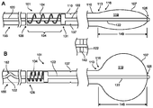
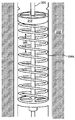
도 1A 및 도 1B는 확장된 상태에서 벌룬을 가압시키는 스프링 부재를 지니는 벌룬 카테터의 일례의 대표적인 부분을 나타낸 도면;
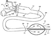
도 2는 도 1A 및 도 1B에 도시된 벌룬 카테터의 일례의 추가적인 상세를 나타낸 도면;
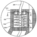
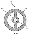
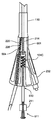
도 3a 내지 도 3d는 도 2에 도시된 카테터의 근위 단부에 배치될 수 있는 스프링 부재의 일 구현예의 추가적인 상세를 나타낸 도면;
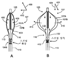
도 4A 및 도 4B는 도 2에 도시된 카테터의 원위 단부에 배치될 수 있는 스프링 부재의 다른 구현예의 추가적인 상세를 나타낸 도면;
도 5는 도 2에 도시된 카테터의 근위 단부에 배치될 수 있는 스프링 부재의 또 다른 구현예의 추가적인 상세를 나타낸 도면.1A and 1B show representative portions of an example of a balloon catheter with a spring member that presses the balloon in an expanded state;
2 shows further details of one example of the balloon catheter shown in FIGS. 1A and 1B;
3A-3D show additional details of one embodiment of a spring member that may be disposed at the proximal end of the catheter shown in FIG. 2;
4A and 4B show further details of another embodiment of a spring member that may be disposed at the distal end of the catheter shown in FIG. 2;
FIG. 5 shows further details of another embodiment of a spring member that may be disposed at the proximal end of the catheter shown in FIG. 2.
벌룬 카테터의 벌룬 부분을 수축시켜 시술 후에 환자로부터의 그의 회수를 가능하게 돕기 위하여, 상기 벌룬 카테터는 확장된 상태에서 벌룬을 가압시키는 스프링 부재를 포함할 수 있다. 이러한 확장된 상태에서, 상기 벌룬 재료는 그의 팽창전 직경보다 큰 직경까지 수축되거나 주름지는 경향은 덜해질 수 있다. 상기 스프링 부재는, 예를 들어, 치료 동안 환자의 외부에 남게 되는 카테터 샤프트의 근위 단부, 또는 벌룬에 가까운 카테터 샤프트의 원위 단부 등과 같은 카테터 내의 각종 위치에 배치될 수 있다. 벌룬을 확장된 상태에서 가압시키기 위하여, 스프링 부재는 벌룬의 원위 단부 내로 연장되어 해당 원위 단부에 고정되는 세장형 부재에 말단-지향적 힘을 작용시킬 수 있다. 몇몇 실시형태에서, 상기 세장형 부재는 가이드와이어 루멘이다. 다른 구현예에서, 상기 세장형 부재는 액체 혹은 기체를 전달하거나 벌룬 내부의 챔버로부터 액체 혹은 기체를 회수하기 위한 공급 혹은 배출 루멘 등과 같은 다른 유형의 루멘이다.In order to deflate the balloon portion of the balloon catheter to facilitate its recovery from the patient after the procedure, the balloon catheter may include a spring member that presses the balloon in an expanded state. In this expanded state, the balloon material may have less tendency to shrink or crimp to a diameter larger than its pre-expansion diameter. The spring member may be disposed at various locations within the catheter, such as, for example, the proximal end of the catheter shaft that remains outside of the patient during treatment, or the distal end of the catheter shaft close to the balloon. To press the balloon in the expanded state, the spring member can extend into the distal end of the balloon and exert an end-directed force on the elongate member that is secured to the distal end. In some embodiments, the elongate member is a guidewire lumen. In other embodiments, the elongate member is another type of lumen, such as a supply or discharge lumen or the like for delivering liquid or gas or for recovering liquid or gas from a chamber inside the balloon.
도 1A 및 도 1B는 확장된 상태에서 벌룬(107)을 가압시키는 - 예를 들어, 시술 후 환자로부터 벌룬(107)의 수축 및 회수를 용이하게 하기 위하여 - 스프링 부재를 지니는 벌룬 카테터(101)의 일례의 대표적인 부분을 나타내고 있다. 가압은 벌룬(107)을 확장시키는 경향이 있는 힘을 작용시키는 것을 포함할 수 있다. 즉, 가압력(bias force)은 다른 힘(예를 들어, 팽창된 경우 벌룬의 표면장력 등)에 의해 극복될 수 있지만, 이러한 다른 힘이 없다면, 상기 가압력은 벌룬을 확장시켜, 그의 팽창전 직경보다 큰 직경을 지니거나 주름지는 것을 방지하는 경향이 있을 것이다. 예시의 목적을 위하여, 도 1A는 벌룬(107)이 수축된 경우 카테터(101)의 대표적인 부분을 나타내고 있고, 도 1B는 벌룬(107)이 팽창된 경우 카테터(101)의 대표적인 부분을 나타내고 있다.1A and 1B illustrate the
본 명세서에 기재된 스프링 부재(104)는 환자 내부의 치료 부위에 요법을 전달하는 데 이용될 수 있는 소정 종류의 벌룬 카테터 내에 포함될 수 있다. 예를 들어, 스프링 부재(104)는 환자 내부의 조직을 냉동 혹은 동결시키기 위한 냉동 요법 카테터 내에 포함될 수 있다. 다른 예로서, 스프링 부재(104)는 환자 내부의 치료 부위에 RF 에너지를 전달하는 데 이용될 수 있는 것 등과 같은 무선주파수(RF) 벌룬 카테터 내에 포함될 수 있다. 또 다른 예로서, 스프링 부재(104)는 환자 내부의 부위에 스텐트 등과 같은 의료 기구를 전달하도록 구성된 벌룬 카테터 내에 포함될 수 있다. 다른 유형의 벌룬 카테터도 스프링 부재(104)의 내포로부터 마찬가지로 유익을 얻을 수 있다.The
일례에 도시된 바와 같이, 상기 벌룬 카테터(101)는 카테터 샤프트(110) 및 해당 카테터 샤프트(110)의 원위 단부(113)에 배치된 팽창성 벌룬(107)을 구비한다. 더욱 구체적으로, 팽창성 벌룬(107)의 근위 단부(116)는 카테터 샤프트(110)의 원위 단부(113)에 고정되어 있다. 내부 챔버(119)는 벌룬(107)의 벽이나 표피에 의해 규정될 수 있다. 벌룬(107)은 도 1A 및 도 1B에 있어서 단일 벽으로서 도시되어 있지만, 몇몇 구현예에서, 카테터(101)는 2개의 개별의 벌룬을 이용할 수 있다 - 그 중 하나는 제1벌룬이 환자 내부에서 파열되거나 그렇지 않으면 실패한 경우 제1벌룬 내부에 있는 제제로부터 환자를 보호하기 위한 안전 벌룬으로서 기능할 수 있다. 안전 벌룬을 내포하는 구현예의 추가적인 상세는 이하에 제공된다.As shown in one example, the
세장형 부재(122)는 팽창성 벌룬(107) 내부에 배치될 수 있다. 몇몇 구현예에서, 도시된 바와 같이, 세장형 부재(122)는 팽창성 벌룬(107)의 원위 단부(125)에 고정되어 있다. 이 예에서, 세장형 부재(122)는 카테터 샤프트(110)와는 분리되어 해당 샤프트 내에서 병진이동할 수 있다. 세장형 부재(122)의 다른 부분은 스프링 부재(104)에 결합되어 있다.The
스프링 부재(104)의 일 단부(128)는 고정되어 있을 수 있다. 도 1A 및 도 1B의 예에서, 스프링 부재(104)는 카테터 샤프트(110)에 고정되어 있다. 다른 예(예컨대, 도 3a 또는 도 5에 도시된 예들)에 있어서, 스프링 부재(104)의 제1단부(128)는 카테터(101)의 다른 요소에 고정될 수 있다. 스프링 부재(104)의 제2단부(131)는 세장형 부재(122)에 결합될 수 있지만, 다르게는 스프링 부재(104)에 인접하여 해당 스프링 부재를 둘러싸는 채널(134) 내에서 병진이동할 수도 있다. 몇몇 구현예에서, 채널(134)은 카테터 샤프트(110) 자체에 의해 형성되고, 또한 스프링 부재(104)를, 도 1A에 도시된 바와 같이, 그의 가장 확장된 상태에서도, 어느 정도까지 압축된 상태로 유지할 수 있는 유지 부재(137)에 의해 더욱 둘러싸일 수 있다. 다른 구현예에서, 유지 부재(137)는 (예컨대, 벌룬(107)의 실패 없이) 스프링 부재(104)와 통상 접촉하지 않는다. 몇몇 구현예에서, 채널(134) 내에 스프링 부재(104)를 센터링하는 것을 돕거나 또는 스프링 부재(104)를 세장형 부재(122)에 결합시키기 위하여, 원반(140) 혹은 기타 가이드가 포함될 수도 있다. 이러한 원반(140)은 이하에 더욱 상세히 설명한다.One
벌룬(107)의 원위 단부(125) 및 스프링 부재(104)의 제2단부(131)에 결합된 세장형 부재(122)에 의해, 스프링 부재(104)는 세장형 부재(122)를 통해서 벌룬(107)에 말단-지향적 길이방향 힘을 인가할 수 있다. 그래서, 스프링 부재(104)의 압축력의 대부분이 벌룬(107)에 인가되고, 임의의 유지 부재(예컨대, 유지 부재(137))는 스프링 부재에 통상 접촉하지 않도록 위치결정될 수 있다. 게다가, 세장형 부재(122)는 (예컨대, 특히 길이 방향에서 비압축성이거나, 최소 압축성이거나 강고한) 실질적으로 비압축성 재료로 만들어져 있을 수 있다. 즉, 세장형 부재(122)는 스프링 부재(104) 부근에 있는 세장형 부재(122)의 병진이동이 실질적으로 동등한 정도(예컨대, 소정의 비교적 작은 마진 내, 예를 들어, 10%, 5%, 0.5% 등 내)의 벌룬(107) 내부로의 세장형 부재(122)의 대응하는 병진이동을 일으키도록 구성되어 있을 수 있다. 적절한 실질적으로 비압축성 재료로는, 예를 들어, 꼰 재료(예컨대, 금속 꼬임부가 매립된 플라스틱 관) 혹은 하이포튜브(예컨대, 강철 하이포튜브) 등을 들 수 있다.By
스프링 부재(104)로부터 세장형 부재(122)를 통해 벌룬(107)으로 힘의 전달을 더욱 용이하게 하기 위하여, 카테터 샤프트(110)는 유지 부재(143) 등과 같은 하나 이상의 유지 부재를 포함할 수 있다. 몇몇 구현예에서, 유지 부재(143)는 세장형 부재(122)가 카테터 샤프트(110)에 대해서 병진이동할 수 있게 하는 한편, 세장형 부재(122)와 카테터 샤프트(110)를 실질적으로 (예를 들어, 비교적 작은 마진, 예컨대, 25%, 10%, 5%, 0.5% 등 내) 공축 관계를 유지할 수 있게 한다.To further facilitate the transfer of force from the
도 1A 및 도 1B는, 함께 볼 경우, 벌룬(107)의 상태(예컨대, 벌룬(107)이 팽창되는지 혹은 수축되는지의 여부)와 스프링 부재(104)의 상태(예컨대, 스프링 부재(104)가 어느 정도까지 압축되는지의 여부) 간의 상호작용을 예시하고 있다. 구체적으로는, 도 1B를 참조하면, 벌룬(107)의 팽창은, 도 1B의 일례에 도시된 바와 같이, 벌룬이 실질적으로 구형상으로 팽창하는 것으로 가정할 경우, 벌룬(107)의 원위 영역(125)과 근위 영역(116) 간의 거리(146)가 해당 벌룬(107)의 직경과 거의 동일하게 되게 한다. 이 거리(146)는, 벌룬이 도 1A에 도시된 바와 같이 팽창되지 않은 경우 벌룬(107)의 원위 영역(125)과 근위 영역(116) 간의 거리(149)보다 비교적 작다. 벌룬(107)이 도 1A의 일례에 묘사된 바와 같이 팽창되지 않은 경우, 스프링 부재(104)는 그의 가장 확장된 상태에 있고; 벌룬(107)이 도 1B에 묘사된 바와 같이 팽창된 경우, 스프링 부재(104)는 임의의 초기의 압축상태보다 더욱 압축될 수 있다.1A and 1B show that when viewed together, the state of the balloon 107 (eg, whether the
스프링 부재(104)의 근위 측 상의 세장형 부재(122)의 병진이동을 수용하기 위하여, 일부의 이완부(152)가 세장형 부재(122) 내에 제공될 수 있다. 즉, 카테터 샤프트(110)의 근위 단부(155)에서 카테터 샤프트(110)에 고정된 세장형 부재(122)를 위하여, 세장형 부재(122)의 여분의 길이(152)가 근위 단부(155)와 스프링 부재(104) 사이에 배치되어, 거리(146)와 거리(149) 사이의 차이를 수용할 수 있게 한다.In order to accommodate translation of the
이하에 더욱 상세히 설명하는 바와 같이, 세장형 부재(122) 자체는 벌룬(107)을 가압시키는 것에 부가해서 상이한 목적을 제공할 수 있다. 예를 들어, 몇몇 구현예에서, 세장형 부재(122)는 가이드와이어 루멘이다. 다른 구현예에서, 세장형 부재(122)는 내부 챔버(119)에 액체 혹은 기체를 제공하기 위한 공급 루멘이다. 또 다른 구현예에서, 세장형 부재(122)는 내부 챔버(119)로부터 액체 혹은 기체를 추출하기 위한 배출 루멘일 수 있다. 세장형 부재(122) 및 카테터(101)의 추가의 상세는 일반적으로 이하에 도 2를 참조하여 제공된다.As will be explained in more detail below, the
도 2는 도 1A 및 도 1B에 도시된 카테터(101)의 일례의 추가적인 상세를 예시하고 있다. 도 2의 예에 도시된 바와 같이, 상기 벌룬 카테터(101)는 전달 외피(202) 내에 배치되어 있다. 다른 구현예에서, 전달 외피(202)는 포함되어 있지 않다. 전달 외피를 구비한 몇몇 구현예에서, 전달 외피(202)는 초기에 환자 내부에 놓일 수 있고 이어서 벌룬 카테터(101) 등과 같은 기타의 의료 기구용 도관으로서 이용될 수 있는 중공관이다. 수개의 카테터(예컨대, 상이한 크기 혹은 특징의 카테터 혹은 상이한 기능을 지니는 카테터)가 이용될 수 있는 시술을 위하여, 전달 외피(202)는 각종 의료 기구가 통과되는 환자의 체내 기관 및 체강을 보호할 수 있다. 또한, 전달 외피(202)는 의사 혹은 기타 기술자에 의해 치료 부위로 기타 의료 기구의 보다 용이한 통과를 용이하게 할 수 있다.FIG. 2 illustrates additional details of one example of the
전달 외피(202)는 조종가능할 수 있고, 이것은 구체적인 특성을 지닐 수 있다. 예를 들어, 전달 외피는 8.5 Fr(French), 10 Fr, 11 Fr 등과 같은 다양한 직경; 60㎝, 65㎝, 71㎝, 78㎝, 90㎝ 등과 같은 다양한 길이로 이용가능하고 또한 예를 들어, 15°만곡(curve), 55°만곡, 짧은 120°만곡, 긴 120°만곡 등과 같은 다양한 형태로 편의되는 원위 단부를 지니도록 이용될 수 있다. 상이한 전달 외피는 상이한 시술을 위해 구성될 수 있다. 예를 들어, 하나의 편의된 만곡을 지니는 전달 외피는 심방 세동을 치료하기 위하여 환자의 폐정맥에 냉동 벌론을 안내하는 데 특히 효과적일 수 있는 한편, 상이한 편의된 곡률을 지니는 전달 외피는 스텐트-전달 벌룬을 안내하는 데 특히 효과적일 수 있다.The
몇몇 구현예에서, 도 2에 도시된 바와 같이, 전달 외피(202)의 원위 팁(distal tip)(205)은 환자의 혈관을 통한 해당 팁(205)의 통과를 용이하게 하도록 혹은 환자의 조직막(예컨대, 심방 세동을 치료하는 시술 동안 중격벽)의 횡단을 용이하게 하기 위하여 다소 테이퍼 형상으로 되어 있다. 근위 단부(208)는 전달 외피(202)에 배치된 것으로 도시된 벌룬 카테터(101) 등과 같은 기타 의료 기구를 더욱 용이하게 수용하도록 테이퍼 형상으로 되어 있을 수 있다.In some embodiments, as shown in FIG. 2, the
도 2의 예에서, 벌룬 카테터(101)는 가이드와이어 루멘(214) 내부에 배치된 가이드와이어(211)를 지니는 와이어-경유 냉동요법 벌룬 카테터이다. 독자는 기타 유형의 벌룬 카테터가 벌룬(107)에 말단-지향적 힘을 인가하는 데 스프링 부재(도 2에는 도시 생략)를 이용할 수 있음을 이해할 수 있을 것이다. 예를 들어, 다른 구현예에서, 벌룬 카테터(101)는 가이드와이어(121)를 이용하지 않을 수도 있다. 다른 예로서, 다른 구현예에서, 벌룬 카테터(101)는 냉각제를 이용해서 열을 추출하는 것에 의하기보다 오히려 RF 에너지를 이용해서 조직을 리모델링하는 고주파(RF) 절제 카테터일 수도 있었다.In the example of FIG. 2, the
도 2에 도시된 냉동요법 벌룬 카테터(101)의 일례에 있어서, 냉동 유체는, 외부 공급원(217)으로부터 공급 루멘(220)을 통해서 벌룬(107)으로 전달될 수 있고, 또, 이것은 냉각 기구(223)(예컨대, 소정의 냉각제가 방출되어 주울-톰슨 효과(Joule-Thomson effect)에 의해 벌룬(107)을 냉각시키는 액체-대-기체 상 변화를 받을 수 있는 각종 오리피스를 지니는 공급 루멘(220)의 코일 부분)를 통해서 내부 챔버(119) 내부로 방출될 수 있다. 방출되고 있는 냉동 유체에 기인해서 챔버(119) 내부의 상을 변화시키는 기체는 별도의 배출 루멘(226)를 통해 배출될 수 있다. 특히, 예를 들어, 몇몇 구현예에서, 기체는 배출 루멘(226)을 통해서 외부 진공 펌프(229)로 배출된다.In one example of the
카테터(101)의 외부 장비, 예컨대, 냉각제의 공급원(217) 혹은 진공 펌프(229)에의 결합을 용이하게 하기 위하여, 카테터(101)는 다수의 결합 부재(235A), (235B)를 구비한 포트 요소(232)를 포함할 수 있다. 결합 부재(235A), (235B)는, 몇몇 구현예에서, 루멘(220), (226)의 (예컨대, 의료용 관을 이용해서) 외부 장비에의 접속을 용이하게 하는 접속기(예컨대, 공업-규격 의료 접속기, 전용 의료 접속기, 기타 접속기 등)를 이용한 카테터 샤프트 내에 있는 루멘(예컨대, 공급 루멘(220) 및 배출 루멘(226))을 종결시킬 수 있다. 일례에 도시된 바와 같이, 포트 요소(232)는 또한 가이드와이어 루멘(214) 및 대응하는 가이드와이어(211)에의 접근을 제공할 수 있다. 도 2에 도시된 바와 같이, 포트 요소(232)는 단지 예에 불과하다. 기타 접속 및 구성(예컨대, 압력 센서(들), 전기 센서(들), 다수의 진공 포트 등용의 접속)도 가능하며 상정될 수 있다.In order to facilitate coupling of the
위에서 언급되고 도 2에 도시된 바와 같이, 2개의 개별의 벌룬(107A), (107B)이 카테터 샤프트(110)의 단부 상에 배치될 수 있다. 벌룬(107A), (107B)은 함께 팽창/수축될 수 있다. 몇몇 구현예에서, 제2벌룬(107B)은 안전 벌룬(107B)으로서 기능한다. 즉, 벌룬(107A)이 파열되거나 그렇지 않으면 실패하는 사고에 있어서, 안전 벌룬(107B)은 내부 챔버(119) 내의 제제(예컨대, 냉각제)가 환자의 내부 체조직과 직접 접촉하는 것을 방지할 수 있고 또한 마찬가지로 체조직과 체액이 내부 챔버(119)에 도달하는 것을 방지할 수 있다. 몇몇 구현예에서, 개별의 진공 루멘(도시 생략)이 벌룬(107A)과 (107B) 사이에 설치되어, 벌룬(107A)과 (107B) 사이서 일정한 진공을 인가하는 데 이용될 수 있다. 내측 벌룬(107A)이 파열되는 사고에 있어서, 일정한 진공력이 내부 챔버(119) 내부의 어떠한 액체 및/또는 기체를 계속 배기시켜 이것이 환자 내부의 조직과 직접 접촉하는 것을 방지할 수 있다. 내측 벌룬(107A) 혹은 외측 벌룬(107B)이 파열되면, 벌룬(107A)과 (107B) 사이의 진공력을 모니터링하는 센서가 변화를 검출할 수 있어, 경고를 울리거나 교정 행위를 취하거나 할 수 있게 된다.As mentioned above and shown in FIG. 2, two
위에서 언급된 바와 같이, 스프링 부재(104)(도 2에 도시 생략)는 카테터(101) 내의 각종 위치에 배치될 수 있다. 예를 들어, 몇몇 구현예에서, 도 3a 내지 도 3d를 참조하여 설명된 바와 같이, 스프링 부재(104A)는 포트 요소(232) 내에 배치되어 있다. 다른 구현예에서, 도 4를 참조하여 설명된 바와 같이, 스프링 부재(104B)는, 벌룬(107)의 근위 단부(116)가 (예컨대, 10㎝, 5㎝, 1㎝ 등과 같은 짧은 거리 내에 또는 카테터 샤프트의 전체 길이의 작은 비율 내, 예컨대, 해당 전체 길이의 20%, 10%, 2% 등 내에) 고정되는 원위 단부(113)(도 1A 참조)에 근접하여 카테터 샤프트(110) 내에 배치된다. 스프링 부재(104)는 또한, 예를 들어, 공급 루멘(예컨대, 도 3a 내지 도 3d 및 도 4A 내지 도 4B를 참조하여 설명됨), 배출 루멘, 가이드와이어 루멘(예컨대, 도 5를 참조하여 설명된 것), 또는 기타 카테터 구조(예컨대, 다른 루멘 혹은 독립형 구조) 등과 같은 각종 루멘에 말단-지향적 길이방향 힘을 제공하는 데 이용될 수 있다.As mentioned above, the spring member 104 (not shown in FIG. 2) may be disposed at various positions within the
도 3a는 스프링 부재(104A)가 포트 요소(232) 내에 설치되어 있는 하나의 예시적인 구현예의 일부 절개도이다. 구체적으로는, 이 예에 묘사된 바와 같이, 스프링 부재(104A)는 예시적인 냉동요법 카테터(101)의 공급 루멘(220)에 결합되어 있다. 더욱 구체적으로는, 스프링 부재(104A)의 제1단부(128A)는 포트 요소(232)에 고정되고, 스프링 부재(104A)의 제2단부(131A)는 공급 루멘(220) 상에 말단-지향적 길이방향 힘을 작용시키기 위하여 공급 루멘(220)에 결합되어 있다. 이 예에서는, 벌룬(107)이 도 3A에는 도시되어 있지 않지만, 공급 루멘(220)은 벌룬(107)의 원위 단부(125)에 고정될 수 있고, 또한 다르게는 카테터 샤프트(110) 내에서 병진이동할 수 있다.3A is a partial cutaway view of one exemplary embodiment in which
이 예에서 묘사된 바와 같이, 배출 공간(303)이 카테터 샤프트(110) 내의 배출 루멘(226)에 결합되고, 포트 요소(232) 내에서는, 배출 공간(303)이 (예컨대, 공급 루멘(220) 내의 이완부(306)에 의해 초래된 소정량의 편차 내에서) 공급 루멘(220)과 대략 공축이다. 전후 관계를 위하여, 가이드와이어 루멘(214)은 제2배출로(309)를 따라 포트 요소(232) 내에 도시되어 있다. 몇몇 구현예에서, 제2배출로(309)는 도 2에 도시된 벌룬(107A), (107B) 사이의 전술한 공간을 배기시키는 루멘(도시 생략)에 결합되어 있다. 도 3a에 도시된 바와 같이, 필터(307)는 배출 공간(303) 및/또는 공급 루멘(220)을 외부 장비에 결합시키기 위한 결합 부재 내에 포함되어 있을 수 있다. 본 구현예에서의 스프링 부재(104A)의 추가적인 상세는 도 3b 내지 도 3d를 참조하여 이하에 제공된다.As depicted in this example, the discharge space 303 is coupled to the
도 3b는 도 3a에 도시된 스프링 부재(104A)의 추가적인 상세를 예시하고 있다. 도시된 바와 같이, 스프링 부재(104A)는 제1단부(128A)에서 포트 요소(232)에 고정되어 있다. 제2단부(131A)는 원반(312)에 고정되어, 포트 요소(232) 내에 형성된 채널(134A) 내에 병진이동할 수 있다. 원반(312)은 공급 루멘(220)에 고정되어 있으므로, 원반(312)은 (예컨대, 스프링 부재(104A)에 의해 작용된 힘 또는 (벌룬(107)이 팽창된 경우) 벌룬(107)으로부터 공급 루멘(220)으로 전달되는 힘에 응답하여) 채널(134A) 내로 병진이동한다. 도 3c를 참조하여 설명하는 바와 같이, 스프링 부재(104A) 내에 있으면서 공급 루멘(220) 둘레의 공간은 배출용의 도관(305)으로서 역할할 수 있다.FIG. 3B illustrates additional details of the
도 3c는 원반(312)의 추가적인 예의 상세를 예시하고 있다. 도시된 예에서, 원반(312)은 원형이므로, 포트 요소(232)에 형성된 원통형 채널(134A) 내에 병진이동할 수 있다. 개구부(315)는 공급 루멘(220)을 수용하여 유지하도록 제공되며, 추가의 개구부(318)는 배기가 스프링 부재(104A)를 통과할 수 있게 하도록 제공된다. 도 3d는 스프링 부재(104A), 원반(312), 공급 루멘(220) 및 배출 도관(305)을 더욱 예시한 사시도이다.3C illustrates the details of a further example of
도 4A 및 도 4B는 벌룬(107)의 근위 단부(116)가 (예컨대, 10㎝, 5㎝, 1㎝ 등의 짧은 거리 내에서 또는 카테터 샤프트의 전체 길이의 작은 비율 내에서, 예컨대 해당 전체 길이의 20%, 10%, 2% 등 내에서) 고정되는 원위 단부(113)에 근접하여 스프링 부재(104B)가 카테터 샤프트(110) 내에 배치되어 있는 다른 구현예를 예시하고 있다.4A and 4B show that the
도 4A는 스프링이 확장되어 있는 상황에서 비팽창 상태의 벌룬(107)(더욱 자세하게는, 벌룬(107A), (107B), 여기서는 간략화하기 위하여 벌룬(107)이라 간단히 지칭됨)을 예시하고 있다. 스프링 부재(104B)에 의해 제공된 말단-지향적 힘(403)은 확장된 상태의 가압된 벌룬(107)에 의해 제공된다. 특히, 벌룬(107)을 말단으로 가압함으로써 안쪽 힘(406)을 벌룬의 벽들에 인가시킨다. 더욱 상세하게는, 세장형 부재(122)에 대한 힘은 접선힘(409)으로서 벌룬(107)의 벽들에 전달된다. 벌룬의 벽들이 길이방향 힘(예컨대, 벌룬의 벽들이 도 4A에 약간 굵게 도시됨)과 평행하지 않은 정도까지, 접선힘(409)이 벌룬 벽들을 안쪽으로 당기는 방사상 성분(410)을 지닌다.4A illustrates the balloon 107 (more specifically, the
도 4B는 도 4A에서의 그의 상태보다 큰 정도로 스프링 부재(104B)가 압축된 상황에서 팽창된 상태의 벌룬(107)을 예시하고 있다. 특히, 벌룬(107)을 팽창시키는 내부 챔버(119) 내의 압력은 벌룬의 벽들에 바깥쪽 힘(415)을 인가한다. 이 바깥쪽 힘(415)은 접선힘(421)으로서 벌룬(107)의 벽들에 전달되고, 도시된 바와 같이, 접선힘(421)은 스프링 부재(104B)에 의해 제공된 가압력에 대항하는 길이방향 혹은 축방향 성분(424)을 지녀, 도시된 바와 같이 스프링 부재(104B)를 압축시킨다.4B illustrates the
도 4A 및 도 4B의 예에서의 스프링 부재(104B)는, 예를 들어, 가이드와이어 루멘(만약 존재한다면)에 혹은 공급 루멘에 결합될 수 있다. 대안적으로, 스프링 부재(104B)는 확장된 상태에서 벌룬의 원위 단부(125)를 가압하도록 구체적으로 구성된 봉 혹은 기타 구조 요소 등과 같은 독립형 벌룬 구조에 결합되어 있을 수 있다.
스프링 부재(104B)는 도 3b 내지 도 3d에 도시된 바와 같은 유사한 구성을 지닐 수 있고, 스프링 부재를 통과하거나 인접한 다른 카테터 및 필요한 루멘을 수용하도록 적절한 변형이 가능하다. 특히, 예를 들어, 추가의 개구부가 스프링 부재(104B)와 연관된 원반(412) 내에 배치될 수 있으므로, 원반(412)에 결합되지 않은 다른 루멘은 스프링 부재(104B)를 통과할 수 있다. 대안적으로, 스프링 부재(104B), 및 해당 스프링 부재(104B)가 점유하는 채널은 그 지점에서 카테터 샤프트(110)보다 작은 직경을 지닐 수 있으므로, 다른 루멘이 스프링 부재(104B)에 인접한 카테터 샤프트(110)를 통과할 수 있다. 특히, 예를 들어, 스프링 부재(104B)가 가이드와이어 루멘에 결합하는 구현예에서, 공급 루멘은 스프링 부재(104B)에 인접하여 라우팅될 수 있고, 배출 채널은 전술한 바와 같이 스프링 부재(104B)를 통과할 수 있다.The
몇몇 구현예에서, 스프링 부재(104B)는 카테터 샤프트(110)의 원위 단부(113) 근방에 배치되는 것이 유리하다. 이러한 구현예에서, 스프링 부재(104B)는, 압축력이 벌룬(107)과 스프링 부재(104B) 사이의 세장형 부재(122)의 길이에 의해 제공되는 말단-지향적 길이방향 힘에 대해서 그만큼의 저항을 극복하지 않아도 될 수 있으므로, 벌룬(107)을 가압하기 위하여 보다 적은 압축력을 필요로 할 수도 있다. 특히, 말단으로 배치된 스프링 부재(104)는, 카테터(101)가 환자 내부에 치료를 제공하기 위하여 이용될 경우 - 특히 카테터(101)가 (예컨대, 환자의 우측 대퇴동맥으로부터 환자의 좌심방에 도달하기 위하여) 구불구불한 혈관 경로를 통해 주행할 경우 제공될 수 있는 세장형 부재(122) 내에 만곡이나 굴곡에 의해 제공되는 그만큼의 저항을 극복할 필요가 없을 수도 있다.In some embodiments, the
스프링 부재(104)가 (예컨대, 도 4A 및 도 4B에 도시된 바와 같이, 카테터 샤프트(110)의 원위 단부(113) 내에 혹은 도 3a에 도시된 바와 같이, 포트 요소(232) 내에) 배치되어 있는 것에 관계없이, 각종 요소의 힘과 장력이 도 4A 및 도 4B에 묘사된 상태를 가능하게 하도록 적절하게 구성되어 있을 수 있다. 즉, 스프링 부재(104B)에 의해 제공된 말단-지향적 힘은, 도 4A에 도시된 바와 같이 벌룬(107)이 팽창되지 않은 경우 벌룬(107)을 확장된 상태로 가압시키는 데 충분할 필요가 있다. 한편, 스프링 부재(104B)는 벌룬(107)이 팽창된 경우(도 4B 참조) 압착되지 않을 수 있도록 경직되지 않을 필요가 있다. 따라서, 재료가 매우 탄성인 벌룬(107)에 대해서, 스프링 부재(104)는 재료가 덜 탄성인 벌룬을 이용한 스프링 부재(104)보다 덜 경직될 수 있다. 다른 힘이 상정되는 것도 가능하다. 예를 들어, 위에서 언급된 바와 같이, 스프링 부재(104A)가 포트 요소(232) 내(또는 카테터 샤프트 내의 다른 더욱 근위의 위치에) 배치되는 구현예에서, 스프링 부재(104A)는 카테터 샤프트(110) 내에의 굴곡이나 꼬임에 의해 제공될 수 있는 세장형 부재(122)의 병진이동에 대한 저항을 극복하기 위하여 더욱 경직성일 필요가 있을 수도 있다.The
도 5는 스프링 부재(104C)가 포트 요소(232) 내에 배치되어 중앙의 가이드와이어 루멘에 결합될 수 있는 다른 구현예를 나타내고 있다. 도 5에 묘사된 바와 같이, 가이드와이어 루멘(214)은 실질적으로 비압축성 재료로 구성될 수 있으므로, 스프링 부재에 의해 제공되는 말단-지향적 힘의 대부분이 벌룬(107)의 원위 말단(125)에 전달되게 된다. 카테터(101)의 기타 루멘 및 구조는 임의의 적절한 방식으로 배치될 수 있다. 도 5의 일례에 도시된 바와 같이, 공급 루멘(220), 배출 루멘(226), 보조 배출 루멘(501), 압력 루멘(504)(예컨대, 벌룬 내부의 압력이 측정될 수 있도록 카테터(101)의 외부에 있는 압력 센서에 결합하기 위한 것) 및 기타 루멘 및 구조는 가이드와이어 루멘(214)에 인접하여 카테터 샤프트(110) 내에서 주행될 수 있다. 예시의 목적을 위하여, 가이드와이어(211) 자체의 근위 단부(507)는 가이드와이어 루멘(214)의 근위 단부(510)로부터 연장되어 도시되어 있다.5 illustrates another embodiment in which the
많은 구현예가 기술되어 있지만, 각종 변형이 이 문서의 정신과 범위로부터 벗어나는 일없이 이루어질 수 있음을 이해할 수 있을 것이다. 특히, 상기 설명은 실시예의 목적을 위하여 냉동 벌룬 카테터를 참조하고 있지만, 여기에 설명된 바와 같은 스프링 부재는 다른 유형의 벌룬 카테터 내에 포함될 수도 있다. 냉동요법 벌룬 카테터는 액체-대-기체 상 변화를 이용해서 냉각되는 주울-톰슨 효과를 이용하는 것으로 설명되어 있지만, 액체 기반 저온카테터도 스프링 부재를 포함할 수 있다. 스프링 부재는 카테터 내의 여러 지점에 배치될 수 있고, 본 명세서에서 설명된 특정 지점은 단지 예시에 불과하다. 몇몇 구현예에서, 스프링 부재는 카테터 외부에 있을 수 있고; 예를 들어, 스프링 부재는 외부 장비를 카테터에 결합하는 접속기 내에 포함될 수 있고 또한 카테터의 루멘 혹은 기타 내부 구조 상에 충돌하여 말단-지향적 힘을 제공할 수도 있었다. 다른 유형의 포트 요소가 이용될 수 있다. 다수의 스프링 부재는 다수의 개소에 이용될 수 있다. 스프링 부재, 루멘 및 기타 카테터 구조는 임의의 적절한 구조를 지닐 수 있고, 또한 임의의 적절한 재료로 제작되어 있을 수 있다. 특히, 예를 들어, 코일 스프링은 예로서 묘사된 것이지만, 독자는 압축될 경우 스프링력을 작용시키는 다른 기구가 스프링 부재로서 이용될 수 있음을 이해할 수 있을 것이다. 따라서, 다른 구현예도 이하의 특허청구범위의 범주 내이다.While many embodiments have been described, it will be understood that various modifications may be made without departing from the spirit and scope of this document. In particular, while the above description refers to a frozen balloon catheter for the purposes of the embodiment, a spring member as described herein may be included in other types of balloon catheter. Cryotherapy balloon catheters have been described to utilize the Joule-Thomson effect, which is cooled using liquid-to-gas phase changes, but liquid-based cryogenic catheters may also include spring elements. The spring member may be disposed at various points in the catheter, and the specific points described herein are merely examples. In some embodiments, the spring member can be external to the catheter; For example, the spring member could be included in a connector that couples external equipment to the catheter and could also impinge on the lumen or other internal structure of the catheter to provide end-directed force. Other types of port elements can be used. Many spring members can be used in many places. The spring member, lumens and other catheter structures can have any suitable structure and can also be made of any suitable material. In particular, for example, the coil spring is depicted by way of example, but the reader will appreciate that other mechanisms that exert a spring force when compressed can be used as the spring member. Accordingly, other embodiments are within the scope of the following claims.
Claims (22)
상기 카테터 샤프트의 단부에 고정된 근위 단부를 지닌 팽창성 벌룬;
상기 카테터 샤프트와는 분리되어 해당 카테터 샤프트 내부에 배치되고, 상기 팽창성 벌룬의 내부 챔버 속으로 연장되어 상기 팽창성 벌룬의 원위 단부에 고정되는 세장형 부재(elongate member); 및
상기 카테터 샤프트에 대해서 상기 세장형 부재 상에 말단-지향적 길이방향 힘(distally-oriented longitudinal force)을 작용시키는 스프링 부재를 포함하되,
상기 말단-지향적 길이방향 힘은 상기 팽창성 벌룬을 상기 카테터 샤프트의 단부로부터 멀리 떨어져서 확장된 위치로 가압(bias)시키는 것인 벌룬 카테터(balloon catheter).Catheter shaft;
An inflatable balloon having a proximal end fixed to an end of the catheter shaft;
An elongate member separate from the catheter shaft and disposed within the catheter shaft and extending into the inner chamber of the inflatable balloon and fixed to the distal end of the inflatable balloon; And
A spring member for exerting a distally-oriented longitudinal force on the elongate member against the catheter shaft,
And the end-oriented longitudinal force biases the inflatable balloon to an extended position away from an end of the catheter shaft.
치료 시술 전후에 상기 팽창성 벌룬을 둘러싸도록 구성된, 상기 카테터 샤프트를 둘러싸고 있는 외피;
상기 카테터 샤프트와는 분리되어 해당 카테터 샤프트 내부에 배치되고, 상기 팽창성 벌룬의 내부 챔버 속으로 연장되어 상기 팽창성 벌룬의 원위 단부에 고정되는 세장형 부재; 및
상기 카테터 샤프트에 대해서 상기 세장형 부재 상에 말단-지향적 길이방향 힘을 작용시키는 스프링 부재를 포함하되,
상기 팽창성 벌룬은 치료 시술 동안 상기 외피 바깥쪽의 치료 부위로 이동되어 팽창되도록 구성되어 있고, 상기 말단-지향적 길이방향 힘은, 치료 시술 후에 상기 외피 내로의 상기 팽창성 벌룬의 수축과 회수를 용이하게 하는 방식으로, 상기 카테터 샤프트의 단부로부터 멀리 떨어져서 확장된 위치에서 상기 팽창성 벌룬을 가압시키는 것인 벌룬 카테터.A catheter shaft having a distal end fixed to the proximal end of the inflatable balloon;
An envelope surrounding the catheter shaft, configured to surround the inflatable balloon before and after the treatment procedure;
An elongate member separate from the catheter shaft and disposed within the catheter shaft, extending into an inner chamber of the inflatable balloon and fixed to the distal end of the inflatable balloon; And
A spring member for exerting an end-oriented longitudinal force on the elongate member against the catheter shaft,
The inflatable balloon is configured to move and expand out of the envelope to the treatment site during the treatment procedure, and the end-oriented longitudinal force facilitates contraction and recovery of the inflatable balloon into the envelope after the treatment procedure. And in such a manner as to pressurize the inflatable balloon in an extended position away from an end of the catheter shaft.
상기 외피 밖으로 상기 벌룬을 전진시켜, 스프링 부재를 초기의 압축된 상태보다 큰 정도로 압축시키는 방식으로 상기 벌룬을 팽창시키고, 해당 벌룬에 의해 치료 부위에 요법을 전달하는 단계;
상기 벌룬을 수축시키는 단계; 및
상기 스프링 부재가 상기 수축된 벌룬을 확장된 위치에서 가압시킨 때에 상기 외피 내로 상기 벌룬을 회수하는 단계를 포함하는, 환자에게 요법을 제공하는 방법.Introducing a balloon catheter adjacent to the treatment site in an area within the patient, the balloon catheter comprising: a) a catheter shaft; b) an inflatable balloon having a proximal end fixed to an end of the catheter shaft; c) a sheath surrounding the catheter shaft and initially surrounding the inflatable balloon; d) an elongate member separate from the catheter shaft, disposed within the catheter shaft, extending into the inner chamber of the inflatable balloon and fixed to the distal end of the inflatable balloon; And e) a spring member for exerting an end-oriented longitudinal force on the elongate member against the catheter shaft to press the inflatable balloon to an expanded position away from an end of the catheter shaft. Introduction step of;
Advancing the balloon out of the envelope, inflating the balloon in a manner that compresses the spring member to a greater extent than the initial compressed state, and delivering therapy to the treatment site by the balloon;
Retracting the balloon; And
Recovering the balloon into the shell when the spring member presses the retracted balloon in the extended position.
Applications Claiming Priority (2)
| Application Number | Priority Date | Filing Date | Title |
|---|---|---|---|
| US9902108P | 2008-09-22 | 2008-09-22 | |
| US61/099,021 | 2008-09-22 |
Publications (1)
| Publication Number | Publication Date |
|---|---|
| KR20110063551A true KR20110063551A (en) | 2011-06-10 |
Family
ID=41259982
Family Applications (1)
| Application Number | Title | Priority Date | Filing Date |
|---|---|---|---|
| KR1020117008994A KR20110063551A (en) | 2008-09-22 | 2009-09-18 | Biasing a catheter balloon |
Country Status (6)
| Country | Link |
|---|---|
| US (1) | US8333757B2 (en) |
| EP (1) | EP2334365B1 (en) |
| JP (1) | JP5577343B2 (en) |
| KR (1) | KR20110063551A (en) |
| CA (1) | CA2737272A1 (en) |
| WO (1) | WO2010033785A1 (en) |
Families Citing this family (67)
| Publication number | Priority date | Publication date | Assignee | Title |
|---|---|---|---|---|
| US7780723B2 (en) | 2005-06-13 | 2010-08-24 | Edwards Lifesciences Corporation | Heart valve delivery system |
| US9061119B2 (en) | 2008-05-09 | 2015-06-23 | Edwards Lifesciences Corporation | Low profile delivery system for transcatheter heart valve |
| US8652202B2 (en) | 2008-08-22 | 2014-02-18 | Edwards Lifesciences Corporation | Prosthetic heart valve and delivery apparatus |
| US10695126B2 (en) | 2008-10-06 | 2020-06-30 | Santa Anna Tech Llc | Catheter with a double balloon structure to generate and apply a heated ablative zone to tissue |
| US8465481B2 (en) | 2008-10-20 | 2013-06-18 | Boston Scientific Scimed, Inc. | Providing cryotherapy with a balloon catheter having a non-uniform thermal profile |
| WO2010093603A1 (en) | 2009-02-11 | 2010-08-19 | Boston Scientific Scimed, Inc. | Insulated ablation catheter devices and methods of use |
| US20100274189A1 (en) * | 2009-04-22 | 2010-10-28 | Pressure Products Medical Supplies Inc. | Balloon catheter and method of manufacture of the same |
| US8827952B2 (en) * | 2010-12-06 | 2014-09-09 | Boston Scientific Scimed, Inc. | Biasing mechanism for a balloon catheter |
| US8790300B2 (en) | 2010-12-06 | 2014-07-29 | Boston Scientific Scimed, Inc. | Dual balloon catheter |
| US9155619B2 (en) | 2011-02-25 | 2015-10-13 | Edwards Lifesciences Corporation | Prosthetic heart valve delivery apparatus |
| US9119716B2 (en) | 2011-07-27 | 2015-09-01 | Edwards Lifesciences Corporation | Delivery systems for prosthetic heart valve |
| US9364637B2 (en) * | 2011-09-06 | 2016-06-14 | Medtronic, Inc. | Transcatheter balloon-assisted mitral valve navigation device and method |
| CN103917185A (en) * | 2011-09-14 | 2014-07-09 | 波士顿科学西美德公司 | Ablation device with ionically conductive balloon |
| EP2755587B1 (en) | 2011-09-14 | 2018-11-21 | Boston Scientific Scimed, Inc. | Ablation device with multiple ablation modes |
| DE102011085616A1 (en) * | 2011-11-02 | 2013-05-02 | Celon Ag Medical Instruments | Electrosurgical probe and electrosurgery device |
| EP2802282A1 (en) | 2012-01-10 | 2014-11-19 | Boston Scientific Scimed, Inc. | Electrophysiology system |
| EP2617456A1 (en) * | 2012-01-19 | 2013-07-24 | VascoMed GmbH | Catheter and catheter system |
| US9168080B2 (en) | 2012-01-27 | 2015-10-27 | Medtronic Cryocath Lp | Balloon catheter |
| US8945015B2 (en) | 2012-01-31 | 2015-02-03 | Koninklijke Philips N.V. | Ablation probe with fluid-based acoustic coupling for ultrasonic tissue imaging and treatment |
| US9883906B2 (en) | 2012-04-22 | 2018-02-06 | Newuro, B.V. | Bladder tissue modification for overactive bladder disorders |
| US10610294B2 (en) | 2012-04-22 | 2020-04-07 | Newuro, B.V. | Devices and methods for transurethral bladder partitioning |
| JP6374374B2 (en) | 2012-04-22 | 2018-08-15 | オムリ ベン−エズラ, | Bladder tissue modification for overactive bladder disorders |
| CN104780859B (en) * | 2012-09-17 | 2017-07-25 | 波士顿科学西美德公司 | Self-positioning electrode system and method for renal regulation |
| US10806830B2 (en) | 2012-10-26 | 2020-10-20 | Urotronic, Inc. | Drug-coated balloon catheters for body lumens |
| US10881839B2 (en) | 2012-10-26 | 2021-01-05 | Urotronic, Inc. | Drug-coated balloon catheters for body lumens |
| US10898700B2 (en) | 2012-10-26 | 2021-01-26 | Urotronic, Inc. | Balloon catheters for body lumens |
| US11504450B2 (en) | 2012-10-26 | 2022-11-22 | Urotronic, Inc. | Drug-coated balloon catheters for body lumens |
| US11938287B2 (en) | 2012-10-26 | 2024-03-26 | Urotronic, Inc. | Drug-coated balloon catheters for body lumens |
| US10850076B2 (en) | 2012-10-26 | 2020-12-01 | Urotronic, Inc. | Balloon catheters for body lumens |
| CZ306454B6 (en) * | 2013-03-28 | 2017-02-01 | Ella-Cs, S.R.O. | A catheter for inserting plastic stents |
| CA2954479C (en) * | 2014-07-28 | 2023-09-05 | Smart Medical Systems Ltd. | Controlled furling balloon assembly |
| US10524684B2 (en) | 2014-10-13 | 2020-01-07 | Boston Scientific Scimed Inc | Tissue diagnosis and treatment using mini-electrodes |
| EP3209234B1 (en) | 2014-10-24 | 2023-11-29 | Boston Scientific Scimed Inc. | Medical devices with a flexible electrode assembly coupled to an ablation tip |
| EP3232969A1 (en) | 2014-12-18 | 2017-10-25 | Boston Scientific Scimed Inc. | Real-time morphology analysis for lesion assessment |
| EP3285820A4 (en) | 2015-04-24 | 2018-12-12 | Urotronic, Inc. | Drug coated balloon catheters for nonvascular strictures |
| US11904072B2 (en) | 2015-04-24 | 2024-02-20 | Urotronic, Inc. | Drug coated balloon catheters for nonvascular strictures |
| US9907610B2 (en) | 2015-05-07 | 2018-03-06 | Biosense Webster (Israel) Ltd. | Spring-loaded balloon |
| US10179046B2 (en) | 2015-08-14 | 2019-01-15 | Edwards Lifesciences Corporation | Gripping and pushing device for medical instrument |
| US11259920B2 (en) | 2015-11-03 | 2022-03-01 | Edwards Lifesciences Corporation | Adapter for prosthesis delivery device and methods of use |
| US10321996B2 (en) | 2015-11-11 | 2019-06-18 | Edwards Lifesciences Corporation | Prosthetic valve delivery apparatus having clutch mechanism |
| US11219746B2 (en) | 2016-03-21 | 2022-01-11 | Edwards Lifesciences Corporation | Multi-direction steerable handles for steering catheters |
| US10799676B2 (en) | 2016-03-21 | 2020-10-13 | Edwards Lifesciences Corporation | Multi-direction steerable handles for steering catheters |
| US10799677B2 (en) | 2016-03-21 | 2020-10-13 | Edwards Lifesciences Corporation | Multi-direction steerable handles for steering catheters |
| US11331140B2 (en) | 2016-05-19 | 2022-05-17 | Aqua Heart, Inc. | Heated vapor ablation systems and methods for treating cardiac conditions |
| US10821272B2 (en) | 2016-11-23 | 2020-11-03 | Biosense Webster (Israel) Ltd. | Double balloon catheter having a lobed inner balloon |
| CN106823111A (en) * | 2016-12-13 | 2017-06-13 | 庞继恩 | A kind of heart intervention treating expansion foley's tube |
| EP3609564A4 (en) * | 2017-04-10 | 2021-01-20 | Flatmed, LLC. | Catheter for guiding body fluid |
| US11224511B2 (en) | 2017-04-18 | 2022-01-18 | Edwards Lifesciences Corporation | Heart valve sealing devices and delivery devices therefor |
| LT3558169T (en) | 2017-04-18 | 2022-02-10 | Edwards Lifesciences Corporation | Heart valve sealing devices and delivery devices therefor |
| US10973634B2 (en) | 2017-04-26 | 2021-04-13 | Edwards Lifesciences Corporation | Delivery apparatus for a prosthetic heart valve |
| US10959846B2 (en) | 2017-05-10 | 2021-03-30 | Edwards Lifesciences Corporation | Mitral valve spacer device |
| JP7167020B2 (en) * | 2017-06-23 | 2022-11-08 | 株式会社グッドマン | balloon catheter |
| US10350395B2 (en) | 2017-06-23 | 2019-07-16 | Cook Medical Technologies Llc | Introducer for lumen support or dilation |
| JP7277389B2 (en) | 2017-06-30 | 2023-05-18 | エドワーズ ライフサイエンシーズ コーポレイション | Docking station for transcatheter valves |
| AU2018291171B2 (en) | 2017-06-30 | 2023-11-30 | Edwards Lifesciences Corporation | Lock and release mechanisms for trans-catheter implantable devices |
| US10857334B2 (en) | 2017-07-12 | 2020-12-08 | Edwards Lifesciences Corporation | Reduced operation force inflator |
| US10806573B2 (en) | 2017-08-22 | 2020-10-20 | Edwards Lifesciences Corporation | Gear drive mechanism for heart valve delivery apparatus |
| US11051939B2 (en) | 2017-08-31 | 2021-07-06 | Edwards Lifesciences Corporation | Active introducer sheath system |
| CN115177404A (en) | 2017-10-18 | 2022-10-14 | 爱德华兹生命科学公司 | Catheter assembly |
| US11207499B2 (en) | 2017-10-20 | 2021-12-28 | Edwards Lifesciences Corporation | Steerable catheter |
| US10806911B2 (en) * | 2018-01-12 | 2020-10-20 | Biosense Webster (Israel) Ltd. | Balloon catheter assisted by pulling a puller-wire |
| US11844914B2 (en) | 2018-06-05 | 2023-12-19 | Edwards Lifesciences Corporation | Removable volume indicator for syringe |
| US11779728B2 (en) | 2018-11-01 | 2023-10-10 | Edwards Lifesciences Corporation | Introducer sheath with expandable introducer |
| CN113727750A (en) * | 2019-02-22 | 2021-11-30 | 优敦力公司 | Drug-coated balloon catheter for body lumens |
| JP2020171601A (en) * | 2019-04-12 | 2020-10-22 | 株式会社東海メディカルプロダクツ | Balloon catheter |
| CA3199943A1 (en) | 2020-08-24 | 2022-03-03 | Edwards Lifesciences Corporation | Balloon cover for a delivery apparatus for an expandable prosthetic heart valve |
| JP2023540067A (en) | 2020-08-31 | 2023-09-21 | エドワーズ ライフサイエンシーズ コーポレイション | Systems and methods for crimping and device preparation |
Family Cites Families (19)
| Publication number | Priority date | Publication date | Assignee | Title |
|---|---|---|---|---|
| GB1288033A (en) * | 1968-10-31 | 1972-09-06 | ||
| US4276874A (en) * | 1978-11-15 | 1981-07-07 | Datascope Corp. | Elongatable balloon catheter |
| US4315512A (en) * | 1980-01-24 | 1982-02-16 | Fogarty Thomas J | Piston extension balloon dilatation catheter apparatus and method |
| US5209727A (en) * | 1992-01-29 | 1993-05-11 | Interventional Technologies, Inc. | Guide wire with integral angioplasty balloon |
| US5423755A (en) * | 1992-08-26 | 1995-06-13 | Advanced Cardiovascular Systems, Inc. | Catheter for prostatic urethral dilatation |
| NL9500173A (en) * | 1995-01-31 | 1996-09-02 | Cordis Europ | Balloon catheter with rigid, elastically deformable base body. |
| US7220257B1 (en) * | 2000-07-25 | 2007-05-22 | Scimed Life Systems, Inc. | Cryotreatment device and method |
| US7425212B1 (en) * | 1998-06-10 | 2008-09-16 | Asthmatx, Inc. | Devices for modification of airways by transfer of energy |
| CN100406079C (en) * | 1998-10-05 | 2008-07-30 | 钟渊化学工业株式会社 | Balloon catheter and production method therefor |
| US6575933B1 (en) * | 1998-11-30 | 2003-06-10 | Cryocath Technologies Inc. | Mechanical support for an expandable membrane |
| JP2001238953A (en) * | 2000-02-29 | 2001-09-04 | Nippon Zeon Co Ltd | Balloon catheter |
| US7497844B2 (en) * | 2000-03-31 | 2009-03-03 | Medtronic, Inc. | System and method for positioning implantable medical devices within coronary veins |
| EP2275174B1 (en) * | 2000-07-13 | 2016-04-20 | ReCor Medical, Inc. | Thermal treatment apparatus with ultrasound energy application |
| US6733439B2 (en) * | 2001-03-12 | 2004-05-11 | Apti Inc. | Centering mechanism for probe |
| US6929639B2 (en) * | 2002-08-30 | 2005-08-16 | Scimed Life Systems, Inc. | Cryo ablation coil |
| US6964661B2 (en) * | 2003-04-02 | 2005-11-15 | Boston Scientific Scimed, Inc. | Endovenous ablation mechanism with feedback control |
| AU2004308416B2 (en) * | 2003-12-22 | 2010-03-18 | Ams Research Corporation | Cryosurgical devices and methods for endometrial ablation |
| US9039712B2 (en) | 2006-06-28 | 2015-05-26 | Medtronic Cryocath Lp | Shape modification system for a cooling chamber of a medical device |
| WO2009009472A1 (en) * | 2007-07-09 | 2009-01-15 | Wilson-Cook Medical Inc. | Balloon folding control mechanism |
-
2009
- 2009-09-18 JP JP2011527988A patent/JP5577343B2/en active Active
- 2009-09-18 WO PCT/US2009/057452 patent/WO2010033785A1/en active Application Filing
- 2009-09-18 EP EP09792702.4A patent/EP2334365B1/en active Active
- 2009-09-18 KR KR1020117008994A patent/KR20110063551A/en not_active Application Discontinuation
- 2009-09-18 CA CA2737272A patent/CA2737272A1/en not_active Abandoned
- 2009-09-18 US US12/562,386 patent/US8333757B2/en active Active
Also Published As
| Publication number | Publication date |
|---|---|
| WO2010033785A1 (en) | 2010-03-25 |
| EP2334365B1 (en) | 2016-10-26 |
| US8333757B2 (en) | 2012-12-18 |
| JP5577343B2 (en) | 2014-08-20 |
| EP2334365A1 (en) | 2011-06-22 |
| JP2012502759A (en) | 2012-02-02 |
| CA2737272A1 (en) | 2010-03-25 |
| US20100076402A1 (en) | 2010-03-25 |
Similar Documents
| Publication | Publication Date | Title |
|---|---|---|
| KR20110063551A (en) | Biasing a catheter balloon | |
| US8827952B2 (en) | Biasing mechanism for a balloon catheter | |
| US9888953B2 (en) | Nested balloon cryotherapy | |
| ES2725467T3 (en) | Spring loaded balloon | |
| US11819452B2 (en) | Balloon catheter | |
| EP2076308B1 (en) | Common bond, double-balloon catheter | |
| US8636728B2 (en) | Apparatus and methods for retracting a catheter balloon | |
| US7785289B2 (en) | Catheter with flexible, non-kinking elongate member | |
| US8790300B2 (en) | Dual balloon catheter | |
| JP6413131B2 (en) | Catheter for plaque stabilization | |
| EP2387964A2 (en) | Wide area ablation of myocardial tissue | |
| US20140358136A1 (en) | Apparatus and methods related to selective thermal insulation of cryogenic balloons for limited cryogenic ablation of vessel walls | |
| US20100179526A1 (en) | Systems and methods of making and using a coiled coolant transfer tube for a catheter of a cryoablation system | |
| WO2013110158A1 (en) | Balloon catheter | |
| US10369336B2 (en) | Expandable tissue dilator for dilating tissue around a spinal column | |
| US20190307499A1 (en) | Ablation device having a sheath with a dilatable member for fixation and/or support of an ablation applicator, and method of operating an ablation device | |
| US20230363811A1 (en) | Gallbladder cryoablation device and method | |
| WO2023031050A1 (en) | Cryogenic catheters |
Legal Events
| Date | Code | Title | Description |
|---|---|---|---|
| WITN | Application deemed withdrawn, e.g. because no request for examination was filed or no examination fee was paid |