EP3325899B1 - A subsystem for a vapour-compression system - Google Patents
A subsystem for a vapour-compression system Download PDFInfo
- Publication number
- EP3325899B1 EP3325899B1 EP16826913.2A EP16826913A EP3325899B1 EP 3325899 B1 EP3325899 B1 EP 3325899B1 EP 16826913 A EP16826913 A EP 16826913A EP 3325899 B1 EP3325899 B1 EP 3325899B1
- Authority
- EP
- European Patent Office
- Prior art keywords
- flow
- refrigerant
- port
- compressor
- storage
- Prior art date
- Legal status (The legal status is an assumption and is not a legal conclusion. Google has not performed a legal analysis and makes no representation as to the accuracy of the status listed.)
- Active
Links
Images
Classifications
-
- F—MECHANICAL ENGINEERING; LIGHTING; HEATING; WEAPONS; BLASTING
- F25—REFRIGERATION OR COOLING; COMBINED HEATING AND REFRIGERATION SYSTEMS; HEAT PUMP SYSTEMS; MANUFACTURE OR STORAGE OF ICE; LIQUEFACTION SOLIDIFICATION OF GASES
- F25B—REFRIGERATION MACHINES, PLANTS OR SYSTEMS; COMBINED HEATING AND REFRIGERATION SYSTEMS; HEAT PUMP SYSTEMS
- F25B41/00—Fluid-circulation arrangements
- F25B41/40—Fluid line arrangements
-
- F—MECHANICAL ENGINEERING; LIGHTING; HEATING; WEAPONS; BLASTING
- F25—REFRIGERATION OR COOLING; COMBINED HEATING AND REFRIGERATION SYSTEMS; HEAT PUMP SYSTEMS; MANUFACTURE OR STORAGE OF ICE; LIQUEFACTION SOLIDIFICATION OF GASES
- F25B—REFRIGERATION MACHINES, PLANTS OR SYSTEMS; COMBINED HEATING AND REFRIGERATION SYSTEMS; HEAT PUMP SYSTEMS
- F25B1/00—Compression machines, plants or systems with non-reversible cycle
-
- F—MECHANICAL ENGINEERING; LIGHTING; HEATING; WEAPONS; BLASTING
- F25—REFRIGERATION OR COOLING; COMBINED HEATING AND REFRIGERATION SYSTEMS; HEAT PUMP SYSTEMS; MANUFACTURE OR STORAGE OF ICE; LIQUEFACTION SOLIDIFICATION OF GASES
- F25B—REFRIGERATION MACHINES, PLANTS OR SYSTEMS; COMBINED HEATING AND REFRIGERATION SYSTEMS; HEAT PUMP SYSTEMS
- F25B41/00—Fluid-circulation arrangements
- F25B41/20—Disposition of valves, e.g. of on-off valves or flow control valves
-
- F—MECHANICAL ENGINEERING; LIGHTING; HEATING; WEAPONS; BLASTING
- F25—REFRIGERATION OR COOLING; COMBINED HEATING AND REFRIGERATION SYSTEMS; HEAT PUMP SYSTEMS; MANUFACTURE OR STORAGE OF ICE; LIQUEFACTION SOLIDIFICATION OF GASES
- F25B—REFRIGERATION MACHINES, PLANTS OR SYSTEMS; COMBINED HEATING AND REFRIGERATION SYSTEMS; HEAT PUMP SYSTEMS
- F25B45/00—Arrangements for charging or discharging refrigerant
-
- F—MECHANICAL ENGINEERING; LIGHTING; HEATING; WEAPONS; BLASTING
- F25—REFRIGERATION OR COOLING; COMBINED HEATING AND REFRIGERATION SYSTEMS; HEAT PUMP SYSTEMS; MANUFACTURE OR STORAGE OF ICE; LIQUEFACTION SOLIDIFICATION OF GASES
- F25B—REFRIGERATION MACHINES, PLANTS OR SYSTEMS; COMBINED HEATING AND REFRIGERATION SYSTEMS; HEAT PUMP SYSTEMS
- F25B49/00—Arrangement or mounting of control or safety devices
- F25B49/02—Arrangement or mounting of control or safety devices for compression type machines, plants or systems
-
- F—MECHANICAL ENGINEERING; LIGHTING; HEATING; WEAPONS; BLASTING
- F25—REFRIGERATION OR COOLING; COMBINED HEATING AND REFRIGERATION SYSTEMS; HEAT PUMP SYSTEMS; MANUFACTURE OR STORAGE OF ICE; LIQUEFACTION SOLIDIFICATION OF GASES
- F25B—REFRIGERATION MACHINES, PLANTS OR SYSTEMS; COMBINED HEATING AND REFRIGERATION SYSTEMS; HEAT PUMP SYSTEMS
- F25B2345/00—Details for charging or discharging refrigerants; Service stations therefor
- F25B2345/001—Charging refrigerant to a cycle
-
- F—MECHANICAL ENGINEERING; LIGHTING; HEATING; WEAPONS; BLASTING
- F25—REFRIGERATION OR COOLING; COMBINED HEATING AND REFRIGERATION SYSTEMS; HEAT PUMP SYSTEMS; MANUFACTURE OR STORAGE OF ICE; LIQUEFACTION SOLIDIFICATION OF GASES
- F25B—REFRIGERATION MACHINES, PLANTS OR SYSTEMS; COMBINED HEATING AND REFRIGERATION SYSTEMS; HEAT PUMP SYSTEMS
- F25B2345/00—Details for charging or discharging refrigerants; Service stations therefor
- F25B2345/002—Collecting refrigerant from a cycle
-
- F—MECHANICAL ENGINEERING; LIGHTING; HEATING; WEAPONS; BLASTING
- F25—REFRIGERATION OR COOLING; COMBINED HEATING AND REFRIGERATION SYSTEMS; HEAT PUMP SYSTEMS; MANUFACTURE OR STORAGE OF ICE; LIQUEFACTION SOLIDIFICATION OF GASES
- F25B—REFRIGERATION MACHINES, PLANTS OR SYSTEMS; COMBINED HEATING AND REFRIGERATION SYSTEMS; HEAT PUMP SYSTEMS
- F25B2345/00—Details for charging or discharging refrigerants; Service stations therefor
- F25B2345/003—Control issues for charging or collecting refrigerant to or from a cycle
-
- F—MECHANICAL ENGINEERING; LIGHTING; HEATING; WEAPONS; BLASTING
- F25—REFRIGERATION OR COOLING; COMBINED HEATING AND REFRIGERATION SYSTEMS; HEAT PUMP SYSTEMS; MANUFACTURE OR STORAGE OF ICE; LIQUEFACTION SOLIDIFICATION OF GASES
- F25B—REFRIGERATION MACHINES, PLANTS OR SYSTEMS; COMBINED HEATING AND REFRIGERATION SYSTEMS; HEAT PUMP SYSTEMS
- F25B2500/00—Problems to be solved
- F25B2500/23—High amount of refrigerant in the system
-
- F—MECHANICAL ENGINEERING; LIGHTING; HEATING; WEAPONS; BLASTING
- F25—REFRIGERATION OR COOLING; COMBINED HEATING AND REFRIGERATION SYSTEMS; HEAT PUMP SYSTEMS; MANUFACTURE OR STORAGE OF ICE; LIQUEFACTION SOLIDIFICATION OF GASES
- F25B—REFRIGERATION MACHINES, PLANTS OR SYSTEMS; COMBINED HEATING AND REFRIGERATION SYSTEMS; HEAT PUMP SYSTEMS
- F25B2500/00—Problems to be solved
- F25B2500/24—Low amount of refrigerant in the system
-
- F—MECHANICAL ENGINEERING; LIGHTING; HEATING; WEAPONS; BLASTING
- F25—REFRIGERATION OR COOLING; COMBINED HEATING AND REFRIGERATION SYSTEMS; HEAT PUMP SYSTEMS; MANUFACTURE OR STORAGE OF ICE; LIQUEFACTION SOLIDIFICATION OF GASES
- F25B—REFRIGERATION MACHINES, PLANTS OR SYSTEMS; COMBINED HEATING AND REFRIGERATION SYSTEMS; HEAT PUMP SYSTEMS
- F25B2600/00—Control issues
- F25B2600/25—Control of valves
- F25B2600/2501—Bypass valves
-
- F—MECHANICAL ENGINEERING; LIGHTING; HEATING; WEAPONS; BLASTING
- F25—REFRIGERATION OR COOLING; COMBINED HEATING AND REFRIGERATION SYSTEMS; HEAT PUMP SYSTEMS; MANUFACTURE OR STORAGE OF ICE; LIQUEFACTION SOLIDIFICATION OF GASES
- F25B—REFRIGERATION MACHINES, PLANTS OR SYSTEMS; COMBINED HEATING AND REFRIGERATION SYSTEMS; HEAT PUMP SYSTEMS
- F25B2700/00—Sensing or detecting of parameters; Sensors therefor
- F25B2700/19—Pressures
- F25B2700/193—Pressures of the compressor
- F25B2700/1931—Discharge pressures
-
- F—MECHANICAL ENGINEERING; LIGHTING; HEATING; WEAPONS; BLASTING
- F25—REFRIGERATION OR COOLING; COMBINED HEATING AND REFRIGERATION SYSTEMS; HEAT PUMP SYSTEMS; MANUFACTURE OR STORAGE OF ICE; LIQUEFACTION SOLIDIFICATION OF GASES
- F25B—REFRIGERATION MACHINES, PLANTS OR SYSTEMS; COMBINED HEATING AND REFRIGERATION SYSTEMS; HEAT PUMP SYSTEMS
- F25B2700/00—Sensing or detecting of parameters; Sensors therefor
- F25B2700/21—Temperatures
- F25B2700/2115—Temperatures of a compressor or the drive means therefor
- F25B2700/21152—Temperatures of a compressor or the drive means therefor at the discharge side of the compressor
-
- F—MECHANICAL ENGINEERING; LIGHTING; HEATING; WEAPONS; BLASTING
- F25—REFRIGERATION OR COOLING; COMBINED HEATING AND REFRIGERATION SYSTEMS; HEAT PUMP SYSTEMS; MANUFACTURE OR STORAGE OF ICE; LIQUEFACTION SOLIDIFICATION OF GASES
- F25B—REFRIGERATION MACHINES, PLANTS OR SYSTEMS; COMBINED HEATING AND REFRIGERATION SYSTEMS; HEAT PUMP SYSTEMS
- F25B2700/00—Sensing or detecting of parameters; Sensors therefor
- F25B2700/21—Temperatures
- F25B2700/2117—Temperatures of an evaporator
- F25B2700/21174—Temperatures of an evaporator of the refrigerant at the inlet of the evaporator
-
- Y—GENERAL TAGGING OF NEW TECHNOLOGICAL DEVELOPMENTS; GENERAL TAGGING OF CROSS-SECTIONAL TECHNOLOGIES SPANNING OVER SEVERAL SECTIONS OF THE IPC; TECHNICAL SUBJECTS COVERED BY FORMER USPC CROSS-REFERENCE ART COLLECTIONS [XRACs] AND DIGESTS
- Y02—TECHNOLOGIES OR APPLICATIONS FOR MITIGATION OR ADAPTATION AGAINST CLIMATE CHANGE
- Y02B—CLIMATE CHANGE MITIGATION TECHNOLOGIES RELATED TO BUILDINGS, e.g. HOUSING, HOUSE APPLIANCES OR RELATED END-USER APPLICATIONS
- Y02B30/00—Energy efficient heating, ventilation or air conditioning [HVAC]
- Y02B30/70—Efficient control or regulation technologies, e.g. for control of refrigerant flow, motor or heating
Definitions
- the present invention relates to a subsystem for a vapour-compression system a vapour-compression system.
- a refrigeration device with a refrigerant circuit.
- the refrigerant circuit has at least one compressor and a refrigerant reservoir.
- the refrigerant reservoir has a connection through which refrigerant can be displaced from the reservoir into the refrigerant circuit and/or vice versa.
- the invention has been primarily developed for use in an air conditioning system, and will be described hereinafter with reference to that application. However, the invention is not limited to that application and is also suitable for use in a refrigeration system.
- Refrigeration and air conditioning systems are used to heat and/or cool air in enclosed environments.
- a refrigeration and air conditioning system utilises the vapour-compression cycle driven by a fixed speed compressor.
- the fixed speed compressor can be shut down when not required in order to reduce energy consumption of the system.
- the fixed speed compressor is unable to ramp up or ramp down in speed during operation to allow for a more energy efficient profile.
- a refrigeration and air conditioning system utilises the vapour-compression cycle driven by a variable speed compressor.
- the variable speed compressor allows for the ramp up or ramp down in speed during operation, it is inefficient to shut down and therefore utilises energy even when not required.
- the invention provides a subsystem for a vapour-compression system according to claim 1.
- Preferred embodiments of the invention are the subject of the dependent claims.
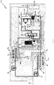
- Fig. 1 shows a first embodiment of a vapour-compression system 10 in the form of an air conditioning system.
- the system 10 includes a fixed speed compressor 14 for compressing refrigerant.
- the compressor 14 has a compressor inlet 14a for the intake of refrigerant and a compressor outlet 14b for the discharge of compressed refrigerant.
- the compressor 14 is electrically actuatable to an on-state and an off-state by a main control board 16 of the system 10, which is powered by the mains 20 (e.g., 240V).
- mains 20 e.g., 240V
- the system 10 further includes two heat exchangers 22, 24.
- the heat exchanger 22 is located in an outside area and the heat exchanger 24 is located in an inside area.
- a line 26 in Fig. 1 demarcates the outside and inside areas.
- the system 10 further comprises a reversing valve 28 for reversing the direction of flow of refrigerant in the system 10 such that the system 10 either cools or heats the inside area.
- each heat exchanger 22, 24 acts as either a condenser for condensing refrigerant flowing therethrough or an evaporator for evaporating refrigerant flowing therethrough.
- the heat exchanger 22 will hereinafter be referred to as the condenser and the heat exchanger 24 will hereinafter be referred to as the evaporator.
- the condenser 22 has a condenser inlet 22a for the intake of refrigerant and a condenser outlet 22b for discharging condensed and cooled refrigerant.
- the evaporator 24 has an evaporator inlet 24a for the intake of refrigerant and an evaporator outlet 24b for discharging evaporated and heated refrigerant.
- the condenser outlet 22b is fluidly connected to the evaporator inlet 24a.
- the reversing valve 28 is fluidly connected to the evaporator outlet 24b such that the evaporated refrigerant discharged therefrom is directed to the compressor inlet 14a.
- the reversing valve 28 is also fluidly connected to the condenser inlet 22a such that any refrigerant received via a reversing inlet 28a is directed to the condenser inlet 22a.
- the system 10 further includes two expansion valves 30, 32 located in the connection between the condenser outlet 22b and the evaporator inlet 24a.
- Each expansion valve 30, 32 is configured to abruptly reduce the pressure of refrigerant passing therethrough.
- the expansion valve 30 is used only when the system 10 is cooling the inner area and is bypassed when the system 10 is heating the inner area.
- the expansion valve 32 is used only when the system 10 is heating the inner area and is bypassed when the system 10 is cooling the inner area.
- the system 10 further includes two fans 34, 36.
- the fan 34 is configured to induce airflow across the condenser 22 and the fan 36 is configured to induce airflow across the evaporator 24.
- the system 10 further includes a flow-directing assembly 38 for directing refrigerant.
- the flow-directing assembly 38 comprises three flow ports 38a, 38b, 38c. Each of the flow ports 38a, 38b, 38c is configured for passage of refrigerant.
- the flow port 38a is fluidly connected to the flow ports 38b, 38c and the compressor outlet 14b.
- the flow port 38b is also fluidly connected to the flow port 38c and the reversing inlet 28a.
- the flow-directing assembly 38 further comprises three flow valves 40a, 40b, 40c.
- the flow valve 40a is located in the connection between the flow ports 38a, 38b.
- the flow valve 40a is electrically actuatable between an open position and a closed position for respectively allowing and preventing flow of refrigerant between the flow ports 38a, 38b.
- the flow valve 40b is located in the connection between the flow ports 38a, 38c.
- the flow valve 40b is electrically actuatable between an open and a closed position for respectively allowing and preventing flow of refrigerant between the flow ports 38a, 38c.
- the flow valve 40c is located in the connection between the flow ports 38b, 38c.
- the flow valve 40c is electrically actuatable between an open and a closed position for respectively allowing and preventing flow of refrigerant between the flow ports 38b, 38c.
- flow valves 40a, 40b, 40c may be pneumatically actuatable between their respective open and closed positions. In other embodiments, it will be appreciated that the flow valves 40a, 40b, 40c may be replaced by other valve combinations to achieve similar flow paths.
- the flow-directing assembly 38 further comprises two compressor sensors 42, 44.
- the compressor sensor 42 is located at or near the flow port 38a and is configured to measure the temperature and pressure of refrigerant at the flow port 38a.
- the compressor sensor 44 is located at or near the flow port 38b and is configured to measure the temperature and pressure of refrigerant at the flow port 38b.
- the system 10 further includes a storage assembly 46 for storing and releasing refrigerant.
- the storage assembly 46 comprises two storage ports 46a, 46b. Each of the storage ports 46a, 46b is configured for passage of refrigerant.
- the storage port 46a is fluidly connected to the flow port 38c and the storage port 46b is fluidly connected to the compressor inlet 14a.
- the storage assembly 46 further comprises a vacuum insulated container 48 for containment of compressed refrigerant.
- the container 48 has a container port 48a for passage of refrigerant and is fluidly connected to the storage ports 46a, 46b.
- the storage assembly 46 further comprises a storage condenser 50 for condensing refrigerant flowing therethrough.
- the storage condenser 50 is located in the connection between the container port 48a and the storage port 46b.
- the storage assembly 46 does not comprise the storage condenser 50. Instead, the container port 48a is directly connected to the storage port 46b.
- the storage assembly 46 further comprises two storage valves 52a, 52b.
- the storage valve 52a is located in the connection between the container port 48a and the storage port 52a.
- the storage valve 52a is electrically actuatable between an open position and a closed position for respectively allowing and preventing flow of refrigerant between the container port 48a and the storage port 52a.
- the storage valve 52a is in the form of a metered electronic valve such that the storage valve 52a is electrically adjustable in the open position to regulate the flow rate of refrigerant therethrough.
- the storage valve 52b is located in the connection between the container port 48a and the storage port 46b.
- the storage valve 52b is electrically actuatable between an open position and a closed position for respectively allowing and preventing flow of refrigerant between the container port 48a and the storage port 46b.
- the storage assembly 46 further comprises a container sensor 54 located at or near the container port 48a and configured to measure the temperature and pressure of refrigerant at the container port 48a.
- the system 10 further includes a suction valve 56 that fluidly connects the storage port 46b to the compressor inlet 14a.
- the suction valve 56 is electrically actuatable between an open position and a closed position for respectively allowing and preventing flow of refrigerant between the storage port 46b and the compressor inlet 14a.
- the suction valve 56 is in the form of a metered electronic valve such that the suction valve 56 is electrically adjustable in the open position to regulate the flow rate of refrigerant therethrough.
- system 10 does not comprise the suction valve 56. Instead, the storage port 46b is directly connected to the compressor inlet 14a.
- the system 10 further includes two condenser sensors 58a, 58b, two evaporator sensors 60a, 60b, and a suction sensor 62.
- the condenser sensors 58a, 58b are located at or near the condenser 22 and configured to measure the temperature and humidity of the air passed through the condenser 22.
- the evaporator sensors 60a, 60b are located near the evaporator 24 and configured to measure the temperature and humidity of the air passed through the evaporator 24.
- the suction sensor 62 is located at or near the suction valve 56 and configured to measure the temperature and pressure of the refrigerant at the compressor inlet 14a.
- controller 64 and the main control board 16 may be a single integrated component.
- the system 10 further includes a controller 64 in the form of an electronic control module.
- the controller 64 is electrically connected with the main control board 16, the flow-directing assembly 38, the storage assembly 46, the suction valve 56 and the sensors 58a, 58b, 60a, 60b, 62.
- the controller 64 is configured to actuate the valves 40a, 40b, 40c, 52a, 52b, 56 and also adjust the valves 52a, 56 in their open positions.
- the controller 64 has an antenna 66 to wirelessly communicate with a computer system to update its software and/or control parameters and/or usage details.
- the system 10 further includes two expansion sensors (not shown).
- a first of the expansion sensors is located near the expansion valve 30 and configured to measure the pressure and/or temperature of the refrigerant immediately after the expansion valve 30.
- a second of the expansion sensors is located near the expansion valve 32 and configured to measure the pressure and/or temperature of the refrigerant immediately after the expansion valve 32. It will be appreciated that, simile to the sensors 58a, 58b, 60a, 60b, 62, the controller 64 will be electrically connected to the expansion sensors.
- the main control board 16 actuates the compressor 14 to the on-state. Simultaneously, the controller 64 actuates the suction valve 56 to the closed position and configures the flow-directing assembly 38 into a compressor flow configuration by:
- the controller 64 based on one or more of the sensors 42, 44, 54, 58a, 58b, 60a, 60b, 62, the controller 64 is able to determine when the compressor 14 is generating more cooling capacity than required. In this event, the controller 64 configures the flow-directing assembly 38 into a storage flow configuration by:
- the controller 64 configures the flow-directing assembly 38 into the compressor configuration for normal operation of the system 10 as described above. Simultaneously, the controller 64 configures the storage assembly 46 into an isolation configuration by:
- the reduction in refrigerant within the system 10 causes the mechanical load from the compressor 14 to be reduced while in the on-state and thereby reduces unnecessary energy consumption.
- the controller 64 based on one or more of the sensors 42, 44, 54, 58a, 58b, 60a, 60b, 62, the controller 64 is able to determine when the system capacity is too low and not optimal for the current conditions. In this event, the controller 64 configures the storage assembly 46 into a releasing configuration by:
- the controller 64 determines that the optimal running capacity for the current load and conditions are met based on one or more of the sensors 42, 44, 54, 58a, 58b, 60a, 60b, 62, the controller 64 configures the configures the storage assembly 46 into the isolation configuration.
- the system 10 will cycle between the "storage during operation” and “releasing during operation” phases such that the compressor 14 is able to run at its most optimal state. Also, releasing the refrigerant stored in the container 48 through the storage condenser 50 may allow the compressor 14 to create a small amount of vacuum pressure without any extra mechanical load due to thinner refrigerant being introduced to the compressor inlet 14a. This slight vacuum effect may result in less mechanical load required for storing refrigerant in the container 48 in the "storage during operation” phase described above and the "shutdown” phase described below.
- the controller 64 During operation of the system 10, based on one or more of the sensors 42, 44, 54, 58a, 58b, 60a, 60b, 62, the controller 64 is able to determine when the predetermined temperature has been reached in the inside area or it is inefficient to continue running the compressor 14. In this event, the controller 64 sends a signal to the main control board 16 to maintain the compressor 14 in the on-state. Simultaneously, the controller 64 configures the flow-directing assembly 38 into the storage flow configuration and the storage assembly 46 into the storing configuration for storing compressed refrigerant in the container 48. It will again be appreciated that the compressed refrigerant stored in the container 48 will substantially maintain its thermal and pressure energy as the container 48 is vacuum insulated.
- the controller 64 sends a signal to the main control board 16 to actuate the compressor 14 to the off-state, configures the storage assembly 46 into the isolation configuration and configures the flow-directing assembly 38 into a no-flow configuration by:
- the controller 64 actuates the flow valve 40a to the open position in order relieve pressure from the compressor head. Once the sensor 42 indicates that the pressure has been relieved, the controller 64 actuates the flow valve 40a to the closed position.
- the controller 64 configures the flow-directing assembly 38 into a storage-compressor flow configuration by:
- the controller 64 determines enough stored energy is released into the system 10 based on one or more of the sensors 42, 44, 54, 58a, 58b, 60a, 60b, 62, the controller 64 sends a signal to the main control board 16 to actuate the compressor 14 to the on-state, configures the flow-directing assembly 38 into the condenser flow configuration, configures the storage assembly 46 to the releasing configuration and actuates the suction valve 56 to the open position. This allows refrigerant stored in the container 48 to be released into the compressor inlet 14a.
- the controller 64 determines that the container 48 has released enough stored energy based on one or more of the sensors 42, 44, 54, 58a, 58b, 60a, 60b, 62, the controller 64 configures the storage assembly 46 into the isolation configuration and actuates the suction valve 56 to the closed position.
- the system 10 arrives at optimal temperature and pressure faster due to the introduction of the stored thermal and pressure energy, and thereby reduces the running time required by the compressor 14 to achieve the required cooling capacity.
- the storage and release of otherwise wasted thermal and pressure energy developed by the compressor 14 during shutdown/startup phase cycles therefore saves energy.
- the startup" phase allows the compressor 14 to actuate to the on-state with less energy usage through decreasing the gas in the circuit and/or pressurising the suction side of the compressor 14 with the released refrigerant.
- An advantage of the system 10 is that cooling capacity of the system 10 can be reduced whilst it is operating, reducing energy usage, and still being able to shut down when this is the most efficient option.
- the system 10 described above can be provided as a new installation.
- installing the subsystem i.e., at least the flow-directing assembly 38, the storage assembly 46, and the controller 64
- an existing vapour-compression system by way of a retrofit can form an equivalent system.
- Such a retrofitted vapour-compression system will provide similar advantages as described above.
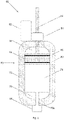
- Fig. 2 shows a storage assembly 68 of a second embodiment of a vapour-compression system (not shown).
- the second embodiment of the vapour-compression system is substantially similar to the first embodiment of the vapour-compression system 10 as described above. Accordingly, reference numerals used to denote components of the first embodiment of the vapour-compression system 10 will also be used to denote like components of the second embodiment of the vapour-compression system.
- the storage assembly 68 comprises a container 70.
- the container 70 is substantially cylindrical in shape and is vacuum insulated by a wall 72 to maintain the temperature and pressure of any refrigerant stored therein (typically, the refrigerant stored therein would be in the form of a super-heated gas).
- the storage assembly 68 further comprises a piston 74 located within the container 70 such that the wall 72, the piston 74 and an end 76 of the container 70 define an internal chamber 78. It will be appreciated that the refrigerant stored in the container 70 will be contained in the internal chamber 78.
- the piston 74 is dimensioned to allow for movement to and from the end 76 of the container 70, and is sealingly engaged with the wall 72 by seals 80. It will be appreciated that such movement would adjust the volume of the internal chamber 78.
- the container 70 comprises a container port 70a located at the end 76 to allow for passage of refrigerant to and from the internal chamber 78.
- the storage assembly 68 further comprises a low voltage (e.g., 6V-24V DC) high torque electric motor 82, a motor gear set 84 and a threaded connecting rod 86.
- a low voltage (e.g., 6V-24V DC) high torque electric motor 82 As shown in Fig. 2 , the connecting rod 86 is secured to the piston 74 and extends outwardly through an end 89 of the container 70.
- the motor gear set 84 is operatively engaged with the threading of the connecting rod 86 and the motor 82. Due to this arrangement, it will be appreciated that the piston 74 will be moved to or from the end 76 of the container 70 when the motor 82 is powered.
- the controller 64 is electrically connected to the motor 82 and controls its operation. It will also be appreciated that, in use, the motor 82 consumes substantially less energy than that of the compressor 14
- the storage assembly 68 further comprises a manifold 88 which is fluidly connected to the container port 70a, the flow port 38c and the compressor inlet 14a.
- the manifold 88 comprises one or more variable metering valves (not shown) that regulate refrigerant entering the container port 70a from the flow port 38c or leaving the container port 70a to the compressor inlet 14a.
- the manifold 88 is controlled by the controller 64 in a similar manner as described above in relation to storage valves 52a, 52b.
- the valve(s) of the manifold 88 allow refrigerant to flow via the container port 70a into the internal chamber 78 for containment.
- the piston 74 is moved by the motor 82 to vary the volume of the internal chamber 78.
- the piston 74 is moved away from the end 76 of the container 70 to increase the volume of the internal chamber 78 and thereby form a low pressure therein. This causes a suction effect in which refrigerant is drawn into the internal chamber 78. Accordingly, it will be appreciated that the compressor 14 will have a reduced load while refrigerant is being stored in the container 70 due to the suction effect and thus energy will be saved as the motor 82 requires substantially less power to operate than that of the compressor 14.
- the valve(s) of the manifold 88 seals the internal chamber 78 of the container 70 and the volume of the internal chamber 78 is varied to increase the pressure of refrigerant therein.
- the piston 74 is slowly moved towards the end 76 of the container 70 by the motor 82 to decrease the volume of the internal chamber 78 and thereby apply pressure to the refrigerant stored therein. Once a predetermined pressure is reached in the internal chamber 78 (i.e., a pressure higher than the rest of the system), the piston 74 is stopped.
- the valve(s) of the manifold 88 allow refrigerant to flow out of the internal chamber 78 towards the compressor inlet 14a and/or the condenser inlet 22a. It will be appreciated that the difference in pressure (i.e., high in the internal chamber 78 and low in the rest of the system) allows the refrigerant to readily flow out of the internal chamber 78.
- the valve(s) of the manifold 88 seals the internal chamber 78 of the container 70.
- An advantage of the storage assembly 68 is that refrigerant can readily flow from and to the compressor 14 when required as the variable volume of the internal chamber 78 can produce differences in pressure.
- Another advantage of the storage assembly 68 is that the peak loads experienced by the compressor 14 at startup may be reduced. For example, only a predetermined amount of stored refrigerant can be released to the compressor inlet 14a so that the compressor 14 can start with minimal head pressure as well as reduced load pressure. Then, the remaining refrigerant stored in the internal chamber 78 can be pressurised as described above to a predetermined pressure and another predetermined amount of refrigerant can be released. This process can be repeated until the system reaches full capacity.
- Another advantage of the storage assembly 68 is that the system is able to startup at a desired/optimal capacity rather than starting immediately at full capacity.
- Another advantage of the storage assembly 68 is that the volume of the internal chamber 78 can be adjusted to suit the capacity of each system. Accordingly, there is a reduced need to manufacture multiple sizes of the storage assembly 68 to suit different systems.
- the ability to vary the volume of the container 70 allows a reduction or increase in the capacity of the system by increasing or decreasing the amount of refrigerant in the system at any one time, whilst the system is in operation. This is due to the ability to create work to increase the pressure of the gas in the container 70, which is already in a stored super-heated state, to a pressure above that of the operating system. This allows for a high pressure to low pressure delivery system of the potential energy into the discharge of the system.
- increasing the internal size of the container 70 allows the creation of a low pressure suction (vacuum like state) when removing the super-heated refrigerant for storage.
- suction vacuum like state
- the operating pressures are reduced and therefore mechanical load on the system's compressor is reduced. This reduces electrical load and saves energy when the system, due to environmental conditions, does not require full capacity.
- the environmental conditions dictate that full or a higher capacity is required, the stored energy is reintroduced to the system. In this situation, the system compressor is not required to create the work to increase the capacity, only to maintain the reintroduced super-heated refrigerant (which is already at increased pressure and temperature).
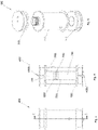
- Figs. 3 to 6 shows a third embodiment of a vapour-compression system 100 in the form of an air conditioning system not belonging to the invention.
- the system 100 includes a fixed speed compressor 140 for compressing refrigerant.
- the compressor 140 has a compressor inlet 140a for the intake of refrigerant and a compressor outlet 140b for the discharge of compressed refrigerant.
- the compressor 140 is electrically actuatable to an on-state and an off-state by a control system 160 of the system 100, which is powered by the mains (e.g., 240V).
- the system 100 further includes two heat exchangers 220, 240.
- the heat exchanger 220 is located in an outside area and the heat exchanger 240 is located in an inside area.
- the heat exchanger 220 is in the form of a condenser and the heat exchanger 240 is in the form of an evaporator.
- the condenser 220 has a condenser inlet 220a for the intake of refrigerant and a condenser outlet 220b for discharging condensed and cooled refrigerant.
- the evaporator 240 has an evaporator inlet 240a for the intake of refrigerant and an evaporator outlet 240b for discharging evaporated and heated refrigerant.
- the condenser outlet 220b is fluidly connected to the evaporator inlet 240a and the evaporator outlet 240b is fluidly connected to the compressor inlet 140a.
- the system 100 further includes an expansion valve 300 located in the connection between the condenser outlet 220b and the evaporator inlet 240a.
- the expansion valve 300 is configured to abruptly reduce the pressure of refrigerant passing therethrough.
- the system 100 further includes two fans 340, 360.
- the fan 340 is configured to induce airflow across the condenser 220 and the fan 360 is configured to induce airflow across the evaporator 240.
- the system 100 further includes a flow-directing assembly 380 for directing refrigerant.
- the flow-directing assembly 380 comprises three flow ports 380a, 380b, 380c. Each of the flow ports 380a, 380b, 380c is configured for passage of refrigerant.
- the flow port 380a is fluidly connected to the flow ports 380b, 380c and the compressor outlet 140b.
- the flow port 380b is also fluidly connected to the flow port 380c and the condenser inlet 220a.
- the flow-directing assembly 380 further comprises a passive valve 400a and a flow valve 400b.
- the passive valve 400a is located immediately following the flow port 380a, and prevents the backflow of refrigerant to the compressor 140.
- the flow valve 400b is located immediately following the passive valve 400a, and is a three-way electrically actuated ball valve.
- the flow valve 400b is actuatable to a first open flow position, a second open flow position, a third open flow position, and a closed position.
- the flow valve 400b in the first flow position allows the flow of refrigerant between the flow ports 380a, 380c.
- the flow valve 400b in the second flow position allows the flow of refrigerant between the flow ports 380a, 380b.
- the flow valve 400b in the third flow position allows the flow of refrigerant between the flow ports 380b, 380c. It will be appreciated that a similar flow configuration could be achieved through two twoway actuated ball valves, or through the use of three one-way actuated solenoid valves. It will be further appreciated that actuation may be achieved through other means such as pneumatic.
- the flow-directing assembly 380 further comprises three compressor sensors 420, 440, 540.
- the compressor sensor 420 is located at or near the flow port 380a and is configured to measure the temperature and pressure of refrigerant at the flow port 380a.
- the compressor sensor 440 is located at or near the flow port 380b and is configured to measure the temperature and pressure of refrigerant at the flow port 380b.
- the compressor sensor 540 is located at or near the flow port 380c and is configured to measure the temperature and pressure of refrigerant at the flow port 380c.
- the system 100 further includes a storage assembly 460 for storing and releasing refrigerant.
- the storage assembly 460 comprises a storage port 460a configured for passage of refrigerant.
- the storage port 460a is fluidly connected to the flow port 380c.
- the storage assembly 460 further comprises a vacuum insulated container 480 for containment of compressed refrigerant.
- the container 480 is substantially cylindrical in shape and is vacuum insulated by a wall 720 to maintain the temperature and pressure of any refrigerant stored therein (typically, the refrigerant stored therein would be in the form of a super-heated gas).
- the storage assembly 460 further comprises a piston 740 located within the container 480 such that the wall 720, the piston 740 and an end 760 of the container 480 define an internal chamber 780. Also, the wall 720, the piston 740 and an end 765 of the container 480 define an internal hydraulic chamber 785.
- the ends 760, 765 are in the form of end plates. It will be appreciated that the refrigerant stored in the container 480 will be contained in the internal chamber 780.
- the piston 740 is dimensioned to allow for movement to and from the end 760 of the container 480, and is sealingly engaged with the wall 720 by a seal 800. It will be appreciated that such movement would adjust the volume of the internal chamber 780.
- the container 480 comprises a container port 480a located at the end 760 to allow for passage of refrigerant to and from the internal chamber 780.
- the container port 480a is fluidly connected to the storage port 460a.
- the container 480 further comprises a hydraulic fluid container port 480b in the end 765 for passage of hydraulic fluid to and from the internal hydraulic chamber 785.
- the storage assembly 460 further comprises a hydraulic fluid tank H2 and a hydraulic pump H1 that are fluidly connected to the hydraulic fluid container port 480b. It will be appreciated that the piston 740 will be moved to and from the end 760 of the container 480 with the introduction and release of hydraulic fluid into the internal chamber 785.
- the storage assembly 460 comprises two hydraulic valves 520b, 520c. The hydraulic valve 520b is located in the connection between the container port 480b and the hydraulic pump H1.
- the hydraulic valve 520b is electrically actuatable between an open position and a closed position for respectively allowing and preventing flow of hydraulic fluid between the container port 480b and the hydraulic pump H1.
- the hydraulic valve 520c is located in the connection between the control port 480b and the hydraulic fluid tank H2.
- the hydraulic valve 520c is electrically actuatable between an open and closed position for respectively allowing and preventing flow of hydraulic fluid between the container port 480b and the hydraulic fluid tank H2.
- the operation of the storage assembly 460 will be substantially similar to that of the storage assembly 68 of the second embodiment of the vapour-compression system. However, the storage assembly 460 will utilise hydraulic fluid to move the piston 740 as opposed to a motor mechanically connected to the piston 740.
- the storage assembly 460 further comprises a storage valve 520a.
- the storage valve 520a is located in the connection between the container port 480a and the storage port 460a.
- the storage valve 520a is electrically actuatable between an open position and a closed position for respectively allowing and preventing flow of refrigerant between the storage port 460a and the container port 480a.
- the storage assembly 460 further comprises four sensors 540a, 540b, 540c, 540d.
- a first container sensor 540a is located at or near the internal chamber 780 and configured to measure the temperature and pressure of refrigerant stored within the container 480.
- a second container sensor 540b is located at or near the internal chamber 785 and configured to measure the temperature and pressure of hydraulic fluid stored within the container 480.
- a third container sensor 540c is located at or near the vacuum annulus of the container 480 and configured to measure the pressure within the vacuum annulus.
- a tank sensor 540d is located at or near the hydraulic fluid tank H2 and configured to measure the pressure of the hydraulic fluid within the hydraulic fluid tank H2. It will be appreciated that the tank sensor 540d can be used to determine the position of the piston 740 within the container 480.
- the system 100 further includes a suction valve 560 that fluidly connects the storage port 460a to the compressor inlet 140a.
- the suction valve 560 is electrically actuatable between an open position and a closed position for respectively allowing and preventing flow of refrigerant between the storage port 460a and the compressor inlet 140a. Further, the suction valve 560 allows system 100 to be pressure equalized.
- the system 100 further includes two condenser sensors 580a, 580b, two evaporator sensors 600a, 600b, and a suction sensor 620.
- the condenser sensors 580a, 580b are located at or near the condenser 220 and configured to measure the temperature and humidity of the air passed through the condenser 220.
- the evaporator sensors 600a, 600b are located near the evaporator 240 and configured to measure the temperature and humidity of the air passed through the evaporator 240.
- the suction sensor 620 is located at or near the compressor inlet 140a and configured to measure the temperature and pressure of the refrigerant at the compressor inlet 140a.
- the system 100 also includes two more pressure/temperature sensors ES1, ES2. These sensors ES1, ES2 are respectively configured to measure the temperature and pressure of the refrigerant at the inlet and outlet of the expansion valve 300.
- the control system 160 is electrically connected to the flow-directing assembly 380, the storage assembly 460, the suction valve 560 and the sensors 580a, 580b, 600a, 600b, 620, ES1, ES2.
- the control system 160 is configured to actuate the valves 400a, 400b, 520a, 520b, 520c, 560.
- the control system 160 has an antenna 660 to wirelessly communicate with a computer system to update its software and/or control parameters and usage details.
- the compressor 140 As the system 100 is running, the compressor 140 is in the on-state. Also, the control system 160 has: actuated the suction valve 560 to the closed position; and configured the flow-directing assembly 380 into a compressor-condenser flow configuration by actuating the flow valve 400b to the second flow position.
- the flow-directing assembly 380 in the compressor-condenser flow configuration directs compressed refrigerant from the compressor outlet 140b to the condenser inlet 220a for normal operation of the system 100 (i.e., the vapour-compression cycle).
- the control system 160 based on one or more of the sensors 420, 440, 540, 540a, 540b, 540c, 540d, 580a, 580b, 600a, 600b, 620, ES1, ES2, the control system 160 is able to determine when the compressor 140 is generating more cooling capacity than required. In this event, the control system 160 configures the flow-directing assembly 380 into a storage flow configuration by actuating 400b to the first flow position. Simultaneously, the control system 160 configures the storage container 480 into a storage configuration by actuating the storage valve 520a to the open position. In addition, the control system 160 actuates the hydraulic valves 520b and 520c to the open positions.
- control system 160 determines that the optimal running capacity for the current load and conditions are met based on one or more of the sensors 420, 440, 540, 540a, 540b, 540c, 540d, 580a, 580b, 600a, 600b, 620, ES1, ES2, the control system 160 configures the flow-directing assembly 380 into the compressor-condenser configuration for normal operation of the system 100 as described above. Simultaneously, the control system 160 configures the storage assembly 460 into an isolation configuration by actuating the storage valve 520a to the closed position. In addition, the control system 160 actuates hydraulic valve 520b to the closed position.
- the storage assembly 460 in the isolation configuration seals compressed refrigerant in the container 480. It will be appreciated that the compressed refrigerant stored in the container 480 will substantially maintain its thermal and pressure energy as the container 480 is vacuum insulated and the storage valve 520a and the hydraulic valve 520b are closed. It will also be appreciated that this 'storage during operation' can be performed multiple times in succession to continue to lower the cooling capacity of the system 100 (through a reduction in the system refrigerant) as required.
- control system 160 During operation of the system 100, based on one or more of the sensors 420, 440, 540, 540a, 540b, 540c, 540d, 580a, 580b, 600a, 600b, 620, ES1, ES2, the control system 160 is able to determine when the capacity of the system 100 is too low and/or not optimal for the current conditions. In this event, the control system 160 actuates the hydraulic pump H1 to the on-state and the hydraulic valve 520b to the open position.
- the refrigerant in the internal chamber 780 of the container 480 is compressed until, based on one or more of the sensors 420, 440, 540, 540a, 540b, 540c, 540d, 580a, 580b, 600a, 600b, 620, ES1, ES2, the control system 160 determines that the stored refrigerant is at a higher pressure than the pressure at the compressor inlet 140a. Then, the control system 160 configures the storage assembly 460 into a releasing configuration by actuating the storage valve 520a to the open position. Simultaneously, the control system 160 actuates the suction valve 560 to the open position. In this releasing configuration of the storage assembly 460, the higher pressure refrigerant is released into the compressor inlet 140a. During this process, the hydraulic pump H1 maintains the pressure of the container 480 above the pressure of the compressor inlet 140a.
- control system 160 determines that the optimal running capacity for the current load and conditions are met based on one or more of the sensors 420, 440, 540, 540a, 540b, 540c, 540d, 580a, 580b, 600a, 600b, 620, ES1, ES2, the control system 100 configures the storage assembly 460 into the isolation configuration.
- system 100 will cycle between the "storage during operation” and “releasing during operation” phases such that the compressor 140 is able to run at its most optimal state.
- the control system 160 based on one or more of the sensors 420, 440, 540, 540a, 540b, 540c, 540d, 580a, 580b, 600a, 600b, 620, ES1, ES2, the control system 160 is able to determine when the predetermined temperature has been reached in the inside area, or it is inefficient to continue running. In this event, the control system 160 configures: the flow-directing assembly 380 into the storage flow configuration; and the storage assembly 460 into the storing configuration. It will be appreciated that the compressed refrigerant stored in the container 480 will substantially maintain its thermal and pressure energy as the container 480 is vacuum insulated and the valves 520a, 520b remains closed once filled. It will be appreciated that the capturing of the gas through lowering the pressure of the container 480 below the compressor outlet 140b pressure will reduce the compressor energy usage during the storing phase.
- the control system 160 actuates the compressor 140 to the off-state, configures the storage assembly 460 into the isolation configuration and configures the flow-directing assembly 380 into a no-flow configuration by actuating the flow valve 400b to the closed position.
- the control system 160 actuates the suction valve 560 to the open position and the flow-directing assembly 380 to the storage configuration in order to relieve pressure from the compressor head. Once the sensor 420 indicates that the pressure has been relieved, the control system 160 actuates the suction valve 560 to the closed position and the flow-directing assembly 380 to the no-flow configuration.
- the control system 160 configures the flow-directing assembly 380 into a storage-compressor flow configuration by actuating the flow valve 400b to the third flow position. Simultaneously, the control system 160 actuates the hydraulic pump H1 to the on-state, the control valve 520b to the open position, and the hydraulic valve 520c to the closed position.
- the flow-directing assembly 380 in the storage-compressor flow configuration allows refrigerant to flow from the flow port 380c to the condenser inlet 220a via the flow port 380b.
- control system 160 configures the storage assembly 460 into a pressure-balancing configuration by actuating the storage valve 520a to the open position. Simultaneously, the control system 160 actuates the suction valve 560 to the closed position.
- the storage assembly 460 in the pressure-balancing configuration releases compressed refrigerant stored in the container 480 to flow through the storage port 460a, the flow port 380c, and the flow port 380b to the condenser inlet 220a.
- control system 160 determines based on one or more of the sensors 420, 440, 540, 540a, 540b, 540c, 540d, 580a, 580b, 600a, 600b, 620, ES1, ES2 that the system 100 is ready to restart, the control system 160 actuates the compressor 140 to the on-state. During the pressure-balancing process the control system 160 actuates the hydraulic pump H1, the hydraulic valve 520b and the hydraulic valve 520c to maintain the stored refrigerant pressure above the compressor outlet 140a pressure.
- the control system 160 may also choose based on one or more of the sensors 420, 440, 540, 540a, 540b, 540c, 540d, 580a, 580b, 600a, 600b, 620, ES1, ES2 to configure the flow directing assembly 380 to the compressor-condenser flow configuration, and actuate the suction valve 560 to the open position to release the stored refrigerant into the compressor inlet 140a.
- control system 160 configures the storage assembly 460 into the isolation configuration and actuates the suction valve 560 to the closed position and the flow directing valve 400b to the compressor -condenser configuration.
- the expansion valve 300 has an orifice with an adjustable size.
- the system 100 further includes an orifice sensor which is located in the expansion valve 300 and configured to measure the size of the orifice.
- the control system 160 is electrically connected to the orifice of the expansion valve 300 and able to adjust the size of the orifice of the expansion valve 300 based on the orifice sensor and/or one or more of the sensors 420, 440, 540, 540a, 540b, 540c, 540d, 580a, 580b, 600a, 600b, 620, ES1, ES2 during operation of the system 100.
- the adjustment in the size of the orifice of the expansion valve 300 will adjust the expansion of the refrigerant passing therethrough and may facilitate refrigerant flow during any of the above phases of the operation (e.g., the "startup” phase, the "storage during operation” phase etc).
- the system 100 arrives at optimal temperature and pressure faster due to the introduction of the stored thermal and pressure energy and thereby reduces the running time required by the compressor 140 to achieve the required cooling capacity.
- the storage and release of otherwise wasted thermal and pressure energy developed by the compressor 140 during shutdown/startup phase cycles therefore saves energy.
- optimization of the start procedure allows the compressor to actuate to the on state with less energy usage through decreasing the gas in the circuit, pressurizing the suction side of the compressor 140 with the released refrigerant, or initiating the flow of refrigerant in the circuit at startup.
- An advantage of the system 100 is that cooling capacity of the system 100 can be actively modified whilst it is operating, optimizing energy usage based on the required capacity, whilst still able to shut down when this is the most efficient option.
- the system 100 described above can be provided as a new installation.
- installing the subsystem i.e., at least the flow-directing assembly 380, the storage assembly 460, and control system 160
- installing the subsystem i.e., at least the flow-directing assembly 380, the storage assembly 460, and control system 160
- an existing vapour-compression system by way of a retrofit can form an equivalent system.
- Such a retrofitted vapour-compression system will provide similar advantages as described above.
- the vapour-compression systems 10, 100 may be in the form of a refrigeration system.
- the compressors 14, 140 may be variable speed compressors.
- the flow-directing assembly 38, 380 may be fluidly connected at other locations of a vapour-compression circuit (e.g., between the condenser and the evaporator, or between the evaporator and the compressor) and perform a similar operation as described above.
Landscapes
- Engineering & Computer Science (AREA)
- Physics & Mathematics (AREA)
- Mechanical Engineering (AREA)
- Thermal Sciences (AREA)
- General Engineering & Computer Science (AREA)
- Compressor (AREA)
- Devices That Are Associated With Refrigeration Equipment (AREA)
- Applications Or Details Of Rotary Compressors (AREA)
- Vaporization, Distillation, Condensation, Sublimation, And Cold Traps (AREA)
- Compressors, Vaccum Pumps And Other Relevant Systems (AREA)
- Control Of Positive-Displacement Pumps (AREA)
- Air-Conditioning For Vehicles (AREA)
- Structures Of Non-Positive Displacement Pumps (AREA)
Applications Claiming Priority (3)
| Application Number | Priority Date | Filing Date | Title |
|---|---|---|---|
| AU2015902860A AU2015902860A0 (en) | 2015-07-20 | A subsystem for a vapour-compression system, a vapour-compression system, and a method for a vapour-compression system | |
| AU2016900063A AU2016900063A0 (en) | 2016-01-11 | A subsystem for a vapour-compression system, a vapour-compression system, and a method for a vapour-compression system | |
| PCT/AU2016/000255 WO2017011852A1 (en) | 2015-07-20 | 2016-07-18 | A subsystem for a vapour-compression system, a vapour-compression system, and a method for a vapour- compression system |
Publications (3)
| Publication Number | Publication Date |
|---|---|
| EP3325899A1 EP3325899A1 (en) | 2018-05-30 |
| EP3325899A4 EP3325899A4 (en) | 2019-03-27 |
| EP3325899B1 true EP3325899B1 (en) | 2022-07-06 |
Family
ID=57833478
Family Applications (1)
| Application Number | Title | Priority Date | Filing Date |
|---|---|---|---|
| EP16826913.2A Active EP3325899B1 (en) | 2015-07-20 | 2016-07-18 | A subsystem for a vapour-compression system |
Country Status (13)
| Country | Link |
|---|---|
| US (1) | US10401063B2 (pl) |
| EP (1) | EP3325899B1 (pl) |
| JP (1) | JP6925333B2 (pl) |
| KR (1) | KR102588794B1 (pl) |
| CN (2) | CN113834247B (pl) |
| AU (1) | AU2016297673B2 (pl) |
| BR (1) | BR112018000516B1 (pl) |
| CA (1) | CA2989952C (pl) |
| ES (1) | ES2927895T3 (pl) |
| MX (1) | MX2018000655A (pl) |
| NZ (1) | NZ738331A (pl) |
| PL (1) | PL3325899T3 (pl) |
| WO (1) | WO2017011852A1 (pl) |
Families Citing this family (2)
| Publication number | Priority date | Publication date | Assignee | Title |
|---|---|---|---|---|
| CN107560205B (zh) * | 2017-08-09 | 2021-06-15 | 重庆海尔制冷电器有限公司 | 一种冰箱的开机方法和装置 |
| CN108050737B (zh) * | 2017-12-13 | 2020-11-03 | 阳谷祥光铜业有限公司 | 一种循环水热能回收装置以及方法 |
Citations (1)
| Publication number | Priority date | Publication date | Assignee | Title |
|---|---|---|---|---|
| EP2818808A1 (en) * | 2012-02-23 | 2014-12-31 | Toyota Jidosha Kabushiki Kaisha | Cooling device, vehicle provided with same, and control method for cooling device |
Family Cites Families (20)
| Publication number | Priority date | Publication date | Assignee | Title |
|---|---|---|---|---|
| JPS5960466U (ja) * | 1982-10-18 | 1984-04-20 | 株式会社東芝 | 冷凍サイクル |
| JPH05141816A (ja) * | 1991-11-25 | 1993-06-08 | Sharp Corp | 冷媒回収装置付冷凍機器 |
| NO915127D0 (no) * | 1991-12-27 | 1991-12-27 | Sinvent As | Kompresjonsanordning med variabelt volum |
| KR100386657B1 (ko) * | 2000-10-04 | 2003-06-02 | 엘지전자 주식회사 | 공기조화기 |
| JP2002156166A (ja) * | 2000-11-20 | 2002-05-31 | Fujitsu General Ltd | 多室形空気調和機 |
| KR20060039344A (ko) * | 2004-11-02 | 2006-05-08 | 주식회사 대우일렉트로닉스 | 멀티에어컨에서 압축기의 압력 평형장치 |
| US7216495B1 (en) * | 2006-03-02 | 2007-05-15 | Harrison Thomas D | Air conditioning system |
| KR20070097992A (ko) * | 2006-03-30 | 2007-10-05 | 엘지전자 주식회사 | 공기 조화기 및 그 제어방법 |
| CN100453928C (zh) * | 2007-10-09 | 2009-01-21 | 上海理工大学 | 自动复叠制冷系统排气压力的调节装置 |
| KR101622225B1 (ko) * | 2010-01-13 | 2016-05-18 | 엘지전자 주식회사 | 공기조화장치 |
| US8678786B2 (en) * | 2010-10-21 | 2014-03-25 | Honeywell International Inc. | Scroll compressor with partial unloader for start-up |
| JP5798402B2 (ja) * | 2011-08-01 | 2015-10-21 | トヨタ自動車株式会社 | 冷却装置 |
| JP5868224B2 (ja) * | 2012-03-07 | 2016-02-24 | 住友重機械工業株式会社 | クライオポンプシステム、クライオポンプシステムの運転方法、及び圧縮機ユニット |
| JP6179842B2 (ja) * | 2012-09-28 | 2017-08-16 | パナソニックIpマネジメント株式会社 | 冷凍装置及び冷凍装置用増設冷媒量調整装置 |
| DE102012218700A1 (de) * | 2012-10-15 | 2014-04-17 | BSH Bosch und Siemens Hausgeräte GmbH | Kältegerät |
| CN203231423U (zh) * | 2013-04-15 | 2013-10-09 | 广东美的制冷设备有限公司 | 自动调节系统冷媒量的空调器 |
| CN103604245B (zh) * | 2013-07-22 | 2016-04-13 | 陈恩鉴 | 一种装有能效增大器的蒸气压缩式空调系统 |
| CN104344508B (zh) * | 2013-07-26 | 2017-06-30 | 广东美的制冷设备有限公司 | 调节冷媒充填量和冷媒循环量的空调系统及方法 |
| US9297565B2 (en) * | 2013-08-26 | 2016-03-29 | Lennox Industries Inc. | Charge management for air conditioning |
| DE102014003908B4 (de) * | 2014-03-19 | 2015-10-15 | Audi Ag | Fahrzeugklimaanlage mit einem Kältemittelkreislauf |
-
2016
- 2016-07-18 EP EP16826913.2A patent/EP3325899B1/en active Active
- 2016-07-18 KR KR1020187002275A patent/KR102588794B1/ko active Active
- 2016-07-18 WO PCT/AU2016/000255 patent/WO2017011852A1/en not_active Ceased
- 2016-07-18 PL PL16826913.2T patent/PL3325899T3/pl unknown
- 2016-07-18 JP JP2018522823A patent/JP6925333B2/ja active Active
- 2016-07-18 ES ES16826913T patent/ES2927895T3/es active Active
- 2016-07-18 BR BR112018000516-9A patent/BR112018000516B1/pt active IP Right Grant
- 2016-07-18 NZ NZ738331A patent/NZ738331A/en unknown
- 2016-07-18 CN CN202111179395.2A patent/CN113834247B/zh active Active
- 2016-07-18 MX MX2018000655A patent/MX2018000655A/es unknown
- 2016-07-18 CN CN201680042788.XA patent/CN108027182B/zh active Active
- 2016-07-18 US US15/746,387 patent/US10401063B2/en active Active
- 2016-07-18 AU AU2016297673A patent/AU2016297673B2/en active Active
- 2016-07-18 CA CA2989952A patent/CA2989952C/en active Active
Patent Citations (1)
| Publication number | Priority date | Publication date | Assignee | Title |
|---|---|---|---|---|
| EP2818808A1 (en) * | 2012-02-23 | 2014-12-31 | Toyota Jidosha Kabushiki Kaisha | Cooling device, vehicle provided with same, and control method for cooling device |
Also Published As
| Publication number | Publication date |
|---|---|
| AU2016297673A1 (en) | 2018-01-18 |
| CN113834247B (zh) | 2023-09-01 |
| WO2017011852A9 (en) | 2017-03-30 |
| BR112018000516B1 (pt) | 2023-03-28 |
| JP6925333B2 (ja) | 2021-08-25 |
| KR102588794B1 (ko) | 2023-10-12 |
| ES2927895T3 (es) | 2022-11-11 |
| MX2018000655A (es) | 2018-09-06 |
| EP3325899A1 (en) | 2018-05-30 |
| AU2016297673B2 (en) | 2022-03-31 |
| CA2989952C (en) | 2023-10-03 |
| NZ738331A (en) | 2023-06-30 |
| CN113834247A (zh) | 2021-12-24 |
| CN108027182A (zh) | 2018-05-11 |
| US20180195779A1 (en) | 2018-07-12 |
| US10401063B2 (en) | 2019-09-03 |
| CA2989952A1 (en) | 2017-01-26 |
| EP3325899A4 (en) | 2019-03-27 |
| KR20180030988A (ko) | 2018-03-27 |
| JP2018521297A (ja) | 2018-08-02 |
| PL3325899T3 (pl) | 2022-11-28 |
| WO2017011852A1 (en) | 2017-01-26 |
| BR112018000516A2 (pt) | 2018-09-18 |
| CN108027182B (zh) | 2021-10-15 |
Similar Documents
| Publication | Publication Date | Title |
|---|---|---|
| EP3023714B1 (en) | A method for controlling a vapour compression system with an ejector | |
| CN102326035B (zh) | 热泵系统 | |
| EP2751499B1 (en) | Refrigeration system and refrigeration method providing heat recovery | |
| JP5475874B2 (ja) | ヒートポンプシステム | |
| CN102037293A (zh) | 具有可调节设定值的制冷机 | |
| CN108139086A (zh) | 空调及控制空调的方法 | |
| JP6057871B2 (ja) | ヒートポンプシステム、及び、ヒートポンプ式給湯器 | |
| CN105593610A (zh) | 热泵系统及热泵式供热水机 | |
| AU2020246687A1 (en) | Hot water supply apparatus | |
| EP3325899B1 (en) | A subsystem for a vapour-compression system | |
| KR101558503B1 (ko) | 멀티형 공기조화기 및 그 운전 방법 | |
| KR102229436B1 (ko) | 냉동 사이클 장치 | |
| KR101255766B1 (ko) | 공기열 히트펌프를 이용한 온수공급장치 | |
| CN206770176U (zh) | 压缩机和空气能热水器系统 | |
| CN109899918A (zh) | 用于住宅房间中空气更新的改进的热泵设备及其操作方法 | |
| EP1966549B1 (en) | A cooling device | |
| GB2516030A (en) | Heat Pump | |
| JP6029569B2 (ja) | ヒートポンプシステム、及び、ヒートポンプ式給湯器 | |
| JP2016090180A5 (pl) | ||
| BR112018071220B1 (pt) | Sistema de refrigeração e sistemas de condensador e evaporador do mesmo | |
| BR112018071218B1 (pt) | Sistema de evaporador e condensador com um sub-resfriador para sistemas de refrigeração |
Legal Events
| Date | Code | Title | Description |
|---|---|---|---|
| STAA | Information on the status of an ep patent application or granted ep patent |
Free format text: STATUS: THE INTERNATIONAL PUBLICATION HAS BEEN MADE |
|
| PUAI | Public reference made under article 153(3) epc to a published international application that has entered the european phase |
Free format text: ORIGINAL CODE: 0009012 |
|
| STAA | Information on the status of an ep patent application or granted ep patent |
Free format text: STATUS: REQUEST FOR EXAMINATION WAS MADE |
|
| 17P | Request for examination filed |
Effective date: 20171220 |
|
| AK | Designated contracting states |
Kind code of ref document: A1 Designated state(s): AL AT BE BG CH CY CZ DE DK EE ES FI FR GB GR HR HU IE IS IT LI LT LU LV MC MK MT NL NO PL PT RO RS SE SI SK SM TR |
|
| AX | Request for extension of the european patent |
Extension state: BA ME |
|
| DAV | Request for validation of the european patent (deleted) | ||
| DAX | Request for extension of the european patent (deleted) | ||
| A4 | Supplementary search report drawn up and despatched |
Effective date: 20190222 |
|
| RIC1 | Information provided on ipc code assigned before grant |
Ipc: F24F 3/00 20060101ALI20190218BHEP Ipc: F24F 1/00 20190101ALI20190218BHEP Ipc: F25B 41/00 20060101AFI20190218BHEP |
|
| STAA | Information on the status of an ep patent application or granted ep patent |
Free format text: STATUS: EXAMINATION IS IN PROGRESS |
|
| 17Q | First examination report despatched |
Effective date: 20200908 |
|
| GRAP | Despatch of communication of intention to grant a patent |
Free format text: ORIGINAL CODE: EPIDOSNIGR1 |
|
| STAA | Information on the status of an ep patent application or granted ep patent |
Free format text: STATUS: GRANT OF PATENT IS INTENDED |
|
| INTG | Intention to grant announced |
Effective date: 20220201 |
|
| GRAS | Grant fee paid |
Free format text: ORIGINAL CODE: EPIDOSNIGR3 |
|
| GRAA | (expected) grant |
Free format text: ORIGINAL CODE: 0009210 |
|
| STAA | Information on the status of an ep patent application or granted ep patent |
Free format text: STATUS: THE PATENT HAS BEEN GRANTED |
|
| AK | Designated contracting states |
Kind code of ref document: B1 Designated state(s): AL AT BE BG CH CY CZ DE DK EE ES FI FR GB GR HR HU IE IS IT LI LT LU LV MC MK MT NL NO PL PT RO RS SE SI SK SM TR |
|
| REG | Reference to a national code |
Ref country code: AT Ref legal event code: REF Ref document number: 1503115 Country of ref document: AT Kind code of ref document: T Effective date: 20220715 Ref country code: CH Ref legal event code: EP |
|
| REG | Reference to a national code |
Ref country code: DE Ref legal event code: R096 Ref document number: 602016073390 Country of ref document: DE |
|
| REG | Reference to a national code |
Ref country code: IE Ref legal event code: FG4D |
|
| REG | Reference to a national code |
Ref country code: NL Ref legal event code: FP |
|
| REG | Reference to a national code |
Ref country code: LT Ref legal event code: MG9D |
|
| REG | Reference to a national code |
Ref country code: ES Ref legal event code: FG2A Ref document number: 2927895 Country of ref document: ES Kind code of ref document: T3 Effective date: 20221111 |
|
| REG | Reference to a national code |
Ref country code: GR Ref legal event code: EP Ref document number: 20220401982 Country of ref document: GR Effective date: 20221109 |
|
| PG25 | Lapsed in a contracting state [announced via postgrant information from national office to epo] |
Ref country code: SE Free format text: LAPSE BECAUSE OF FAILURE TO SUBMIT A TRANSLATION OF THE DESCRIPTION OR TO PAY THE FEE WITHIN THE PRESCRIBED TIME-LIMIT Effective date: 20220706 Ref country code: RS Free format text: LAPSE BECAUSE OF FAILURE TO SUBMIT A TRANSLATION OF THE DESCRIPTION OR TO PAY THE FEE WITHIN THE PRESCRIBED TIME-LIMIT Effective date: 20220706 Ref country code: PT Free format text: LAPSE BECAUSE OF FAILURE TO SUBMIT A TRANSLATION OF THE DESCRIPTION OR TO PAY THE FEE WITHIN THE PRESCRIBED TIME-LIMIT Effective date: 20221107 Ref country code: NO Free format text: LAPSE BECAUSE OF FAILURE TO SUBMIT A TRANSLATION OF THE DESCRIPTION OR TO PAY THE FEE WITHIN THE PRESCRIBED TIME-LIMIT Effective date: 20221006 Ref country code: LV Free format text: LAPSE BECAUSE OF FAILURE TO SUBMIT A TRANSLATION OF THE DESCRIPTION OR TO PAY THE FEE WITHIN THE PRESCRIBED TIME-LIMIT Effective date: 20220706 Ref country code: LT Free format text: LAPSE BECAUSE OF FAILURE TO SUBMIT A TRANSLATION OF THE DESCRIPTION OR TO PAY THE FEE WITHIN THE PRESCRIBED TIME-LIMIT Effective date: 20220706 Ref country code: FI Free format text: LAPSE BECAUSE OF FAILURE TO SUBMIT A TRANSLATION OF THE DESCRIPTION OR TO PAY THE FEE WITHIN THE PRESCRIBED TIME-LIMIT Effective date: 20220706 |
|
| REG | Reference to a national code |
Ref country code: AT Ref legal event code: MK05 Ref document number: 1503115 Country of ref document: AT Kind code of ref document: T Effective date: 20220706 |
|
| PG25 | Lapsed in a contracting state [announced via postgrant information from national office to epo] |
Ref country code: IS Free format text: LAPSE BECAUSE OF FAILURE TO SUBMIT A TRANSLATION OF THE DESCRIPTION OR TO PAY THE FEE WITHIN THE PRESCRIBED TIME-LIMIT Effective date: 20221106 |
|
| REG | Reference to a national code |
Ref country code: CH Ref legal event code: PL |
|
| REG | Reference to a national code |
Ref country code: BE Ref legal event code: MM Effective date: 20220731 |
|
| REG | Reference to a national code |
Ref country code: DE Ref legal event code: R097 Ref document number: 602016073390 Country of ref document: DE |
|
| PG25 | Lapsed in a contracting state [announced via postgrant information from national office to epo] |
Ref country code: SM Free format text: LAPSE BECAUSE OF FAILURE TO SUBMIT A TRANSLATION OF THE DESCRIPTION OR TO PAY THE FEE WITHIN THE PRESCRIBED TIME-LIMIT Effective date: 20220706 Ref country code: RO Free format text: LAPSE BECAUSE OF FAILURE TO SUBMIT A TRANSLATION OF THE DESCRIPTION OR TO PAY THE FEE WITHIN THE PRESCRIBED TIME-LIMIT Effective date: 20220706 Ref country code: MC Free format text: LAPSE BECAUSE OF FAILURE TO SUBMIT A TRANSLATION OF THE DESCRIPTION OR TO PAY THE FEE WITHIN THE PRESCRIBED TIME-LIMIT Effective date: 20220706 Ref country code: LU Free format text: LAPSE BECAUSE OF NON-PAYMENT OF DUE FEES Effective date: 20220718 Ref country code: LI Free format text: LAPSE BECAUSE OF NON-PAYMENT OF DUE FEES Effective date: 20220731 Ref country code: DK Free format text: LAPSE BECAUSE OF FAILURE TO SUBMIT A TRANSLATION OF THE DESCRIPTION OR TO PAY THE FEE WITHIN THE PRESCRIBED TIME-LIMIT Effective date: 20220706 Ref country code: CZ Free format text: LAPSE BECAUSE OF FAILURE TO SUBMIT A TRANSLATION OF THE DESCRIPTION OR TO PAY THE FEE WITHIN THE PRESCRIBED TIME-LIMIT Effective date: 20220706 Ref country code: CH Free format text: LAPSE BECAUSE OF NON-PAYMENT OF DUE FEES Effective date: 20220731 Ref country code: AT Free format text: LAPSE BECAUSE OF FAILURE TO SUBMIT A TRANSLATION OF THE DESCRIPTION OR TO PAY THE FEE WITHIN THE PRESCRIBED TIME-LIMIT Effective date: 20220706 |
|
| PLBE | No opposition filed within time limit |
Free format text: ORIGINAL CODE: 0009261 |
|
| STAA | Information on the status of an ep patent application or granted ep patent |
Free format text: STATUS: NO OPPOSITION FILED WITHIN TIME LIMIT |
|
| PG25 | Lapsed in a contracting state [announced via postgrant information from national office to epo] |
Ref country code: SK Free format text: LAPSE BECAUSE OF FAILURE TO SUBMIT A TRANSLATION OF THE DESCRIPTION OR TO PAY THE FEE WITHIN THE PRESCRIBED TIME-LIMIT Effective date: 20220706 Ref country code: EE Free format text: LAPSE BECAUSE OF FAILURE TO SUBMIT A TRANSLATION OF THE DESCRIPTION OR TO PAY THE FEE WITHIN THE PRESCRIBED TIME-LIMIT Effective date: 20220706 Ref country code: BE Free format text: LAPSE BECAUSE OF NON-PAYMENT OF DUE FEES Effective date: 20220731 |
|
| 26N | No opposition filed |
Effective date: 20230411 |
|
| PG25 | Lapsed in a contracting state [announced via postgrant information from national office to epo] |
Ref country code: AL Free format text: LAPSE BECAUSE OF FAILURE TO SUBMIT A TRANSLATION OF THE DESCRIPTION OR TO PAY THE FEE WITHIN THE PRESCRIBED TIME-LIMIT Effective date: 20220706 |
|
| P01 | Opt-out of the competence of the unified patent court (upc) registered |
Effective date: 20230602 |
|
| PG25 | Lapsed in a contracting state [announced via postgrant information from national office to epo] |
Ref country code: IE Free format text: LAPSE BECAUSE OF NON-PAYMENT OF DUE FEES Effective date: 20220718 |
|
| PG25 | Lapsed in a contracting state [announced via postgrant information from national office to epo] |
Ref country code: SI Free format text: LAPSE BECAUSE OF FAILURE TO SUBMIT A TRANSLATION OF THE DESCRIPTION OR TO PAY THE FEE WITHIN THE PRESCRIBED TIME-LIMIT Effective date: 20220706 |
|
| PG25 | Lapsed in a contracting state [announced via postgrant information from national office to epo] |
Ref country code: HU Free format text: LAPSE BECAUSE OF FAILURE TO SUBMIT A TRANSLATION OF THE DESCRIPTION OR TO PAY THE FEE WITHIN THE PRESCRIBED TIME-LIMIT; INVALID AB INITIO Effective date: 20160718 |
|
| PG25 | Lapsed in a contracting state [announced via postgrant information from national office to epo] |
Ref country code: MK Free format text: LAPSE BECAUSE OF FAILURE TO SUBMIT A TRANSLATION OF THE DESCRIPTION OR TO PAY THE FEE WITHIN THE PRESCRIBED TIME-LIMIT Effective date: 20220706 Ref country code: HR Free format text: LAPSE BECAUSE OF FAILURE TO SUBMIT A TRANSLATION OF THE DESCRIPTION OR TO PAY THE FEE WITHIN THE PRESCRIBED TIME-LIMIT Effective date: 20220706 Ref country code: CY Free format text: LAPSE BECAUSE OF FAILURE TO SUBMIT A TRANSLATION OF THE DESCRIPTION OR TO PAY THE FEE WITHIN THE PRESCRIBED TIME-LIMIT Effective date: 20220706 |
|
| PG25 | Lapsed in a contracting state [announced via postgrant information from national office to epo] |
Ref country code: BG Free format text: LAPSE BECAUSE OF FAILURE TO SUBMIT A TRANSLATION OF THE DESCRIPTION OR TO PAY THE FEE WITHIN THE PRESCRIBED TIME-LIMIT Effective date: 20220706 |
|
| PG25 | Lapsed in a contracting state [announced via postgrant information from national office to epo] |
Ref country code: MT Free format text: LAPSE BECAUSE OF FAILURE TO SUBMIT A TRANSLATION OF THE DESCRIPTION OR TO PAY THE FEE WITHIN THE PRESCRIBED TIME-LIMIT Effective date: 20220706 |
|
| PGFP | Annual fee paid to national office [announced via postgrant information from national office to epo] |
Ref country code: PL Payment date: 20250612 Year of fee payment: 10 |
|
| PGFP | Annual fee paid to national office [announced via postgrant information from national office to epo] |
Ref country code: GB Payment date: 20250612 Year of fee payment: 10 |
|
| PGFP | Annual fee paid to national office [announced via postgrant information from national office to epo] |
Ref country code: NL Payment date: 20250613 Year of fee payment: 10 |
|
| PGFP | Annual fee paid to national office [announced via postgrant information from national office to epo] |
Ref country code: FR Payment date: 20250610 Year of fee payment: 10 |
|
| PGFP | Annual fee paid to national office [announced via postgrant information from national office to epo] |
Ref country code: GR Payment date: 20250618 Year of fee payment: 10 |
|
| PGFP | Annual fee paid to national office [announced via postgrant information from national office to epo] |
Ref country code: ES Payment date: 20250804 Year of fee payment: 10 |
|
| PGFP | Annual fee paid to national office [announced via postgrant information from national office to epo] |
Ref country code: DE Payment date: 20250611 Year of fee payment: 10 |
|
| PGFP | Annual fee paid to national office [announced via postgrant information from national office to epo] |
Ref country code: IT Payment date: 20250623 Year of fee payment: 10 Ref country code: TR Payment date: 20250707 Year of fee payment: 10 |