EP3324177B1 - Differential ion sensor - Google Patents
Differential ion sensor Download PDFInfo
- Publication number
- EP3324177B1 EP3324177B1 EP16778071.7A EP16778071A EP3324177B1 EP 3324177 B1 EP3324177 B1 EP 3324177B1 EP 16778071 A EP16778071 A EP 16778071A EP 3324177 B1 EP3324177 B1 EP 3324177B1
- Authority
- EP
- European Patent Office
- Prior art keywords
- micro
- ion
- channel
- porous material
- reservoir
- Prior art date
- Legal status (The legal status is an assumption and is not a legal conclusion. Google has not performed a legal analysis and makes no representation as to the accuracy of the status listed.)
- Active
Links
Images


Classifications
-
- G—PHYSICS
- G01—MEASURING; TESTING
- G01N—INVESTIGATING OR ANALYSING MATERIALS BY DETERMINING THEIR CHEMICAL OR PHYSICAL PROPERTIES
- G01N27/00—Investigating or analysing materials by the use of electric, electrochemical, or magnetic means
- G01N27/26—Investigating or analysing materials by the use of electric, electrochemical, or magnetic means by investigating electrochemical variables; by using electrolysis or electrophoresis
- G01N27/403—Cells and electrode assemblies
- G01N27/414—Ion-sensitive or chemical field-effect transistors, i.e. ISFETS or CHEMFETS
-
- G—PHYSICS
- G01—MEASURING; TESTING
- G01N—INVESTIGATING OR ANALYSING MATERIALS BY DETERMINING THEIR CHEMICAL OR PHYSICAL PROPERTIES
- G01N27/00—Investigating or analysing materials by the use of electric, electrochemical, or magnetic means
- G01N27/26—Investigating or analysing materials by the use of electric, electrochemical, or magnetic means by investigating electrochemical variables; by using electrolysis or electrophoresis
- G01N27/28—Electrolytic cell components
- G01N27/30—Electrodes, e.g. test electrodes; Half-cells
- G01N27/301—Reference electrodes
-
- G—PHYSICS
- G01—MEASURING; TESTING
- G01N—INVESTIGATING OR ANALYSING MATERIALS BY DETERMINING THEIR CHEMICAL OR PHYSICAL PROPERTIES
- G01N27/00—Investigating or analysing materials by the use of electric, electrochemical, or magnetic means
- G01N27/26—Investigating or analysing materials by the use of electric, electrochemical, or magnetic means by investigating electrochemical variables; by using electrolysis or electrophoresis
- G01N27/416—Systems
- G01N27/4166—Systems measuring a particular property of an electrolyte
- G01N27/4167—Systems measuring a particular property of an electrolyte pH
Definitions
- the technical field of the present invention is the measurement of ions, and its more common application is the measurement of pH, i.e. the concentration of hydrogen ions in an aqueous solution.
- the present invention concerns an ion sensor based on differential measurement that compares the concentration of certain ions in a solution to be measured with a reference solution contained in a micro-reservoir.
- ISEs ion-selective electrodes
- these electrodes comprise a selective membrane that generates an electric potential by exchanging the ions in the solution with this membrane.
- selective membranes such as crystalline membranes, glass membranes, or resin membranes.
- these electrodes require an internal reference electrode, that is immersed into a reference solution, and an external electrode immersed into the solution to be measured.
- ISFET ion-sensitive field-effect transistor
- These transistors are based on field-effect transistors and usually comprise three terminals: one gate, one drain and one source. More specifically, these sensors are made on integrated circuitry (chip) and comprise a reference electrode that is not integrated in the chip.
- This sensor varies its threshold voltage according to the ion concentration of the solution where it is immersed into; specifically, it varies its voltage according to the ions in contact with its gate.
- This gate is made of a membrane that is selective to at least one type of ion. So, depending on the chosen membrane, the transistor will respond to a specific type of ion.
- the aforementioned threshold voltage is defined as the minimum voltage difference between the reference electrode and the source required to create a current flow between the source and the drain.
- the aforementioned liquid junction allows a small potential difference between the solution to be measured and the reference solution, and thus the differential measurement of the ISFET and REFET depends chiefly on the response of the ISFET to pH or on the concentration of other ions in the solution to be measured.
- a known example of this embodiment consists on the formation of a micro-reservoir sealed with an epoxy resin containing directly the reference solution, or containing a gel that has previously absorbed this reference solution.
- This micro-reservoir allows the reference solution to keep in contact with the REFET gate.
- a glass capillary tube allows the contact between the reference solution and the solution to be measured.
- ISFET-REFET differential sensor which allows the renewal of the reference solution contained in the micro-reservoir.
- the micro-reservoir and the micro-channel of this sensor are fully filled with a gel coating the ISFET gate that makes up the REFET.
- This configuration prevents the formation of air bubbles in the micro-channel and in the micro-reservoir, and hence it avoids this problem of malfunctioning.
- this ISFET-REFET differential sensor allows being stored dry until its first use, or after several uses.
- the gel is soaked with the reference solution, into which the sensor has been previously immersed, and does the same function as if it contained the reference solution directly, but avoiding the formation of air bubbles in the REFET gate or in the micro-channel, hereinafter referred to as "REFET gate".
- this ISFET-REFET sensor comprises a gel to contain the reference solution inside the micro-reservoir and the micro-channel with the aim of preventing problems with air bubbles and allowing a quick rehydration if the gel gets dry.
- this type of sensor for its correct use, must be first immersed into a reference solution so that the gel can absorb it. Once the REFET is filled with the solution, the calibration can be made in the same reference solution. After this step, measurements are performed to compare the ion concentration in the solution to be measured with the ion concentration in the reference solution. Subsequently, if needed, the sensor can be immersed again into the reference solution of the same type for calibrating again the sensor and for allowing the solution in the micro-reservoir, which may have varied slightly during the measurement, to renew by diffusion through the channel.
- this sensor presents a significant error in the measurement of electric potential. This is due to the fact that additional potential arises between the REFET gate and the ISFET gate. Specifically, this potential arises between the gel and the external solution to be measured. The said potential, known as Donnan potential, which depends on the concentration of the different ions in the solution to be measured, causes an interference in the measurement, and thus reduces the sensor's accuracy.
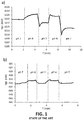
- Figure 1a shows the results obtained with a REFET the micro-reservoir and micro-channel of which are totally filled with poly(HEMA)-type gel, and which has been previously soaked with a buffer solution with pH 7.
- Figure 1b shows the results obtained with a REFET the micro-reservoir and micro-channel of which are totally filled with the buffer solution with pH 7.
- a reference electrode has been used in order to ensure variations in the potential of the solution with maximum values of 1-2 mV.
- the applied gate voltage shown in the Figures corresponds to that maintained by a drain constant current of 100 ⁇ A and a drain-to-source constant voltage of 0.5 V. In this way, the variations in the transistor's threshold voltage are faithfully reflected in the applied gate voltage.
- the response of the REFET filled with hydrogel has high variations of potential in the order of 10 mV with significant variations in time, while in the case of the REFET without hydrogel it has lower variations of potential in the order of 2 mV and no significant variations in time.
- the present invention concerns an ion sensor based on differential measurement comprising:
- the micro-reservoir and the first micro-channel make up a unit totally or partially filled with a porous material, such as a mesoporous material or a macroporous material.
- a porous material such as a mesoporous material or a macroporous material.
- This porous material forms a single body which covers entirely the gate of the first transistor and at least the base of the first micro-channel.
- This porous material has the capacity of absorbing a reference solution from the first micro-channel and spreading it to the gate of the first transistor, expelling or compressing the air inside the micro-reservoir and the first micro-channel.
- the first ISFET transistor becomes a REFET transistor since its gate is in contact with the reference solution, and therefore its measurement remains constant and independent from the ion concentration in the solution to be measured.
- This solution to be measured is measured with the second ISFET.
- the response to the ion concentration of the potential of the electrode used to polarize the ISFET and REFET transistors does not interfere with the sensor's differential response because the measurement is performed in a differential way.
- the gate of the first ion-sensitive field-effect transistor is coated with a membrane which is sensitive to at least one type of ion.
- the transistor will respond to a specific type of ion (for instance: lithium ion, calcium ion, potassium ion).
- ISFETs coated with an ion-sensitive membrane are commonly known as CHEMFETs.
- An example is the PVC membrane containing valinomycin as ion-exchanger material, which is sensitive to potassium (K + ) ions, but there also exist membranes sensitive to other ions such as Ca2 + , Na + , Cl - , NH4 + , Li + .
- the micro-reservoir may be connected to the outside by a second micro-channel.
- the micro-reservoir, the first micro-channel and the second micro-channel make up a unit totally or partially filled with a porous material, forming a single body which covers entirely the gate of the first transistor and at least the base of one of the micro-channels.
- the micro-reservoir and the first micro-channel are completely filled with a porous material, and the second micro-channel is totally or partially free of porous material to expel the air remaining inside the unit made up by the micro-reservoir and the micro-channel.
- the micro-reservoir and the first micro-channel are completely filled with a porous material, and the second micro-channel is empty, keeping the unit partially filled.
- this solution is absorbed by the first micro-channel and spread to the gate of the REFET transistor, expelling the air inside the first micro-channel and the micro-reservoir through the second micro-channel.
- the unit is an alternative unit which is made up only by the micro-reservoir and the first micro-channel; i.e. the micro-reservoir is not connected to the outside through a second micro-channel.
- This alternative unit is completely filled with porous material.
- the layout of the REFET gate inside the micro-reservoir must be such that it remains in contact with the part filled with the reference solution. This configuration facilitates production.
- an ion measuring device comprising a container susceptible to be in contact with a medium for measuring its ion concentration.
- This container comprises:
- the porous material occupies between 5% and 95% of the total volume of the unit made up by the micro-reservoir and the micro-channel or micro-channels, keeping the REFET transistor gate and at least the base of one of the micro-channels in contact with the porous material.
- this porous material has a pore size between 0,01 ⁇ m and 100 ⁇ m. More specifically, this porous material is the result of evaporating, inside the unit made up by the micro-reservoir and the micro-channel, an aqueous suspension containing 10% by weight of alumina particles the diameter of which ranges between 0,01 ⁇ m and 100 ⁇ m. When this suspension evaporates, it is generated the porous material with pores ranging between 0,01 ⁇ m and 100 ⁇ m that fills partially the abovementioned micro-reservoir and micro-channel.
- the porous material can be selected among, for example, alumina, silicon oxide, cellulose, polyamide, polystyrene.
- the porous material is alumina.
- the porous material comprises a number of pillars forming a single body as a kind of matrix. More specifically, these pillars have a diameter ranging between 0,01 ⁇ m and 100 ⁇ m, and are separated from each other by a distance ranging between 0,01 ⁇ m and 100 ⁇ m.
- these pillars are made using micromachining techniques, for example, using photolithography processes with photosensitive materials.
- these pillars can be micromachined directly on the unit made up by the micro-reservoir and the micro-channel, so facilitating the production of the ion sensor.
- This range in the pore size and/or in the separation between pillars prevents the generation of the Donnan potential, while ensuring a flow of reference solution by capillarity enough to expel the air inside the micro-reservoir and the micro-channel and to fill them partially with the reference solution in less than one minute.
- the porous material must be hydrophilic, i.e. it must have a contact angle lower than 90°. If the porous material does not have a contact angle lower than 90°, in that case it can be obtained by means of some known treatment, such as activating the surfaces of the porous material in oxygen plasma, and/or coating these surfaces with molecules containing ionizable functional groups in aqueous solution, for example, 3-aminopropyl triethoxysilane.
- This porous and hydrophilic material unlike other porous materials with smaller pore sizes, prevent the formation of the Donnan potential, and therefore it presents no potential difference between the inside of the pores and the solution to be measured into which the sensor is immersed during the measurement performance. So, even existing a liquid junction between the reference solution and the solution to be measured, the errors in the measurement are not greater than those obtained with a REFET that has all the volume inside the micro-reservoir and the micro-channel filled solely with reference solution. In this way, due to its hydrophilic properties, it allows the micro-reservoir to fill partially or totally with the reference solution quickly. Therefore, it presents a more accurate measurement than the ISFET-REFET sensor the micro-reservoir of which is filled with gel.
- Another advantage of this invention is due to the fact that the porous material is highly hydrophilic, and so it takes longer, compared with the REFET filled solely with reference solution, to dry out if the sensor is left out of the reference solution.
- This sensor also allows being immersed into the reference solution to recalibrate the sensor and to return the ion concentration in the micro-reservoir and the microchannel, or micro-channels, to its level prior to the performance of the measurements.
- Another advantage of the present invention is the fact that, unlike the sensors with porous membranes to create the liquid junction between the inside and the outside of the micro-reservoir, as the document US4874499 expounds, the sensor of the present invention allows an easier filling of the micro-reservoir, since by simply immersing the sensor into the reference solution, it flows by capillarity and fills partially or totally the reservoir.
- a porous membrane like the one described in the aforementioned document is not in contact with the gate of the second sensor and does not fill partially nor totally the micro-reservoir of the second reference sensor.
- the document US4874499 mentions the need of additional micro-channels to fill the sensor. In this case, the filling does not occur by capillarity, and an active system is needed to pump the reference solution into the micro-reservoir.
- this sensor presents no relevant interferences in the ion concentration measurement, presents no air bubble formation in the REFET gate, can be rehydrated quickly, and has a longer useful life.
- the ion sensor (1) based on differential measurement consists of a substrate (2) with connecting tracks (3, 3') and one electrode (4).
- ISFET transistors (5, 5') with their respective gates (6, 6'), being both connected to the connecting tracks (3, 3') by means of bondable wires (7, 7').
- the first ISFET transistor (5) is covered by a structure forming a micro-reservoir (8) on its gate (6) and is connected to the outside by a micro-channel (9).
- the micro-reservoir (8) and the micro-channel (9) make up a REFET transistor (10) which measures a reference solution (12), while the other ISFET transistor (5) measures a solution to be measured.
- the sensor (1) compares the potential difference between both measurements to know the ion concentration in the solution to be measured.
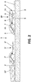
- the sensor (1) comprises a polymeric encapsulating material (15, 15') covering completely the aforementioned connecting tracks (3, 3') and the wires (7, 7').
- This encapsulating material (15') covers partially the ISFET transistor (5'), keeping its gate (6') uncovered.
- the encapsulating material (15) only covers the area where the bondable wire (7) is linked to the REFET transistor (10).
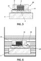
- FIG 3 shows in greater detail the REFET transistor (10); in particular the micro-reservoir (8) and the micro-channel (9) make up a unit partially filled with a porous material (11).
- This porous material (11) forms a single body which covers entirely the gate (6) of the ISFET transistor (5) and the base of the micro-channel (9).
- This porous material (11) comprises alumina particles forming a number of pores with a diameter of 0,05 ⁇ m. Additionally, the porous material (11) occupies 10% of the total volume of the unit made up by the micro-reservoir (8) and the micro-channel (9).
- FIG 4 shows schematically, when the sensor (1) is immersed into the reference solution (12), the porous material (11) absorbs the reference solution (12) by capillarity through the micro-channel (9) and spreads it to the gate (6) that forms part of the REFET (10).
- the air (14) occupying the unit of the micro-reservoir (8) and the micro-channel (9) is expelled through the zone free of porous material (11).
- the micro-reservoir (8) incorporates an additional micro-channel (13) to allow the exit of the air (14) that accumulates inside the micro-reservoir (8).
- the micro-reservoir (8) and the micro-channels (9, 13) make up a unit partially filled with the porous material (11) forming a single body.
- the porous material occupies the entirety of the micro-reservoir (8) and the first micro-channel (9) and leaves exposed the entirety of the second micro-channel (13).
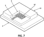
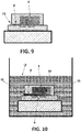
- the porous material (11') comprises a number of pillars forming a single body as a kind of matrix on the unit made up by the micro-reservoir (8) and the micro-channel (9). These pillars have been micromachined using lithography directly on the structure of the micro-reservoir (8), have a diameter of 10 ⁇ m, and are separated from each other by a distance of 10 ⁇ m.
- the micro-reservoir (8) and the first micro-channel (9) are totally filled with porous material (11) and there is no second micro-channel.
- FIG. 10 shows, when the sensor (1) is immersed into a reference solution (12), the porous material (11) absorbs the reference solution (12) by capillarity through the micro-channel (9) and spreads it to the gate (6) of the REFET (10). Instantaneously, the air (14) occupying the unit of the micro-reservoir (8) and the first micro-channel (9) is compressed inside the micro-reservoir (8).
Landscapes
- Life Sciences & Earth Sciences (AREA)
- Chemical & Material Sciences (AREA)
- Health & Medical Sciences (AREA)
- Physics & Mathematics (AREA)
- Molecular Biology (AREA)
- Chemical Kinetics & Catalysis (AREA)
- Electrochemistry (AREA)
- Analytical Chemistry (AREA)
- Biochemistry (AREA)
- General Health & Medical Sciences (AREA)
- General Physics & Mathematics (AREA)
- Immunology (AREA)
- Pathology (AREA)
- Microelectronics & Electronic Packaging (AREA)
- Engineering & Computer Science (AREA)
- Investigating Or Analyzing Materials By The Use Of Electric Means (AREA)
Applications Claiming Priority (2)
| Application Number | Priority Date | Filing Date | Title |
|---|---|---|---|
| ES201531018A ES2597129B1 (es) | 2015-07-13 | 2015-07-13 | Sensor de iones de medida diferencial |
| PCT/ES2016/070527 WO2017009510A1 (es) | 2015-07-13 | 2016-07-12 | Sensor de iones de medida diferencial |
Publications (2)
| Publication Number | Publication Date |
|---|---|
| EP3324177A1 EP3324177A1 (en) | 2018-05-23 |
| EP3324177B1 true EP3324177B1 (en) | 2019-12-18 |
Family
ID=57104055
Family Applications (1)
| Application Number | Title | Priority Date | Filing Date |
|---|---|---|---|
| EP16778071.7A Active EP3324177B1 (en) | 2015-07-13 | 2016-07-12 | Differential ion sensor |
Country Status (7)
| Country | Link |
|---|---|
| US (1) | US10254243B2 (enExample) |
| EP (1) | EP3324177B1 (enExample) |
| JP (1) | JP2018520355A (enExample) |
| KR (1) | KR20180029044A (enExample) |
| CN (1) | CN107850565B (enExample) |
| ES (2) | ES2597129B1 (enExample) |
| WO (1) | WO2017009510A1 (enExample) |
Families Citing this family (1)
| Publication number | Priority date | Publication date | Assignee | Title |
|---|---|---|---|---|
| CN114720538B (zh) * | 2022-04-20 | 2025-02-25 | 陕西科技大学 | 一种水凝胶表面Zeta电位测试装置及其工作方法 |
Family Cites Families (13)
| Publication number | Priority date | Publication date | Assignee | Title |
|---|---|---|---|---|
| EP0155725A1 (en) * | 1984-02-27 | 1985-09-25 | Sentron v.o.f. | Ion concentration measurement system that employs measuring and reference field effect transistor electrodes sensitive to the same ion |
| JPS61237048A (ja) * | 1985-04-12 | 1986-10-22 | Kuraray Co Ltd | 化学物質測定用装置 |
| US4592824A (en) * | 1985-09-13 | 1986-06-03 | Centre Suisse D'electronique Et De Microtechnique S.A. | Miniature liquid junction reference electrode and an integrated solid state electrochemical sensor including the same |
| NL8602669A (nl) * | 1986-10-24 | 1988-05-16 | Sentron V O F | Op een chemfet gebaseerde referentie-elektrode. |
| US4874499A (en) * | 1988-05-23 | 1989-10-17 | Massachusetts Institute Of Technology | Electrochemical microsensors and method of making such sensors |
| GB9913946D0 (en) * | 1999-06-15 | 1999-08-18 | Dart Sensors Ltd | Carbon monoxide sensor |
| GB0509632D0 (en) * | 2005-05-11 | 2005-06-15 | Dart Sensors Ltd | Electrochemical sensors |
| EP2982437B1 (en) * | 2008-06-25 | 2017-12-06 | Life Technologies Corporation | Methods and apparatus for measuring analytes using large scale fet arrays |
| CN102854202A (zh) * | 2011-06-30 | 2013-01-02 | 物思科技发展(北京)有限公司 | 静态物质能量测试系统 |
| EP2753923B8 (en) * | 2011-09-06 | 2017-12-20 | pHase2 Microtechnologies Inc. | Measurement device with sensor array |
| CN103165447B (zh) * | 2011-12-08 | 2016-08-10 | 中芯国际集成电路制造(上海)有限公司 | 鳍式场效应晶体管及其制作方法 |
| US8963216B2 (en) * | 2013-03-13 | 2015-02-24 | Life Technologies Corporation | Chemical sensor with sidewall spacer sensor surface |
| ES2542927R1 (es) * | 2014-02-11 | 2015-09-09 | Consejo Superior De Investigaciones Científicas (Csic) | Sensor de iones basado en medida diferencial, método de fabricación y método de medida |
-
2015
- 2015-07-13 ES ES201531018A patent/ES2597129B1/es not_active Expired - Fee Related
-
2016
- 2016-07-12 CN CN201680039437.3A patent/CN107850565B/zh active Active
- 2016-07-12 US US15/743,923 patent/US10254243B2/en active Active
- 2016-07-12 JP JP2018500661A patent/JP2018520355A/ja active Pending
- 2016-07-12 ES ES16778071T patent/ES2778650T3/es active Active
- 2016-07-12 EP EP16778071.7A patent/EP3324177B1/en active Active
- 2016-07-12 WO PCT/ES2016/070527 patent/WO2017009510A1/es not_active Ceased
- 2016-07-12 KR KR1020187001495A patent/KR20180029044A/ko not_active Withdrawn
Non-Patent Citations (1)
| Title |
|---|
| None * |
Also Published As
| Publication number | Publication date |
|---|---|
| ES2597129B1 (es) | 2017-11-08 |
| KR20180029044A (ko) | 2018-03-19 |
| CN107850565A (zh) | 2018-03-27 |
| US20180209933A1 (en) | 2018-07-26 |
| WO2017009510A1 (es) | 2017-01-19 |
| ES2778650T3 (es) | 2020-08-11 |
| EP3324177A1 (en) | 2018-05-23 |
| US10254243B2 (en) | 2019-04-09 |
| JP2018520355A (ja) | 2018-07-26 |
| CN107850565B (zh) | 2020-03-20 |
| ES2597129A1 (es) | 2017-01-16 |
Similar Documents
| Publication | Publication Date | Title |
|---|---|---|
| JP3151342B2 (ja) | ガスセンサ | |
| CN102265147B (zh) | 参考电极 | |
| García et al. | Comparison of surfactants for dynamic surface modification of poly (dimethylsiloxane) microchips | |
| US8961758B2 (en) | Ion-selective electrode | |
| US10895548B2 (en) | Reference electrode with a pore membrane | |
| EP3106865B1 (en) | Ion sensor based on differential measurement, and production method | |
| RU2613199C2 (ru) | Датчик для растворимого в жидкости газа | |
| US10247692B2 (en) | Reference electrode assembly for electrochemical sensor and electrochemical sensor | |
| EP3324177B1 (en) | Differential ion sensor | |
| US4366038A (en) | Method of casting in place an ion-sensitive membrane and ion-sensitive electrode using said membrane | |
| US5385659A (en) | Reference electrode | |
| US20160195491A1 (en) | Ion selective electrode | |
| KR20240008830A (ko) | 중합체성 막 기반의 고체 기준 전극 | |
| US4981567A (en) | Lithium-salt reference half-cell for potentiometric determinations | |
| EP2885633B1 (en) | Method of measuring ion concentration of an analyte using a micro machined chip of an ion-selective sensor | |
| US20140174923A1 (en) | Ion selective electrode | |
| JP2009156670A (ja) | 比較電極 | |
| Wang et al. | Self-Calibrated Ion-Selective Electrodes | |
| Kahlert | Micro-reference electrodes | |
| EP3336528A1 (en) | Ion-selective electrode | |
| BRPI1002109B1 (pt) | Célula para medição secundária de ph de um fluido e processo para realizar a medição |
Legal Events
| Date | Code | Title | Description |
|---|---|---|---|
| STAA | Information on the status of an ep patent application or granted ep patent |
Free format text: STATUS: UNKNOWN |
|
| STAA | Information on the status of an ep patent application or granted ep patent |
Free format text: STATUS: THE INTERNATIONAL PUBLICATION HAS BEEN MADE |
|
| PUAI | Public reference made under article 153(3) epc to a published international application that has entered the european phase |
Free format text: ORIGINAL CODE: 0009012 |
|
| STAA | Information on the status of an ep patent application or granted ep patent |
Free format text: STATUS: REQUEST FOR EXAMINATION WAS MADE |
|
| 17P | Request for examination filed |
Effective date: 20180117 |
|
| AK | Designated contracting states |
Kind code of ref document: A1 Designated state(s): AL AT BE BG CH CY CZ DE DK EE ES FI FR GB GR HR HU IE IS IT LI LT LU LV MC MK MT NL NO PL PT RO RS SE SI SK SM TR |
|
| AX | Request for extension of the european patent |
Extension state: BA ME |
|
| DAV | Request for validation of the european patent (deleted) | ||
| DAX | Request for extension of the european patent (deleted) | ||
| GRAP | Despatch of communication of intention to grant a patent |
Free format text: ORIGINAL CODE: EPIDOSNIGR1 |
|
| STAA | Information on the status of an ep patent application or granted ep patent |
Free format text: STATUS: GRANT OF PATENT IS INTENDED |
|
| INTG | Intention to grant announced |
Effective date: 20190709 |
|
| GRAS | Grant fee paid |
Free format text: ORIGINAL CODE: EPIDOSNIGR3 |
|
| GRAA | (expected) grant |
Free format text: ORIGINAL CODE: 0009210 |
|
| STAA | Information on the status of an ep patent application or granted ep patent |
Free format text: STATUS: THE PATENT HAS BEEN GRANTED |
|
| AK | Designated contracting states |
Kind code of ref document: B1 Designated state(s): AL AT BE BG CH CY CZ DE DK EE ES FI FR GB GR HR HU IE IS IT LI LT LU LV MC MK MT NL NO PL PT RO RS SE SI SK SM TR |
|
| REG | Reference to a national code |
Ref country code: CH Ref legal event code: EP |
|
| REG | Reference to a national code |
Ref country code: DE Ref legal event code: R096 Ref document number: 602016026518 Country of ref document: DE |
|
| REG | Reference to a national code |
Ref country code: IE Ref legal event code: FG4D |
|
| REG | Reference to a national code |
Ref country code: AT Ref legal event code: REF Ref document number: 1215172 Country of ref document: AT Kind code of ref document: T Effective date: 20200115 |
|
| REG | Reference to a national code |
Ref country code: NL Ref legal event code: MP Effective date: 20191218 |
|
| PG25 | Lapsed in a contracting state [announced via postgrant information from national office to epo] |
Ref country code: LV Free format text: LAPSE BECAUSE OF FAILURE TO SUBMIT A TRANSLATION OF THE DESCRIPTION OR TO PAY THE FEE WITHIN THE PRESCRIBED TIME-LIMIT Effective date: 20191218 Ref country code: SE Free format text: LAPSE BECAUSE OF FAILURE TO SUBMIT A TRANSLATION OF THE DESCRIPTION OR TO PAY THE FEE WITHIN THE PRESCRIBED TIME-LIMIT Effective date: 20191218 Ref country code: LT Free format text: LAPSE BECAUSE OF FAILURE TO SUBMIT A TRANSLATION OF THE DESCRIPTION OR TO PAY THE FEE WITHIN THE PRESCRIBED TIME-LIMIT Effective date: 20191218 Ref country code: BG Free format text: LAPSE BECAUSE OF FAILURE TO SUBMIT A TRANSLATION OF THE DESCRIPTION OR TO PAY THE FEE WITHIN THE PRESCRIBED TIME-LIMIT Effective date: 20200318 Ref country code: GR Free format text: LAPSE BECAUSE OF FAILURE TO SUBMIT A TRANSLATION OF THE DESCRIPTION OR TO PAY THE FEE WITHIN THE PRESCRIBED TIME-LIMIT Effective date: 20200319 Ref country code: NO Free format text: LAPSE BECAUSE OF FAILURE TO SUBMIT A TRANSLATION OF THE DESCRIPTION OR TO PAY THE FEE WITHIN THE PRESCRIBED TIME-LIMIT Effective date: 20200318 Ref country code: FI Free format text: LAPSE BECAUSE OF FAILURE TO SUBMIT A TRANSLATION OF THE DESCRIPTION OR TO PAY THE FEE WITHIN THE PRESCRIBED TIME-LIMIT Effective date: 20191218 |
|
| REG | Reference to a national code |
Ref country code: LT Ref legal event code: MG4D |
|
| PG25 | Lapsed in a contracting state [announced via postgrant information from national office to epo] |
Ref country code: RS Free format text: LAPSE BECAUSE OF FAILURE TO SUBMIT A TRANSLATION OF THE DESCRIPTION OR TO PAY THE FEE WITHIN THE PRESCRIBED TIME-LIMIT Effective date: 20191218 Ref country code: HR Free format text: LAPSE BECAUSE OF FAILURE TO SUBMIT A TRANSLATION OF THE DESCRIPTION OR TO PAY THE FEE WITHIN THE PRESCRIBED TIME-LIMIT Effective date: 20191218 |
|
| PG25 | Lapsed in a contracting state [announced via postgrant information from national office to epo] |
Ref country code: AL Free format text: LAPSE BECAUSE OF FAILURE TO SUBMIT A TRANSLATION OF THE DESCRIPTION OR TO PAY THE FEE WITHIN THE PRESCRIBED TIME-LIMIT Effective date: 20191218 |
|
| PG25 | Lapsed in a contracting state [announced via postgrant information from national office to epo] |
Ref country code: PT Free format text: LAPSE BECAUSE OF FAILURE TO SUBMIT A TRANSLATION OF THE DESCRIPTION OR TO PAY THE FEE WITHIN THE PRESCRIBED TIME-LIMIT Effective date: 20200513 Ref country code: CZ Free format text: LAPSE BECAUSE OF FAILURE TO SUBMIT A TRANSLATION OF THE DESCRIPTION OR TO PAY THE FEE WITHIN THE PRESCRIBED TIME-LIMIT Effective date: 20191218 Ref country code: RO Free format text: LAPSE BECAUSE OF FAILURE TO SUBMIT A TRANSLATION OF THE DESCRIPTION OR TO PAY THE FEE WITHIN THE PRESCRIBED TIME-LIMIT Effective date: 20191218 Ref country code: EE Free format text: LAPSE BECAUSE OF FAILURE TO SUBMIT A TRANSLATION OF THE DESCRIPTION OR TO PAY THE FEE WITHIN THE PRESCRIBED TIME-LIMIT Effective date: 20191218 Ref country code: NL Free format text: LAPSE BECAUSE OF FAILURE TO SUBMIT A TRANSLATION OF THE DESCRIPTION OR TO PAY THE FEE WITHIN THE PRESCRIBED TIME-LIMIT Effective date: 20191218 |
|
| REG | Reference to a national code |
Ref country code: ES Ref legal event code: FG2A Ref document number: 2778650 Country of ref document: ES Kind code of ref document: T3 Effective date: 20200811 |
|
| PG25 | Lapsed in a contracting state [announced via postgrant information from national office to epo] |
Ref country code: IS Free format text: LAPSE BECAUSE OF FAILURE TO SUBMIT A TRANSLATION OF THE DESCRIPTION OR TO PAY THE FEE WITHIN THE PRESCRIBED TIME-LIMIT Effective date: 20200418 Ref country code: SK Free format text: LAPSE BECAUSE OF FAILURE TO SUBMIT A TRANSLATION OF THE DESCRIPTION OR TO PAY THE FEE WITHIN THE PRESCRIBED TIME-LIMIT Effective date: 20191218 Ref country code: SM Free format text: LAPSE BECAUSE OF FAILURE TO SUBMIT A TRANSLATION OF THE DESCRIPTION OR TO PAY THE FEE WITHIN THE PRESCRIBED TIME-LIMIT Effective date: 20191218 |
|
| REG | Reference to a national code |
Ref country code: DE Ref legal event code: R097 Ref document number: 602016026518 Country of ref document: DE |
|
| REG | Reference to a national code |
Ref country code: AT Ref legal event code: MK05 Ref document number: 1215172 Country of ref document: AT Kind code of ref document: T Effective date: 20191218 |
|
| PLBE | No opposition filed within time limit |
Free format text: ORIGINAL CODE: 0009261 |
|
| STAA | Information on the status of an ep patent application or granted ep patent |
Free format text: STATUS: NO OPPOSITION FILED WITHIN TIME LIMIT |
|
| PG25 | Lapsed in a contracting state [announced via postgrant information from national office to epo] |
Ref country code: DK Free format text: LAPSE BECAUSE OF FAILURE TO SUBMIT A TRANSLATION OF THE DESCRIPTION OR TO PAY THE FEE WITHIN THE PRESCRIBED TIME-LIMIT Effective date: 20191218 |
|
| 26N | No opposition filed |
Effective date: 20200921 |
|
| PG25 | Lapsed in a contracting state [announced via postgrant information from national office to epo] |
Ref country code: AT Free format text: LAPSE BECAUSE OF FAILURE TO SUBMIT A TRANSLATION OF THE DESCRIPTION OR TO PAY THE FEE WITHIN THE PRESCRIBED TIME-LIMIT Effective date: 20191218 Ref country code: SI Free format text: LAPSE BECAUSE OF FAILURE TO SUBMIT A TRANSLATION OF THE DESCRIPTION OR TO PAY THE FEE WITHIN THE PRESCRIBED TIME-LIMIT Effective date: 20191218 |
|
| PG25 | Lapsed in a contracting state [announced via postgrant information from national office to epo] |
Ref country code: IT Free format text: LAPSE BECAUSE OF FAILURE TO SUBMIT A TRANSLATION OF THE DESCRIPTION OR TO PAY THE FEE WITHIN THE PRESCRIBED TIME-LIMIT Effective date: 20191218 |
|
| PG25 | Lapsed in a contracting state [announced via postgrant information from national office to epo] |
Ref country code: PL Free format text: LAPSE BECAUSE OF FAILURE TO SUBMIT A TRANSLATION OF THE DESCRIPTION OR TO PAY THE FEE WITHIN THE PRESCRIBED TIME-LIMIT Effective date: 20191218 Ref country code: MC Free format text: LAPSE BECAUSE OF FAILURE TO SUBMIT A TRANSLATION OF THE DESCRIPTION OR TO PAY THE FEE WITHIN THE PRESCRIBED TIME-LIMIT Effective date: 20191218 |
|
| REG | Reference to a national code |
Ref country code: CH Ref legal event code: PL |
|
| REG | Reference to a national code |
Ref country code: BE Ref legal event code: MM Effective date: 20200731 |
|
| PG25 | Lapsed in a contracting state [announced via postgrant information from national office to epo] |
Ref country code: CH Free format text: LAPSE BECAUSE OF NON-PAYMENT OF DUE FEES Effective date: 20200731 Ref country code: LU Free format text: LAPSE BECAUSE OF NON-PAYMENT OF DUE FEES Effective date: 20200712 Ref country code: LI Free format text: LAPSE BECAUSE OF NON-PAYMENT OF DUE FEES Effective date: 20200731 |
|
| PG25 | Lapsed in a contracting state [announced via postgrant information from national office to epo] |
Ref country code: BE Free format text: LAPSE BECAUSE OF NON-PAYMENT OF DUE FEES Effective date: 20200731 |
|
| PG25 | Lapsed in a contracting state [announced via postgrant information from national office to epo] |
Ref country code: IE Free format text: LAPSE BECAUSE OF NON-PAYMENT OF DUE FEES Effective date: 20200712 |
|
| PG25 | Lapsed in a contracting state [announced via postgrant information from national office to epo] |
Ref country code: TR Free format text: LAPSE BECAUSE OF FAILURE TO SUBMIT A TRANSLATION OF THE DESCRIPTION OR TO PAY THE FEE WITHIN THE PRESCRIBED TIME-LIMIT Effective date: 20191218 Ref country code: MT Free format text: LAPSE BECAUSE OF FAILURE TO SUBMIT A TRANSLATION OF THE DESCRIPTION OR TO PAY THE FEE WITHIN THE PRESCRIBED TIME-LIMIT Effective date: 20191218 Ref country code: CY Free format text: LAPSE BECAUSE OF FAILURE TO SUBMIT A TRANSLATION OF THE DESCRIPTION OR TO PAY THE FEE WITHIN THE PRESCRIBED TIME-LIMIT Effective date: 20191218 |
|
| PG25 | Lapsed in a contracting state [announced via postgrant information from national office to epo] |
Ref country code: MK Free format text: LAPSE BECAUSE OF FAILURE TO SUBMIT A TRANSLATION OF THE DESCRIPTION OR TO PAY THE FEE WITHIN THE PRESCRIBED TIME-LIMIT Effective date: 20191218 |
|
| P01 | Opt-out of the competence of the unified patent court (upc) registered |
Effective date: 20230623 |
|
| PGFP | Annual fee paid to national office [announced via postgrant information from national office to epo] |
Ref country code: ES Payment date: 20250801 Year of fee payment: 10 |
|
| PGFP | Annual fee paid to national office [announced via postgrant information from national office to epo] |
Ref country code: DE Payment date: 20250729 Year of fee payment: 10 |
|
| PGFP | Annual fee paid to national office [announced via postgrant information from national office to epo] |
Ref country code: GB Payment date: 20250728 Year of fee payment: 10 |
|
| PGFP | Annual fee paid to national office [announced via postgrant information from national office to epo] |
Ref country code: FR Payment date: 20250725 Year of fee payment: 10 |