EP3324177B1 - Differential ion sensor - Google Patents
Differential ion sensor Download PDFInfo
- Publication number
- EP3324177B1 EP3324177B1 EP16778071.7A EP16778071A EP3324177B1 EP 3324177 B1 EP3324177 B1 EP 3324177B1 EP 16778071 A EP16778071 A EP 16778071A EP 3324177 B1 EP3324177 B1 EP 3324177B1
- Authority
- EP
- European Patent Office
- Prior art keywords
- micro
- ion
- channel
- porous material
- reservoir
- Prior art date
- Legal status (The legal status is an assumption and is not a legal conclusion. Google has not performed a legal analysis and makes no representation as to the accuracy of the status listed.)
- Active
Links
- 239000011148 porous material Substances 0.000 claims description 54
- 239000012088 reference solution Substances 0.000 claims description 51
- 238000005259 measurement Methods 0.000 claims description 41
- 230000005669 field effect Effects 0.000 claims description 16
- 239000000463 material Substances 0.000 claims description 9
- 239000000758 substrate Substances 0.000 claims description 9
- 239000011159 matrix material Substances 0.000 claims description 4
- 150000002500 ions Chemical class 0.000 description 42
- 239000000243 solution Substances 0.000 description 28
- 239000012528 membrane Substances 0.000 description 18
- 239000000499 gel Substances 0.000 description 11
- 230000015572 biosynthetic process Effects 0.000 description 6
- 239000007788 liquid Substances 0.000 description 6
- -1 hydrogen ions Chemical class 0.000 description 5
- 230000004044 response Effects 0.000 description 5
- PNEYBMLMFCGWSK-UHFFFAOYSA-N aluminium oxide Inorganic materials [O-2].[O-2].[O-2].[Al+3].[Al+3] PNEYBMLMFCGWSK-UHFFFAOYSA-N 0.000 description 4
- 230000008901 benefit Effects 0.000 description 4
- 239000007853 buffer solution Substances 0.000 description 4
- 238000000034 method Methods 0.000 description 4
- VAOCPAMSLUNLGC-UHFFFAOYSA-N metronidazole Chemical compound CC1=NC=C([N+]([O-])=O)N1CCO VAOCPAMSLUNLGC-UHFFFAOYSA-N 0.000 description 3
- BHPQYMZQTOCNFJ-UHFFFAOYSA-N Calcium cation Chemical compound [Ca+2] BHPQYMZQTOCNFJ-UHFFFAOYSA-N 0.000 description 2
- 239000007864 aqueous solution Substances 0.000 description 2
- 229910001424 calcium ion Inorganic materials 0.000 description 2
- 239000011248 coating agent Substances 0.000 description 2
- 238000000576 coating method Methods 0.000 description 2
- 238000009792 diffusion process Methods 0.000 description 2
- 239000011521 glass Substances 0.000 description 2
- 239000000017 hydrogel Substances 0.000 description 2
- 229910001416 lithium ion Inorganic materials 0.000 description 2
- 238000004519 manufacturing process Methods 0.000 description 2
- 238000001139 pH measurement Methods 0.000 description 2
- 239000002245 particle Substances 0.000 description 2
- 238000012360 testing method Methods 0.000 description 2
- WYTZZXDRDKSJID-UHFFFAOYSA-N (3-aminopropyl)triethoxysilane Chemical compound CCO[Si](OCC)(OCC)CCCN WYTZZXDRDKSJID-UHFFFAOYSA-N 0.000 description 1
- HBBGRARXTFLTSG-UHFFFAOYSA-N Lithium ion Chemical compound [Li+] HBBGRARXTFLTSG-UHFFFAOYSA-N 0.000 description 1
- 239000004952 Polyamide Substances 0.000 description 1
- 239000004793 Polystyrene Substances 0.000 description 1
- NPYPAHLBTDXSSS-UHFFFAOYSA-N Potassium ion Chemical compound [K+] NPYPAHLBTDXSSS-UHFFFAOYSA-N 0.000 description 1
- VYPSYNLAJGMNEJ-UHFFFAOYSA-N Silicium dioxide Chemical compound O=[Si]=O VYPSYNLAJGMNEJ-UHFFFAOYSA-N 0.000 description 1
- 108010067973 Valinomycin Proteins 0.000 description 1
- 238000010521 absorption reaction Methods 0.000 description 1
- 230000003213 activating effect Effects 0.000 description 1
- 239000007900 aqueous suspension Substances 0.000 description 1
- QVGXLLKOCUKJST-UHFFFAOYSA-N atomic oxygen Chemical compound [O] QVGXLLKOCUKJST-UHFFFAOYSA-N 0.000 description 1
- 229920002678 cellulose Polymers 0.000 description 1
- 239000001913 cellulose Substances 0.000 description 1
- FCFNRCROJUBPLU-UHFFFAOYSA-N compound M126 Natural products CC(C)C1NC(=O)C(C)OC(=O)C(C(C)C)NC(=O)C(C(C)C)OC(=O)C(C(C)C)NC(=O)C(C)OC(=O)C(C(C)C)NC(=O)C(C(C)C)OC(=O)C(C(C)C)NC(=O)C(C)OC(=O)C(C(C)C)NC(=O)C(C(C)C)OC1=O FCFNRCROJUBPLU-UHFFFAOYSA-N 0.000 description 1
- 230000000694 effects Effects 0.000 description 1
- 239000003822 epoxy resin Substances 0.000 description 1
- 238000001704 evaporation Methods 0.000 description 1
- 125000000524 functional group Chemical group 0.000 description 1
- 239000001257 hydrogen Substances 0.000 description 1
- 229910052739 hydrogen Inorganic materials 0.000 description 1
- 238000010348 incorporation Methods 0.000 description 1
- 238000001459 lithography Methods 0.000 description 1
- 238000012423 maintenance Methods 0.000 description 1
- 239000013335 mesoporous material Substances 0.000 description 1
- 238000005459 micromachining Methods 0.000 description 1
- 239000001301 oxygen Substances 0.000 description 1
- 229910052760 oxygen Inorganic materials 0.000 description 1
- 230000000737 periodic effect Effects 0.000 description 1
- 238000000206 photolithography Methods 0.000 description 1
- 229920002647 polyamide Polymers 0.000 description 1
- 229920000647 polyepoxide Polymers 0.000 description 1
- 229920002223 polystyrene Polymers 0.000 description 1
- 229910001414 potassium ion Inorganic materials 0.000 description 1
- 230000008569 process Effects 0.000 description 1
- 229920005989 resin Polymers 0.000 description 1
- 239000011347 resin Substances 0.000 description 1
- 238000000926 separation method Methods 0.000 description 1
- 229910052814 silicon oxide Inorganic materials 0.000 description 1
- 230000007480 spreading Effects 0.000 description 1
- 239000013589 supplement Substances 0.000 description 1
- 239000000725 suspension Substances 0.000 description 1
- FCFNRCROJUBPLU-DNDCDFAISA-N valinomycin Chemical compound CC(C)[C@@H]1NC(=O)[C@H](C)OC(=O)[C@@H](C(C)C)NC(=O)[C@@H](C(C)C)OC(=O)[C@H](C(C)C)NC(=O)[C@H](C)OC(=O)[C@@H](C(C)C)NC(=O)[C@@H](C(C)C)OC(=O)[C@H](C(C)C)NC(=O)[C@H](C)OC(=O)[C@@H](C(C)C)NC(=O)[C@@H](C(C)C)OC1=O FCFNRCROJUBPLU-DNDCDFAISA-N 0.000 description 1
Images


Classifications
-
- G—PHYSICS
- G01—MEASURING; TESTING
- G01N—INVESTIGATING OR ANALYSING MATERIALS BY DETERMINING THEIR CHEMICAL OR PHYSICAL PROPERTIES
- G01N27/00—Investigating or analysing materials by the use of electric, electrochemical, or magnetic means
- G01N27/26—Investigating or analysing materials by the use of electric, electrochemical, or magnetic means by investigating electrochemical variables; by using electrolysis or electrophoresis
- G01N27/403—Cells and electrode assemblies
- G01N27/414—Ion-sensitive or chemical field-effect transistors, i.e. ISFETS or CHEMFETS
-
- G—PHYSICS
- G01—MEASURING; TESTING
- G01N—INVESTIGATING OR ANALYSING MATERIALS BY DETERMINING THEIR CHEMICAL OR PHYSICAL PROPERTIES
- G01N27/00—Investigating or analysing materials by the use of electric, electrochemical, or magnetic means
- G01N27/26—Investigating or analysing materials by the use of electric, electrochemical, or magnetic means by investigating electrochemical variables; by using electrolysis or electrophoresis
- G01N27/28—Electrolytic cell components
- G01N27/30—Electrodes, e.g. test electrodes; Half-cells
- G01N27/301—Reference electrodes
-
- G—PHYSICS
- G01—MEASURING; TESTING
- G01N—INVESTIGATING OR ANALYSING MATERIALS BY DETERMINING THEIR CHEMICAL OR PHYSICAL PROPERTIES
- G01N27/00—Investigating or analysing materials by the use of electric, electrochemical, or magnetic means
- G01N27/26—Investigating or analysing materials by the use of electric, electrochemical, or magnetic means by investigating electrochemical variables; by using electrolysis or electrophoresis
- G01N27/416—Systems
- G01N27/4166—Systems measuring a particular property of an electrolyte
- G01N27/4167—Systems measuring a particular property of an electrolyte pH
Definitions
- the technical field of the present invention is the measurement of ions, and its more common application is the measurement of pH, i.e. the concentration of hydrogen ions in an aqueous solution.
- the present invention concerns an ion sensor based on differential measurement that compares the concentration of certain ions in a solution to be measured with a reference solution contained in a micro-reservoir.
- ISEs ion-selective electrodes
- these electrodes comprise a selective membrane that generates an electric potential by exchanging the ions in the solution with this membrane.
- selective membranes such as crystalline membranes, glass membranes, or resin membranes.
- these electrodes require an internal reference electrode, that is immersed into a reference solution, and an external electrode immersed into the solution to be measured.
- ISFET ion-sensitive field-effect transistor
- These transistors are based on field-effect transistors and usually comprise three terminals: one gate, one drain and one source. More specifically, these sensors are made on integrated circuitry (chip) and comprise a reference electrode that is not integrated in the chip.
- This sensor varies its threshold voltage according to the ion concentration of the solution where it is immersed into; specifically, it varies its voltage according to the ions in contact with its gate.
- This gate is made of a membrane that is selective to at least one type of ion. So, depending on the chosen membrane, the transistor will respond to a specific type of ion.
- the aforementioned threshold voltage is defined as the minimum voltage difference between the reference electrode and the source required to create a current flow between the source and the drain.
- the aforementioned liquid junction allows a small potential difference between the solution to be measured and the reference solution, and thus the differential measurement of the ISFET and REFET depends chiefly on the response of the ISFET to pH or on the concentration of other ions in the solution to be measured.
- a known example of this embodiment consists on the formation of a micro-reservoir sealed with an epoxy resin containing directly the reference solution, or containing a gel that has previously absorbed this reference solution.
- This micro-reservoir allows the reference solution to keep in contact with the REFET gate.
- a glass capillary tube allows the contact between the reference solution and the solution to be measured.
- ISFET-REFET differential sensor which allows the renewal of the reference solution contained in the micro-reservoir.
- the micro-reservoir and the micro-channel of this sensor are fully filled with a gel coating the ISFET gate that makes up the REFET.
- This configuration prevents the formation of air bubbles in the micro-channel and in the micro-reservoir, and hence it avoids this problem of malfunctioning.
- this ISFET-REFET differential sensor allows being stored dry until its first use, or after several uses.
- the gel is soaked with the reference solution, into which the sensor has been previously immersed, and does the same function as if it contained the reference solution directly, but avoiding the formation of air bubbles in the REFET gate or in the micro-channel, hereinafter referred to as "REFET gate".
- this ISFET-REFET sensor comprises a gel to contain the reference solution inside the micro-reservoir and the micro-channel with the aim of preventing problems with air bubbles and allowing a quick rehydration if the gel gets dry.
- this type of sensor for its correct use, must be first immersed into a reference solution so that the gel can absorb it. Once the REFET is filled with the solution, the calibration can be made in the same reference solution. After this step, measurements are performed to compare the ion concentration in the solution to be measured with the ion concentration in the reference solution. Subsequently, if needed, the sensor can be immersed again into the reference solution of the same type for calibrating again the sensor and for allowing the solution in the micro-reservoir, which may have varied slightly during the measurement, to renew by diffusion through the channel.
- this sensor presents a significant error in the measurement of electric potential. This is due to the fact that additional potential arises between the REFET gate and the ISFET gate. Specifically, this potential arises between the gel and the external solution to be measured. The said potential, known as Donnan potential, which depends on the concentration of the different ions in the solution to be measured, causes an interference in the measurement, and thus reduces the sensor's accuracy.
- Figure 1a shows the results obtained with a REFET the micro-reservoir and micro-channel of which are totally filled with poly(HEMA)-type gel, and which has been previously soaked with a buffer solution with pH 7.
- Figure 1b shows the results obtained with a REFET the micro-reservoir and micro-channel of which are totally filled with the buffer solution with pH 7.
- a reference electrode has been used in order to ensure variations in the potential of the solution with maximum values of 1-2 mV.
- the applied gate voltage shown in the Figures corresponds to that maintained by a drain constant current of 100 ⁇ A and a drain-to-source constant voltage of 0.5 V. In this way, the variations in the transistor's threshold voltage are faithfully reflected in the applied gate voltage.
- the response of the REFET filled with hydrogel has high variations of potential in the order of 10 mV with significant variations in time, while in the case of the REFET without hydrogel it has lower variations of potential in the order of 2 mV and no significant variations in time.
- the present invention concerns an ion sensor based on differential measurement comprising:
- the micro-reservoir and the first micro-channel make up a unit totally or partially filled with a porous material, such as a mesoporous material or a macroporous material.
- a porous material such as a mesoporous material or a macroporous material.
- This porous material forms a single body which covers entirely the gate of the first transistor and at least the base of the first micro-channel.
- This porous material has the capacity of absorbing a reference solution from the first micro-channel and spreading it to the gate of the first transistor, expelling or compressing the air inside the micro-reservoir and the first micro-channel.
- the first ISFET transistor becomes a REFET transistor since its gate is in contact with the reference solution, and therefore its measurement remains constant and independent from the ion concentration in the solution to be measured.
- This solution to be measured is measured with the second ISFET.
- the response to the ion concentration of the potential of the electrode used to polarize the ISFET and REFET transistors does not interfere with the sensor's differential response because the measurement is performed in a differential way.
- the gate of the first ion-sensitive field-effect transistor is coated with a membrane which is sensitive to at least one type of ion.
- the transistor will respond to a specific type of ion (for instance: lithium ion, calcium ion, potassium ion).
- ISFETs coated with an ion-sensitive membrane are commonly known as CHEMFETs.
- An example is the PVC membrane containing valinomycin as ion-exchanger material, which is sensitive to potassium (K + ) ions, but there also exist membranes sensitive to other ions such as Ca2 + , Na + , Cl - , NH4 + , Li + .
- the micro-reservoir may be connected to the outside by a second micro-channel.
- the micro-reservoir, the first micro-channel and the second micro-channel make up a unit totally or partially filled with a porous material, forming a single body which covers entirely the gate of the first transistor and at least the base of one of the micro-channels.
- the micro-reservoir and the first micro-channel are completely filled with a porous material, and the second micro-channel is totally or partially free of porous material to expel the air remaining inside the unit made up by the micro-reservoir and the micro-channel.
- the micro-reservoir and the first micro-channel are completely filled with a porous material, and the second micro-channel is empty, keeping the unit partially filled.
- this solution is absorbed by the first micro-channel and spread to the gate of the REFET transistor, expelling the air inside the first micro-channel and the micro-reservoir through the second micro-channel.
- the unit is an alternative unit which is made up only by the micro-reservoir and the first micro-channel; i.e. the micro-reservoir is not connected to the outside through a second micro-channel.
- This alternative unit is completely filled with porous material.
- the layout of the REFET gate inside the micro-reservoir must be such that it remains in contact with the part filled with the reference solution. This configuration facilitates production.
- an ion measuring device comprising a container susceptible to be in contact with a medium for measuring its ion concentration.
- This container comprises:
- the porous material occupies between 5% and 95% of the total volume of the unit made up by the micro-reservoir and the micro-channel or micro-channels, keeping the REFET transistor gate and at least the base of one of the micro-channels in contact with the porous material.
- this porous material has a pore size between 0,01 ⁇ m and 100 ⁇ m. More specifically, this porous material is the result of evaporating, inside the unit made up by the micro-reservoir and the micro-channel, an aqueous suspension containing 10% by weight of alumina particles the diameter of which ranges between 0,01 ⁇ m and 100 ⁇ m. When this suspension evaporates, it is generated the porous material with pores ranging between 0,01 ⁇ m and 100 ⁇ m that fills partially the abovementioned micro-reservoir and micro-channel.
- the porous material can be selected among, for example, alumina, silicon oxide, cellulose, polyamide, polystyrene.
- the porous material is alumina.
- the porous material comprises a number of pillars forming a single body as a kind of matrix. More specifically, these pillars have a diameter ranging between 0,01 ⁇ m and 100 ⁇ m, and are separated from each other by a distance ranging between 0,01 ⁇ m and 100 ⁇ m.
- these pillars are made using micromachining techniques, for example, using photolithography processes with photosensitive materials.
- these pillars can be micromachined directly on the unit made up by the micro-reservoir and the micro-channel, so facilitating the production of the ion sensor.
- This range in the pore size and/or in the separation between pillars prevents the generation of the Donnan potential, while ensuring a flow of reference solution by capillarity enough to expel the air inside the micro-reservoir and the micro-channel and to fill them partially with the reference solution in less than one minute.
- the porous material must be hydrophilic, i.e. it must have a contact angle lower than 90°. If the porous material does not have a contact angle lower than 90°, in that case it can be obtained by means of some known treatment, such as activating the surfaces of the porous material in oxygen plasma, and/or coating these surfaces with molecules containing ionizable functional groups in aqueous solution, for example, 3-aminopropyl triethoxysilane.
- This porous and hydrophilic material unlike other porous materials with smaller pore sizes, prevent the formation of the Donnan potential, and therefore it presents no potential difference between the inside of the pores and the solution to be measured into which the sensor is immersed during the measurement performance. So, even existing a liquid junction between the reference solution and the solution to be measured, the errors in the measurement are not greater than those obtained with a REFET that has all the volume inside the micro-reservoir and the micro-channel filled solely with reference solution. In this way, due to its hydrophilic properties, it allows the micro-reservoir to fill partially or totally with the reference solution quickly. Therefore, it presents a more accurate measurement than the ISFET-REFET sensor the micro-reservoir of which is filled with gel.
- Another advantage of this invention is due to the fact that the porous material is highly hydrophilic, and so it takes longer, compared with the REFET filled solely with reference solution, to dry out if the sensor is left out of the reference solution.
- This sensor also allows being immersed into the reference solution to recalibrate the sensor and to return the ion concentration in the micro-reservoir and the microchannel, or micro-channels, to its level prior to the performance of the measurements.
- Another advantage of the present invention is the fact that, unlike the sensors with porous membranes to create the liquid junction between the inside and the outside of the micro-reservoir, as the document US4874499 expounds, the sensor of the present invention allows an easier filling of the micro-reservoir, since by simply immersing the sensor into the reference solution, it flows by capillarity and fills partially or totally the reservoir.
- a porous membrane like the one described in the aforementioned document is not in contact with the gate of the second sensor and does not fill partially nor totally the micro-reservoir of the second reference sensor.
- the document US4874499 mentions the need of additional micro-channels to fill the sensor. In this case, the filling does not occur by capillarity, and an active system is needed to pump the reference solution into the micro-reservoir.
- this sensor presents no relevant interferences in the ion concentration measurement, presents no air bubble formation in the REFET gate, can be rehydrated quickly, and has a longer useful life.
- the ion sensor (1) based on differential measurement consists of a substrate (2) with connecting tracks (3, 3') and one electrode (4).
- ISFET transistors (5, 5') with their respective gates (6, 6'), being both connected to the connecting tracks (3, 3') by means of bondable wires (7, 7').
- the first ISFET transistor (5) is covered by a structure forming a micro-reservoir (8) on its gate (6) and is connected to the outside by a micro-channel (9).
- the micro-reservoir (8) and the micro-channel (9) make up a REFET transistor (10) which measures a reference solution (12), while the other ISFET transistor (5) measures a solution to be measured.
- the sensor (1) compares the potential difference between both measurements to know the ion concentration in the solution to be measured.
- the sensor (1) comprises a polymeric encapsulating material (15, 15') covering completely the aforementioned connecting tracks (3, 3') and the wires (7, 7').
- This encapsulating material (15') covers partially the ISFET transistor (5'), keeping its gate (6') uncovered.
- the encapsulating material (15) only covers the area where the bondable wire (7) is linked to the REFET transistor (10).
- FIG 3 shows in greater detail the REFET transistor (10); in particular the micro-reservoir (8) and the micro-channel (9) make up a unit partially filled with a porous material (11).
- This porous material (11) forms a single body which covers entirely the gate (6) of the ISFET transistor (5) and the base of the micro-channel (9).
- This porous material (11) comprises alumina particles forming a number of pores with a diameter of 0,05 ⁇ m. Additionally, the porous material (11) occupies 10% of the total volume of the unit made up by the micro-reservoir (8) and the micro-channel (9).
- FIG 4 shows schematically, when the sensor (1) is immersed into the reference solution (12), the porous material (11) absorbs the reference solution (12) by capillarity through the micro-channel (9) and spreads it to the gate (6) that forms part of the REFET (10).
- the air (14) occupying the unit of the micro-reservoir (8) and the micro-channel (9) is expelled through the zone free of porous material (11).
- the micro-reservoir (8) incorporates an additional micro-channel (13) to allow the exit of the air (14) that accumulates inside the micro-reservoir (8).
- the micro-reservoir (8) and the micro-channels (9, 13) make up a unit partially filled with the porous material (11) forming a single body.
- the porous material occupies the entirety of the micro-reservoir (8) and the first micro-channel (9) and leaves exposed the entirety of the second micro-channel (13).
- the porous material (11') comprises a number of pillars forming a single body as a kind of matrix on the unit made up by the micro-reservoir (8) and the micro-channel (9). These pillars have been micromachined using lithography directly on the structure of the micro-reservoir (8), have a diameter of 10 ⁇ m, and are separated from each other by a distance of 10 ⁇ m.
- the micro-reservoir (8) and the first micro-channel (9) are totally filled with porous material (11) and there is no second micro-channel.
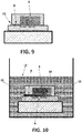
- FIG. 10 shows, when the sensor (1) is immersed into a reference solution (12), the porous material (11) absorbs the reference solution (12) by capillarity through the micro-channel (9) and spreads it to the gate (6) of the REFET (10). Instantaneously, the air (14) occupying the unit of the micro-reservoir (8) and the first micro-channel (9) is compressed inside the micro-reservoir (8).
Landscapes
- Chemical & Material Sciences (AREA)
- Life Sciences & Earth Sciences (AREA)
- Health & Medical Sciences (AREA)
- Biochemistry (AREA)
- Chemical Kinetics & Catalysis (AREA)
- Electrochemistry (AREA)
- Physics & Mathematics (AREA)
- Analytical Chemistry (AREA)
- Molecular Biology (AREA)
- General Health & Medical Sciences (AREA)
- General Physics & Mathematics (AREA)
- Immunology (AREA)
- Pathology (AREA)
- Engineering & Computer Science (AREA)
- Microelectronics & Electronic Packaging (AREA)
- Investigating Or Analyzing Materials By The Use Of Electric Means (AREA)
Description
- The technical field of the present invention is the measurement of ions, and its more common application is the measurement of pH, i.e. the concentration of hydrogen ions in an aqueous solution.
- The present invention concerns an ion sensor based on differential measurement that compares the concentration of certain ions in a solution to be measured with a reference solution contained in a micro-reservoir.
- Currently, several techniques are known for performing the measurement of ion concentrations in a medium.
- One of the most used techniques is the measurement with ion-selective electrodes (ISEs). More specifically, these electrodes comprise a selective membrane that generates an electric potential by exchanging the ions in the solution with this membrane. Currently, several types of selective membranes are known, such as crystalline membranes, glass membranes, or resin membranes. To perform the measurement of the electric potential, these electrodes require an internal reference electrode, that is immersed into a reference solution, and an external electrode immersed into the solution to be measured.
- Another type of widely known sensors are the ion-sensitive field-effect transistor (ISFET) sensors. These transistors are based on field-effect transistors and usually comprise three terminals: one gate, one drain and one source. More specifically, these sensors are made on integrated circuitry (chip) and comprise a reference electrode that is not integrated in the chip. This sensor varies its threshold voltage according to the ion concentration of the solution where it is immersed into; specifically, it varies its voltage according to the ions in contact with its gate. This gate is made of a membrane that is selective to at least one type of ion. So, depending on the chosen membrane, the transistor will respond to a specific type of ion. The aforementioned threshold voltage is defined as the minimum voltage difference between the reference electrode and the source required to create a current flow between the source and the drain.
- Both the sensors based on ISE electrodes and the sensors based on ISFET require a reference electrode, which is not integrated in the sensor, to measure ions. Hence, they are expensive to produce and need periodic maintenance.
- Finally, there is an alternative way to perform the measurement of pH that requires no reference electrodes and that includes two ISFET transistors. In particular, one of the ISFET performs the ion measurement in the solution to be measured through its gate. Meanwhile, the gate of the other ISFET, which is sensitive to pH, remains exposed to a constant pH concentration with the incorporation of a structure covering the gate as a kind of micro-reservoir. This micro-reservoir is filled with a reference solution, which is a buffer solution at a specific pH level, and is connected to the outside, i.e. with the solution to be measured, by a micro-channel through which a liquid junction between the two solutions occurs. In this way, we obtain a reference ISFET transistor, commonly known as REFET.
- Specifically, the aforementioned liquid junction allows a small potential difference between the solution to be measured and the reference solution, and thus the differential measurement of the ISFET and REFET depends chiefly on the response of the ISFET to pH or on the concentration of other ions in the solution to be measured.
- A known example of this embodiment consists on the formation of a micro-reservoir sealed with an epoxy resin containing directly the reference solution, or containing a gel that has previously absorbed this reference solution. This micro-reservoir allows the reference solution to keep in contact with the REFET gate. Additionally, a glass capillary tube allows the contact between the reference solution and the solution to be measured.
- The problem with this type of sensors is its useful life, as it depends on the volume of the micro-reservoir and the volume of the micro-channel. This is due to the fact that the reference solution in the micro-reservoir will be diluted and/or contaminated through the micro-channel, and so the error in the measurement will increase progressively as the pH level inside the micro-reservoir is no longer properly buffered and varies more strikingly during the performance of the measurement. For this reason it is considered a sensor with short useful life.
- Another problem with this type of sensor is that when it is stored in a dry environment for a long period of time, the reference solution in the micro-reservoir evaporates slowly through the micro-channel and is replaced by air. Consequently, either the reference solution evaporates completely or air bubbles appear in the reference solution when the sensor is immersed again into the solution to be measured, hampering the sensor to work properly. For example, if the air bubbles remain in the surface of the REFET gate, or if they jam in the micro-channel obstructing the liquid junction between the outside and the inside of the micro-reservoir, the measurement of the sensor will be incorrect.
- To solve these problems, there is another type of ISFET-REFET differential sensor which allows the renewal of the reference solution contained in the micro-reservoir. To that end, the micro-reservoir and the micro-channel of this sensor are fully filled with a gel coating the ISFET gate that makes up the REFET. This configuration prevents the formation of air bubbles in the micro-channel and in the micro-reservoir, and hence it avoids this problem of malfunctioning. Besides, this ISFET-REFET differential sensor allows being stored dry until its first use, or after several uses.
- More specifically, the gel is soaked with the reference solution, into which the sensor has been previously immersed, and does the same function as if it contained the reference solution directly, but avoiding the formation of air bubbles in the REFET gate or in the micro-channel, hereinafter referred to as "REFET gate".
- That is, this ISFET-REFET sensor comprises a gel to contain the reference solution inside the micro-reservoir and the micro-channel with the aim of preventing problems with air bubbles and allowing a quick rehydration if the gel gets dry.
- In particular, this type of sensor, for its correct use, must be first immersed into a reference solution so that the gel can absorb it. Once the REFET is filled with the solution, the calibration can be made in the same reference solution. After this step, measurements are performed to compare the ion concentration in the solution to be measured with the ion concentration in the reference solution. Subsequently, if needed, the sensor can be immersed again into the reference solution of the same type for calibrating again the sensor and for allowing the solution in the micro-reservoir, which may have varied slightly during the measurement, to renew by diffusion through the channel.
- Despite these advantages, this sensor presents a significant error in the measurement of electric potential. This is due to the fact that additional potential arises between the REFET gate and the ISFET gate. Specifically, this potential arises between the gel and the external solution to be measured. The said potential, known as Donnan potential, which depends on the concentration of the different ions in the solution to be measured, causes an interference in the measurement, and thus reduces the sensor's accuracy.
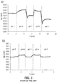
- The abovementioned interferences are evidenced in
Figure 1a and Figure 1b , where two ISFET-REFET differential sensors have been immersed into two buffer solutions withpH 7 andpH 4. In particular,Figure 1a shows the results obtained with a REFET the micro-reservoir and micro-channel of which are totally filled with poly(HEMA)-type gel, and which has been previously soaked with a buffer solution withpH 7. In contrast,Figure 1b shows the results obtained with a REFET the micro-reservoir and micro-channel of which are totally filled with the buffer solution withpH 7. - To apply the gate voltage of both REFETs, a reference electrode has been used in order to ensure variations in the potential of the solution with maximum values of 1-2 mV. The applied gate voltage shown in the Figures corresponds to that maintained by a drain constant current of 100 µA and a drain-to-source constant voltage of 0.5 V. In this way, the variations in the transistor's threshold voltage are faithfully reflected in the applied gate voltage.
- As shown in
Figures 1a and 1b , the response of the REFET filled with hydrogel has high variations of potential in the order of 10 mV with significant variations in time, while in the case of the REFET without hydrogel it has lower variations of potential in the order of 2 mV and no significant variations in time. - There exists also, according to what is described in the document
US4874499 , a sensor with a configuration made up of a first ion sensor comprising an ion-sensitive membrane in the opening of a cavity in the first sensor, and a second sensor that acts as REFET with a porous membrane providing an opening in the cavity of the second sensor -the aim of this porous membrane is to allow a liquid junction between the inside and the outside of the cavity. - The present invention concerns an ion sensor based on differential measurement comprising:
- a substrate with at least one connecting track;
- one electrode linked to the substrate;
- a first ion-sensitive field-effect transistor (ISFET) with one gate, integrated in a first chip inserted in the substrate and linked to at least one connecting track;
- a second ion-sensitive field-effect transistor (ISFET) with one gate, integrated in a second chip inserted in the substrate and linked to at least one connecting track;
- a structure adhered on the first ion-sensitive field-effect transistor, configured to create a micro-reservoir on the gate of the first ISFET transistor;
- at least a first micro-channel connecting the micro-reservoir with the outside and allowing the renewal by diffusion of the reference solution; and
- an encapsulating material to isolate completely the connecting tracks and partially the first and the second ion-sensitive field-effect transistors.
- More specifically, the micro-reservoir and the first micro-channel make up a unit totally or partially filled with a porous material, such as a mesoporous material or a macroporous material. This porous material forms a single body which covers entirely the gate of the first transistor and at least the base of the first micro-channel. This porous material has the capacity of absorbing a reference solution from the first micro-channel and spreading it to the gate of the first transistor, expelling or compressing the air inside the micro-reservoir and the first micro-channel.
- In this way, the first ISFET transistor becomes a REFET transistor since its gate is in contact with the reference solution, and therefore its measurement remains constant and independent from the ion concentration in the solution to be measured. This solution to be measured is measured with the second ISFET. The response to the ion concentration of the potential of the electrode used to polarize the ISFET and REFET transistors does not interfere with the sensor's differential response because the measurement is performed in a differential way.
- Optionally, the gate of the first ion-sensitive field-effect transistor (ISFET) is coated with a membrane which is sensitive to at least one type of ion. In this way, depending on the chosen membrane, the transistor will respond to a specific type of ion (for instance: lithium ion, calcium ion, potassium ion). These ISFETs coated with an ion-sensitive membrane are commonly known as CHEMFETs. An example is the PVC membrane containing valinomycin as ion-exchanger material, which is sensitive to potassium (K+) ions, but there also exist membranes sensitive to other ions such as Ca2+, Na+, Cl-, NH4+, Li+.
- Preferably, the micro-reservoir may be connected to the outside by a second micro-channel. This way, the micro-reservoir, the first micro-channel and the second micro-channel make up a unit totally or partially filled with a porous material, forming a single body which covers entirely the gate of the first transistor and at least the base of one of the micro-channels.
- Preferably, the micro-reservoir and the first micro-channel are completely filled with a porous material, and the second micro-channel is totally or partially free of porous material to expel the air remaining inside the unit made up by the micro-reservoir and the micro-channel.
- Optionally, the micro-reservoir and the first micro-channel are completely filled with a porous material, and the second micro-channel is empty, keeping the unit partially filled. In this way, when the sensor is put into the reference solution, this solution is absorbed by the first micro-channel and spread to the gate of the REFET transistor, expelling the air inside the first micro-channel and the micro-reservoir through the second micro-channel.
- In a variation of the sensor based on differential measurement, the unit is an alternative unit which is made up only by the micro-reservoir and the first micro-channel; i.e. the micro-reservoir is not connected to the outside through a second micro-channel. This alternative unit is completely filled with porous material. In this way, when the sensor is immersed into the reference solution, this solution soaks the porous material generating a pressure inside the micro-reservoir that compresses air so that the micro-reservoir becomes partially filled with the solution. The layout of the REFET gate inside the micro-reservoir must be such that it remains in contact with the part filled with the reference solution. This configuration facilitates production.
- In another aspect of the invention, it is described an ion measuring device comprising a container susceptible to be in contact with a medium for measuring its ion concentration. This container, in turn, comprises:
- the sensor previously described according to any of its variants,
- a control unit, linked to the abovementioned sensor, to calculate the ion concentration of the medium, and
- an indicator unit, linked to the control unit, to indicate visually the ion concentration of the medium to a user.
- Preferably, the porous material occupies between 5% and 95% of the total volume of the unit made up by the micro-reservoir and the micro-channel or micro-channels, keeping the REFET transistor gate and at least the base of one of the micro-channels in contact with the porous material.
- Preferably, this porous material has a pore size between 0,01 µm and 100 µm. More specifically, this porous material is the result of evaporating, inside the unit made up by the micro-reservoir and the micro-channel, an aqueous suspension containing 10% by weight of alumina particles the diameter of which ranges between 0,01 µm and 100 µm. When this suspension evaporates, it is generated the porous material with pores ranging between 0,01 µm and 100 µm that fills partially the abovementioned micro-reservoir and micro-channel.
- Preferably, the porous material can be selected among, for example, alumina, silicon oxide, cellulose, polyamide, polystyrene. Preferably, the porous material is alumina.
- Alternatively, the porous material comprises a number of pillars forming a single body as a kind of matrix. More specifically, these pillars have a diameter ranging between 0,01 µm and 100 µm, and are separated from each other by a distance ranging between 0,01 µm and 100 µm. Preferably, these pillars are made using micromachining techniques, for example, using photolithography processes with photosensitive materials.
- Additionally, these pillars can be micromachined directly on the unit made up by the micro-reservoir and the micro-channel, so facilitating the production of the ion sensor.
- This range in the pore size and/or in the separation between pillars prevents the generation of the Donnan potential, while ensuring a flow of reference solution by capillarity enough to expel the air inside the micro-reservoir and the micro-channel and to fill them partially with the reference solution in less than one minute.
- Additionally, to make possible the absorption of the reference solution by capillarity, the porous material must be hydrophilic, i.e. it must have a contact angle lower than 90°. If the porous material does not have a contact angle lower than 90°, in that case it can be obtained by means of some known treatment, such as activating the surfaces of the porous material in oxygen plasma, and/or coating these surfaces with molecules containing ionizable functional groups in aqueous solution, for example, 3-aminopropyl triethoxysilane.
- This porous and hydrophilic material, unlike other porous materials with smaller pore sizes, prevent the formation of the Donnan potential, and therefore it presents no potential difference between the inside of the pores and the solution to be measured into which the sensor is immersed during the measurement performance. So, even existing a liquid junction between the reference solution and the solution to be measured, the errors in the measurement are not greater than those obtained with a REFET that has all the volume inside the micro-reservoir and the micro-channel filled solely with reference solution. In this way, due to its hydrophilic properties, it allows the micro-reservoir to fill partially or totally with the reference solution quickly. Therefore, it presents a more accurate measurement than the ISFET-REFET sensor the micro-reservoir of which is filled with gel.
- Another advantage of this invention is due to the fact that the porous material is highly hydrophilic, and so it takes longer, compared with the REFET filled solely with reference solution, to dry out if the sensor is left out of the reference solution.
- Additionally, in the event that it dries out completely, it can be easily and quickly rehydrated by immersing it again into the reference solution, without risk of bubble formation, hence its useful life is longer in comparison with the sensors described in the state of the art. This sensor also allows being immersed into the reference solution to recalibrate the sensor and to return the ion concentration in the micro-reservoir and the microchannel, or micro-channels, to its level prior to the performance of the measurements.
- Another advantage of the present invention is the fact that, unlike the sensors with porous membranes to create the liquid junction between the inside and the outside of the micro-reservoir, as the document
US4874499 expounds, the sensor of the present invention allows an easier filling of the micro-reservoir, since by simply immersing the sensor into the reference solution, it flows by capillarity and fills partially or totally the reservoir. A porous membrane like the one described in the aforementioned document is not in contact with the gate of the second sensor and does not fill partially nor totally the micro-reservoir of the second reference sensor. The documentUS4874499 mentions the need of additional micro-channels to fill the sensor. In this case, the filling does not occur by capillarity, and an active system is needed to pump the reference solution into the micro-reservoir. - In summary, thanks to this characteristic configuration, this sensor presents no relevant interferences in the ion concentration measurement, presents no air bubble formation in the REFET gate, can be rehydrated quickly, and has a longer useful life.
- In order to supplement the description now being given, and with the aim of contributing to a better understanding of the characteristics of the invention according to a preferred practical embodiment, the present description is accompanied, as an integral part thereof, by a set of drawings provided for illustrative non-limiting purposes, in which:
-
Figure 1a shows a chart of the results obtained from the measurement with a REFET filled with poly(HEMA)-type gel, according to a solution known in the state of the art. -
Figure 1b shows a chart of the results obtained from the measurement with a REFET filled with the reference solution, according to a solution known in the state of the art. -
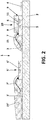
Figure 2 shows a schematic view of the ion sensor based on differential measurement. -
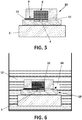
Figure 3 shows a schematic view of the preferred configuration of the REFET. -
Figure 4 shows a schematic view of the REFET in the previous figure immersed into the reference solution. -
Figure 5 shows a schematic view of another preferred configuration of the REFET. -
Figure 6 shows a schematic view of the REFET in the previous figure immersed into the reference solution. -
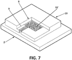
Figure 7 shows a schematic view of another preferred configuration of the REFET, with a partial cut-away showing the inside of the micro-reservoir. -
Figure 8 shows a chart of the results obtained from the measurement with a REFET filled with a porous material. -
Figure 9 shows a schematic view of another preferred configuration of the REFET. -
Figure 10 shows a schematic view of the REFET inFigure 9 immersed into the reference solution. - In a preferred embodiment of the invention, as shown in
Figure 2 , the ion sensor (1) based on differential measurement consists of a substrate (2) with connecting tracks (3, 3') and one electrode (4). - On the aforementioned substrate (2) there are integrated a first and a second ion-sensitive field-effect transistor with one gate which are integrated in a first and a second chip, known as ISFET transistors (5, 5') with their respective gates (6, 6'), being both connected to the connecting tracks (3, 3') by means of bondable wires (7, 7'). More specifically, the first ISFET transistor (5) is covered by a structure forming a micro-reservoir (8) on its gate (6) and is connected to the outside by a micro-channel (9). With this configuration of the ISFET (5), the micro-reservoir (8) and the micro-channel (9) make up a REFET transistor (10) which measures a reference solution (12), while the other ISFET transistor (5) measures a solution to be measured. The sensor (1) compares the potential difference between both measurements to know the ion concentration in the solution to be measured.
- Additionally, the sensor (1) comprises a polymeric encapsulating material (15, 15') covering completely the aforementioned connecting tracks (3, 3') and the wires (7, 7'). This encapsulating material (15') covers partially the ISFET transistor (5'), keeping its gate (6') uncovered. With regard to the REFET transistor (10), the encapsulating material (15) only covers the area where the bondable wire (7) is linked to the REFET transistor (10).
-
Figure 3 shows in greater detail the REFET transistor (10); in particular the micro-reservoir (8) and the micro-channel (9) make up a unit partially filled with a porous material (11). This porous material (11) forms a single body which covers entirely the gate (6) of the ISFET transistor (5) and the base of the micro-channel (9). This porous material (11) comprises alumina particles forming a number of pores with a diameter of 0,05 µm. Additionally, the porous material (11) occupies 10% of the total volume of the unit made up by the micro-reservoir (8) and the micro-channel (9). - Thanks to this configuration, as
Figure 4 shows schematically, when the sensor (1) is immersed into the reference solution (12), the porous material (11) absorbs the reference solution (12) by capillarity through the micro-channel (9) and spreads it to the gate (6) that forms part of the REFET (10). Instantaneously, due to the pressure exerted by the effect of capillarity, the air (14) occupying the unit of the micro-reservoir (8) and the micro-channel (9) is expelled through the zone free of porous material (11). - In another preferred embodiment, shown in
Figure 5 , the micro-reservoir (8) incorporates an additional micro-channel (13) to allow the exit of the air (14) that accumulates inside the micro-reservoir (8). Specifically, the micro-reservoir (8) and the micro-channels (9, 13) make up a unit partially filled with the porous material (11) forming a single body. The porous material occupies the entirety of the micro-reservoir (8) and the first micro-channel (9) and leaves exposed the entirety of the second micro-channel (13). - In this way, as
Figure 6 shows, when the sensor (1) is immersed into a reference solution (12), the porous material (11) absorbs the reference solution (12) by capillarity through the micro-channel (9) and spreads it to the gate (6) of the REFET (10). Instantaneously, the air (14) occupying the unit of the micro-reservoir (8) and the first micro-channel (9) is expelled through the second micro-channel (13), i.e. the zone free of porous material (11). - In another preferred embodiment of the invention, shown in
Figure 7 , the porous material (11') comprises a number of pillars forming a single body as a kind of matrix on the unit made up by the micro-reservoir (8) and the micro-channel (9). These pillars have been micromachined using lithography directly on the structure of the micro-reservoir (8), have a diameter of 10 µm, and are separated from each other by a distance of 10 µm. - With the purpose of demonstration the advantages of the sensor (1), several tests have been carried out. In particular, tests have been made with configurations of micro-reservoir (8) with one micro-channel (9) as the one in
Figure 3 ; two micro-channels (9, 13) as the one represented inFigure 5 ; or with a matrix of pillars as the one inFigure 7 , obtaining the results displayed inFigure 8 . Comparing theFigures 1a, 1b and8 , it can be observed graphically the improvements of the present invention over the state of the art. In this way, the sensor (1) of the present invention presents no interferences in the measurements, which are common in other sensors with gels, and the contribution of the REFET to its response to different pHs is small and stable, comparable to the case of using directly the reference solution (12). - In another preferred embodiment of the sensor (1), as shown in
Figure 9 , the micro-reservoir (8) and the first micro-channel (9) are totally filled with porous material (11) and there is no second micro-channel. - In this way, as
Figure 10 shows, when the sensor (1) is immersed into a reference solution (12), the porous material (11) absorbs the reference solution (12) by capillarity through the micro-channel (9) and spreads it to the gate (6) of the REFET (10). Instantaneously, the air (14) occupying the unit of the micro-reservoir (8) and the first micro-channel (9) is compressed inside the micro-reservoir (8).
Claims (10)
- An ion sensor (1) based on differential measurement comprising:- a substrate (2) with connecting tracks (3, 3');- an electrode (4);- a first ion-sensitive field-effect transistor (5) with one gate (6), integrated in a first chip inserted in the substrate (2) and linked to at least one connecting track (3) of the connecting tracks (3, 3');- a second ion-sensitive field-effect transistor (5') with one gate (6'), integrated in a second chip inserted in the substrate (2) and linked to at least one connecting track (3') of the connecting tracks (3, 3');- a structure adhered on the first ion-sensitive field-effect transistor (5) configured to create a micro-reservoir (8) on the gate (6) of the first ion-sensitive field-effect transistor (5);- a first micro-channel (9) connecting the micro-reservoir (8) with the outside; and- an encapsulating material (15, 15') to isolate completely the connecting tracks (3, 3') and partially the first and the second ion-sensitive field-effect transistors (5, 5'),characterized in that the micro-reservoir (8) and the first micro-channel (9) make up a first unit totally or partially filled with a porous material (11), said porous material (11) forming a first single body which covers entirely the gate (6) of the first ion-sensitive field-effect transistor (5) and at least the base of the first micro-channel (9), and configured to absorb a reference solution (12) from the outside through the first micro-channel (9) to the gate (6) of the first ion-sensitive field-effect transistor (5), expelling or compressing the air (14) inside the first unit.
- The ion sensor (1) based on differential measurement according to claim 1, characterized in that additionally the micro-reservoir (8) is connected to the outside by a second micro-channel (13).
- The ion sensor (1) based on differential measurement according to claim 2, characterized in that the micro-reservoir (8), the first micro-channel (9) and the second micro-channel (13) make up a second unit totally or partially filled with the porous material (11), said porous material (11) forming a second single body which covers entirely the gate (6) of the first ion-sensitive field-effect transistor (5) and at least the base of the first micro-channel (9).
- The ion sensor (1) based on differential measurement according to claim 3, characterized in that the first unit is completely filled with the porous material (11) and the second micro-channel (13) is totally or partially free of porous material (11) to expel the air (14) remaining inside the first unit.
- The ion sensor (1) based on differential measurement according to claim 1, characterized in that the porous material (11) fills between 5% and 95% of the total volume of the first unit.
- The ion sensor (1) based on differential measurement according to claim 3, characterized in that the porous material (11) fills between 5% and 95% of the total volume of the second unit.
- The ion sensor (1) based on differential measurement according to claim 1, characterized in that the porous material (11) has pores with a diameter ranging between 0,01 µm and 100 µm.
- The ion sensor (1) based on differential measurement according to claim 1, characterized in that the porous material (11) comprises a number of pillars forming the first single body as a matrix, where each pillar has a diameter ranging between 0,01 µm and 100 µm, and each pillar is separated from its contiguous pillars by a distance ranging between 0,01 µm and 100 µm.
- The ion sensor (1) based on differential measurement according to claim 1, characterized in that the first unit is totally filled with the porous material (11).
- An ion measuring device comprising a container susceptible to be in contact with a medium for measuring its ion concentration, characterized in that the container comprises:• an ion sensor (1) based on differential measurement according to any of the previous claims,• a control unit, linked to the abovementioned ion sensor (1) based on differential measurement, to calculate the ion concentration of the medium, and• an indicator unit, linked to the control unit, to indicate visually the ion concentration of the medium.
Applications Claiming Priority (2)
| Application Number | Priority Date | Filing Date | Title |
|---|---|---|---|
| ES201531018A ES2597129B1 (en) | 2015-07-13 | 2015-07-13 | ION SENSOR OF DIFFERENTIAL MEASURE |
| PCT/ES2016/070527 WO2017009510A1 (en) | 2015-07-13 | 2016-07-12 | Ion sensor with differential measurement |
Publications (2)
| Publication Number | Publication Date |
|---|---|
| EP3324177A1 EP3324177A1 (en) | 2018-05-23 |
| EP3324177B1 true EP3324177B1 (en) | 2019-12-18 |
Family
ID=57104055
Family Applications (1)
| Application Number | Title | Priority Date | Filing Date |
|---|---|---|---|
| EP16778071.7A Active EP3324177B1 (en) | 2015-07-13 | 2016-07-12 | Differential ion sensor |
Country Status (7)
| Country | Link |
|---|---|
| US (1) | US10254243B2 (en) |
| EP (1) | EP3324177B1 (en) |
| JP (1) | JP2018520355A (en) |
| KR (1) | KR20180029044A (en) |
| CN (1) | CN107850565B (en) |
| ES (2) | ES2597129B1 (en) |
| WO (1) | WO2017009510A1 (en) |
Family Cites Families (13)
| Publication number | Priority date | Publication date | Assignee | Title |
|---|---|---|---|---|
| EP0155725A1 (en) * | 1984-02-27 | 1985-09-25 | Sentron v.o.f. | Ion concentration measurement system that employs measuring and reference field effect transistor electrodes sensitive to the same ion |
| JPS61237048A (en) * | 1985-04-12 | 1986-10-22 | Kuraray Co Ltd | Chemical matarial measuring apparatus |
| US4592824A (en) * | 1985-09-13 | 1986-06-03 | Centre Suisse D'electronique Et De Microtechnique S.A. | Miniature liquid junction reference electrode and an integrated solid state electrochemical sensor including the same |
| NL8602669A (en) * | 1986-10-24 | 1988-05-16 | Sentron V O F | Reference electrode e.g. for catheter tip has cavity for chemfet - as ion-selective electrode in electrolyte and with capillary to outside formed in plate sandwiched between FET substrate and polymer layer |
| US4874499A (en) * | 1988-05-23 | 1989-10-17 | Massachusetts Institute Of Technology | Electrochemical microsensors and method of making such sensors |
| GB9913946D0 (en) * | 1999-06-15 | 1999-08-18 | Dart Sensors Ltd | Carbon monoxide sensor |
| GB0509632D0 (en) * | 2005-05-11 | 2005-06-15 | Dart Sensors Ltd | Electrochemical sensors |
| CN102203282B (en) * | 2008-06-25 | 2014-04-30 | 生命技术公司 | Methods and apparatus for measuring analytes using large scale FET arrays |
| CN102854202A (en) * | 2011-06-30 | 2013-01-02 | 物思科技发展(北京)有限公司 | Test system of energy of static state substance |
| EP2753923B8 (en) * | 2011-09-06 | 2017-12-20 | pHase2 Microtechnologies Inc. | Measurement device with sensor array |
| CN103165447B (en) * | 2011-12-08 | 2016-08-10 | 中芯国际集成电路制造(上海)有限公司 | Fin formula field effect transistor and preparation method thereof |
| US8963216B2 (en) * | 2013-03-13 | 2015-02-24 | Life Technologies Corporation | Chemical sensor with sidewall spacer sensor surface |
| ES2542927R1 (en) * | 2014-02-11 | 2015-09-09 | Consejo Superior De Investigaciones Científicas (Csic) | Ion sensor based on differential measurement, manufacturing method and measurement method |
-
2015
- 2015-07-13 ES ES201531018A patent/ES2597129B1/en not_active Expired - Fee Related
-
2016
- 2016-07-12 WO PCT/ES2016/070527 patent/WO2017009510A1/en active Application Filing
- 2016-07-12 ES ES16778071T patent/ES2778650T3/en active Active
- 2016-07-12 CN CN201680039437.3A patent/CN107850565B/en active Active
- 2016-07-12 JP JP2018500661A patent/JP2018520355A/en active Pending
- 2016-07-12 US US15/743,923 patent/US10254243B2/en active Active
- 2016-07-12 EP EP16778071.7A patent/EP3324177B1/en active Active
- 2016-07-12 KR KR1020187001495A patent/KR20180029044A/en unknown
Non-Patent Citations (1)
| Title |
|---|
| None * |
Also Published As
| Publication number | Publication date |
|---|---|
| WO2017009510A1 (en) | 2017-01-19 |
| CN107850565B (en) | 2020-03-20 |
| KR20180029044A (en) | 2018-03-19 |
| ES2597129A1 (en) | 2017-01-16 |
| US20180209933A1 (en) | 2018-07-26 |
| ES2597129B1 (en) | 2017-11-08 |
| EP3324177A1 (en) | 2018-05-23 |
| ES2778650T3 (en) | 2020-08-11 |
| JP2018520355A (en) | 2018-07-26 |
| CN107850565A (en) | 2018-03-27 |
| US10254243B2 (en) | 2019-04-09 |
Similar Documents
| Publication | Publication Date | Title |
|---|---|---|
| CN107205643B (en) | Sweat sensing with analytical assurance | |
| JP3151342B2 (en) | Gas sensor | |
| García et al. | Comparison of surfactants for dynamic surface modification of poly (dimethylsiloxane) microchips | |
| US3498899A (en) | Electrochemical electrode assembly | |
| US10895548B2 (en) | Reference electrode with a pore membrane | |
| RU2613199C2 (en) | Sensor for fluid-soluble gas | |
| EP3106865B1 (en) | Ion sensor based on differential measurement, and production method | |
| CN110088620A (en) | Sensor module is used for multiple times for body fluid | |
| US3830718A (en) | Ammonia sensor | |
| EP3324177B1 (en) | Differential ion sensor | |
| US4366038A (en) | Method of casting in place an ion-sensitive membrane and ion-sensitive electrode using said membrane | |
| JPH06194334A (en) | Reference electrode | |
| US20160195491A1 (en) | Ion selective electrode | |
| EP2885633B1 (en) | Method of measuring ion concentration of an analyte using a micro machined chip of an ion-selective sensor | |
| US20140174923A1 (en) | Ion selective electrode | |
| JP2009156670A (en) | Comparison electrode | |
| KR102559043B1 (en) | Method of manufacturing sensor for detecting ion and sensor for detecting ion manufactured by the same | |
| US20180172620A1 (en) | Ion-Selective Electrode | |
| Wang et al. | Self-Calibrated Ion-Selective Electrodes | |
| JP2007163441A (en) | Electrochemical measuring microelectrode and electrochemical measuring method | |
| ES2542927B1 (en) | Ion sensor based on differential measurement, manufacturing method and measurement method | |
| CN117795328A (en) | Solid state reference electrode based on polymer film | |
| Kahlert | Micro-reference electrodes | |
| JPH03237350A (en) | Ph sensor and production thereof | |
| BRPI1002109B1 (en) | CELL FOR SECONDARY PH MEASUREMENT OF A FLUID AND PROCESS TO PERFORM MEASUREMENT |
Legal Events
| Date | Code | Title | Description |
|---|---|---|---|
| STAA | Information on the status of an ep patent application or granted ep patent |
Free format text: STATUS: UNKNOWN |
|
| STAA | Information on the status of an ep patent application or granted ep patent |
Free format text: STATUS: THE INTERNATIONAL PUBLICATION HAS BEEN MADE |
|
| PUAI | Public reference made under article 153(3) epc to a published international application that has entered the european phase |
Free format text: ORIGINAL CODE: 0009012 |
|
| STAA | Information on the status of an ep patent application or granted ep patent |
Free format text: STATUS: REQUEST FOR EXAMINATION WAS MADE |
|
| 17P | Request for examination filed |
Effective date: 20180117 |
|
| AK | Designated contracting states |
Kind code of ref document: A1 Designated state(s): AL AT BE BG CH CY CZ DE DK EE ES FI FR GB GR HR HU IE IS IT LI LT LU LV MC MK MT NL NO PL PT RO RS SE SI SK SM TR |
|
| AX | Request for extension of the european patent |
Extension state: BA ME |
|
| DAV | Request for validation of the european patent (deleted) | ||
| DAX | Request for extension of the european patent (deleted) | ||
| GRAP | Despatch of communication of intention to grant a patent |
Free format text: ORIGINAL CODE: EPIDOSNIGR1 |
|
| STAA | Information on the status of an ep patent application or granted ep patent |
Free format text: STATUS: GRANT OF PATENT IS INTENDED |
|
| INTG | Intention to grant announced |
Effective date: 20190709 |
|
| GRAS | Grant fee paid |
Free format text: ORIGINAL CODE: EPIDOSNIGR3 |
|
| GRAA | (expected) grant |
Free format text: ORIGINAL CODE: 0009210 |
|
| STAA | Information on the status of an ep patent application or granted ep patent |
Free format text: STATUS: THE PATENT HAS BEEN GRANTED |
|
| AK | Designated contracting states |
Kind code of ref document: B1 Designated state(s): AL AT BE BG CH CY CZ DE DK EE ES FI FR GB GR HR HU IE IS IT LI LT LU LV MC MK MT NL NO PL PT RO RS SE SI SK SM TR |
|
| REG | Reference to a national code |
Ref country code: CH Ref legal event code: EP |
|
| REG | Reference to a national code |
Ref country code: DE Ref legal event code: R096 Ref document number: 602016026518 Country of ref document: DE |
|
| REG | Reference to a national code |
Ref country code: IE Ref legal event code: FG4D |
|
| REG | Reference to a national code |
Ref country code: AT Ref legal event code: REF Ref document number: 1215172 Country of ref document: AT Kind code of ref document: T Effective date: 20200115 |
|
| REG | Reference to a national code |
Ref country code: NL Ref legal event code: MP Effective date: 20191218 |
|
| PG25 | Lapsed in a contracting state [announced via postgrant information from national office to epo] |
Ref country code: LV Free format text: LAPSE BECAUSE OF FAILURE TO SUBMIT A TRANSLATION OF THE DESCRIPTION OR TO PAY THE FEE WITHIN THE PRESCRIBED TIME-LIMIT Effective date: 20191218 Ref country code: SE Free format text: LAPSE BECAUSE OF FAILURE TO SUBMIT A TRANSLATION OF THE DESCRIPTION OR TO PAY THE FEE WITHIN THE PRESCRIBED TIME-LIMIT Effective date: 20191218 Ref country code: LT Free format text: LAPSE BECAUSE OF FAILURE TO SUBMIT A TRANSLATION OF THE DESCRIPTION OR TO PAY THE FEE WITHIN THE PRESCRIBED TIME-LIMIT Effective date: 20191218 Ref country code: BG Free format text: LAPSE BECAUSE OF FAILURE TO SUBMIT A TRANSLATION OF THE DESCRIPTION OR TO PAY THE FEE WITHIN THE PRESCRIBED TIME-LIMIT Effective date: 20200318 Ref country code: GR Free format text: LAPSE BECAUSE OF FAILURE TO SUBMIT A TRANSLATION OF THE DESCRIPTION OR TO PAY THE FEE WITHIN THE PRESCRIBED TIME-LIMIT Effective date: 20200319 Ref country code: NO Free format text: LAPSE BECAUSE OF FAILURE TO SUBMIT A TRANSLATION OF THE DESCRIPTION OR TO PAY THE FEE WITHIN THE PRESCRIBED TIME-LIMIT Effective date: 20200318 Ref country code: FI Free format text: LAPSE BECAUSE OF FAILURE TO SUBMIT A TRANSLATION OF THE DESCRIPTION OR TO PAY THE FEE WITHIN THE PRESCRIBED TIME-LIMIT Effective date: 20191218 |
|
| REG | Reference to a national code |
Ref country code: LT Ref legal event code: MG4D |
|
| PG25 | Lapsed in a contracting state [announced via postgrant information from national office to epo] |
Ref country code: RS Free format text: LAPSE BECAUSE OF FAILURE TO SUBMIT A TRANSLATION OF THE DESCRIPTION OR TO PAY THE FEE WITHIN THE PRESCRIBED TIME-LIMIT Effective date: 20191218 Ref country code: HR Free format text: LAPSE BECAUSE OF FAILURE TO SUBMIT A TRANSLATION OF THE DESCRIPTION OR TO PAY THE FEE WITHIN THE PRESCRIBED TIME-LIMIT Effective date: 20191218 |
|
| PG25 | Lapsed in a contracting state [announced via postgrant information from national office to epo] |
Ref country code: AL Free format text: LAPSE BECAUSE OF FAILURE TO SUBMIT A TRANSLATION OF THE DESCRIPTION OR TO PAY THE FEE WITHIN THE PRESCRIBED TIME-LIMIT Effective date: 20191218 |
|
| PG25 | Lapsed in a contracting state [announced via postgrant information from national office to epo] |
Ref country code: PT Free format text: LAPSE BECAUSE OF FAILURE TO SUBMIT A TRANSLATION OF THE DESCRIPTION OR TO PAY THE FEE WITHIN THE PRESCRIBED TIME-LIMIT Effective date: 20200513 Ref country code: CZ Free format text: LAPSE BECAUSE OF FAILURE TO SUBMIT A TRANSLATION OF THE DESCRIPTION OR TO PAY THE FEE WITHIN THE PRESCRIBED TIME-LIMIT Effective date: 20191218 Ref country code: RO Free format text: LAPSE BECAUSE OF FAILURE TO SUBMIT A TRANSLATION OF THE DESCRIPTION OR TO PAY THE FEE WITHIN THE PRESCRIBED TIME-LIMIT Effective date: 20191218 Ref country code: EE Free format text: LAPSE BECAUSE OF FAILURE TO SUBMIT A TRANSLATION OF THE DESCRIPTION OR TO PAY THE FEE WITHIN THE PRESCRIBED TIME-LIMIT Effective date: 20191218 Ref country code: NL Free format text: LAPSE BECAUSE OF FAILURE TO SUBMIT A TRANSLATION OF THE DESCRIPTION OR TO PAY THE FEE WITHIN THE PRESCRIBED TIME-LIMIT Effective date: 20191218 |
|
| REG | Reference to a national code |
Ref country code: ES Ref legal event code: FG2A Ref document number: 2778650 Country of ref document: ES Kind code of ref document: T3 Effective date: 20200811 |
|
| PG25 | Lapsed in a contracting state [announced via postgrant information from national office to epo] |
Ref country code: IS Free format text: LAPSE BECAUSE OF FAILURE TO SUBMIT A TRANSLATION OF THE DESCRIPTION OR TO PAY THE FEE WITHIN THE PRESCRIBED TIME-LIMIT Effective date: 20200418 Ref country code: SK Free format text: LAPSE BECAUSE OF FAILURE TO SUBMIT A TRANSLATION OF THE DESCRIPTION OR TO PAY THE FEE WITHIN THE PRESCRIBED TIME-LIMIT Effective date: 20191218 Ref country code: SM Free format text: LAPSE BECAUSE OF FAILURE TO SUBMIT A TRANSLATION OF THE DESCRIPTION OR TO PAY THE FEE WITHIN THE PRESCRIBED TIME-LIMIT Effective date: 20191218 |
|
| REG | Reference to a national code |
Ref country code: DE Ref legal event code: R097 Ref document number: 602016026518 Country of ref document: DE |
|
| REG | Reference to a national code |
Ref country code: AT Ref legal event code: MK05 Ref document number: 1215172 Country of ref document: AT Kind code of ref document: T Effective date: 20191218 |
|
| PLBE | No opposition filed within time limit |
Free format text: ORIGINAL CODE: 0009261 |
|
| STAA | Information on the status of an ep patent application or granted ep patent |
Free format text: STATUS: NO OPPOSITION FILED WITHIN TIME LIMIT |
|
| PG25 | Lapsed in a contracting state [announced via postgrant information from national office to epo] |
Ref country code: DK Free format text: LAPSE BECAUSE OF FAILURE TO SUBMIT A TRANSLATION OF THE DESCRIPTION OR TO PAY THE FEE WITHIN THE PRESCRIBED TIME-LIMIT Effective date: 20191218 |
|
| 26N | No opposition filed |
Effective date: 20200921 |
|
| PG25 | Lapsed in a contracting state [announced via postgrant information from national office to epo] |
Ref country code: AT Free format text: LAPSE BECAUSE OF FAILURE TO SUBMIT A TRANSLATION OF THE DESCRIPTION OR TO PAY THE FEE WITHIN THE PRESCRIBED TIME-LIMIT Effective date: 20191218 Ref country code: SI Free format text: LAPSE BECAUSE OF FAILURE TO SUBMIT A TRANSLATION OF THE DESCRIPTION OR TO PAY THE FEE WITHIN THE PRESCRIBED TIME-LIMIT Effective date: 20191218 |
|
| PG25 | Lapsed in a contracting state [announced via postgrant information from national office to epo] |
Ref country code: IT Free format text: LAPSE BECAUSE OF FAILURE TO SUBMIT A TRANSLATION OF THE DESCRIPTION OR TO PAY THE FEE WITHIN THE PRESCRIBED TIME-LIMIT Effective date: 20191218 |
|
| PG25 | Lapsed in a contracting state [announced via postgrant information from national office to epo] |
Ref country code: PL Free format text: LAPSE BECAUSE OF FAILURE TO SUBMIT A TRANSLATION OF THE DESCRIPTION OR TO PAY THE FEE WITHIN THE PRESCRIBED TIME-LIMIT Effective date: 20191218 Ref country code: MC Free format text: LAPSE BECAUSE OF FAILURE TO SUBMIT A TRANSLATION OF THE DESCRIPTION OR TO PAY THE FEE WITHIN THE PRESCRIBED TIME-LIMIT Effective date: 20191218 |
|
| REG | Reference to a national code |
Ref country code: CH Ref legal event code: PL |
|
| REG | Reference to a national code |
Ref country code: BE Ref legal event code: MM Effective date: 20200731 |
|
| PG25 | Lapsed in a contracting state [announced via postgrant information from national office to epo] |
Ref country code: CH Free format text: LAPSE BECAUSE OF NON-PAYMENT OF DUE FEES Effective date: 20200731 Ref country code: LU Free format text: LAPSE BECAUSE OF NON-PAYMENT OF DUE FEES Effective date: 20200712 Ref country code: LI Free format text: LAPSE BECAUSE OF NON-PAYMENT OF DUE FEES Effective date: 20200731 |
|
| PG25 | Lapsed in a contracting state [announced via postgrant information from national office to epo] |
Ref country code: BE Free format text: LAPSE BECAUSE OF NON-PAYMENT OF DUE FEES Effective date: 20200731 |
|
| PG25 | Lapsed in a contracting state [announced via postgrant information from national office to epo] |
Ref country code: IE Free format text: LAPSE BECAUSE OF NON-PAYMENT OF DUE FEES Effective date: 20200712 |
|
| PG25 | Lapsed in a contracting state [announced via postgrant information from national office to epo] |
Ref country code: TR Free format text: LAPSE BECAUSE OF FAILURE TO SUBMIT A TRANSLATION OF THE DESCRIPTION OR TO PAY THE FEE WITHIN THE PRESCRIBED TIME-LIMIT Effective date: 20191218 Ref country code: MT Free format text: LAPSE BECAUSE OF FAILURE TO SUBMIT A TRANSLATION OF THE DESCRIPTION OR TO PAY THE FEE WITHIN THE PRESCRIBED TIME-LIMIT Effective date: 20191218 Ref country code: CY Free format text: LAPSE BECAUSE OF FAILURE TO SUBMIT A TRANSLATION OF THE DESCRIPTION OR TO PAY THE FEE WITHIN THE PRESCRIBED TIME-LIMIT Effective date: 20191218 |
|
| PG25 | Lapsed in a contracting state [announced via postgrant information from national office to epo] |
Ref country code: MK Free format text: LAPSE BECAUSE OF FAILURE TO SUBMIT A TRANSLATION OF THE DESCRIPTION OR TO PAY THE FEE WITHIN THE PRESCRIBED TIME-LIMIT Effective date: 20191218 |
|
| P01 | Opt-out of the competence of the unified patent court (upc) registered |
Effective date: 20230623 |
|
| PGFP | Annual fee paid to national office [announced via postgrant information from national office to epo] |
Ref country code: GB Payment date: 20230727 Year of fee payment: 8 Ref country code: ES Payment date: 20230804 Year of fee payment: 8 |
|
| PGFP | Annual fee paid to national office [announced via postgrant information from national office to epo] |
Ref country code: FR Payment date: 20230725 Year of fee payment: 8 Ref country code: DE Payment date: 20230727 Year of fee payment: 8 |