EP3323765B1 - Optical detection and analysis of crane hoist and rope - Google Patents
Optical detection and analysis of crane hoist and rope Download PDFInfo
- Publication number
- EP3323765B1 EP3323765B1 EP17203093.4A EP17203093A EP3323765B1 EP 3323765 B1 EP3323765 B1 EP 3323765B1 EP 17203093 A EP17203093 A EP 17203093A EP 3323765 B1 EP3323765 B1 EP 3323765B1
- Authority
- EP
- European Patent Office
- Prior art keywords
- rope
- hoist
- hoist drum
- crane
- control system
- Prior art date
- Legal status (The legal status is an assumption and is not a legal conclusion. Google has not performed a legal analysis and makes no representation as to the accuracy of the status listed.)
- Active
Links
- 230000003287 optical effect Effects 0.000 title claims description 204
- 238000001514 detection method Methods 0.000 title claims description 67
- 238000004458 analytical method Methods 0.000 title claims description 26
- 239000003550 marker Substances 0.000 claims description 73
- 238000000034 method Methods 0.000 claims description 34
- 238000004804 winding Methods 0.000 claims description 19
- 230000004044 response Effects 0.000 claims description 12
- 230000009194 climbing Effects 0.000 claims description 10
- 230000009189 diving Effects 0.000 claims description 5
- 230000008859 change Effects 0.000 description 15
- 230000000712 assembly Effects 0.000 description 9
- 238000000429 assembly Methods 0.000 description 9
- 230000006870 function Effects 0.000 description 8
- 238000012544 monitoring process Methods 0.000 description 8
- 230000008569 process Effects 0.000 description 8
- 238000004364 calculation method Methods 0.000 description 6
- 238000004891 communication Methods 0.000 description 5
- 238000010586 diagram Methods 0.000 description 5
- 239000000463 material Substances 0.000 description 5
- 238000005259 measurement Methods 0.000 description 5
- 230000007423 decrease Effects 0.000 description 4
- 238000003708 edge detection Methods 0.000 description 3
- 239000000725 suspension Substances 0.000 description 3
- 238000007689 inspection Methods 0.000 description 2
- 238000003909 pattern recognition Methods 0.000 description 2
- 238000011179 visual inspection Methods 0.000 description 2
- 230000001133 acceleration Effects 0.000 description 1
- 230000002411 adverse Effects 0.000 description 1
- 238000013459 approach Methods 0.000 description 1
- 238000009500 colour coating Methods 0.000 description 1
- 238000007796 conventional method Methods 0.000 description 1
- 230000003247 decreasing effect Effects 0.000 description 1
- 230000009977 dual effect Effects 0.000 description 1
- 238000012423 maintenance Methods 0.000 description 1
- 239000002184 metal Substances 0.000 description 1
- 238000012986 modification Methods 0.000 description 1
- 230000004048 modification Effects 0.000 description 1
- 238000012545 processing Methods 0.000 description 1
- 230000009467 reduction Effects 0.000 description 1
- 230000008439 repair process Effects 0.000 description 1
- 238000012795 verification Methods 0.000 description 1
- 230000000007 visual effect Effects 0.000 description 1
Images


Classifications
-
- B—PERFORMING OPERATIONS; TRANSPORTING
- B66—HOISTING; LIFTING; HAULING
- B66C—CRANES; LOAD-ENGAGING ELEMENTS OR DEVICES FOR CRANES, CAPSTANS, WINCHES, OR TACKLES
- B66C13/00—Other constructional features or details
- B66C13/16—Applications of indicating, registering, or weighing devices
-
- B—PERFORMING OPERATIONS; TRANSPORTING
- B66—HOISTING; LIFTING; HAULING
- B66C—CRANES; LOAD-ENGAGING ELEMENTS OR DEVICES FOR CRANES, CAPSTANS, WINCHES, OR TACKLES
- B66C13/00—Other constructional features or details
- B66C13/18—Control systems or devices
-
- B—PERFORMING OPERATIONS; TRANSPORTING
- B66—HOISTING; LIFTING; HAULING
- B66C—CRANES; LOAD-ENGAGING ELEMENTS OR DEVICES FOR CRANES, CAPSTANS, WINCHES, OR TACKLES
- B66C13/00—Other constructional features or details
- B66C13/18—Control systems or devices
- B66C13/46—Position indicators for suspended loads or for crane elements
-
- B—PERFORMING OPERATIONS; TRANSPORTING
- B66—HOISTING; LIFTING; HAULING
- B66C—CRANES; LOAD-ENGAGING ELEMENTS OR DEVICES FOR CRANES, CAPSTANS, WINCHES, OR TACKLES
- B66C13/00—Other constructional features or details
- B66C13/18—Control systems or devices
- B66C13/48—Automatic control of crane drives for producing a single or repeated working cycle; Programme control
-
- B—PERFORMING OPERATIONS; TRANSPORTING
- B66—HOISTING; LIFTING; HAULING
- B66C—CRANES; LOAD-ENGAGING ELEMENTS OR DEVICES FOR CRANES, CAPSTANS, WINCHES, OR TACKLES
- B66C15/00—Safety gear
- B66C15/06—Arrangements or use of warning devices
-
- B—PERFORMING OPERATIONS; TRANSPORTING
- B66—HOISTING; LIFTING; HAULING
- B66C—CRANES; LOAD-ENGAGING ELEMENTS OR DEVICES FOR CRANES, CAPSTANS, WINCHES, OR TACKLES
- B66C15/00—Safety gear
- B66C15/06—Arrangements or use of warning devices
- B66C15/065—Arrangements or use of warning devices electrical
-
- B—PERFORMING OPERATIONS; TRANSPORTING
- B66—HOISTING; LIFTING; HAULING
- B66C—CRANES; LOAD-ENGAGING ELEMENTS OR DEVICES FOR CRANES, CAPSTANS, WINCHES, OR TACKLES
- B66C23/00—Cranes comprising essentially a beam, boom, or triangular structure acting as a cantilever and mounted for translatory of swinging movements in vertical or horizontal planes or a combination of such movements, e.g. jib-cranes, derricks, tower cranes
- B66C23/18—Cranes comprising essentially a beam, boom, or triangular structure acting as a cantilever and mounted for translatory of swinging movements in vertical or horizontal planes or a combination of such movements, e.g. jib-cranes, derricks, tower cranes specially adapted for use in particular purposes
- B66C23/36—Cranes comprising essentially a beam, boom, or triangular structure acting as a cantilever and mounted for translatory of swinging movements in vertical or horizontal planes or a combination of such movements, e.g. jib-cranes, derricks, tower cranes specially adapted for use in particular purposes mounted on road or rail vehicles; Manually-movable jib-cranes for use in workshops; Floating cranes
- B66C23/42—Cranes comprising essentially a beam, boom, or triangular structure acting as a cantilever and mounted for translatory of swinging movements in vertical or horizontal planes or a combination of such movements, e.g. jib-cranes, derricks, tower cranes specially adapted for use in particular purposes mounted on road or rail vehicles; Manually-movable jib-cranes for use in workshops; Floating cranes with jibs of adjustable configuration, e.g. foldable
-
- B—PERFORMING OPERATIONS; TRANSPORTING
- B66—HOISTING; LIFTING; HAULING
- B66C—CRANES; LOAD-ENGAGING ELEMENTS OR DEVICES FOR CRANES, CAPSTANS, WINCHES, OR TACKLES
- B66C23/00—Cranes comprising essentially a beam, boom, or triangular structure acting as a cantilever and mounted for translatory of swinging movements in vertical or horizontal planes or a combination of such movements, e.g. jib-cranes, derricks, tower cranes
- B66C23/62—Constructional features or details
- B66C23/72—Counterweights or supports for balancing lifting couples
- B66C23/74—Counterweights or supports for balancing lifting couples separate from jib
- B66C23/76—Counterweights or supports for balancing lifting couples separate from jib and movable to take account of variations of load or of variations of length of jib
-
- G—PHYSICS
- G01—MEASURING; TESTING
- G01B—MEASURING LENGTH, THICKNESS OR SIMILAR LINEAR DIMENSIONS; MEASURING ANGLES; MEASURING AREAS; MEASURING IRREGULARITIES OF SURFACES OR CONTOURS
- G01B11/00—Measuring arrangements characterised by the use of optical techniques
- G01B11/26—Measuring arrangements characterised by the use of optical techniques for measuring angles or tapers; for testing the alignment of axes
-
- G—PHYSICS
- G06—COMPUTING; CALCULATING OR COUNTING
- G06T—IMAGE DATA PROCESSING OR GENERATION, IN GENERAL
- G06T7/00—Image analysis
- G06T7/0002—Inspection of images, e.g. flaw detection
- G06T7/0004—Industrial image inspection
-
- G—PHYSICS
- G06—COMPUTING; CALCULATING OR COUNTING
- G06T—IMAGE DATA PROCESSING OR GENERATION, IN GENERAL
- G06T7/00—Image analysis
- G06T7/10—Segmentation; Edge detection
- G06T7/13—Edge detection
-
- G—PHYSICS
- G06—COMPUTING; CALCULATING OR COUNTING
- G06T—IMAGE DATA PROCESSING OR GENERATION, IN GENERAL
- G06T7/00—Image analysis
- G06T7/60—Analysis of geometric attributes
-
- G—PHYSICS
- G06—COMPUTING; CALCULATING OR COUNTING
- G06T—IMAGE DATA PROCESSING OR GENERATION, IN GENERAL
- G06T7/00—Image analysis
- G06T7/70—Determining position or orientation of objects or cameras
-
- G—PHYSICS
- G06—COMPUTING; CALCULATING OR COUNTING
- G06T—IMAGE DATA PROCESSING OR GENERATION, IN GENERAL
- G06T7/00—Image analysis
- G06T7/70—Determining position or orientation of objects or cameras
- G06T7/73—Determining position or orientation of objects or cameras using feature-based methods
- G06T7/74—Determining position or orientation of objects or cameras using feature-based methods involving reference images or patches
-
- B—PERFORMING OPERATIONS; TRANSPORTING
- B66—HOISTING; LIFTING; HAULING
- B66C—CRANES; LOAD-ENGAGING ELEMENTS OR DEVICES FOR CRANES, CAPSTANS, WINCHES, OR TACKLES
- B66C13/00—Other constructional features or details
- B66C13/04—Auxiliary devices for controlling movements of suspended loads, or preventing cable slack
- B66C13/06—Auxiliary devices for controlling movements of suspended loads, or preventing cable slack for minimising or preventing longitudinal or transverse swinging of loads
-
- G—PHYSICS
- G06—COMPUTING; CALCULATING OR COUNTING
- G06T—IMAGE DATA PROCESSING OR GENERATION, IN GENERAL
- G06T2207/00—Indexing scheme for image analysis or image enhancement
- G06T2207/30—Subject of image; Context of image processing
- G06T2207/30108—Industrial image inspection
- G06T2207/30164—Workpiece; Machine component
-
- G—PHYSICS
- G06—COMPUTING; CALCULATING OR COUNTING
- G06T—IMAGE DATA PROCESSING OR GENERATION, IN GENERAL
- G06T2207/00—Indexing scheme for image analysis or image enhancement
- G06T2207/30—Subject of image; Context of image processing
- G06T2207/30204—Marker
-
- G—PHYSICS
- G06—COMPUTING; CALCULATING OR COUNTING
- G06T—IMAGE DATA PROCESSING OR GENERATION, IN GENERAL
- G06T2207/00—Indexing scheme for image analysis or image enhancement
- G06T2207/30—Subject of image; Context of image processing
- G06T2207/30242—Counting objects in image
Landscapes
- Engineering & Computer Science (AREA)
- Mechanical Engineering (AREA)
- Physics & Mathematics (AREA)
- General Physics & Mathematics (AREA)
- Computer Vision & Pattern Recognition (AREA)
- Theoretical Computer Science (AREA)
- Automation & Control Theory (AREA)
- Quality & Reliability (AREA)
- Geometry (AREA)
- Control And Safety Of Cranes (AREA)
- Jib Cranes (AREA)
Description
- The following description relates to the detection and analysis of a hoist, rope or both, and in particular, the optical detection and analysis of the hoist, rope or both on a crane.
- A crane, such as a mobile crane, typically includes a lower works, or carrier, and an upper works, or superstructure, mounted on the lower works. The lower works includes, for example, a frame, a suspension mounted to the frame, tires mounted to the suspension, and one or more outriggers each having an arm selectively extendable and retractable in a substantially horizontal direction and a jack coupled to the arm selectively extendable and retractable in a substantially vertical direction. The upper works may be rotatably mounted on the lower works to rotate about a vertical axis. The upper works may include, for example, a boom, an operator cab, a counterweight and a hoist for winding and unwinding a rope. The upper works also includes a rotating bed on which the above-noted components are mounted. The hoist is typically mounted at or near a base of the upper works, such as the rotating bed. The rope may extend outward from the hoist, generally along the boom, and hang freely from the tip of the boom. A hook block is typically disposed at a free end of the rope for engaging a load.
- The crane is capable of performing a number of movements. For example, the upper works, including the boom, may swing left or swing right (i.e., rotate on the vertical axis counterclockwise or clockwise), the boom may lift up or down (i.e., increase or decrease an angle relative to the horizontal), and the boom may extend or retract telescopically. In addition, the hoist may operate to unwind the rope such that a length of the rope extending from the boom tip increases, or wind the rope such that a length of the rope extending from the boom tip decreases. Winding of the rope may correspond to lifting the load and unwinding the rope may correspond to lowering the load.
- Various crane components, including those described above, may be monitored to determine a status of the crane component. Typically, sensors such as proximity sensors, load cells, RFID sensors and the like may be used to detect a crane component. For example, a proximity sensor may detect whether an outrigger is in a fully extended or retracted condition or whether a counterweight is properly positioned condition. Other sensors, such as position sensors or laser distance sensors, may detect a hook block and a boom tip, such that a distance between the hook block the boom tip may be determined. Accordingly, a two-blocking condition may be determined. Further, load cells may detect a load on an outrigger jack. Subsequently, it may be determined whether the outrigger jack is in a deployed condition. Some crane components may be visually detected as well, for example, by the operator or a spotter.
- Crane components may also be monitored to determine a service condition and whether a particular component needs to be replaced, repaired or otherwise maintained. Such monitoring may take place at predetermined time intervals or at a predetermined number of service hours. This monitoring may be carried out, for example, by visual inspection of the components.
- A particular crane component that requires monitoring is the hoist and rope system. For example, a rope may begin to fray over time or may be damaged in the course of use. In addition, several rope conditions may occur on the hoist as a result of winding or unwinding which may adversely affect crane operations.
- Currently, hoist and rope conditions may be monitored visually by an operator, spotter or service technician. The hoist and rope can be monitored both during use of the crane, in between uses, or at predetermined intervals, for example, at scheduled service inspections. Alternatively, some hoist and rope conditions may be monitored using a camera based monitoring system. For example,
CN 00010435356 WO 2014/047840 A1 discloses a crane with a superstructure and a boom, a hoist coupled to the superstructure, the superstructure including a boom, the hoist having a hoist drum and a rope configured to be wound and unwound around the hoist drum and an optical detection system comprising an image capture assembly configured to detect and analyse one or more objects, the one or more objects selected from the rope, the hoist drum, one or more wraps of rope on the hoist drum. - However, manual or visual inspection of the hoist and/or rope may be time consuming, costly, and may be subjective depending on the viewer. In addition, intermittent or regularly scheduled inspections may fail to timely identify a service condition of a component which may affect crane operations. Further, existing camera-based monitoring systems are limited to detecting only certain components and determining relatively few conditions. For example, such systems may detect the rope only while on the hoist, and thus, are limited in the number and types of conditions which may be determined.
- Accordingly, it is desirable to provide an image-based hoist and rope detection and analysis system capable of detecting and determining an increased number of conditions as well as other crane conditions based on the analysis of a captured image in which hoist and/or rope are detected.
- According to a first aspect of the invention, a crane is provided according to the independent claim 1.
- According to a second aspect of the invention, an optical system is provided according to the
independent claim 10. - According to a third aspect of the invention, a method of determining a condition of a crane is provided according to the
independent claim 14. - Other objects, features, and advantages of the disclosure will be apparent from the following description, taken in conjunction with the accompanying sheets of drawings, wherein like numerals refer to like parts, elements, components, steps, and processes.
-
-
FIG. 1 is a side view of a crane according to an embodiment; -
FIG. 2 is a top view of the crane ofFIG. 1 ; -
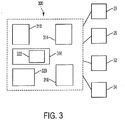
FIG. 3 is a block diagram of a crane control system according to an embodiment; -
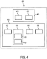
FIG. 4 is a block diagram of an optical detection system according to an embodiment; -
FIG. 5 is an example of an image captured by the optical detection system; -
FIG. 6 is another example of an image captured by the optical detection system; -
FIG. 7 is a front view of a hoist having a rope in a condition according to an embodiment; -
FIG. 8 is a front view of a hoist according to another embodiment; -
FIG. 9 is a cross-section of a hoist having a rope in another condition according to an embodiment; -
FIG. 10 is a cross-section of a hoist having a rope in another condition according to an embodiment; -
FIG. 11 is an example of a captured image of a rope wound on a hoist in another condition; -
FIG. 12 is a front view of a hoist having a rope in another condition according to an embodiment; -
FIG. 13 is a front view of a hoist having a rope in another condition according to an embodiment; -
FIG. 14 is a front view of a hoist having a rope in another condition according to an embodiment; -
FIG. 15 is a cross-section of a hoist having a rope in another condition according to an embodiment; -
FIG. 16 is a cross-section of a hoist having a rope in another condition according to an embodiment; -
FIGS. 17a-17d illustrate some examples of rope, strand and wire conditions that may be detected by the optical detection system, according to an embodiment; and -
FIG. 18 is a block diagram illustrating a method of determining a condition of a crane component, according to an embodiment. -
FIG. 1 is a side view of acrane 10 according to an embodiment described herein andFIG. 2 is a top view of thecrane 10 inFIG. 1 . Referring toFIGS. 1 and 2 , thecrane 10 may be a mobile crane, such as, but not limited to, a rough terrain crane, an all terrain crane, a truck mounted crane or an industrial crane. Thecrane 10 generally includes a carrier, or lower works, 12 and a superstructure, or upper works, 14. In one embodiment, thecarrier 12 may include various crane components, for example, aframe 16, a plurality ofground engaging elements 18 such as tires, and a suspension (not shown) interconnected between theframe 16 and theground engaging elements 18. Thecarrier 12 may also include other crane components such as one ormore outrigger assemblies 20. In one embodiment, eachoutrigger assembly 20 includes ajack 22 that is movable generally in a vertical direction to engage and disengage the ground or other support surface. Eachoutrigger assembly 20 may also include anarm 24 that is movable generally in a horizontal direction to extend toward and away from theframe 16. In one embodiment, thearm 24 is a telescoping arm having a fixed section, such as an outrigger box, and one or more telescoping sections movable relative to the fixed section. Eachjack 22 may be mounted to arespective arm 24. - The
superstructure 14 is coupled to thecarrier 12, whereby the superstructure includes aboom 32. The crane further comprises a hoist 34 coupled to thesuperstructure 14, the hoist having a hoistdrum 46 and arope 36 configured to be wound and unwound around the hoistdrum 46. In one embodiment, thesuperstructure 14 is rotatably coupled to thecarrier 12 and is configured to rotate relative to thecarrier 12 about a vertical axis 'A'. In one embodiment, thesuperstructure 14 may also include crane components, for example, a rotatingbed 26, anoperator cab 28, a counterweight assembly 30 (seeFIGS. 5-17 ) and ahook block 37 connected to therope 36. It is understood that the rope referred to herein includes metal cables, synthetic ropes, cords and other flexible members suitable for winding and unwinding on a hoist and for use with lifting equipment, such as thecrane 10 described herein. - In one embodiment, the
boom 32 may be a telescoping boom, such as a hydraulic telescoping boom. Theboom 32 may include abase section 38 and one or more nested,telescoping sections 40 configured for telescoping extension and retraction relative to thebase section 38. The one oremore telescoping sections 40 may be driven, for example, by a linear actuator (not shown). Therope 36 may extend from the hoist 34 generally along theboom 32, and extend from aboom tip 33. Thehook block 37 is connected to therope 36 at a distal end of therope 36, opposite to the hoist 34. - It is understood that present disclosure is not limited to mobile cranes of the type described above. For example, the
crane 10 may be a crawler crane, a tower crane or other lifting device using a hoist having a rope wound thereon. For example, in a tower crane, the lower works, or carrier may be in the form of a tower, and the upper works, or superstructure, may be coupled to the top of the tower. The boom may be formed as a jib on the superstructure. The hoist may be secured to the superstructure and the rope may extend along the jib. In some tower cranes, the rope may be connected to a trolley movable along the jib. It is also understood that although the hoist 34 is referred to herein in the singular, the present disclosure is not limited to cranes having only a single hoist. For example, dual hoist and continuous rope systems are envisioned as well. - Referring to
FIG. 3 , thecrane 10 may also include acrane control system 300. The CCS may include one ormore input devices 310, such as an operating knob, lever, switch, touch screen input, and the like, configured to receive an input from an operator. Theinput device 310 is operably connected to an actuator (not shown) configured to control movement of a crane component in response to an input received at theinput device 310. For example, theinput device 310 may receive an input to control slewing movement of theboom 32 androtating bed 26, lifting (luffing) movement of theboom 32, telescoping movement (extension / retraction) of theboom 32, winding or winding of therope 36 on the hoist 34, or movement of anoutrigger assembly 20. In response to receiving the input, the actuator (not shown) may be actuated to control movement of theboom 32, hoist 34,outrigger 20 or other crane component in the desired manner. The actuator may be, for example, a linear actuator, rotary actuator, drive motor and other suitable actuators known to those having skill in the art. - In one embodiment, the
crane control system 300 may include acomputer processor 314, computerreadable storage medium 316, auser interface 318 which may include the one ormore input devices 310, and acommunications interface 320. Thecrane control system 300 may be located in thecab 28 or remote from thecab 28. In some embodiments, components of thecrane control system 300 may be distributed in different sections of thecrane 10 or on devices remote from thecrane 10. The computerreadable storage medium 316 is operably coupled to thecomputer processor 314 such that it is able to communicate with thecomputer processor 314. The computerreadable storage medium 316stores instructions 322 that, when executed by thecomputer processor 314, cause thecomputer processor 314 to generate one or more signals to implement, or perform, functions. The computerreadable storage medium 316 may also store information related to the operation of thecrane 10. Theuser interface 318 is operably coupled to thecomputer processor 314 such that an operator is able to interact withcomputer processor 314. For example, through theuser interface 318 the operator may obtain information related to thecrane 10 operation and cause thecomputer processor 314 to generate one or more signals to implement a function. The operator may also input information to theuser interface 314 or the one ormore input devices 310 to cause thecomputer processor 314 to generate and transmit a control signal, via thecommunications interface 320, to the one or more of the actuators (not shown) to control or prevent movement of a crane component. In one embodiment, theinstructions 322 stored at the computerreadable storage medium 316 may be executed by thecomputer processor 314 in response to receipt of the input information from theuser interface 318 such that a function is implemented by thecomputer processor 314 to transform the input information into the control signal. - Referring to
FIG. 4 , thecrane 10 also includes anoptical detection system 400. In one embodiment, theoptical detection system 400 includes one or moreimage capture assemblies 410 and anoptical control system 402 operably and communicably connected to the one or moreimage capture assemblies 410. Theoptical control system 402 includes acomputer processor 412, a computerreadable storage medium 414 and acommunications interface 416, similar to those described above with respect to thecrane control system 300. Theoptical control system 402 optionally includes auser interface 418, as well. The computerreadable storage medium 414stores instructions 420 that, when executed by thecomputer processor 412, cause thecomputer processor 412 to generate one or more signals to implement one or more functions. Alternatively, or in addition, theoptical detection system 400 may be operably and communicably coupled to thecrane control system 300, such that theoptical detection system 400 and thecrane control system 300 share one or more of a common computer processor, computer readable storage medium, user interface, and communications interface. In one embodiment, theoptical control system 402 and thecrane control system 300 may be one and the same. In one embodiment, components of theoptical detection system 400 may be co-located with individualimage capture assemblies 410, be located in a centralized location and communicably connected to theimage capture assemblies 410 over a conventional communication interface, or be distributed among both. - Although certain processes, methods, analyses, calculations and/or determinations described herein may be referred as being carried out at one of the
crane control system 300 or the optical detection system 400 (including the optical control system 402), it is understood that the present embodiments are not limited to these configurations. That is, the processes, methods, analyses, calculations and/or determinations described herein may, in some embodiments, be carried out interchangeably between, i.e., by either one of or both, thecrane control system 300 and theoptical detection system 400, even if a particular process, method, analysis, calculation or determination is not expressly described as such herein. Similarly, it is also understood that information, such as component specifications, sensor data and the like may be interchangeably input into either thecrane control system 300 or theoptical detection system 400. - For the purposes of consistency and understanding, the various methods, processes, analyses, calculations or determinations, as well as the input of various data or information, may be described herein as being carried out by, or input to, the
optical detection system 400 oroptical control system 402. However, as detailed above, theoptical control system 400 and thecrane control system 300 may share resources or components, operate interchangeably, or be one and the same. Accordingly, it is understood that the description herein of the methods, processes, analyses, calculations, determinations, including the input of data or information, being carried out by or input into theoptical detection system 400 oroptical control system 402, includes such processes, methods, analyses, calculations, determinations, or input of data or information, being carried out by or input to, thecrane control system 300 as well. - In one embodiment, the one or more
image capture assemblies 410 may be mounted, for example, on thesuperstructure 14, thecarrier 12, or both. Suitable locations on thesuperstructure 14 for mounting the one or moreimage capture assemblies 410 include, but are not limited to, the rotatingcab 26, thecab 28, theboom 32, thecounterweight 30, or other intermediate or connecting structures between these components. Eachimage capture assembly 410 may include one or moreimage capture devices 422 configured for capturing an image across a desired field of view. In one embodiment, animage capture device 422 may be a camera, such as a digital camera, video camera, and/or a stereo camera, a LiDAR sensor, a visible light camera, an ultraviolet (UV) camera, an infrared (IR) camera, and other suitable devices capable of capturing an image for object recognition. For example, in one embodiment, theimage capture assembly 410 may be a single camera, such as a wide angle camera, or alternatively, a combination of cameras working in conjunction with one another to capture an image or images across the field of view. - The
optical detection system 400 is configured to capture an image of one or more crane components, detect one or more crane components or other objects captured in the image, analyze the detected objects and determine a status or condition of the crane component, a crane system, a crane or a series of cranes based on the captured image. Thecrane control system 300 may then alert the operator other personnel to the determined status or condition and carry out crane control functions in response to the determined status. The alert may be provided, for example, as an audio, visual, or tactile (including vibratory) signal or alarm to the operator. Alternatively, or in addition, to carry out crane control functions, thecrane control system 300 may generate a control signal to control an actuator, and in turn, movement of a desired crane components, based on the determined status or condition. - The status or condition could be, for example, an absolute position, a relative position, movement, existence, speed, acceleration, dimensions, and length of extension or retraction of a crane component. Other statuses include, for example, the type of component and a physical configuration of the component. Further, the status could be a service condition of the crane component, which may include, for example, indications of wear, damage or need for maintenance, repair or replacement of the component. It is understood that these examples are not exhaustive and the determination of other conditions are envisioned.
- The
optical detection system 400 may detect a crane component, and in some embodiments, determine a status of the crane component, using one or more detection methods, including but not limited to, one or more object recognition techniques. In some embodiments, theoptical detection system 400 may analyze an image captured by theimage capture assembly 410 to optically detect a crane component using optical recognition algorithms such as edge detection using brightness discontinuities. The optical recognition algorithms may be stored in thememory 414 and/or executed by thecomputer processor 412 at, for example, theoptical control system 402 of theoptical detection system 400. Theoptical detection system 400 may detect an edge or an end of a crane component using the above-noted edge detection and then, to determine a status, look up a position of the component based on the pixel location of the detected edge or end of the component. For example, in a field of view captured in an image, theoptical control system 402 may be calibrated to assign a position or distance to one or more pixels in the captured image. Pixels associated with the detected edge or end of the crane component may then be compared to the positions or distances assigned to those pixels to determine a position or distance of the detected edge or end of the component. - Alternatively, or in addition, the computer
readable storage medium 414 may have stored therein a plurality of baseline images. The baseline images may be captured in the same field of view as the captured image from theimage capture assembly 400. The captured image may then be compared to the stored image, for example, to detect the presence or absence of a particular component. Crane components may also be detected in manner described above. Theoptical detection system 400 may then analyze the captured image, for example, by comparing relative positions of components in the captured image and the baseline image or comparing relative conditions or appearances of the components in the captured image and the baseline image. Theoptical detection system 400 may then determine a status or condition of the detected component based on the comparison. In such an embodiment, theimage capture assembly 410 may be positioned to capture images of the object at views which closely correspond to the views at which the stored images were taken. Accordingly, accurate comparisons may be made between stored images or diagrams and captured images. - In other embodiments, the location of the end or an edge of the crane component may be calculated in real time based on the detected pixel location in the field of view of the
image capture assembly 410. For example, if the end or edge of the crane component is determined to be at a particular angle relative to a centerline of theimage capture assembly 410, then a table may give an extension corresponding to that particular angle. In other embodiments, the detected end or edge may be at a particular pixel location, which is then looked up on the chart to give an extension corresponding to that particular pixel location. In still other embodiments, once the relative location of the crane component end or edge is detected, the physical length of the crane component may be calculated using commonly known techniques such as trigonometry or geometry. - Alternatively, or in addition, the
optical detection system 400 may detect a visible target or marker 42 (seeFIGS. 5 and 6 ) disposed on the crane component. Through such detection, theoptical detection system 400 may analyze themarker 42 to determine a status of the crane component, for example, a position of the crane component, movement of the crane component, and/or the existence of the crane component. In one embodiment, themarker 42 may be horizontal lines, but other patterns may be used as well. In other embodiments, themarker 42 may be a color coating on a crane component. Theoptical detection system 400 may detect themarkers 42 using conventional pattern recognition algorithms. The pattern recognition algorithms may be stored in a memory and/or executed by a processor of theoptical control system 402 of theoptical detection system 400, and/or at the individualimage capture assemblies 410. In one embodiment, a plurality of known markers may be stored in the computerreadable storage medium 414, and amarker 42 captured in an image may be compared to the known markers. If the detectedmarker 42 is found to match a known marker, theoptical detection system 400 may then identify the detected marker as corresponding to the known marker. - The
optical detection system 400 may have stored therein, for example at the computerreadable storage medium 414,additional information 424 associated with the known marker. Accordingly, when analyzing a detectedmarker 42, theoptical detection system 400 may identify the detectedmarker 42 as corresponding to a known marker, retrieve theadditional information 424 associated with the known marker, and associate the retrieved additional information with the detectedmarker 42. Theadditional information 424 may include, for example, position information or component-specific information, such as a type of component. Conversely, theoptical detection system 400 may detect the absence of amarker 42 that was previously detected or expected to be detected, and determine a status based on the detected absence of themarker 42. - In each of these embodiments, when detecting objects in the captured image, the
optical detection system 400 is configured to differentiate the crane component ormarker 42 from the background in the image. In some embodiments, the target ormarker 42 on the crane component may be a section that is coated with a special color and/or pattern to help differentiate the crane component from the background. For example, the crane component could have a fluorescent marker, a reflective marker, or other highly visible marker to increase contrast of the crane component relative to the background. - In one embodiment, a visible portion of the
marker 42 may be captured in an image by the one or moreimage capture assemblies 410. Theoptical control system 402 may then convert the capturedmarker image 42 into a code representing the visible portion of the image. For example, if themarker 42 included five lines that were visible to and captured by theimage capture assembly 410, theoptical control system 402 may convert the image (i.e., the captured image of the marker 42) into a numeric code of five. The pattern may directly correspond to a measurement, e.g., each line could be one foot apart, or other predetermined unit of measurement, such that the numeric code is a direct measurement. In some embodiments, the numeric code may be compared to a stored table to look up information associated with themarker 42. In another embodiment, themarker 42 may be disposed at a location on the crane component that corresponds to qualitative or quantitative positions of the crane component. For example, when amarker 42 is moved into the field of view of theimage capture assembly 410, themarker 42 may be detected by theoptical detection system 400 and identified, for example, by a comparison to the stored markers as detailed above. Theoptical control system 402 may then identify and retrieve anyadditional information 424 that may be associated with the knownmarker 42 and associate the additional information with the detectedmarker 42. - Each of the aforementioned detection methods may be combined with other methods listed so as to aid, backup and/or give an alternate or redundant method of determining a status of the crane component. For example, the
marker 42 may generally be used for measurements while end or edge detection of the crane component may be used to verify the measurement. In one embodiment, it is envisioned that if themarker 42 were obscured and theimage capture assembly 410 missed a portion of themarker 42, the detected edge or end of the crane component may give a reading inconsistent with the captured, or detected,marker 42, and may alert the operator to a possible problem. - Thus, in one embodiment, the
optical detection system 400, and in particular, theoptical control system 402, may detect various objects, such as a crane component and/or themarker 42 in a captured image using object recognition software, analyze the detected objects, and determine the status of the crane or a crane component based on the detected objects. The crane component for which a status is determined may be the detected crane component or a separate crane component. The object recognition software may be stored in the computer-readable storage medium 414. In one embodiment, the object recognition software is conventional, using conventional methods understood by those having ordinary skill in the art to detect or differentiate objects in a captured image or video. It is understood that the present disclosure is not limited to the object recognition techniques described herein, and that other known object recognition techniques or algorithms may be used. -
FIGS. 5 and 6 are examples ofimages 44 captured by animage capture assembly 410. Referring toFIGS. 5 and 6 , in one embodiment, crane components in a field of view of theimage capture assembly 410 may include the hoist 34 and therope 36. Theimage capture assembly 410 may be mounted on, for example, theoperator cab 28, theboom 32, thecounterweight assembly 30 or other component of thesuperstructure 14, and be directed so that the hoist 34 is in the field of view. In one embodiment, theimage capture assembly 410 and hoist 34 remain in a fixed position relative to one another during a monitoring operation of the hoist 34 andrope 36. - The hoist 34 generally includes a rotatable hoist drum 46 (see
FIGS. 7-10 and12-16 , for example) configured to have therope 36 wound and unwound therefrom. The hoistdrum 46 may be driven to rotate by a motor (not shown). One ormore markers 42 may be disposed along a portion of the hoistdrum 46. In one embodiment, themarkers 42 may be disposed along an outer circumferential surface hoistdrum 46. Themarkers 42 may also be equally spaced from one another. - The
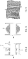
rope 36, as detailed above, may be any type of rope or cable suitable for use in lifting operations carried out by a crane. As shown, for example, inFIG. 18c , in one embodiment, therope 36 is made of a plurality ofwires 48 of material. A first plurality ofwires 48 may be wound to form afirst strand 50 of the material. In one embodiment, therope 36 may include a plurality ofstrands 50 of material wound with one another. That is, for example, a second plurality ofwires 48 may be wound to form asecond strand 50 of the material, and the first andsecond strands 50 may be wound together to form therope 36. Third, and subsequent pluralities ofwound wire 48 andstrands 50 of the material are envisioned as well. In one embodiment, therope 36 may be a DYFORM ® rope. - The
image capture assembly 410 is positioned with the hoist 34 andrope 36 in its field of view to monitor the hoist 34 andrope 36. Theimage capture assembly 410 may capture images of the hoist 34 andrope 36 at predetermined time intervals, in response to an operator input to control the hoist 34, and/or during one or more predetermined operations of the hoist 34 andrope 36. In one embodiment, theimage capture assembly 410 may also capture a video of the hoist 34 andrope 36. - In one embodiment, the
optical detection system 400 may use one or more of the object detection techniques described above to detect, for example, one or more of the hoist 34, the hoistdrum 46, therope 36, one or more wraps 52 (seeFIG. 7 ) of therope 36 on the hoistdrum 46,individual wires 50 of therope 36,individual strands 52 of therope 36, andmarkers 42 on the hoist 34. In addition, by detecting awrap 52 of therope 36, theoptical detection system 400 may also detect a number ofwraps 52 of therope 36 on the hoistdrum 46, an angle of thewraps 52 of therope 36 on the hoistdrum 46, a spacing of thewraps 52 on the hoistdrum 46, a number of layers ofrope 36 on the hoist drum 46 (see, for example, RL1, RL2, RL3 inFIGS. 15 and 16 ) and a linearity or parallelness of thewraps 52 of therope 36 on the hoistdrum 46. - In one embodiment, using the optical detection techniques described above, the
optical control system 402 may detect edges of individual rope wraps 52 on the hoistdrum 46. Examples of such detected edges are shown inFIG. 6 as E1 and E2. Similarly, theoptical control system 402 may also detect edges of thewires 48 andstrands 50. Accordingly, theoptical control system 402 may detect, qualitatively, a width of arope wrap 52,wire 48 andstrand 50. Further analysis by theoptical control system 402 of the detected objects may be performed to determine a width of arope wrap 52,wire 48 andstrand 50. Theoptical control system 402 may also detect, or be provided with, a baseline width Wrb for arope wrap 52, wire orstrand 50. The baseline width Wrb may be input to theoptical control system 402 by an operator, or identified in a captured image, for example, before operation of the hoist 34. The baseline width Wrb may correspond to a width of therope 36,wire 48 orstrand 50 in a confirmed condition, e.g., in a condition suitable for lifting operations. Examples of a baseline width Wrb and a detected with Wrd are shown inFIGS. 17a and 17d . In one embodiment, therope 36 or wraps 52 of therope 36 may detected using the methods described above. That is, a change in a condition of therope 36 may be determined based on a detected change in width ordiameter rope 36. - By way of optical detection of the components described above, the
optical control system 402 may determine one or more of the following statuses or conditions: amount ofrope 36 payed out, or unwound, from the hoistdrum 46; hook (or hook block) height; anti-two block; hoist direction; hoist erratic winding; current layer and/or last layer of therope 36 on the hoistdrum 46; third wrap of therope 36 on the hoistdrum 46; hoist speed of winding and/or unwinding; hoist movement;rope 36 size;rope 36 pull through, diving and/or bury;rope 36 climbing on the hoistdrum 46;rope 36 wrap tightness on the hoistdrum 46; reverse wrapping of therope 36;rope 36 type, including lay type; loss of tension in therope 36; andrope 36 damage, wear or other rope conditions, such as birdcaging. - With reference to
FIG. 7 , theoptical control system 402 may determine the amount ofrope 36 payed out by detecting individual wraps 52 ofrope 36 on the hoistdrum 46 in one or more captured images. Theoptical control system 402 may further analyze the captured image to count a number of thewraps 52 ofrope 36 on the hoistdrum 46. In addition, known information may be input into theoptical detection system 400. Such known information may include an initial amount, or length, ofrope 36 on hoistdrum 46 before anyrope 36 is payed out. Other known information may include an average length ofrope 36 corresponding to each wrap 52 of therope 36 on the hoistdrum 46. The average length ofrope 36 may generally correspond to a known circumference of the hoistdrum 46, but may be adjusted to account for layering of therope 36 on the hoistdrum 46. Alternatively, a length ofrope 36 for eachwrap 52 may be used which corresponds to a respective layer of therope 36 on the hoistdrum 46. For example, awrap 52 ofrope 36 on an outer layer may have a greater length associated with eachwrap 52 than awrap 52 ofrope 36 on an inner layer. In one embodiment, length of therope wrap 52 may be input for each layer (e.g., RL1, RL2...) ofrope 36 on the hoistdrum 46. Further, in one embodiment, the layers could be input into thecrane control system 300 or optical detection system400 as feedback to control the rope payout speed. Accordingly, theoptical control system 402 may detect and count a number ofwraps 52 of therope 36 on hoistdrum 46, monitor a change in the number ofwraps 52 by analyzing subsequent captured images, and count the change in the number wraps. With the calculated change in the number ofwraps 52, along with the known information, theoptical control system 402 may determine the amount ofrope 36 payed out from the hoistdrum 46. - The
optical control system 402 may determine the hook height, i.e., a height of thehook block 37, which is configured for engaging a load at a free end of therope 36, based, at least in part, on the determination of howmuch rope 36 has been payed out, described above. Calibration of the hook height may be carried out by the operator, through a controller, or automatically. For example, the operator may control the hoist 34 to raise thehook block 37 to a predetermined limit near aboom tip 33. A known boom length, location of the hoist 34 or hoists, reevings and a known boom lift angle may be input to theoptical control system 402 manually or by way of corresponding sensors (not shown) communicably connected to theoptical control system 402. With the known information and thehook block 37 positioned at the predetermined limit, the hook height at the predetermined limit position may be determined and used as a baseline value. The amount ofrope 36 subsequently payed out, which may be determined as detailed above, then corresponds to a change in the hook height. Accordingly, in one embodiment, theoptical control system 402 can determine hook height based on, for example, the baseline value of the determined amount ofrope 36 payed out. In another embodiment, the hook height may be determined by lowering the hook block to the ground to set a length. Still another embodiment may include calculating the lowest height of the hook block before a given configuration and comparing a calculated rope pay out to the calculated lowest height. - The
optical control system 402 may determine a current or approaching two-blocking condition (i.e., where a hook block is brought into contact pulley block or other component at the boom tip). Thus, theoptical control system 402 may provide anti-two-block functionality. For example, theoptical control system 402 may determine the hook height in the manner detailed above. In addition, the baseline value of the hook height is known as detailed above, and the baseline value corresponds to a predetermined limit position of thehook block 37 relative to theboom tip 33. Theoptical control system 402 may perform an analysis which includes comparing the current hook height to the baseline value. Accordingly, theoptical control system 402 may determine a two-blocking condition based on the comparison. For example, in one embodiment, a two-blocking condition may be determined if the current hook height is equal to or greater than the baseline value, for example, if thehook block 37 is moved to a position between the baseline value height and the boom tip. Alternatively, theoptical control system 402 may determine a two-blocking condition if the current hook height is within a predetermined threshold distance of the baseline. Thus, a two-blocking condition may be determined as thehook block 37 approaches theboom tip 33. - A set up function may also be incorporated to set an initial rope length. An input from the
crane control system 300 may also be used to obtain a number of reevings on thehook block 37. The anti-two block system employed by theoptical control system 402 as described herein may also be used in conjunction with, or as a backup for a traditional anti-two block system. A verification of the hoist limit may be made after each change ofhook block 37 or reeving of thehook block 37. - The
optical control system 402 may determine a direction of hoist movement by using one or more techniques. In one embodiment, and with reference toFIGS. 5, 6 and8 , the hoist 34 may include a plurality ofmarkers 42 on the hoistdrum 46. Themarkers 42 may be contrastingmarkers 42 spaced by a sufficient distance so that even at a high speed of rotation of the hoist 34, themarkers 42 may still be captured by theimage capture assembly 410 and detected in the captured image by theoptical control system 402. In one embodiment, capturing an image of the hoist 34 in which themarkers 42 may be detected is a function of a frame rate of theimage capture assembly 410, processing speed of theoptical control system 402 and a speed of the hoist 34. Theoptical control system 402 may analyze a series of two or more captured images and compare a position of the detectedmarkers 42 across the sequence of captured images. Accordingly, by detectingmarkers 42 on the hoist 34, theoptical control system 402 can determine a position ofmarkers 42, and in turn, if the position of themarkers 42 is changing between sequential captured images. By determining a change in position of a detectedmarker 42, theoptical detection system 402 may determine a direction of movement of the hoist 34. In one embodiment, theoptical control system 402 may identify the detected markers so that movement of the detected and identifiedmarkers 42 may be tracked across a sequence of captured images. - Alternatively, or in addition, the
optical control system 402 analysis may include a comparison of themarkers 42 detected in the captured images to stored images of known markers and obtain additional information associated with the knownmarkers 42. When a detectedmarker 42 is determined to match a known marker, the associated information may then be associated to the detectedmarker 42. The associated information may be position information. The position information may be, for example, a position of themarker 42 relative to a reference point on the hoistdrum 46, wherein the position of themarker 42 relative to the reference point remains fixed. For example, aparticular marker 42 may be positioned at a fixed angular distance from the reference point, and the reference point andmarker 42 rotate together with movement of the hoist 34. In this manner, theoptical control system 402 may determine, based on the detected marker ormarkers 42 and associated position information, if the hoist 34 is moving and the direction of the movement. Alternatively, or in addition, the additional information may include unique identification information for each detectedmarker 42. Accordingly, theoptical control system 42, may determine, based on the detected marker ormarkers 42, and the associated unique identification information, if the hoist 34 is moving and the direction of such movement. - Additionally, with spacing between
markers 42 being known or detected, and a frame rate of theimage capture assembly 410 being known, theoptical control system 402 may determine a direction of movement of the hoist 34 by comparing the position ofmarkers 42 in a sequence of captured images. - In another example, the
optical control system 402 may monitor therope 36 to determine if the hoist 34 is rotating. For example, at higher speeds, the number of rope wraps 52, detected in the manner described above, may be monitored. If a change in the number of rope wraps 52 is detected over a sequence of captured images, theoptical control system 402 may determine that the hoist 34 is rotating. At lower speeds, a direction of therope 36 movement may be detected over a sequence of captured images. That is, theoptical control system 402 may analyze a series of captured images, detect therope 36 and rope wraps 52, analyze a number of rope wraps 52 and determine whether therope 36 is being wound or unwound from the hoistdrum 46. In one embodiment, theoptical control system 402 analyzes a direction on the hoistdrum 46 in which the number of rope wraps 52 is increasing or decreasing. If a determination is made that the number of rope wraps 52 is changing, theoptical control system 402 may then determine that the hoist 34 is moving and a direction of the movement. In another embodiment, theoptical control system 402 may detect a leadingrope wrap 52 on the outermost layer of rope on the hoistdrum 46, and, over a sequence of images, detect if the leadingrope wrap 52 is moving toward or away from an edge of the hoistdrum 46. That is, theoptical control system 402 may determine a direction of hoist rotation by detecting and analyzing a direction of movement of the leadingrope wrap 52 on the outermost rope layer (e.g., RL1, R12...). - The
optical control system 402 may determine if therope 36 is being erratically wound on the hoist 34, for example, as shown inFIGS. 9-11 . For example, as detailed above, theoptical control system 402 is configured to detect therope 36 as well aswraps 52 of therope 36 on the hoistdrum 46. By detecting individual wraps 52, theoptical control system 402 may analyze the detected wraps 52 to compare thewraps 52 for parallelness. In one embodiment, the analysis may include a comparison of detected edges and/or centerlines of thewraps 52 toother wraps 52 on the hoistdrum 46 for parallelness. If thewraps 52 are determined to not be parallel, theoptical control system 402 may determine that therope 36 is being erratically wound on the hoist 34. - The
optical control system 402 may determine the current and last layer ofrope 36 on the hoistdrum 46. Referring toFIGS. 12 and13 , in one embodiment, this determination may be accomplished by detecting, with theoptical control system 402, therope 36 and/or the rope wraps 52 on the hoistdrum 46 in a captured image. Eachrope wrap 52 has a known, substantially constant width Wr which may be input into or calculated by theoptical control system 402. In addition, a length Lhd of the hoistdrum 46 may be known and input into theoptical detection system 400 or determined by theoptical control system 402.FIG. 12 shows the hoistdrum 46 having at least a first layer RL1 and a second layer RL2 ofrope 36 thereon. It is understood that only the visible portion of the first layer RL1 is depicted and labeled inFIG. 12 and that the first layer RL1 at least partially underlies the second layer RL2. Each rope layer RL1, RL2 is formed by a plurality ofwraps 52 extending across the length Lhd of the hoistdrum 46. Accordingly, an initial analysis may be carried out by theoptical control system 402 to calculate a baseline number ofwraps 52 in a complete layer RL1, RL2. With a total number ofwraps 52 determined, the current rope layer RL2 may be determined by comparing a detected number ofwraps 52 to the base line number of wraps per layer. In one embodiment, the baseline number of rope wraps 52, and in turn, layers RL1, RL2 may be determined by completely unwinding therope 36 from the hoistdrum 46, then winding therope 36 on the hoistdrum 46, and counting the number ofwraps 52 as the rope is wound on the hoistdrum 46. In still another example, a number of rope layers RL and in turn, a current rope layer RL may be determined by detecting a change, and/or counting a number of changes in rope layer height HRL or total diameter ofrope 36 on the hoistdrum 46. - In another embodiment, as a result of the perspective in a field of view of the
image capture assembly 410, rope wraps 52 in outer layers (RL2, for example) on the hoistdrum 46 will appear in the captured image having a greater width Wr than rope wraps 52 of inner layers (RL1, for example). Theoptical control system 402 may determine a captured a width of arope wrap 52 in the captured image, and compare the captured width to a stored table of widths, where each width corresponds to a rope layer (RL1, RL2...) on the hoistdrum 46. That is, the rope wraps 52 may be detected having a different width for each rope layer (RL1, RL2...) due to the perspective and relative distance from theimage capture assembly 410. A table stored in the computerreadable storage medium 414 may have a correspondence between a capturedrope 36 orrope wrap width 52 and a layer RL1, RL2 on the hoistdrum 46. In this manner, a current layer may be determined as well. A first layer, last layer and intermediate layers of rope may be determined in this manner as well. - Alternatively, or in addition, a last layer on the hoist
drum 46, as shown inFIG. 13 , for example, may be determined when theoptical control system 402 detects an exposed hoistdrum 46. The exposed hoistdrum 46 may be detected through a number of techniques. For example, the hoistdrum 46 may include one ormore markers 42 which become visible when therope 36 is unwound to an extent where the hoistdrum 46 is exposed, and analyze the detectedmarker 42. In another example, theoptical control system 402 may analyze the detected objects to differentiate between the hoistdrum 46 and therope 36 in a captured image using the object recognition algorithms described above. According to the invention, theoptical control system 402 detects a number of rope wraps 52 and, in an analysis of the detected rope wraps 52, compare the detected number of rope wraps to the calculated baseline number of rope wraps 52 in a layer. - The third wrap status refers to a condition where the are only three wraps of the rope remaining on the hoist
drum 46. This condition, as shown inFIG. 13 , for example, occurs when nearly all of therope 36 has been unwound from the hoistdrum 46. As detailed above, theoptical control system 402 may detect, in a captured image, the individual wraps 52 of therope 36 on the hoistdrum 46, and analyze the detected wraps 52 to count a number ofwraps 52 on thedrum 46. Accordingly, theoptical control system 402 may detect when there are only threewraps 52 of therope 36 remaining on the hoistdrum 46. Alternatively, or in addition, the hoistdrum 46 may include amarker 42 which becomes visible when only three wraps of therope 36 remain on the hoistdrum 46. Theoptical control system 402 may detect themarker 42, in a captured image, analyze themarker 42, and determine that only three wraps of therope 36 remain on the hoistdrum 46. Analysis of themarker 42 may include identifying themarker 42 as amarker 42 which indicates threewraps 52 of therope 36 remain on the hoistdrum 46. For example, the capturedmarker 42 may be compared to a stored marker, and if the capturedmarker 42 is the same as a stored marking, additional information associated with the stored marker may be retrieved including an indication that the capturedmarker 42 is an indicator of the third wrap status. - The
optical control system 402 may also determine the hoist speed of winding and/or unwinding. Referring again toFIG. 8 , in one embodiment, the hoist 34 may include the one ormore markers 42. Themarkers 42 may be detected in a captured image in the manner detailed above. Themarkers 42 may be, for example, either painted markers, decals or other similar types ofmarkers 42. With a known spacing betweenmarkers 42 and a known time interval, theoptical control system 402 can determine a rotational speed of the hoist 34 by counting the number ofmarkers 42 to move past a fixed reference point (not shown). The fixed reference point may be, for example, a physical object fixed relative to the hoist 34 and captured in the image, or a conceptual or virtual reference point generated by theoptical control system 402 within the field of view, such as a pixel or a line of pixels in the captured image. Alternatively, or in addition, theoptical control system 402 may determine hoist speed by analyzing a sequence of captured images to detect a rate of change of the number ofwraps 52 ofrope 36 on the hoistdrum 46. The wraps 52 ofrope 36 may be detected in the manner described above. Accordingly, with a known length of therope 36, or average length of therope 36, for eachwrap 52, the hoist 34 speed may be determined by detecting a change in the number ofwraps 52 over time. - The
optical control system 402 may also determine if the hoist is moving, i.e., winding or unwinding. With further reference toFIG. 8 , and as detailed above, theoptical control system 402 may detectmarkers 42 on the hoist 34. Themarkers 42 may be disposed on the hoistdrum 46 at a section not covered by therope 36. By analyzing a sequence of captured images and detecting themarkers 42, theoptical control system 402 may detect a change in position of themarkers 42, or a change inmarkers 42 at a fixed point in the captured image. Accordingly, theoptical control system 402 may determine if the hoist 34 is moving. Alternatively, or in addition, as detailed above, theoptical control system 402 may also detect rope wraps 52 on the hoistdrum 46 in a captured image and analyze the detected wraps 52 to count a number ofwraps 52. If a change in the number ofwraps 52 is detected, theoptical control system 402 may also determine that the hoist is moving. - The
optical control system 402 may also determine therope 36 size or width Wr(seeFIGS. 7 ,8 ,9 and12 , for example). In one embodiment, for example, therope 36 may be captured in an image and detected in the manner described above. An actual width Wactual of therope 36 may be entered into the opticalcontrol system system 402 as a known value. Theoptical control system 402 may calculate the rope width Wr from a captured image, for example, by counting a number of pixels. In one embodiment, arope 36 having a known width Wactual may be used to calibrate a width detection process of theoptical control system 402. For example, theoptical control system 402 may analyze a captured image, detect a rope, and analyze the detectedrope 36 to count a number of pixels extending across therope 36. Accordingly, rope width-per-pixel dimension may be calculated. The rope width-per-pixel may vary with each layer ofrope 36 on the hoistdrum 46 due to the perspective and distance to theimage capture assembly 410. - Alternatively, or in addition, the
optical control system 402 may count the number ofwraps 52 of therope 36 in a complete layer on the hoistdrum 46. With a length Lhd of the hoistdrum 46 known (for example, by user input), a width Wr of eachwrap 52, and thus a width or diameter of therope 36 may be determined. In one embodiment, the rope width determined by theoptical control system 402 may be compared to a user-input rope width, by theoptical control system 402, to confirm the rope width. Accordingly, theoptical control system 402 may determine a width or diameter of therope 36 and compare the determined diameter or width to an input rope width value. If the determined rope width value varies from the input value, theoptical control system 402 may further determine that therope 36 is damaged, worn, or has been otherwise affected in a manner which decreases the diameter of width. - The
optical control system 402 may also determine rope pull through, diving or bury of therope 36, as shown, for example, inFIG. 14 . In one embodiment, theoptical control system 402 may detect therope 36 and the rope wraps 52 in the manner described above. Referring toFIGS. 14 and15 , in one embodiment, theoptical control system 402 may analyze the detectedrope 36 and rope wraps 52 to further detect a parallelness of the rope wraps 52, in the manner described above. For example, an edge or center of each rope wrap 52 may be detected. A section ofrope 36 that has pulled through to another layer, shown inFIG. 14 at point 'P', will be detected as being non-parallel to adjacent rope wraps 52. For example, referring toFIG. 14 , and for clarity, an edge of a pulled-through section of therope 36 is shown as extrapolated line E1, while an edge of a properly wound section ofrope 36 is shown as extrapolated line E2. As may be seen from the extrapolated lines E1, E2, an edge of a properly wound section ofrope 36 does not extend parallel to an edge of a pulled-through section ofrope 36. In this manner, theoptical control system 402 may determine if therope 36 has pulled through, dove or buried. - A rope climbing condition on the hoist
drum 46, as shown inFIG. 16 for example, may also be determined by theoptical control system 402. In one embodiment, theoptical control system 402 may detect arope wrap 52 having a greater width than adjacent wraps 52. The detected greater width of therope wrap 52 may be due to closer proximity of a climbing rope C to theimage capture assembly 410. That is, a portion of therope 36 that is climbing on the hoistdrum 46 will be closer to theimage capture assembly 410. Thus, in a captured image, the climbing portion C of therope 36 will appear to have a greater width than adjacent, properly wound wraps 52 ofrope 36. In this manner, theoptical control system 402 may determine a condition where therope 36 is climbing. In one embodiment, the width of the rope wraps 52 may be measured in pixels, which may be counted during analysis of the detected rope wraps 52 by theoptical control system 402. In another embodiment, theoptical control system 402 may analyze the detected wraps of rope to determine an actual width in the manner described above. In another embodiment, theoptical control system 402 may detect an unexpected increase in rope layer diameter. For example, referring toFIG. 16 , theoptical control system 402 may expect the rope wraps 52 to continue in the third rope layer RL3. Accordingly, if theoptical control system 402 detects arope wrap 52 in a fourth rope layer RL4, then theoptical control system 402 may determine that a rope climbing condition exists. - The
optical control system 402 may also determine the rope wrap tightness on the hoistdrum 46. Referring again toFIG. 9 , the rope wrap tightness may be determined, for example, by detecting rope wraps 52 in a captured image, and analyzing the detected rope wraps 52 to obtain a count of the number of rope wraps 52 in a layer RL1 on the hoistdrum 46. The wrap tightness may also be determined by monitoring for spaces between the rope wraps 52. In one embodiment, space between adjacent rope wraps 52 may be detected when a width Wr of therope 36 is known, and adjacent rope wraps 52 are detected. In a tightly wrapped configuration, the distance between centers of adjacent wraps should be approximately equal to the rope width Wr, while in a loosely wrapped configuration, such a distance will exceed that rope width Wr by a predetermined threshold amount. That is, theoptical control system 402 may detect a plurality of rope wraps 52 and analyze the detected rope wraps 52 to identify edges and/or centers of the rope wraps 52 and where the rope wraps lie relative to one another. If a distance between adjacent rope wraps 52 varies from a known rope width outside of a suitable tolerance, theoptical control system 402 may determine that therope 36 is not tightly wound on the hoistdrum 46. - Alternatively, or in addition, with a known length Lhd of the hoist
drum 46, and a known rope diameter D, theoptical control system 402 may calculate a maximum number of rope wraps 52 to extend across the entire length of the hoistdrum 46. Theoptical control system 402 may determine that therope 36 is not tightly wrapped if the detected number of rope wraps 52 is less that the calculated maximum number of possible rope wraps 52. - Reverse wrapping occurs when the
rope 36 completely spools off of the hoistdrum 46 and then rewraps back on to the hoistdrum 46 in an opposition direction. The reverse wrapping condition may be determined by theoptical control system 402. For example, in one embodiment, theoptical control system 402 may detect the rope wraps 52 on the hoistdrum 46, and may analyze the detected rope wraps 402 to detect which side of the hoistdrum 46 therope 36 is wound or unwound from (i.e., from over or under the hoist drum 46). The detected hoist side of winding / unwinding may be established as the baseline, or proper, side of the hoistdrum 46 from which therope 36 is wound or unwound. Accordingly, if theoptical control system 402 detects therope 36 being wound or unwound from a side of the hoistdrum 46 that is different from the baseline side, theoptical control system 402 may determine that the reverse wrapping condition is occurring. Alternatively, or in addition, theoptical control system 402 may detect the lay of therope 36 in a captured image, and analyze the lay to detect a direction thereof. A reverse wrapping condition may be determined by theoptical control system 402 if the lay of onewrap 52 of therope 36 is detected as being different from the lay anotherwrap 52 ofrope 36. This is because the lay of therope 36 in a reverse wrapped portion would be opposite the lay of therope 36 in a properly wrapped portion. - The
rope 36 type may be determined by theoptical control system 402 as well. Theoptical control system 402 may analyze a captured image to detect, for example, thewires 48 which make up thestrands 50 of therope 36. By detectingindividual strands 50 of therope 36, further analysis by theoptical control system 402 may provide a lay and direction of thewires 48, rotation resistance, number ofstrands 50, and the like. Theoptical control system 402 may then determine the type ofrope 36. - Loss of rope tension may be determined by the
optical control system 402. Determination of the loss of rope tension may be based, at least in part, on a detected lack of parallelness of the rope wraps 52 on the hoistdrum 46, which may be detected and analyzed in the manner described above. For example, when therope 36 is insufficiently tensioned, therope 36 may not be tightly wound on to the hoistdrum 46, resulting in rope wraps 52 wound on thedrum 46 in a non-parallel relationship. Accordingly, theoptical control system 402 may determine a loss of rope tension. - The
optical control system 402 may also determine if arope 36 is worn or damaged. Theimage capture assembly 410 is configured to capture an image of therope 36 with sufficient resolution so as to permit detection of therope 36,individual strands 50 of therope 36, andindividual wires 48 of thestrands 50, as shown inFIGS. 17a-17d . Through analysis of the captured image or images, theoptical control system 402 may monitor therope 36 for wear or damage. A number of rope damage conditions may be determined by theoptical detection system 400 including, but not limited to, worn rope, normal wear, heat damage, rotational damage, birdcage, reduction in diameter, rope stretch, snagged wires, crushed rope, high stranding, rope kinks, core protrusion, strand nicking, distortion of lay, and broken wires. Other rope conditions, including those described in ISO 4309 and/or ASME B30, both of which are incorporated by reference herein, may be determined by theoptical detection system 400 as well. In such conditions, thewires 48 and/orstrands 50 may be displaced from an initial, undamaged position. For example, thewires 48 orstrands 50 may become loosely wrapped, extend in a non-parallel relationship to one another, or protrude outwardly. For example, awire 48 may protrude outwardly from thestrand 50. A width of thewires 48,strands 50 orrope 36 may also increase or decrease when damaged or worn. - The
optical control system 402 may detect one or more ofindividual wires 48,strands 50, andrope 36, as detailed above, and analyze the detected objects to determine if any of the above conditions are present. It is understood, however, theoptical detection system 400 is not limited to determining only the conditions described above. It is further understood that theoptical detection system 400 need not detect the specific conditions which may indicate rope damage, but rather, may detect that the condition of therope 36 has changed from an originally detected rope condition, for example, an initial undamaged condition. - In response to determining one or more of the conditions or statuses above, the
optical detection system 400 may generate an alert, message, alarm or the like to inform the operator of a determined condition or status. Alternatively, or in addition, theoptical detection system 400 may generate a control signal to control movement or operation of a crane component, for example, by controlling, or preventing operation of an actuator for a crane component. - In another embodiment, in response to determining one or more of the conditions or statuses above, the
optical detection system 400 may generate and transmit an instruction to thecrane control system 300. In response to receiving the instruction, thecrane control system 300 may then generate an alert, message, alarm or the like to the operator to inform the operator of the determined condition or status. Alternatively, or in addition, theoptical detection system 400 may generate and transmit a message to thecrane control system 300 with information indicating a detected condition or status. In response to receiving such a message, thecrane control system 300 may generate and transmit a control signal to control movement or operation of a crane component, for example, by controlling, or preventing operation of an actuator for a crane component. -
FIG. 18 is a block diagram showing amethod 500 of determining a condition of a crane component, according to an embodiment. The method includes capturing 510, with an image capture assembly, an image of a hoist on a crane and detecting 520, with anoptical control system 402, one or more objects in the captured image, wherein the one or more objects include: the hoist 34, a hoistdrum 46, arope 36 configured to be wound or unwound on the hoistdrum 46, and one ormore wraps 52 of therope 36 on the hoistdrum 46. The method further includes analyzing 530, with theoptical control system 402, the detected objects, and determining 540, with theoptical control system 402, a condition of a crane component based on the analysis of the detected objects. - Accordingly, in the embodiments above, an
image capture assembly 410 captures an image, or series of images, of a crane component, and theoptical control system 402 is configured to detect one or more objects in the captured images. Theoptical control system 402 is configured to detect a hoist, a hoist drum, a marker, a rope, a wrap of rope on the hoist drum, a strand of the rope and a wire of the strand. Theoptical control system 402 then analyzes the detected objects and determine a status or condition of a crane component. The crane component for which a status is determined may be the detected crane component in a captured image, or a separate crane component. In some embodiments, the operator may be alerted to the status, crane operations may be controlled or prevented, or both, in response to a determined status or condition. In addition, theoptical detection system 400 may detect a variety of different statuses or conditions. For example, with a captured image of a hoist and rope, the optical detection system may determine statuses such as: amount ofrope 36 payed out, or unwound, from the hoist drum; hook (or hook block) height; anti-two block; hoist direction; hoist erratic winding; current layer and/or last layer of the rope on the hoist drum; third wrap of the rope on the hoist drum; hoist speed of winding and/or unwinding; hoist movement; rope size; rope pull through, diving and/or bury; rope climbing on the hoist drum; rope wrap tightness on the hoist drum; reverse wrapping of the rope; rope type, including lay type; loss of tension in the rope; and rope damage, wear or other rope conditions, such as birdcaging. - In the present disclosure, the words "a" or "an" are to be taken to include both the singular and the plural. Conversely, any reference to plural items shall, where appropriate, include the singular.
- The disclosure is intended to cover by the appended claims all such modifications long as they fall within the scope of the claims.
Claims (18)
- A crane (10) comprising:a carrier (12);a superstructure (14) coupled to the carrier (12), the superstructure (14) including a boom (32);a hoist (34) coupled to the superstructure (14), the hoist (34) having a hoist drum (46) and a rope (36) configured to be wound and unwound around the hoist drum (46); andan optical detection system (400) comprising:an image capture assembly (410) comprising one or more image capture devices (422) configured to capture an image of the hoist (34); andan optical control system (402) configured to:detect one or more objects in the captured image, the one or more objects selected from: the rope (36), the hoist drum (46), one or more wraps (52) of rope (36) on the hoist drum (46) and a marker (42) on the hoist (34);analyze the one or more detected objects; anddetermine a condition of a crane component based on the analysis of the one or more detected objects,wherein a detected object of the one or more detected objects is the one or more wraps (52) of rope (36) on the hoist drum (46),wherein the one or more detected wraps (52) of rope (36) on the hoist drum (46) are analyzed to count a number of wraps (52) of rope (36) on the hoist drum (46),wherein the determined condition of the crane component is one or more of: an amount of rope (36) payed out or unwound from the hoist drum (46), a hook block (37) height, anti-two block, hoist drum direction of movement, current layer or last layer of the rope (36) on the hoist drum (46), hoist drum winding or unwinding speed, hoist drum movement, andwherein the determined condition is determined based on the number of wraps (52) of rope (36) detected on the hoist drum (46).
- The crane of claim 1, wherein the one or more image capture devices (422) include a camera.
- The crane of claim 1, wherein a detected object of the one or more detected objects further includes one or more of the rope (36), the hoist (34) and the marker (42), and wherein the determined condition of the crane component is further selected from one or more of: hoist erratic winding of the rope, rope size, rope pull through, diving or bury on the hoist drum (46), rope climbing on the hoist drum (46); rope wrap tightness on the hoist drum (46); reverse wrapping of the rope (36), rope type including lay type, loss of tension in the rope (36), and rope damage or wear.
- The crane of claim 1, wherein the rope (36) comprises a plurality of strands (50), and each strand (50) comprises a plurality of wires (48), wherein the optical control system (402) analyzes the one or more detected objects to identify edges of one or more of the rope (36), the strand (50) and the wire (48).
- The crane of claim 4, wherein the optical control system (402) further analyzes the one or more detected objects to determine parallelness of the edges of the rope (36), strand (50) or wire (48).
- The crane of claim 1, wherein the optical control system (402) analyzes the one or more detected objects to identify a number of pixels extending across a width of the one or more detected objects.
- The crane of claim 1, wherein the optical control system analyzes the one or more detected objects to identify a marker (42).
- The crane of claim 7, wherein the optical control system (402) analyzes the marker (42) to retrieve information associated with the marker (42).
- The crane of claim 1, wherein the optical detection system (400) is configured to generate a signal in response to determining a condition of the one or more detected objects.
- An optical detection system (400) for a crane (10) having a hoist (34) including a hoist drum (46) and a rope (36) configured to be wound and unwound around the hoist drum (46), the system (400) comprising:an image capture assembly (410) comprising one or more image capture devices (422) configured to capture an image of the hoist (34); andan optical control system (402) configured to:detect one or more objects in the captured image, the one or more objects selected from: the rope (36), the hoist drum (46), one or more wraps (52) of rope (36) on the hoist drum (46) and a marker (42) on the hoist (34);analyze the one or more detected objects; anddetermine a condition of a crane component based on the analysis of the one or more detected objects,wherein a detected object of the one or more detected objects is the one or more wraps (52) of rope (36) on the hoist drum (46),wherein the one or more detected wraps (52) of rope (36) on the hoist drum (46) are analyzed to count a number of wraps (52) of rope (36) on the hoist drum (46),wherein the determined condition of the crane component is one or more of: an amount of rope (36) payed out or unwound from the hoist drum (46), a hook block height, anti-two block, hoist drum direction of movement, current layer or last layer of the rope (36) on the hoist drum (46), hoist drum winding or unwinding speed, hoist drum movement, andwherein the determined condition is determined based on the number of wraps (52) of rope (36) detected on the hoist drum (46).
- The optical detection system of claim 10, wherein the optical control system (402) analyzes the one or more detected objects to detect edges and determine a parallelness of the edges of one or more of wraps (52) of the rope (36), strands (50) of the rope (36) or wires (48) of the strand (50).
- The optical detection system of claim 10, wherein the optical control system (402) analyzes the one or more detected objects to identify a number of pixels extending across a width of the one or more detected objects.
- The optical detection system of claim 10, wherein the optical control system (402) analyzes the one or more detected objects to identify a marker (42) and retrieves information associated with the marker (42).
- A method of determining a condition of a crane component comprising:capturing, with an image capture assembly (410), an image of a hoist (34) on a crane (10); detecting, with an optical control system (402), one or more objects in the captured image, wherein the one or more objects include: the hoist (34), a hoist drum (46), a rope (36)configured to be wound or unwound on the hoist drum (46), and one or more wraps (52) of the rope (36) on the hoist drum (46);analyzing, with the optical control system (402), the detected objects; anddetermining, with the optical control system (402), a condition of a crane component based on the analysis of the detected objects,wherein a detected object of the one or more detected objects is the one or more wraps (52) of rope (36) on the hoist drum (46),wherein the one or more detected wraps (52) of rope (36) on the hoist drum (46) are analyzed to count a number of wraps (52) of rope (36) on the hoist drum (46),wherein the determined condition of a crane component is one or more of: an amount of rope (36) payed out or unwound from the hoist drum (46), a hook block height, anti-two block, hoist drum direction of movement, current layer or last layer of the rope (36) on the hoist drum (46), hoist drum winding or unwinding speed, hoist drum movement, andwherein the determined condition is determined based on the number of wraps (52) of rope (36) detected on the hoist drum (46).
- The method of claim 14, wherein the detecting one or more objects further includes detecting a marker (42) on the hoist (34).
- The method claim 15, wherein the analyzing the detected objects further includes or more of: identifying edges of the rope (36), one or more strands (50) of the rope (36) and one or more wires (48) of the strand (50) and determining a parallelness of the detected edges, identifying a number of pixels extending across a width of one or more of the detected objects, identifying a direction of lay of the rope (36), and identifying the marker (42) and retrieving information associated with the marker (42).
- The method of claim 14, wherein a detected object of the one or more detected objects further includes one or more of the rope (36), the hoist (34) and the marker (42), and wherein the determined condition of the crane component is further selected from one or more of: hoist erratic winding of the rope (36), rope size, rope pull through, diving or bury on the hoist drum (46), rope climbing on the hoist drum (46); rope wrap tightness on the hoist drum (46); reverse wrapping of the rope (36), rope type including lay type, loss of tension in the rope (36), and rope damage or wear.
- The method of claim 14, wherein the method further comprises generating a signal in response to the condition of the crane component.
Applications Claiming Priority (1)
| Application Number | Priority Date | Filing Date | Title |
|---|---|---|---|
| US201662425449P | 2016-11-22 | 2016-11-22 |
Publications (2)
| Publication Number | Publication Date |
|---|---|
| EP3323765A1 EP3323765A1 (en) | 2018-05-23 |
| EP3323765B1 true EP3323765B1 (en) | 2020-12-30 |
Family
ID=60450505
Family Applications (4)
| Application Number | Title | Priority Date | Filing Date |
|---|---|---|---|
| EP17203109.8A Active EP3326958B1 (en) | 2016-11-22 | 2017-11-22 | Optical detection and analysis for boom angles on a crane |
| EP17203093.4A Active EP3323765B1 (en) | 2016-11-22 | 2017-11-22 | Optical detection and analysis of crane hoist and rope |
| EP17203102.3A Active EP3323767B1 (en) | 2016-11-22 | 2017-11-22 | Optical detection system for lift crane |
| EP17203098.3A Pending EP3323766A1 (en) | 2016-11-22 | 2017-11-22 | Optical detection and analysis of a counterweight assembly on a crane |
Family Applications Before (1)
| Application Number | Title | Priority Date | Filing Date |
|---|---|---|---|
| EP17203109.8A Active EP3326958B1 (en) | 2016-11-22 | 2017-11-22 | Optical detection and analysis for boom angles on a crane |
Family Applications After (2)
| Application Number | Title | Priority Date | Filing Date |
|---|---|---|---|
| EP17203102.3A Active EP3323767B1 (en) | 2016-11-22 | 2017-11-22 | Optical detection system for lift crane |
| EP17203098.3A Pending EP3323766A1 (en) | 2016-11-22 | 2017-11-22 | Optical detection and analysis of a counterweight assembly on a crane |
Country Status (3)
| Country | Link |
|---|---|
| US (4) | US11130658B2 (en) |
| EP (4) | EP3326958B1 (en) |
| JP (5) | JP7152145B2 (en) |
Families Citing this family (52)
| Publication number | Priority date | Publication date | Assignee | Title |
|---|---|---|---|---|
| US10822208B2 (en) * | 2014-12-23 | 2020-11-03 | Manitowoc Crane Companies, Llc | Crane 3D workspace spatial techniques for crane operation in proximity of obstacles |
| JP7180966B2 (en) | 2016-01-29 | 2022-11-30 | マニタウォック クレイン カンパニーズ, エルエルシー | visual outrigger monitoring system |
| US11130658B2 (en) | 2016-11-22 | 2021-09-28 | Manitowoc Crane Companies, Llc | Optical detection and analysis of a counterweight assembly on a crane |
| DE102017100883A1 (en) * | 2017-01-18 | 2018-07-19 | J. Schmalz Gmbh | Handling device and method for operating a handling device |
| EP3589574A1 (en) | 2017-02-28 | 2020-01-08 | J.Ray McDermott, S.A. | Offshore ship-to-ship lifting with target tracking assistance |
| DE202017104706U1 (en) * | 2017-08-07 | 2017-09-27 | Liebherr-Werk Ehingen Gmbh | crawler crane |
| EP3461783B1 (en) * | 2017-09-29 | 2019-11-13 | B&R Industrial Automation GmbH | Lifting device and method for controlling a lifting device |
| JP7087475B2 (en) * | 2018-03-09 | 2022-06-21 | 株式会社タダノ | Mobile crane with remote control terminal and remote control terminal |
| US11891284B2 (en) * | 2018-03-28 | 2024-02-06 | The Heil Co. | Camera safety system for aerial device |
| JP7172206B2 (en) * | 2018-07-10 | 2022-11-16 | 株式会社タダノ | crane |
| PL3594167T3 (en) | 2018-07-13 | 2021-12-13 | Epsilon Kran Gmbh. | Crane with imaging system |
| JP7192297B2 (en) * | 2018-08-08 | 2022-12-20 | 株式会社タダノ | Wire rope inspection equipment and crane |
| JP7192324B2 (en) * | 2018-09-06 | 2022-12-20 | 株式会社タダノ | work vehicle |
| US11906445B2 (en) * | 2018-10-10 | 2024-02-20 | Goodrich Corporation | Automated defect detection for wire rope using image processing techniques |
| CN112912332B (en) * | 2018-10-16 | 2023-08-01 | 株式会社多田野 | Crane device |
| US20200140239A1 (en) | 2018-11-07 | 2020-05-07 | Manitowoc Crane Companies, Llc | System for determining crane status using optical and/or electromagnetic sensors |
| CN109231034B (en) * | 2018-11-26 | 2020-08-25 | 中联重科股份有限公司 | Control device for automatic hoisting, positioning, unloading and returning of counter weight and crane |
| EP3921266A2 (en) * | 2019-02-05 | 2021-12-15 | J. Ray Mc Dermott, S.A. | System for determining position of objects |
| JP7173176B2 (en) * | 2019-02-14 | 2022-11-16 | 株式会社タダノ | Crane and path generation system |
| DE102019104864A1 (en) * | 2019-02-26 | 2020-08-27 | Liebherr-Werk Ehingen Gmbh | Monitoring system for crane components and methods for monitoring crane components |
| CN109761155A (en) * | 2019-03-15 | 2019-05-17 | 吴安艮 | A kind of detection system and its detection method for preventing tyre crane from tumbling |
| CN110120074B (en) * | 2019-05-10 | 2020-08-25 | 清研同创机器人(天津)有限公司 | Cable positioning method for live working robot in complex environment |
| JP7363294B2 (en) | 2019-09-30 | 2023-10-18 | 株式会社タダノ | Rope entanglement detection device |
| US20210122616A1 (en) * | 2019-10-29 | 2021-04-29 | KTM Solutions, Inc. | Smart Lift Device |
| JP6940216B2 (en) * | 2019-11-20 | 2021-09-22 | Necプラットフォームズ株式会社 | Direction detection system, construction machinery equipped with it, and direction detection program |
| US11802727B2 (en) | 2020-01-18 | 2023-10-31 | True Manufacturing Co., Inc. | Ice maker |
| US11602059B2 (en) | 2020-01-18 | 2023-03-07 | True Manufacturing Co., Inc. | Refrigeration appliance with detachable electronics module |
| US11656017B2 (en) | 2020-01-18 | 2023-05-23 | True Manufacturing Co., Inc. | Ice maker |
| US11255589B2 (en) | 2020-01-18 | 2022-02-22 | True Manufacturing Co., Inc. | Ice maker |
| US11578905B2 (en) | 2020-01-18 | 2023-02-14 | True Manufacturing Co., Inc. | Ice maker, ice dispensing assembly, and method of deploying ice maker |
| US11913699B2 (en) | 2020-01-18 | 2024-02-27 | True Manufacturing Co., Inc. | Ice maker |
| US11391500B2 (en) | 2020-01-18 | 2022-07-19 | True Manufacturing Co., Inc. | Ice maker |
| JP7259784B2 (en) * | 2020-03-04 | 2023-04-18 | トヨタ自動車株式会社 | Brushcutting system and brushcutting method |
| US11519652B2 (en) | 2020-03-18 | 2022-12-06 | True Manufacturing Co., Inc. | Ice maker |
| JP7343433B2 (en) * | 2020-03-26 | 2023-09-12 | 株式会社タダノ | Guide display system and cranes equipped with it |
| JP7460416B2 (en) * | 2020-03-27 | 2024-04-02 | 住友重機械建機クレーン株式会社 | Cranes and crane monitoring equipment |
| CN115362121A (en) * | 2020-03-27 | 2022-11-18 | 住友重机械建机起重机株式会社 | Construction machine and mobile crane |
| CA3164895A1 (en) * | 2020-05-14 | 2021-11-18 | Lior AVITAN | Systems and methods for remote control and automation of a tower crane |
| DE102020120699A1 (en) * | 2020-08-05 | 2022-02-10 | Konecranes Global Corporation | Slewing jib crane with a camera and methods for reducing load sway during crane operation |
| DE102020214291B3 (en) * | 2020-11-13 | 2022-03-17 | Tadano Faun Gmbh | Crane, in particular mobile crane |
| US11898331B2 (en) * | 2020-12-02 | 2024-02-13 | Caterpillar Sarl | System and method for detecting objects within a working area |
| KR102218697B1 (en) * | 2020-12-29 | 2021-02-22 | (주)삼정오토메이션 | Method for motion compensation of winch system for vessel |
| US11674731B2 (en) | 2021-01-13 | 2023-06-13 | True Manufacturing Co., Inc. | Ice maker |
| JP2022138304A (en) * | 2021-03-10 | 2022-09-26 | コベルコ建機株式会社 | Winch monitoring method, winch monitoring device, crane |
| KR20240007160A (en) | 2021-04-12 | 2024-01-16 | 스트럭처럴 서비시스, 인크. | Systems and methods for supporting crane operators |
| US11686519B2 (en) | 2021-07-19 | 2023-06-27 | True Manufacturing Co., Inc. | Ice maker with pulsed fill routine |
| CN113651245B (en) * | 2021-08-16 | 2023-07-21 | 合肥市春华起重机械有限公司 | Crane bearing capacity monitoring system |
| WO2023026568A1 (en) * | 2021-08-27 | 2023-03-02 | コベルコ建機株式会社 | Remote operation system and remote operation composite system |
| CN113450405B (en) * | 2021-08-31 | 2021-11-12 | 河南科技学院 | Method for positioning cylindrical part and hooking grapple of yard crane |
| WO2024015545A1 (en) * | 2022-07-14 | 2024-01-18 | Schlumberger Technology Corporation | Cable damage detection by machine vision |
| JP7347623B1 (en) | 2022-10-12 | 2023-09-20 | フジテック株式会社 | How to adjust and check the total weight of the elevator balancing weight |
| KR102578137B1 (en) * | 2023-04-06 | 2023-09-13 | 삼공 주식회사 | Double hoist crane device |
Family Cites Families (141)
| Publication number | Priority date | Publication date | Assignee | Title |
|---|---|---|---|---|
| US4216868A (en) | 1978-08-04 | 1980-08-12 | Eaton Corporation | Optical digital sensor for crane operating aid |
| US4577344A (en) | 1983-01-17 | 1986-03-18 | Automatix Incorporated | Vision system |
| FR2611826B1 (en) | 1987-02-25 | 1989-06-16 | Masseron Alain | TELESCOPIC ARM THAT CAN BE DESIGNED IN A DEMOUNTABLE FORM |
| US4826391A (en) * | 1988-02-23 | 1989-05-02 | The University Of British Columbia | Manipulator arm position sensing |
| JPH0256397A (en) | 1988-08-22 | 1990-02-26 | Toshiba Corp | Checking device for crane wore rope |
| US5182843A (en) | 1989-05-16 | 1993-02-02 | Canon Kabushiki Kaisha | Method for assembling objects by reversing up and down an attitude of the assembly |
| KR960006116B1 (en) | 1990-03-23 | 1996-05-09 | 가부시끼가이샤 고오베 세이꼬오쇼 | Method and apparatus for controlling stopping of turning of upper swing unit for construction machines, and angle of inclination computing apparatus |
| WO1991019665A1 (en) | 1990-06-15 | 1991-12-26 | Kato Works Co., Ltd. | Hook lift display apparatus of crane |
| AU637377B2 (en) | 1990-06-15 | 1993-05-27 | Kato Works Co., Ltd. | Hook lift display apparatus of crane |
| US5645181A (en) | 1992-02-12 | 1997-07-08 | Kato Works Co., Ltd. | Method for detecting a crane hook lifting distance |
| US5170681A (en) | 1992-03-20 | 1992-12-15 | Gloria Kemp | Wrench apparatus |
| US5392935A (en) | 1992-10-06 | 1995-02-28 | Obayashi Corporation | Control system for cable crane |
| CN2154484Y (en) | 1992-12-28 | 1994-01-26 | 重庆建筑工程学院 | Automatic detector for steel cable |
| DE4416707A1 (en) | 1994-05-11 | 1995-11-16 | Tax Ingenieurgesellschaft Mbh | Method for correcting the destination of a load carrier and load transport system |
| JPH08157188A (en) | 1994-12-08 | 1996-06-18 | Kobe Steel Ltd | Deflection detecting method of boom in crane and operation radius calculating method and operation radius calculating device |
| JPH08259182A (en) * | 1995-03-27 | 1996-10-08 | Tadano Ltd | Gentile stop device of crane |
| JPH08290892A (en) | 1995-04-24 | 1996-11-05 | Mitsubishi Heavy Ind Ltd | Steady brace device of suspended cargo |
| JPH08333086A (en) * | 1995-06-09 | 1996-12-17 | Komatsu Ltd | Processor of photographed picture image of hung cargo |
| US5726907A (en) | 1995-07-31 | 1998-03-10 | Southwest Research Institute | Biaxial non-contacting strain measurement using machine vision |
| US6256553B1 (en) | 1995-11-14 | 2001-07-03 | Sime Oy | Method and device to pick up, transport and put down a load |
| JP3150636B2 (en) | 1996-12-06 | 2001-03-26 | 三菱重工業株式会社 | Crane lowering collision prevention device |
| JP3254152B2 (en) | 1996-12-10 | 2002-02-04 | 三菱重工業株式会社 | Crane handling route setting method and apparatus |
| US6140930A (en) | 1997-02-27 | 2000-10-31 | Shaw; Jack B. | Crane safety devices and methods |
| US6894621B2 (en) | 1997-02-27 | 2005-05-17 | Jack B. Shaw | Crane safety devices and methods |
| US6549139B2 (en) | 1997-02-27 | 2003-04-15 | Jack B. Shaw, Jr. | Crane safety device and methods |
| US5960849A (en) | 1997-08-13 | 1999-10-05 | Gmi Holdings, Inc. | Cable slack detector |
| JP2000034093A (en) | 1998-07-21 | 2000-02-02 | Kobe Steel Ltd | Slewing type working machinery and its safety working area and setting method of rated load |
| JP2000143169A (en) * | 1998-11-13 | 2000-05-23 | Sumitomo Constr Mach Co Ltd | Hoist rope overwind prevention device for crane |
| DE19857779A1 (en) | 1998-12-04 | 2000-06-15 | Mannesmann Ag | Crane, especially mobile crane |
| US6577758B1 (en) | 1999-09-24 | 2003-06-10 | Cognex Technology And Investment Corporation | Image position detection technique in which input parameters can be easily determined |
| JP2001158599A (en) | 1999-12-02 | 2001-06-12 | Yaskawa Electric Corp | Positioning device for boom for high lift work |
| US7121012B2 (en) | 1999-12-14 | 2006-10-17 | Voecks Larry A | Apparatus and method for measuring and controlling pendulum motion |
| US6748104B1 (en) | 2000-03-24 | 2004-06-08 | Cognex Corporation | Methods and apparatus for machine vision inspection using single and multiple templates or patterns |
| JP3785061B2 (en) | 2000-10-27 | 2006-06-14 | 三菱重工業株式会社 | Container position detection method and apparatus for cargo handling crane, container landing and stacking control method |
| US6765224B1 (en) | 2000-12-29 | 2004-07-20 | Cognex Corporation | Machine vision method and system for the inspection of a material |
| US6588610B2 (en) | 2001-03-05 | 2003-07-08 | National University Of Singapore | Anti-sway control of a crane under operator's command |
| US6634112B2 (en) | 2001-03-12 | 2003-10-21 | Ensco, Inc. | Method and apparatus for track geometry measurement |
| US20030137590A1 (en) | 2002-01-18 | 2003-07-24 | Barnes Danny S. | Machine vision system with auxiliary video input |
| JP3671042B2 (en) | 2002-02-08 | 2005-07-13 | 三菱重工業株式会社 | crane |
| US7305115B2 (en) | 2002-02-22 | 2007-12-04 | Siemens Energy And Automation, Inc. | Method and system for improving ability of a machine vision system to discriminate features of a target |
| JP2004001987A (en) | 2002-03-25 | 2004-01-08 | Hitachi Constr Mach Co Ltd | Operation support device |
| US7310431B2 (en) | 2002-04-10 | 2007-12-18 | Canesta, Inc. | Optical methods for remotely measuring objects |
| US6999641B2 (en) | 2002-05-03 | 2006-02-14 | Jerry Gene Williams | Measurement of large strains in ropes using plastic optical fibers |
| US7963695B2 (en) | 2002-07-23 | 2011-06-21 | Rapiscan Systems, Inc. | Rotatable boom cargo scanning system |
| DE10245889B4 (en) | 2002-09-30 | 2008-07-31 | Siemens Ag | Method and / or device for determining a pendulum of a load of a hoist |
| DE10251910B4 (en) | 2002-11-07 | 2013-03-14 | Siemens Aktiengesellschaft | container crane |
| WO2004080882A1 (en) | 2003-03-07 | 2004-09-23 | Mhe Technologies, Inc. | Hoist apparatus rope sensing device |
| EP1652810B1 (en) | 2003-08-05 | 2012-12-19 | Sintokogio, Ltd. | Crane and controller for the same |
| US7289875B2 (en) | 2003-11-14 | 2007-10-30 | Siemens Technology-To-Business Center Llc | Systems and methods for sway control |
| JP2006056665A (en) * | 2004-08-20 | 2006-03-02 | Tadano Ltd | Over-loading prevent device of work vehicle |
| AU2004222734B1 (en) | 2004-10-20 | 2006-01-19 | Leica Geosystems Ag | Method and apparatus for monitoring a load condition of a dragline |
| JP4678233B2 (en) * | 2005-05-16 | 2011-04-27 | コベルコクレーン株式会社 | Crane and its weight detection device |
| KR101206312B1 (en) | 2005-06-28 | 2012-11-29 | 에이비비 에이비 | Load control device for a crane |
| US7599762B2 (en) | 2005-08-24 | 2009-10-06 | Rockwell Automatino Technologies, Inc. | Model-based control for crane control and underway replenishment |
| WO2007094190A1 (en) | 2006-02-15 | 2007-08-23 | Kabushiki Kaisha Yaskawa Denki | Device for preventing sway of suspended load |
| US7656459B2 (en) | 2006-04-20 | 2010-02-02 | Pacific Systems Solution Llc | Crane hook and trolley camera system |
| JP5091447B2 (en) | 2006-09-25 | 2012-12-05 | 株式会社タダノ | Peripheral monitoring support device for work equipment-equipped vehicles |
| DE102006046469A1 (en) | 2006-09-29 | 2008-04-03 | K.A. Schmersal Holding Kg | Vehicle-mounted crane, has ballasting device for receiving ballast weights, and machine readable data carrier for storing weight readings |
| SE530490C2 (en) | 2006-12-21 | 2008-06-24 | Abb Ab | Calibration device, method and system for a container crane |
| EP2149067A1 (en) | 2007-04-19 | 2010-02-03 | D.V.P. Technologies Ltd. | Imaging system and method for use in monitoring a field of regard |
| DE102007043498A1 (en) | 2007-09-12 | 2009-03-19 | Pepperl + Fuchs Gmbh | Method for positioning a vehicle and positioning systems |
| JP5243760B2 (en) | 2007-09-19 | 2013-07-24 | 株式会社タダノ | Outrigger extension amount detection device |
| WO2009047719A2 (en) | 2007-10-11 | 2009-04-16 | Herbert Schmitz | A method, apparatus and system for monitoring the winding of rope about a drum |
| US20100070179A1 (en) | 2008-09-17 | 2010-03-18 | Cameron John F | Providing an autonomous position of a point of interest to a lifting device to avoid collision |
| FR2939783B1 (en) | 2008-12-15 | 2013-02-15 | Schneider Toshiba Inverter | DEVICE FOR CONTROLLING THE DISPLACEMENT OF A LOAD SUSPENDED TO A CRANE |
| JP2010241548A (en) | 2009-04-03 | 2010-10-28 | Kansai Electric Power Co Inc:The | Safety confirmation device of crane |
| US20100277298A1 (en) | 2009-04-29 | 2010-11-04 | Delphi Technologies, Inc. | Detection system and method thereof |
| IT1394723B1 (en) | 2009-06-10 | 2012-07-13 | Rolic Invest Sarl | WIND POWER PLANT FOR THE GENERATION OF ELECTRICITY AND ITS CONTROL METHOD |
| US9278834B2 (en) | 2009-08-06 | 2016-03-08 | Manitowoc Crane Group, LLC | Lift crane with moveable counterweight |
| US8272521B1 (en) | 2009-10-05 | 2012-09-25 | Auto Crane Company | Crane moment load and load delivery system control and method |
| US8682541B2 (en) | 2010-02-01 | 2014-03-25 | Trimble Navigation Limited | Sensor unit system |
| US8768609B2 (en) | 2010-02-01 | 2014-07-01 | Trimble Navigation Limited | Sensor unit system |
| EP2383566B1 (en) * | 2010-04-28 | 2013-10-23 | Winspect GmbH | Method and system for testing ropes |
| KR20110123928A (en) | 2010-05-10 | 2011-11-16 | 한국과학기술원 | Trolley assembly for container crane |
| WO2011155749A2 (en) | 2010-06-07 | 2011-12-15 | 연세대학교 산학협력단 | Tower crane navigation system |
| EP2595911B1 (en) | 2010-07-23 | 2015-10-21 | Inventio AG | Nondestructive testing of a carrier element of a lift installation |
| EP2423149B1 (en) | 2010-08-24 | 2016-11-23 | Manitowoc Crane Group France SAS | Mounting for an auxiliary lifting device on a mobile crane |
| JP5569344B2 (en) * | 2010-11-05 | 2014-08-13 | コベルコクレーン株式会社 | Counterweight weight detection device |
| CN102607656B (en) * | 2011-01-14 | 2015-12-16 | 株式会社多田野 | Crane fuel consumption display device |
| DE202011001846U1 (en) * | 2011-01-24 | 2012-04-30 | Liebherr-Components Biberach Gmbh | Device for detecting the Ablegereife a high-strength fiber rope when used on hoists |
| CN202093395U (en) | 2011-04-06 | 2011-12-28 | 嘉兴电力局 | Earth station remote control device for unmanned vehicle |
| US9238570B2 (en) | 2011-07-05 | 2016-01-19 | Trimble Navigation Limited | Crane maneuvering assistance |
| FI20115922A0 (en) | 2011-09-20 | 2011-09-20 | Konecranes Oyj | Crane control |
| EP2573039A3 (en) * | 2011-09-23 | 2013-06-26 | Manitowoc Crane Companies, LLC | Outrigger monitoring system and methods |
| JP5870444B2 (en) * | 2011-10-12 | 2016-03-01 | 清水建設株式会社 | LOCATION DEVICE, LOCATION METHOD, LOCATION PROGRAM, AND LOCATION SYSTEM |
| US9696897B2 (en) | 2011-10-19 | 2017-07-04 | The Regents Of The University Of California | Image-based measurement tools |
| JP6017782B2 (en) | 2011-12-09 | 2016-11-02 | 株式会社タダノ | Information system for height information of objects around suspended loads |
| JP5971994B2 (en) | 2012-03-19 | 2016-08-17 | 株式会社タダノ | Crane work monitoring device |
| DE102012006494B4 (en) | 2012-03-30 | 2014-03-13 | Manitowoc Crane Group France Sas | Mobile crane with decoupling counterweight arrangement |
| CN102661952A (en) | 2012-05-02 | 2012-09-12 | 慈溪思达电子科技有限公司 | Image-based steel wire rope breakage detection device |
| US9415976B2 (en) * | 2012-05-10 | 2016-08-16 | Trimble Navigation Limited | Crane collision avoidance |
| US8659408B2 (en) | 2012-05-22 | 2014-02-25 | Delphi Technologies, Inc. | Object detection system and method using a camera and a multiple zone temperature sensor |
| FI126364B (en) | 2012-05-25 | 2016-10-31 | Konecranes Global Oy | Determining the travel distance of the hoist |
| GB201210057D0 (en) | 2012-06-07 | 2012-07-25 | Jaguar Cars | Crane and related method of operation |
| CN102756976B (en) | 2012-07-23 | 2014-07-16 | 中联重科股份有限公司 | Equipment, system and method for bending deflection detection and safety control of suspension arm, and crane |
| WO2014019132A1 (en) | 2012-07-31 | 2014-02-06 | Harman International Industries, Incorporated | System and method for detecting obstacles using a single camera |
| CN102795547B (en) | 2012-08-31 | 2014-07-16 | 中国人民解放军国防科学技术大学 | Real-time photographic measuring method of position and swing angle of lifting hook of crane |
| US9300954B2 (en) | 2012-09-21 | 2016-03-29 | Tadano Ltd. | Surrounding information-obtaining device for working vehicle |
| WO2014047840A1 (en) | 2012-09-27 | 2014-04-03 | 中联重科股份有限公司 | Crane control method, system and crane based on image processing |
| EP2722302B1 (en) | 2012-10-17 | 2017-05-24 | Iveco Magirus Ag | Utility vehicle with monitoring system for monitoring the position of the outriggers |
| NO339902B1 (en) | 2012-11-02 | 2017-02-13 | Rolls Royce Marine As | SYSTEM TO CONTROL OR LOAD A CABLE OR LIKE A DRUM |
| DE202012012116U1 (en) | 2012-12-17 | 2014-03-19 | Liebherr-Components Biberach Gmbh | Tower Crane |
| WO2014123228A1 (en) | 2013-02-08 | 2014-08-14 | 日立建機株式会社 | Surroundings monitoring device for slewing-type work machine |
| DE102013006258A1 (en) | 2013-04-11 | 2014-10-16 | Liebherr-Components Biberach Gmbh | crane |
| EP2799386B1 (en) | 2013-05-03 | 2016-11-09 | Manitowoc Crane Group France SAS | Device and method for determination and monitoring a counterweight which is fitted to a crane |
| DE102013008348B4 (en) | 2013-05-16 | 2020-01-16 | Tadano Faun Gmbh | crane |
| WO2014189009A1 (en) | 2013-05-21 | 2014-11-27 | 株式会社タダノ | Camera orientation detecting device and work region line displaying device |
| CN203319435U (en) | 2013-06-28 | 2013-12-04 | 洛阳威尔若普检测技术有限公司 | Elevator steel wire rope breakage monitoring device based on optical propagation principle |
| US9938119B2 (en) | 2013-07-26 | 2018-04-10 | Electronic Power Design, Inc. | Method and apparatus for retrofitting a pedestal crane |
| CN103398668B (en) | 2013-08-06 | 2016-08-10 | 中联重科股份有限公司 | The detection device of boom system and detection method |
| JP2015101470A (en) | 2013-11-27 | 2015-06-04 | 株式会社大林組 | Crane operation monitoring system and method |
| US9452531B2 (en) | 2014-02-04 | 2016-09-27 | Microsoft Technology Licensing, Llc | Controlling a robot in the presence of a moving object |
| US9410659B2 (en) | 2014-02-10 | 2016-08-09 | The Boeing Company | Automated mobile boom system for crawling robots |
| DE102014008094A1 (en) | 2014-06-02 | 2015-12-03 | Liebherr-Werk Nenzing Gmbh | Method for controlling the alignment of a crane load and a jib crane |
| JP6402497B2 (en) | 2014-06-06 | 2018-10-10 | 株式会社タダノ | Height detection device |
| JP6710493B2 (en) * | 2014-06-18 | 2020-06-17 | 住友建機株式会社 | Construction machinery and excavators |
| US9718650B2 (en) | 2014-07-16 | 2017-08-01 | Institute of Nuclear Energy Research, Atomic Energy Council, Executive Yuan, R.O.C. | Control device using image tracking technology for controlling overhead crane system |
| US9688518B2 (en) | 2014-07-31 | 2017-06-27 | Trimble Inc. | Three dimensional rendering of job site |
| US20160035251A1 (en) | 2014-07-31 | 2016-02-04 | Trimble Navigation Limited | Crane operator guidance |
| DE102014018063B4 (en) | 2014-12-05 | 2021-02-18 | Liebherr-Werk Ehingen Gmbh | Crane, especially crawler or mobile crane |
| US9850109B2 (en) | 2014-12-23 | 2017-12-26 | Manitowoc Crane Companies, Llc | Crane 3D workspace spatial techniques for crane operation in proximity of obstacles |
| CN104477723B (en) | 2014-12-25 | 2017-03-15 | 中国矿业大学 | A kind of mine hoist winds the determination methods of reel disorder cable monitoring system |
| CN104535356B (en) | 2015-01-19 | 2017-08-29 | 中南大学 | A kind of roller steel wire rope rope fault monitoring method and system based on machine vision |
| DE102015202734A1 (en) | 2015-02-16 | 2016-08-18 | Terex Cranes Germany Gmbh | Crane and method for influencing a deformation of a boom system of such a crane |
| JP6550803B2 (en) | 2015-03-10 | 2019-07-31 | 株式会社タダノ | Image display device |
| JP6536789B2 (en) | 2015-03-10 | 2019-07-03 | コベルコ建機株式会社 | Rope looseness detection device |
| FI20155599A (en) | 2015-08-21 | 2017-02-22 | Konecranes Global Oy | Control of a lifting device |
| WO2017067651A1 (en) | 2015-10-21 | 2017-04-27 | Liebherr-Components Biberach Gmbh | Device for detecting the replacement state of wear of a high-strength fibre cable for hoisting devices |
| JP7180966B2 (en) | 2016-01-29 | 2022-11-30 | マニタウォック クレイン カンパニーズ, エルエルシー | visual outrigger monitoring system |
| JP6097441B1 (en) | 2016-03-18 | 2017-03-15 | 株式会社タダノ | Crane work auxiliary device |
| DE202016002296U1 (en) * | 2016-04-08 | 2017-07-12 | Liebherr-Components Biberach Gmbh | Construction machinery |
| EP3408211B1 (en) | 2016-04-08 | 2022-06-08 | Liebherr-Components Biberach GmbH | Crane |
| CN105668419A (en) | 2016-04-15 | 2016-06-15 | 徐州重型机械有限公司 | Sidewise bending detection method and device for crane boom and crane |
| DE202016005619U1 (en) | 2016-09-12 | 2016-12-19 | Liebherr-Werk Ehingen Gmbh | crane |
| DE102016011354A1 (en) | 2016-09-20 | 2018-03-22 | Liebherr-Werk Biberach Gmbh | Control station for a crane, excavator and the like |
| JP6880648B2 (en) | 2016-10-21 | 2021-06-02 | 株式会社タダノ | Mobile crane |
| US11130658B2 (en) | 2016-11-22 | 2021-09-28 | Manitowoc Crane Companies, Llc | Optical detection and analysis of a counterweight assembly on a crane |
| US10721859B2 (en) * | 2017-01-08 | 2020-07-28 | Dolly Y. Wu PLLC | Monitoring and control implement for crop improvement |
| EP3351699B1 (en) | 2017-01-20 | 2020-12-09 | Hexagon Technology Center GmbH | Construction management system and method |
| SE541528C2 (en) | 2017-03-03 | 2019-10-29 | Cargotec Patenter Ab | A vehicle provided with an arrangement for determining a three dimensional representation of a movable member |
| JP6895835B2 (en) * | 2017-07-21 | 2021-06-30 | 株式会社タダノ | Guide information display device and crane |
-
2017
- 2017-11-21 US US15/819,234 patent/US11130658B2/en active Active
- 2017-11-21 US US15/819,573 patent/US10829347B2/en active Active
- 2017-11-21 US US15/819,369 patent/US11124392B2/en active Active
- 2017-11-21 US US15/819,171 patent/US10717631B2/en active Active
- 2017-11-22 EP EP17203109.8A patent/EP3326958B1/en active Active
- 2017-11-22 JP JP2017224705A patent/JP7152145B2/en active Active
- 2017-11-22 EP EP17203093.4A patent/EP3323765B1/en active Active
- 2017-11-22 EP EP17203102.3A patent/EP3323767B1/en active Active
- 2017-11-22 JP JP2017224769A patent/JP2018115077A/en active Pending
- 2017-11-22 JP JP2017224692A patent/JP7152144B2/en active Active
- 2017-11-22 EP EP17203098.3A patent/EP3323766A1/en active Pending
- 2017-11-22 JP JP2017224789A patent/JP7207848B2/en active Active
-
2022
- 2022-11-07 JP JP2022177846A patent/JP2023011875A/en active Pending
Non-Patent Citations (1)
| Title |
|---|
| None * |
Also Published As
| Publication number | Publication date |
|---|---|
| US11130658B2 (en) | 2021-09-28 |
| US20180143011A1 (en) | 2018-05-24 |
| JP2018115078A (en) | 2018-07-26 |
| US10717631B2 (en) | 2020-07-21 |
| US10829347B2 (en) | 2020-11-10 |
| US20180141788A1 (en) | 2018-05-24 |
| US20180141789A1 (en) | 2018-05-24 |
| JP2018127357A (en) | 2018-08-16 |
| EP3326958A1 (en) | 2018-05-30 |
| EP3323766A1 (en) | 2018-05-23 |
| JP7152144B2 (en) | 2022-10-12 |
| JP2018115077A (en) | 2018-07-26 |
| EP3326958B1 (en) | 2019-11-20 |
| JP2018138489A (en) | 2018-09-06 |
| EP3323767B1 (en) | 2020-12-30 |
| JP2023011875A (en) | 2023-01-24 |
| US20180141787A1 (en) | 2018-05-24 |
| EP3323765A1 (en) | 2018-05-23 |
| JP7152145B2 (en) | 2022-10-12 |
| EP3323767A1 (en) | 2018-05-23 |
| JP7207848B2 (en) | 2023-01-18 |
| US11124392B2 (en) | 2021-09-21 |
Similar Documents
| Publication | Publication Date | Title |
|---|---|---|
| EP3323765B1 (en) | Optical detection and analysis of crane hoist and rope | |
| JP7471796B2 (en) | System for determining crane status using optical and/or electromagnetic sensors - Patents.com | |
| JP6916173B2 (en) | High-strength fiber rope replacement status recognition device for lifting equipment | |
| AU2015372216B2 (en) | Disorder rope monitoring system and judging method for winding reel of mine hoist | |
| US10597266B2 (en) | Crane and method for monitoring the overload protection of such a crane | |
| US10472214B2 (en) | Crane and method for monitoring the overload protection of such a crane | |
| US10633225B2 (en) | Crane information presentation system | |
| JP7192297B2 (en) | Wire rope inspection equipment and crane | |
| CN113247812A (en) | Wire rope reel rope disorder fault early warning device using infrared distance measurement technology | |
| CN112811335A (en) | Cable arrangement mechanism, winding device, operation machine and cable arrangement control method | |
| US20230312312A1 (en) | Winch drum monitoring device | |
| KR20190087758A (en) | Crane | |
| US11772943B2 (en) | Monitoring device for winch drum | |
| US20230406678A1 (en) | Estimation apparatus and crane | |
| JP2023147859A (en) | Monitoring device of winch drum and winch drum | |
| JP2020079128A (en) | Overwinding prevention device | |
| KR20200099298A (en) | Crane blackbox system |
Legal Events
| Date | Code | Title | Description |
|---|---|---|---|
| PUAI | Public reference made under article 153(3) epc to a published international application that has entered the european phase |
Free format text: ORIGINAL CODE: 0009012 |
|
| STAA | Information on the status of an ep patent application or granted ep patent |
Free format text: STATUS: THE APPLICATION HAS BEEN PUBLISHED |
|
| AK | Designated contracting states |
Kind code of ref document: A1 Designated state(s): AL AT BE BG CH CY CZ DE DK EE ES FI FR GB GR HR HU IE IS IT LI LT LU LV MC MK MT NL NO PL PT RO RS SE SI SK SM TR |
|
| AX | Request for extension of the european patent |
Extension state: BA ME |
|
| STAA | Information on the status of an ep patent application or granted ep patent |
Free format text: STATUS: REQUEST FOR EXAMINATION WAS MADE |
|
| 17P | Request for examination filed |
Effective date: 20181121 |
|
| RBV | Designated contracting states (corrected) |
Designated state(s): AL AT BE BG CH CY CZ DE DK EE ES FI FR GB GR HR HU IE IS IT LI LT LU LV MC MK MT NL NO PL PT RO RS SE SI SK SM TR |
|
| GRAP | Despatch of communication of intention to grant a patent |
Free format text: ORIGINAL CODE: EPIDOSNIGR1 |
|
| STAA | Information on the status of an ep patent application or granted ep patent |
Free format text: STATUS: GRANT OF PATENT IS INTENDED |
|
| RIC1 | Information provided on ipc code assigned before grant |
Ipc: B66C 23/36 20060101ALI20200518BHEP Ipc: B66C 23/76 20060101ALI20200518BHEP Ipc: B66C 13/46 20060101AFI20200518BHEP Ipc: B66C 15/06 20060101ALI20200518BHEP |
|
| INTG | Intention to grant announced |
Effective date: 20200619 |
|
| GRAS | Grant fee paid |
Free format text: ORIGINAL CODE: EPIDOSNIGR3 |
|
| GRAA | (expected) grant |
Free format text: ORIGINAL CODE: 0009210 |
|
| STAA | Information on the status of an ep patent application or granted ep patent |
Free format text: STATUS: THE PATENT HAS BEEN GRANTED |
|
| AK | Designated contracting states |
Kind code of ref document: B1 Designated state(s): AL AT BE BG CH CY CZ DE DK EE ES FI FR GB GR HR HU IE IS IT LI LT LU LV MC MK MT NL NO PL PT RO RS SE SI SK SM TR |
|
| REG | Reference to a national code |
Ref country code: GB Ref legal event code: FG4D |
|
| REG | Reference to a national code |
Ref country code: DE Ref legal event code: R096 Ref document number: 602017030386 Country of ref document: DE |
|
| REG | Reference to a national code |
Ref country code: AT Ref legal event code: REF Ref document number: 1349755 Country of ref document: AT Kind code of ref document: T Effective date: 20210115 |
|
| REG | Reference to a national code |
Ref country code: IE Ref legal event code: FG4D |
|
| PG25 | Lapsed in a contracting state [announced via postgrant information from national office to epo] |
Ref country code: RS Free format text: LAPSE BECAUSE OF FAILURE TO SUBMIT A TRANSLATION OF THE DESCRIPTION OR TO PAY THE FEE WITHIN THE PRESCRIBED TIME-LIMIT Effective date: 20201230 Ref country code: NO Free format text: LAPSE BECAUSE OF FAILURE TO SUBMIT A TRANSLATION OF THE DESCRIPTION OR TO PAY THE FEE WITHIN THE PRESCRIBED TIME-LIMIT Effective date: 20210330 Ref country code: FI Free format text: LAPSE BECAUSE OF FAILURE TO SUBMIT A TRANSLATION OF THE DESCRIPTION OR TO PAY THE FEE WITHIN THE PRESCRIBED TIME-LIMIT Effective date: 20201230 Ref country code: GR Free format text: LAPSE BECAUSE OF FAILURE TO SUBMIT A TRANSLATION OF THE DESCRIPTION OR TO PAY THE FEE WITHIN THE PRESCRIBED TIME-LIMIT Effective date: 20210331 |
|
| REG | Reference to a national code |
Ref country code: AT Ref legal event code: MK05 Ref document number: 1349755 Country of ref document: AT Kind code of ref document: T Effective date: 20201230 |
|
| PG25 | Lapsed in a contracting state [announced via postgrant information from national office to epo] |
Ref country code: SE Free format text: LAPSE BECAUSE OF FAILURE TO SUBMIT A TRANSLATION OF THE DESCRIPTION OR TO PAY THE FEE WITHIN THE PRESCRIBED TIME-LIMIT Effective date: 20201230 Ref country code: BG Free format text: LAPSE BECAUSE OF FAILURE TO SUBMIT A TRANSLATION OF THE DESCRIPTION OR TO PAY THE FEE WITHIN THE PRESCRIBED TIME-LIMIT Effective date: 20210330 Ref country code: LV Free format text: LAPSE BECAUSE OF FAILURE TO SUBMIT A TRANSLATION OF THE DESCRIPTION OR TO PAY THE FEE WITHIN THE PRESCRIBED TIME-LIMIT Effective date: 20201230 |
|
| REG | Reference to a national code |
Ref country code: NL Ref legal event code: MP Effective date: 20201230 |
|
| PG25 | Lapsed in a contracting state [announced via postgrant information from national office to epo] |
Ref country code: HR Free format text: LAPSE BECAUSE OF FAILURE TO SUBMIT A TRANSLATION OF THE DESCRIPTION OR TO PAY THE FEE WITHIN THE PRESCRIBED TIME-LIMIT Effective date: 20201230 |
|
| REG | Reference to a national code |
Ref country code: LT Ref legal event code: MG9D |
|
| PG25 | Lapsed in a contracting state [announced via postgrant information from national office to epo] |
Ref country code: PT Free format text: LAPSE BECAUSE OF FAILURE TO SUBMIT A TRANSLATION OF THE DESCRIPTION OR TO PAY THE FEE WITHIN THE PRESCRIBED TIME-LIMIT Effective date: 20210430 Ref country code: SK Free format text: LAPSE BECAUSE OF FAILURE TO SUBMIT A TRANSLATION OF THE DESCRIPTION OR TO PAY THE FEE WITHIN THE PRESCRIBED TIME-LIMIT Effective date: 20201230 Ref country code: RO Free format text: LAPSE BECAUSE OF FAILURE TO SUBMIT A TRANSLATION OF THE DESCRIPTION OR TO PAY THE FEE WITHIN THE PRESCRIBED TIME-LIMIT Effective date: 20201230 Ref country code: CZ Free format text: LAPSE BECAUSE OF FAILURE TO SUBMIT A TRANSLATION OF THE DESCRIPTION OR TO PAY THE FEE WITHIN THE PRESCRIBED TIME-LIMIT Effective date: 20201230 Ref country code: EE Free format text: LAPSE BECAUSE OF FAILURE TO SUBMIT A TRANSLATION OF THE DESCRIPTION OR TO PAY THE FEE WITHIN THE PRESCRIBED TIME-LIMIT Effective date: 20201230 Ref country code: LT Free format text: LAPSE BECAUSE OF FAILURE TO SUBMIT A TRANSLATION OF THE DESCRIPTION OR TO PAY THE FEE WITHIN THE PRESCRIBED TIME-LIMIT Effective date: 20201230 |
|
| PG25 | Lapsed in a contracting state [announced via postgrant information from national office to epo] |
Ref country code: PL Free format text: LAPSE BECAUSE OF FAILURE TO SUBMIT A TRANSLATION OF THE DESCRIPTION OR TO PAY THE FEE WITHIN THE PRESCRIBED TIME-LIMIT Effective date: 20201230 Ref country code: AT Free format text: LAPSE BECAUSE OF FAILURE TO SUBMIT A TRANSLATION OF THE DESCRIPTION OR TO PAY THE FEE WITHIN THE PRESCRIBED TIME-LIMIT Effective date: 20201230 |
|
| PG25 | Lapsed in a contracting state [announced via postgrant information from national office to epo] |
Ref country code: IS Free format text: LAPSE BECAUSE OF FAILURE TO SUBMIT A TRANSLATION OF THE DESCRIPTION OR TO PAY THE FEE WITHIN THE PRESCRIBED TIME-LIMIT Effective date: 20210430 |
|
| REG | Reference to a national code |
Ref country code: DE Ref legal event code: R097 Ref document number: 602017030386 Country of ref document: DE |
|
| PG25 | Lapsed in a contracting state [announced via postgrant information from national office to epo] |
Ref country code: AL Free format text: LAPSE BECAUSE OF FAILURE TO SUBMIT A TRANSLATION OF THE DESCRIPTION OR TO PAY THE FEE WITHIN THE PRESCRIBED TIME-LIMIT Effective date: 20201230 |
|
| PLBE | No opposition filed within time limit |
Free format text: ORIGINAL CODE: 0009261 |
|
| STAA | Information on the status of an ep patent application or granted ep patent |
Free format text: STATUS: NO OPPOSITION FILED WITHIN TIME LIMIT |
|
| PG25 | Lapsed in a contracting state [announced via postgrant information from national office to epo] |
Ref country code: DK Free format text: LAPSE BECAUSE OF FAILURE TO SUBMIT A TRANSLATION OF THE DESCRIPTION OR TO PAY THE FEE WITHIN THE PRESCRIBED TIME-LIMIT Effective date: 20201230 |
|
| 26N | No opposition filed |
Effective date: 20211001 |
|
| PG25 | Lapsed in a contracting state [announced via postgrant information from national office to epo] |
Ref country code: ES Free format text: LAPSE BECAUSE OF FAILURE TO SUBMIT A TRANSLATION OF THE DESCRIPTION OR TO PAY THE FEE WITHIN THE PRESCRIBED TIME-LIMIT Effective date: 20201230 |
|
| PG25 | Lapsed in a contracting state [announced via postgrant information from national office to epo] |
Ref country code: SI Free format text: LAPSE BECAUSE OF FAILURE TO SUBMIT A TRANSLATION OF THE DESCRIPTION OR TO PAY THE FEE WITHIN THE PRESCRIBED TIME-LIMIT Effective date: 20201230 |
|
| PG25 | Lapsed in a contracting state [announced via postgrant information from national office to epo] |
Ref country code: IS Free format text: LAPSE BECAUSE OF FAILURE TO SUBMIT A TRANSLATION OF THE DESCRIPTION OR TO PAY THE FEE WITHIN THE PRESCRIBED TIME-LIMIT Effective date: 20210430 |
|
| PG25 | Lapsed in a contracting state [announced via postgrant information from national office to epo] |
Ref country code: MC Free format text: LAPSE BECAUSE OF FAILURE TO SUBMIT A TRANSLATION OF THE DESCRIPTION OR TO PAY THE FEE WITHIN THE PRESCRIBED TIME-LIMIT Effective date: 20201230 |
|
| REG | Reference to a national code |
Ref country code: CH Ref legal event code: PL |
|
| PG25 | Lapsed in a contracting state [announced via postgrant information from national office to epo] |
Ref country code: LU Free format text: LAPSE BECAUSE OF NON-PAYMENT OF DUE FEES Effective date: 20211122 Ref country code: BE Free format text: LAPSE BECAUSE OF NON-PAYMENT OF DUE FEES Effective date: 20211130 |
|
| REG | Reference to a national code |
Ref country code: BE Ref legal event code: MM Effective date: 20211130 |
|
| PG25 | Lapsed in a contracting state [announced via postgrant information from national office to epo] |
Ref country code: LI Free format text: LAPSE BECAUSE OF NON-PAYMENT OF DUE FEES Effective date: 20211130 Ref country code: CH Free format text: LAPSE BECAUSE OF NON-PAYMENT OF DUE FEES Effective date: 20211130 |
|
| PG25 | Lapsed in a contracting state [announced via postgrant information from national office to epo] |
Ref country code: IE Free format text: LAPSE BECAUSE OF NON-PAYMENT OF DUE FEES Effective date: 20211122 |
|
| PG25 | Lapsed in a contracting state [announced via postgrant information from national office to epo] |
Ref country code: HU Free format text: LAPSE BECAUSE OF FAILURE TO SUBMIT A TRANSLATION OF THE DESCRIPTION OR TO PAY THE FEE WITHIN THE PRESCRIBED TIME-LIMIT; INVALID AB INITIO Effective date: 20171122 |
|
| P01 | Opt-out of the competence of the unified patent court (upc) registered |
Effective date: 20230515 |
|
| PG25 | Lapsed in a contracting state [announced via postgrant information from national office to epo] |
Ref country code: NL Free format text: LAPSE BECAUSE OF NON-PAYMENT OF DUE FEES Effective date: 20201230 Ref country code: CY Free format text: LAPSE BECAUSE OF FAILURE TO SUBMIT A TRANSLATION OF THE DESCRIPTION OR TO PAY THE FEE WITHIN THE PRESCRIBED TIME-LIMIT Effective date: 20201230 |
|
| PG25 | Lapsed in a contracting state [announced via postgrant information from national office to epo] |
Ref country code: SM Free format text: LAPSE BECAUSE OF FAILURE TO SUBMIT A TRANSLATION OF THE DESCRIPTION OR TO PAY THE FEE WITHIN THE PRESCRIBED TIME-LIMIT Effective date: 20201230 |
|
| PGFP | Annual fee paid to national office [announced via postgrant information from national office to epo] |
Ref country code: GB Payment date: 20231123 Year of fee payment: 7 |
|
| PGFP | Annual fee paid to national office [announced via postgrant information from national office to epo] |
Ref country code: IT Payment date: 20231124 Year of fee payment: 7 Ref country code: FR Payment date: 20231120 Year of fee payment: 7 Ref country code: DE Payment date: 20231121 Year of fee payment: 7 |