EP3322890B1 - Kraftstoffförderpumpe - Google Patents
Kraftstoffförderpumpe Download PDFInfo
- Publication number
- EP3322890B1 EP3322890B1 EP16735641.9A EP16735641A EP3322890B1 EP 3322890 B1 EP3322890 B1 EP 3322890B1 EP 16735641 A EP16735641 A EP 16735641A EP 3322890 B1 EP3322890 B1 EP 3322890B1
- Authority
- EP
- European Patent Office
- Prior art keywords
- pump
- shaft
- electrical insulation
- fuel delivery
- fuel
- Prior art date
- Legal status (The legal status is an assumption and is not a legal conclusion. Google has not performed a legal analysis and makes no representation as to the accuracy of the status listed.)
- Active
Links
Images

Classifications
-
- F—MECHANICAL ENGINEERING; LIGHTING; HEATING; WEAPONS; BLASTING
- F04—POSITIVE - DISPLACEMENT MACHINES FOR LIQUIDS; PUMPS FOR LIQUIDS OR ELASTIC FLUIDS
- F04D—NON-POSITIVE-DISPLACEMENT PUMPS
- F04D29/00—Details, component parts, or accessories
- F04D29/04—Shafts or bearings, or assemblies thereof
- F04D29/046—Bearings
- F04D29/0467—Spherical bearings
-
- F—MECHANICAL ENGINEERING; LIGHTING; HEATING; WEAPONS; BLASTING
- F02—COMBUSTION ENGINES; HOT-GAS OR COMBUSTION-PRODUCT ENGINE PLANTS
- F02M—SUPPLYING COMBUSTION ENGINES IN GENERAL WITH COMBUSTIBLE MIXTURES OR CONSTITUENTS THEREOF
- F02M37/00—Apparatus or systems for feeding liquid fuel from storage containers to carburettors or fuel-injection apparatus; Arrangements for purifying liquid fuel specially adapted for, or arranged on, internal-combustion engines
- F02M37/04—Feeding by means of driven pumps
- F02M37/048—Arrangements for driving regenerative pumps, i.e. side-channel pumps
-
- H—ELECTRICITY
- H02—GENERATION; CONVERSION OR DISTRIBUTION OF ELECTRIC POWER
- H02K—DYNAMO-ELECTRIC MACHINES
- H02K5/00—Casings; Enclosures; Supports
- H02K5/04—Casings or enclosures characterised by the shape, form or construction thereof
- H02K5/08—Insulating casings
-
- F—MECHANICAL ENGINEERING; LIGHTING; HEATING; WEAPONS; BLASTING
- F04—POSITIVE - DISPLACEMENT MACHINES FOR LIQUIDS; PUMPS FOR LIQUIDS OR ELASTIC FLUIDS
- F04D—NON-POSITIVE-DISPLACEMENT PUMPS
- F04D13/00—Pumping installations or systems
- F04D13/02—Units comprising pumps and their driving means
- F04D13/06—Units comprising pumps and their driving means the pump being electrically driven
-
- F—MECHANICAL ENGINEERING; LIGHTING; HEATING; WEAPONS; BLASTING
- F04—POSITIVE - DISPLACEMENT MACHINES FOR LIQUIDS; PUMPS FOR LIQUIDS OR ELASTIC FLUIDS
- F04D—NON-POSITIVE-DISPLACEMENT PUMPS
- F04D13/00—Pumping installations or systems
- F04D13/02—Units comprising pumps and their driving means
- F04D13/06—Units comprising pumps and their driving means the pump being electrically driven
- F04D13/0606—Canned motor pumps
- F04D13/0633—Details of the bearings
-
- F—MECHANICAL ENGINEERING; LIGHTING; HEATING; WEAPONS; BLASTING
- F04—POSITIVE - DISPLACEMENT MACHINES FOR LIQUIDS; PUMPS FOR LIQUIDS OR ELASTIC FLUIDS
- F04D—NON-POSITIVE-DISPLACEMENT PUMPS
- F04D13/00—Pumping installations or systems
- F04D13/02—Units comprising pumps and their driving means
- F04D13/06—Units comprising pumps and their driving means the pump being electrically driven
- F04D13/0653—Units comprising pumps and their driving means the pump being electrically driven the motor being flooded
-
- F—MECHANICAL ENGINEERING; LIGHTING; HEATING; WEAPONS; BLASTING
- F04—POSITIVE - DISPLACEMENT MACHINES FOR LIQUIDS; PUMPS FOR LIQUIDS OR ELASTIC FLUIDS
- F04D—NON-POSITIVE-DISPLACEMENT PUMPS
- F04D13/00—Pumping installations or systems
- F04D13/02—Units comprising pumps and their driving means
- F04D13/06—Units comprising pumps and their driving means the pump being electrically driven
- F04D13/08—Units comprising pumps and their driving means the pump being electrically driven for submerged use
- F04D13/086—Units comprising pumps and their driving means the pump being electrically driven for submerged use the pump and drive motor are both submerged
-
- F—MECHANICAL ENGINEERING; LIGHTING; HEATING; WEAPONS; BLASTING
- F04—POSITIVE - DISPLACEMENT MACHINES FOR LIQUIDS; PUMPS FOR LIQUIDS OR ELASTIC FLUIDS
- F04D—NON-POSITIVE-DISPLACEMENT PUMPS
- F04D29/00—Details, component parts, or accessories
- F04D29/02—Selection of particular materials
- F04D29/026—Selection of particular materials especially adapted for liquid pumps
-
- F—MECHANICAL ENGINEERING; LIGHTING; HEATING; WEAPONS; BLASTING
- F04—POSITIVE - DISPLACEMENT MACHINES FOR LIQUIDS; PUMPS FOR LIQUIDS OR ELASTIC FLUIDS
- F04D—NON-POSITIVE-DISPLACEMENT PUMPS
- F04D29/00—Details, component parts, or accessories
- F04D29/04—Shafts or bearings, or assemblies thereof
- F04D29/041—Axial thrust balancing
-
- F—MECHANICAL ENGINEERING; LIGHTING; HEATING; WEAPONS; BLASTING
- F04—POSITIVE - DISPLACEMENT MACHINES FOR LIQUIDS; PUMPS FOR LIQUIDS OR ELASTIC FLUIDS
- F04D—NON-POSITIVE-DISPLACEMENT PUMPS
- F04D29/00—Details, component parts, or accessories
- F04D29/04—Shafts or bearings, or assemblies thereof
- F04D29/046—Bearings
-
- F—MECHANICAL ENGINEERING; LIGHTING; HEATING; WEAPONS; BLASTING
- F04—POSITIVE - DISPLACEMENT MACHINES FOR LIQUIDS; PUMPS FOR LIQUIDS OR ELASTIC FLUIDS
- F04D—NON-POSITIVE-DISPLACEMENT PUMPS
- F04D29/00—Details, component parts, or accessories
- F04D29/04—Shafts or bearings, or assemblies thereof
- F04D29/046—Bearings
- F04D29/0465—Ceramic bearing designs
-
- F—MECHANICAL ENGINEERING; LIGHTING; HEATING; WEAPONS; BLASTING
- F04—POSITIVE - DISPLACEMENT MACHINES FOR LIQUIDS; PUMPS FOR LIQUIDS OR ELASTIC FLUIDS
- F04D—NON-POSITIVE-DISPLACEMENT PUMPS
- F04D29/00—Details, component parts, or accessories
- F04D29/40—Casings; Connections of working fluid
- F04D29/406—Casings; Connections of working fluid especially adapted for liquid pumps
-
- H—ELECTRICITY
- H02—GENERATION; CONVERSION OR DISTRIBUTION OF ELECTRIC POWER
- H02K—DYNAMO-ELECTRIC MACHINES
- H02K11/00—Structural association of dynamo-electric machines with electric components or with devices for shielding, monitoring or protection
- H02K11/40—Structural association with grounding devices
-
- H—ELECTRICITY
- H02—GENERATION; CONVERSION OR DISTRIBUTION OF ELECTRIC POWER
- H02K—DYNAMO-ELECTRIC MACHINES
- H02K5/00—Casings; Enclosures; Supports
- H02K5/04—Casings or enclosures characterised by the shape, form or construction thereof
- H02K5/16—Means for supporting bearings, e.g. insulating supports or means for fitting bearings in the bearing-shields
-
- F—MECHANICAL ENGINEERING; LIGHTING; HEATING; WEAPONS; BLASTING
- F04—POSITIVE - DISPLACEMENT MACHINES FOR LIQUIDS; PUMPS FOR LIQUIDS OR ELASTIC FLUIDS
- F04D—NON-POSITIVE-DISPLACEMENT PUMPS
- F04D29/00—Details, component parts, or accessories
- F04D29/04—Shafts or bearings, or assemblies thereof
- F04D29/043—Shafts
Definitions
- the invention relates to a fuel feed pump for pumping fuel, with an electric motor and with a pump wheel that can be driven by the electric motor, the pump wheel being connected by means of a shaft to a rotor of the electric motor in such a way that a rotary movement of the rotor is transmitted to the pump wheel via the shaft wherein the shaft is supported by an axial bearing in the axial direction and / or by a radial bearing in the radial direction opposite a pump stage in which the pump wheel is arranged.
- Fuel feed pumps have both the fuel to be delivered flowing through them and the fuel flowing around them.
- the fuel feed pumps used in motor vehicles have electric motors which are used to drive the feed stage, which is formed, for example, by a pump wheel.
- the electrically conductive elements of a fuel feed pump must be earthed. This serves to prevent short circuits and thus the occurrence of sparks that could ignite the fuel.
- the functionality of the fuel feed pump can be impaired by the occurrence of electrostatic discharges.
- the parts to be grounded include, in particular, the pump stage, the housing of the fuel feed pump and the motor housing in which the rotor and the stator of the electric motor are arranged.
- the shaft of the fuel feed pump on which the feed stage is arranged is short-circuited with the negative pole of the power supply or with the ground potential and is therefore also earthed.
- Such a short circuit can lead to failure of the fuel feed pump or to undesired deposits on the shaft or the rotor, in particular in the vicinity of the carbon brushes. This can adversely affect the service life of the fuel feed pump.
- Fuel feed pumps are known which have additional resistances in order to achieve adequate grounding or decoupling.
- Fuel feed pumps are also known which have a pump stage made of plastic, as a result of which the shaft can be isolated.
- fuel pumps are known which provide grounding of the motor housing and thus also grounding of the shaft.
- a particular disadvantage of the devices in the prior art is that either insufficient security against electrostatic discharges can be achieved or the grounding of the motor housing also produces grounding of the shaft, which can result in deposits inside the electric motor.
- the execution of the pump stage as a plastic component leads to a lower stability and thus to a shortened service life.
- JP H04 203287 A , JP 2004 092484 A , JP H04 203288 A , CN 201 202 729 Y and the U.S. 4,619,588 A relate to fuel pumps and bearings of shafts with pump wheels arranged on them.
- a fuel feed pump for pumping fuel with an electric motor and with a pump wheel that can be driven by the electric motor, the pump wheel being connected by means of a shaft to a rotor of the electric motor in such a way that a rotary movement of the rotor is transmitted to the pump wheel via the shaft , wherein the shaft is supported by an axial bearing in the axial direction opposite a pump stage in which the pump wheel is arranged, an electrical insulation element being arranged between the axial bearing and the pump stage, and the electrical insulation element between the axial bearing and the pump stage by a cup-shaped element is formed.
- An electrical insulation element is preferably arranged both between the radial bearing and the pump stage and between the axial bearing and the pump stage. In this way, comprehensive electrical insulation of the shaft can be achieved.
- the housing of the fuel feed pump, the motor housing and the pump stage can be connected to the negative pole of the voltage supply, respectively be connected to the ground potential and thus an earthing of the elements mentioned can be achieved. This is advantageous in order to avoid short circuits and electrostatic discharges.
- the motor housing can be formed, for example, by the stator of the electric motor.
- a cage-like structure which functions as a motor housing, can also be arranged around the stator.
- the radial bearing can also assume the function of electrical insulation in addition to the function of the bearing.
- the radial bearing can particularly preferably be formed from an electrically non-conductive material.
- the bearing shells can be made of plastic or a non-conductive ceramic.
- the radial bearing can also be coated with an electrically non-conductive coating.
- the electrical insulation element between the axial bearing and the pump stage is formed by a cup-shaped element.
- a cup-shaped element is advantageous in order to ensure a secure fit of the axial bearing and, moreover, to enable simple assembly of the insulation element.
- a precisely fitting cutout can be provided in the lower section of the pump stage, into which the insulation element can be inserted or pressed.
- the pump stage is preferably formed by a two-part housing which forms the lower end of the housing of the fuel feed pump.
- the pump wheel is in the pump stage arranged.
- the pump stage also has openings for sucking in and discharging the fluid to be conveyed.
- the axial bearing is formed by a spherical body, the spherical body being arranged in the cup-shaped electrical insulation element.
- a spherical body is advantageous because the shaft can be supported and stored in the axial direction, with only a very small contact surface between the shaft and the spherical body.
- the spherical body can preferably be pressed into the recess of the pump stage into which the insulation element is already inserted, so that the spherical body is firmly received in the pump stage.
- the spherical body can also slide on the insulation element, whereby the axial bearing is ultimately formed by both the spherical body and the pot-shaped insulation element.
- the electrical insulation element is formed by an electrically non-conductive coating.
- An electrically non-conductive coating of the pump stage in the area of the axial bearing and / or the radial bearing is advantageous because electrical insulation can thus also be achieved.
- the coating is preferably formed by electrically non-conductive materials such as plastic or ceramic.
- At least one of the electrical insulation elements is formed from a plastic and / or a ceramic. It is particularly advantageous if at least one of the electrical insulation elements is formed from a thermoplastic material.
- an electrically non-conductive sealing element is arranged between the shaft and the pump stage.
- the sealing element can for example be a ceramic or a rubber element.
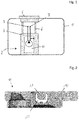
- the Figure 1 shows a schematic view of a fuel tank 1 in a motor vehicle, not shown.
- a fuel delivery unit 2 is arranged in the fuel tank 1 and is formed from a surge pot 3, a fuel delivery pump 4 and a flange 5.
- the flange 5 is used to attach the fuel delivery unit 2 to the fuel tank 1.
- the surge pot 3, which represents a reservoir for the fuel and from which the fuel is delivered to the internal combustion engine by the fuel delivery pump 4, is connected to the flange 5 by means of connecting elements 6.
- the surge pot 3 is also supported against the lower wall of the fuel tank 1.
- the fuel feed pump 4 is arranged inside the surge pot 3 and connected to a voltage source via electrical conductors 7. Both the fuel feed pump 4 and the electrical conductors 7 are bathed by the fuel in the fuel tank 1. It is therefore necessary to ground the metallic elements in contact with the fuel to ensure operational safety.
- the Figure 2 shows a detailed view of the lower section 10 of a pump stage 11.
- the pump stage 11 is usually designed in two parts and has a recess in its interior for receiving the pump wheel.
- the pump stage 11 additionally has openings through which fuel can be delivered into the pump stage 11 and can be delivered out of the pump stage.
- the section 10 has a spherical body 12 which is used as an axial bearing seat for an above and in Figure 2 shaft not shown is used.
- the spherical body 12 is preferably made from an abrasion-resistant material.
- the spherical body 12 is preferably formed from a metallic material.
- the spherical body 12 is arranged in a cup-shaped element 13, which separates the spherical body 12 from the section 10.
- the cup-shaped element 13 is preferably made of an electrically non-conductive material and is used in particular to electrically isolate the spherical body 12 and the shaft (not shown) which is in electrically conductive connection with the spherical body 12 and on which the pump wheel is arranged.
- the cup-shaped element 13 thus forms an electrical insulation element.
- the Figure 3 3 shows a sectional view through a fuel feed pump 15.
- a shaft 16 Centrally in the fuel feed pump 15 is a shaft 16 which is connected to the rotor 17 of the electric motor 18 and is rotatably mounted in the housing 19 of the fuel feed pump 15.
- the shaft 16 is supported on the one hand by a radial bearing 20 and on the other hand by an axial bearing which is formed by the spherical body 12, which is already shown in FIG Figure 2 was shown.
- the housing 19 of the fuel feed pump 15, the pump stage 11 and the stator 22 are connected to the negative pole of the voltage supply or in particular to the ground potential in order to ensure that the elements are earthed.
- the radial bearing 20 is integrated into the upper section 21 of the pump stage 11 and is preferably formed by an electrically insulating material. In this way, an electrically conductive connection between the shaft 16 and the pump stage 11 is prevented.
- an electrically insulating layer or an electrical insulating element can also be arranged between the radial bearing 20 and the pump stage 11 or the upper section 21.
- the shaft 16 is electrically isolated from the earthed elements of the fuel pump 15. This in particular prevents the formation of deposits on the shaft 16 and in particular in the area of the carbon brushes 23 of the electric motor 18, which contributes to an improved service life of the entire fuel feed pump 15.
- Figures 1 to 3 In particular, it is not of a restrictive nature and serves to illustrate the concept of the invention. A wide variety of different structural designs and shapes can also be implemented within the scope encompassed by the invention, without deviating from the basic idea of the invention.
- the execution of the Figures 2 and 3 is an example and illustrates a particularly advantageous possibility of isolating the shaft from the electrically grounded elements of the fuel feed pump without negatively influencing the service life of the fuel feed pump through an unfavorable choice of material, for example plastics for the housing and / or the pump stage.
Landscapes
- Engineering & Computer Science (AREA)
- Mechanical Engineering (AREA)
- General Engineering & Computer Science (AREA)
- Power Engineering (AREA)
- Chemical & Material Sciences (AREA)
- Combustion & Propulsion (AREA)
- Ceramic Engineering (AREA)
- Structures Of Non-Positive Displacement Pumps (AREA)
- Connection Of Motors, Electrical Generators, Mechanical Devices, And The Like (AREA)
Description
- Die Erfindung betrifft eine Kraftstoffförderpumpe zum Fördern von Kraftstoff, mit einem Elektromotor und mit einem durch den Elektromotor antreibbaren Pumpenrad, wobei das Pumpenrad derart mittels einer Welle mit einem Rotor des Elektromotors verbunden ist, dass eine Drehbewegung des Rotors über die Welle auf das Pumpenrad übertragen wird, wobei die Welle durch ein Axiallager in axialer Richtung und/oder durch ein Radiallager in radialer Richtung gegenüber einer Pumpenstufe, in welcher das Pumpenrad angeordnet ist, gelagert ist.
- Kraftstoffförderpumpen werden sowohl von dem zu fördernden Kraftstoff durchströmt als auch von dem Kraftstoff umströmt. Die in Kraftfahrzeugen verwendeten Kraftstoffförderpumpen weisen Elektromotoren auf, die zum Antrieb der Förderstufe, welche beispielsweise durch ein Pumpenrad gebildet ist, verwendet werden. Um eine Sicherheit gegenüber elektrostatischer Entladungen (ESD) sicherzustellen, müssen die elektrisch leitenden Elemente einer Kraftstoffförderpumpe geerdet sein. Dies dient der Verhinderung von Kurzschlüssen und damit dem Entstehen von Funken, die zu einer Entzündung des Kraftstoffes führen könnten. Weiterhin kann die Funktionsfähigkeit der Kraftstoffförderpumpe durch das Entstehen von elektrostatischen Entladungen beeinträchtigt werden. Zu den zu erdenden Teilen gehören insbesondere die Pumpenstufe, das Gehäuse der Kraftstoffförderpumpe und das Motorgehäuse, in welchem der Rotor und der Stator des Elektromotors angeordnet sind.
- Gleichzeitig ist es zu vermeiden, dass die Welle der Kraftstoffförderpumpe, auf welcher die Förderstufe angeordnet ist, mit dem negativen Pol der Spannungsversorgung beziehungsweise mit dem Massepotential kurzgeschlossen wird und somit ebenso geerdet wird. Ein solcher Kurzschluss kann zum Ausfall der Kraftstoffförderpumpe führen oder zu unerwünschten Ablagerungen an der Welle oder dem Rotor, insbesondere in der Nähe der Kohlebürsten. Dies kann zu einer negativen Beeinträchtigung der Lebensdauer der Kraftstoffförderpumpe führen.
- Im Stand der Technik sind unterschiedliche Vorrichtungen bekannt, die mögliche Lösungen des Problems aufzeigen. So sind Kraftstoffförderpumpen bekannt, die zusätzliche Widerstände aufweisen, um eine ausreichende Erdung bzw. Entkopplung zu erreichen. Auch sind Kraftstoffförderpumpen bekannt, die eine Pumpenstufe aus Kunststoff aufweisen, wodurch eine Isolation der Welle erreicht werde kann. Weiterhin sind Kraftstoffförderpumpen bekannt, die eine Erdung des Motorgehäuses und somit auch eine Erdung der Welle vorsehen.
- Nachteilig an den Vorrichtungen im Stand der Technik ist insbesondere, dass entweder keine ausreichende Sicherheit gegen elektrostatische Entladungen erreicht werden kann oder durch die Erdung des Motorgehäuses auch eine Erdung der Welle erzeugt wird, wodurch sich Ablagerungen im Inneren des Elektromotors ergeben können. Die Ausführung der Pumpenstufe als Kunststoffbauteil führt zu einer niedrigeren Stabilität und somit zu einer verkürzten Lebensdauer.
- Die
JP H04 203287 A JP 2004 092484 A JP H04 203288 A CN 201 202 729 Y und dieUS 4 619 588 A betreffen Kraftstoffförderpumpen und Lagerungen von Wellen mit dran angeordneten Pumpenrädern. - Daher ist es die Aufgabe der vorliegenden Erfindung eine Kraftstoffförderpumpe zu schaffen, welche eine ausreichende Sicherheit gegen elektrostatische Entladungen aufweist und gleichzeitig eine elektrische Entkopplung der Welle gegenüber den geerdeten Elementen aufweist.
- Die Aufgabe hinsichtlich der Kraftstoffförderpumpe wird durch eine Kraftstoffförderpumpe mit den Merkmalen von Anspruch 1 gelöst.
- Erfindungsgemäß wird eine Kraftstoffförderpumpe zum Fördern von Kraftstoff offenbart, mit einem Elektromotor und mit einem durch den Elektromotor antreibbaren Pumpenrad, wobei das Pumpenrad derart mittels einer Welle mit einem Rotor des Elektromotors verbunden ist, dass eine Drehbewegung des Rotors über die Welle auf das Pumpenrad übertragen wird, wobei die Welle durch ein Axiallager in axialer Richtung gegenüber einer Pumpenstufe, in welcher das Pumpenrad angeordnet ist, gelagert ist, wobei zwischen dem Axiallager und der Pumpenstufe ein elektrisches Isolationselement angeordnet ist, und wobei das elektrische Isolationselement zwischen dem Axiallager und der Pumpenstufe durch ein topfförmiges Element gebildet ist.
- Bevorzugt ist sowohl zwischen dem Radiallager und der Pumpenstufe als auch zwischen dem Axiallager und der Pumpenstufe ein elektrisches Isolationselement angeordnet. Hierdurch kann eine umfassende elektrische Isolation der Welle erreicht werden.
- Durch die Anordnung von elektrischen Isolationselementen zwischen dem Axiallager und der Pumpenstufe und/oder zwischen dem Radiallager und der Pumpenstufe kann eine elektrische Isolation der Welle von der Pumpenstufe und somit von dem Gehäuse der Kraftstoffförderpumpe und dem Motorgehäuse erzeugt werden. Dies ist besonders vorteilhaft, um Ablagerungen im Bereich der Welle aufgrund einer Polarität der Welle zu vermeiden. Durch die elektrische Isolation kann das Gehäuse der Kraftstoffförderpumpe, das Motorgehäuse und die Pumpenstufe mit dem negativen Pol der Spannungsversorgung beziehungsweise dem Massenpotential verbunden werden und somit einer Erdung der genannten Elemente erreicht werden. Dies ist vorteilhaft, um Kurzschlüsse und elektrostatische Entladungen zu vermeiden.
- Das Motorgehäuse kann beispielsweise durch den Stator des Elektromotors gebildet sein. Ebenso kann eine käfigartige Struktur um den Stator herum angeordnet sein, welche als Motorgehäuse fungiert. Durch das Einsetzten des Elektromotors in das Gehäuse der Kraftstoffförderpumpe ist der Elektromotor auch ohne ein geschlossenes eigenes Gehäuse ausreichend gegen mechanische Störeinflüsse geschützt.
- Besonders vorteilhaft ist es, wenn das Radiallager als elektrisches Isolationselement ausgebildet ist. Um ein zusätzliches Isolationselement einzusparen, kann das Radiallager neben der Funktion der Lagerung auch die Funktion der elektrischen Isolation übernehmen. Hierzu kann das Radiallager besonders bevorzugt aus einem elektrisch nicht leitfähigen Material ausgebildet sein. Beispielsweise können die Lagerschalen aus Kunststoff oder einer nicht leitfähigen Keramik ausgebildet sein. Auch kann das Radiallager mit einer elektrisch nicht leitfähigen Beschichtung beschichtet sein.
- Das elektrische Isolationselement zwischen dem Axiallager und der Pumpenstufe ist durch ein topfförmiges Element gebildet. Ein topfförmiges Element ist vorteilhaft, um einen sicheren Sitz des Axiallagers zu gewährleisten und darüber hinaus eine einfache Montage des Isolationselementes zu ermöglichen. Hierzu kann ein passgenauer Ausschnitt im unteren Abschnitt der Pumpenstufe vorgesehen werden, in welchen das Isolationselement eingesetzt oder eingepresst werden kann.
- Die Pumpenstufe ist bevorzugt durch ein zweiteiliges Gehäuse gebildet, welches den unteren Abschluss des Gehäuses der Kraftstoffförderpumpe bildet. In der Pumpenstufe ist das Pumpenrad angeordnet. Die Pumpenstufe weist zusätzlich Öffnungen zum Ansaugen und Ausstoßen des zu fördernden Fluids auf.
- Auch ist es zu bevorzugen, wenn das Axiallager durch einen kugelförmigen Körper gebildet ist, wobei der kugelförmige Körper in dem topfförmigen elektrischen Isolationselement angeordnet ist. Ein kugelförmiger Körper ist vorteilhaft, da die Welle in axialer Richtung abgestützt und gelagert werden kann, wobei nur eine sehr geringe Kontaktfläche zwischen der Welle und dem kugelförmigen Körper entsteht. Der kugelförmige Körper kann bevorzugt in die Aussparung der Pumpenstufe, in welche bereits das Isolationselement eingesetzt ist, eingepresst werden, so dass der kugelförmige Körper fest in der Pumpenstufe aufgenommen ist. Alternativ ist auch ein Abgleiten des kugelförmigen Körpers auf dem Isolationselement vorsehbar, wodurch das Axiallager letztlich sowohl durch den kugelförmigen Körper als auch durch das topfförmige Isolationselement gebildet wird.
- Darüber hinaus ist es vorteilhaft, wenn das elektrische Isolationselement durch eine elektrisch nicht leitfähige Beschichtung gebildet ist. Eine elektrisch nicht leitfähige Beschichtung der Pumpenstufe im Bereich des Axiallagers und/oder des Radiallagers ist vorteilhaft, da somit ebenfalls eine elektrische Isolation erreicht werden kann. Die Beschichtung ist bevorzugt durch elektrisch nicht leitfähige Materialien, wie beispielsweise Kunststoff oder Keramik gebildet.
- Weiterhin ist es vorteilhaft, wenn zumindest eines der elektrischen Isolationselemente aus einem Kunststoff und/oder einer Keramik gebildet ist. Dabei ist es insbesondere vorteilhaft, wenn zumindest eines der elektrischen Isolationselemente aus einem thermoplastischen Material gebildet ist.
- Darüber hinaus ist es vorteilhaft, wenn zwischen der Welle und der Pumpenstufe ein elektrisch nicht leitfähiges Dichtungselement angeordnet ist. Das Dichtungselement kann beispielsweise eine Keramik sein oder ein Gummielement. Vorteilhafte Weiterbildungen der vorliegenden Erfindung sind in den Unteransprüchen und in der nachfolgenden Figurenbeschreibung beschrieben.
- Im Folgenden wird die Erfindung anhand von einem Ausführungsbeispiel unter Bezugnahme auf die Zeichnungen detailliert erläutert. In den Zeichnungen zeigen:
- Fig. 1
- eine Prinzipskizze, die eine Anordnung einer Kraftstoffförderpumpe in einem Kraftstofftank zeigt,
- Fig. 2
- eine Detailansicht des unteren Abschnitts der Pumpenstufe, wobei insbesondere das topfförmige Isolationselement und der kugelförmige Körper, der als Axiallager dient, gezeigt sind, und
- Fig. 3
- eine Schnittansicht durch eine Kraftstoffförderpumpe, wobei ein elektrisch nicht leitfähiges Radiallager zwischen der Welle und der Pumpenstufe angeordnet ist und ein elektrisch nicht leitfähiges topfförmiges Isolationselement zwischen dem nach unten gerichteten axialen Endbereich der Welle und der Pumpenstufe angeordnet ist.
- Die
Figur 1 zeigt eine schematische Ansicht eines Kraftstofftanks 1 in einem nicht dargestellten Kraftfahrzeug. Im Kraftstofftank 1 ist eine Kraftstofffördereinheit 2 angeordnet, die aus einem Schwalltopf 3, einer Kraftstoffförderpumpe 4 und einem Flansch 5 gebildet ist. Der Flansch 5 dient der Befestigung der Kraftstofffördereinheit 2 an dem Kraftstofftank 1. Der Schwalltopf 3, welcher ein Reservoir für den Kraftstoff darstellt und aus welchem der Kraftstoff durch die Kraftstoffförderpumpe 4 zum Verbrennungsmotor gefördert wird, ist mittels Verbindungselementen 6 mit dem Flansch 5 verbunden. Der Schwalltopf 3 ist weiterhin gegenüber der unteren Wandung des Kraftstofftanks 1 abgestützt. - Die Kraftstoffförderpumpe 4 ist innerhalb des Schwalltopfes 3 angeordnet und über elektrische Leiter 7 mit einer Spannungsquelle verbunden. Sowohl die Kraftstoffförderpumpe 4 als auch die elektrischen Leiter 7 sind von dem Kraftstoff im Kraftstofftank 1 umspült. Daher ist zur Gewährleistung der Betriebssicherheit eine Erdung der metallischen mit dem Kraftstoff in Kontakt stehenden Elemente notwendig.
- Die
Figur 2 zeigt eine Detailansicht des unteren Abschnitts 10 einer Pumpenstufe 11. Die Pumpenstufe 11 ist regelmäßig zweiteilig ausgeführt und weist in ihrem Inneren eine Ausnehmung zur Aufnahme des Pumpenrades auf. Die Pumpenstufe 11 weist zusätzlich Öffnungen auf, durch welchen Kraftstoff in die Pumpenstufe 11 hinein gefördert werden kann und aus der Pumpenstufe heraus gefördert werden kann. - Der Abschnitt 10 weist einen kugelförmigen Körper 12 auf, welcher als axialer Lagersitz für eine darüber angeordnete und in
Figur 2 nicht gezeigte Welle dient. Der kugelförmige Körper 12 ist bevorzugt aus einem abriebfesten Material erzeugt. Vorzugsweise ist der kugelförmige Körper 12 aus einem metallischen Material gebildet. Der kugelförmige Körper 12 ist in einem topfförmigen Element 13 angeordnet, welches den kugelförmigen Körper 12 zum Abschnitt 10 beabstandet. Das topfförmige Element 13 ist bevorzugt aus einem elektrisch nicht leitfähigen Material gebildet und dient insbesondere der elektrischen Isolation des kugelförmigen Körpers 12 und der mit dem kugelförmigen Körper 12 in elektrisch leitender Verbindung stehenden nicht gezeigten Welle, auf welcher das Pumpenrad angeordnet ist. Das topfförmige Element 13 bildet somit ein elektrisches Isolationselement aus. - Die
Figur 3 zeigt eine Schnittansicht durch eine Kraftstoffförderpumpe 15. Zentral in der Kraftstoffförderpumpe 15 ist eine Welle 16 angeordnet, welche mit dem Rotor 17 des Elektromotors 18 verbunden ist und drehbar im Gehäuse 19 der Kraftstoffförderpumpe 15 gelagert ist. - Die Welle 16 ist einerseits durch ein Radiallager 20 gelagert und andererseits durch ein Axiallager, welches durch den kugelförmigen Körper 12 gebildet ist, der bereits in
Figur 2 gezeigt wurde. - Insbesondere das Gehäuse 19 der Kraftstoffförderpumpe 15, die Pumpenstufe 11 und der Stator 22 sind mit dem negativen Pol der Spannungsversorgung beziehungsweise insbesondere mit dem Massenpotential verbunden, um eine Erdung der Elemente sicherzustellen.
- Das Radiallager 20 ist in den oberen Abschnitt 21 der Pumpenstufe 11 integriert und ist bevorzugt durch ein elektrisch isolierendes Material gebildet. Auf diese Weise wird eine elektrisch leitende Verbindung zwischen der Welle 16 und der Pumpenstufe 11 verhindert. Alternativ kann zwischen dem Radiallager 20 und der Pumpenstufe 11 beziehungsweise dem oberen Abschnitt 21 auch eine elektrisch isolierende Schicht oder ein elektrisches Isolationselement angeordnet sein.
- Durch die Kombination eines elektrisch nicht leitfähigen Radiallagers 20 oder eines Isolationselementes zwischen dem Radiallager 20 und der Pumpenstufe 11 und dem topfförmigen Körper 13 aus einem elektrisch isolierenden Material, ist eine elektrische Isolation der Welle 16 gegenüber den geerdeten Elemente der Kraftstoffförderpumpe 15 erreicht. Dies verhindert insbesondere das Entstehen von Ablagerungen an der Welle 16 und insbesondere im Bereich der Kohlebürsten 23 des Elektromotors 18, was zu einer verbesserten Lebensdauer der gesamten Kraftstoffförderpumpe 15 beiträgt.
- Das Ausführungsbeispiel der
Figuren 1 bis 3 weist insbesondere keinen beschränkenden Charakter auf und dient der Verdeutlichung des Erfindungsgedankens. Auch vielfältige abweichende konstruktive Gestaltungen und Formgebungen können im von der Erfindung umfassten Rahmen realisiert werden, ohne dabei von dem Grundgedanken der Erfindung abzuweichen. Die Ausführung derFiguren 2 und3 ist beispielhaft und verdeutlicht eine besonders vorteilhafte Möglichkeit eine Isolation der Welle von den elektrisch geerdeten Elementen der Kraftstoffförderpumpe zu erreichen ohne dabei die Lebensdauer der Kraftstoffförderpumpe durch eine ungünstige Materialwahl, beispielsweise durch Kunststoffe für das Gehäuse und/oder die Pumpenstufe, negativ zu beeinflussen.
Claims (8)
- Kraftstoffförderpumpe (4, 15) zum Fördern von Kraftstoff, mit einem Elektromotor (18) und mit einem durch den Elektromotor (18) antreibbaren Pumpenrad, wobei das Pumpenrad derart mittels einer Welle (16) mit einem Rotor (17) des Elektromotors (18) verbunden ist, dass eine Drehbewegung des Rotors (17) über die Welle (16) auf das Pumpenrad übertragen wird, wobei die Welle (16) durch ein Axiallager (12) in axialer Richtung gegenüber einer Pumpenstufe (11), in welcher das Pumpenrad angeordnet ist, gelagert ist, wobei zwischen dem Axiallager (12) und der Pumpenstufe (11) ein elektrisches Isolationselement (13) angeordnet ist, und wobei das elektrische Isolationselement (13) zwischen dem Axiallager (12) und der Pumpenstufe (11) durch ein topfförmiges Element (13) gebildet ist.
- Kraftstoffförderpumpe (4, 15) nach Anspruch 1,
dadurch gekennzeichnet, dass die Welle (16) durch ein Radiallager (20) in radialer Richtung gegenüber der Pumpenstufe (11) gelagert ist, wobei zwischen dem Radiallager (20) und der Pumpenstufe (11) ein elektrisches Isolationselement angeordnet ist. - Kraftstoffförderpumpe (4, 15) nach Anspruch 1,
dadurch gekennzeichnet, dass die Welle (16) durch ein Radiallager (20) in radialer Richtung gegenüber der Pumpenstufe (11) gelagert ist, wobei das Radiallager (20) als elektrisches Isolationselement ausgebildet ist. - Kraftstoffförderpumpe (4, 15) nach Anspruch 1, 2 oder 3,
dadurch gekennzeichnet, dass das Axiallager (12) durch einen kugelförmigen Körper (12) gebildet ist, wobei der kugelförmige Körper (12) in dem topfförmigen elektrischen Isolationselement (13) angeordnet ist. - Kraftstoffförderpumpe (4, 15) nach einem der Ansprüche 1, 2 oder 4 in Verbindung mit Anspruch 1 oder 2,
dadurch gekennzeichnet, dass zumindest eines der elektrischen Isolationselemente (13) durch eine elektrisch nicht leitfähige Beschichtung gebildet ist. - Kraftstoffförderpumpe (4, 15) nach einem der vorhergehenden Ansprüche, dadurch gekennzeichnet, dass zumindest eines der elektrischen Isolationselemente (13) aus einem Kunststoff und/oder einer Keramik gebildet ist.
- Kraftstoffförderpumpe (4, 15) nach einem der vorhergehenden Ansprüche, dadurch gekennzeichnet, dass zumindest eines der elektrischen Isolationselemente (13, 20) aus einem thermoplastischen Material gebildet ist.
- Kraftstoffförderpumpe (4, 15) nach einem der vorhergehenden Ansprüche, dadurch gekennzeichnet, dass zwischen der Welle (16) und der Pumpenstufe (11) ein elektrisch nicht leitfähiges Dichtungselement angeordnet ist.
Applications Claiming Priority (2)
| Application Number | Priority Date | Filing Date | Title |
|---|---|---|---|
| DE102015213420.2A DE102015213420A1 (de) | 2015-07-16 | 2015-07-16 | Kraftstoffförderpumpe |
| PCT/EP2016/065687 WO2017009082A1 (de) | 2015-07-16 | 2016-07-04 | Kraftstoffförderpumpe |
Publications (2)
| Publication Number | Publication Date |
|---|---|
| EP3322890A1 EP3322890A1 (de) | 2018-05-23 |
| EP3322890B1 true EP3322890B1 (de) | 2020-09-09 |
Family
ID=56360395
Family Applications (1)
| Application Number | Title | Priority Date | Filing Date |
|---|---|---|---|
| EP16735641.9A Active EP3322890B1 (de) | 2015-07-16 | 2016-07-04 | Kraftstoffförderpumpe |
Country Status (7)
| Country | Link |
|---|---|
| US (1) | US10330108B2 (de) |
| EP (1) | EP3322890B1 (de) |
| JP (1) | JP6588149B2 (de) |
| KR (1) | KR102594015B1 (de) |
| CN (1) | CN107690743B (de) |
| DE (1) | DE102015213420A1 (de) |
| WO (1) | WO2017009082A1 (de) |
Families Citing this family (2)
| Publication number | Priority date | Publication date | Assignee | Title |
|---|---|---|---|---|
| DE102017210771B4 (de) * | 2017-06-27 | 2019-05-29 | Continental Automotive Gmbh | Schraubenspindelpumpe, Kraftstoffförderaggregat und Kraftstofffördereinheit |
| US12018680B2 (en) | 2022-04-12 | 2024-06-25 | Phinia Delphi Luxembourg Sarl | Fluid pump with thrust bearing driver |
Family Cites Families (25)
| Publication number | Priority date | Publication date | Assignee | Title |
|---|---|---|---|---|
| US3658444A (en) | 1970-05-20 | 1972-04-25 | Holley Carburetor Co | Holley fuel pump |
| US3666381A (en) | 1970-05-20 | 1972-05-30 | United Ind Syndicate | Submersible fuel pump |
| DE2245009C3 (de) | 1972-09-14 | 1979-09-13 | Eheim, Gunther, 7301 Deizisau | Spaltrohrmotor für ein Pumpenaggregat mit Kunststoffgehäuse und mit Pumpenrad vereinigtem Rotor |
| US4699573A (en) * | 1981-10-13 | 1987-10-13 | Westinghouse Electric Corp. | Transformer oil pump bearing material |
| US4619588A (en) * | 1984-04-25 | 1986-10-28 | Facet Enterprises, Incorporated | Wet motor gerotor fuel pump with vapor vent valve and improved flow through the armature |
| GB2243250B (en) | 1990-04-17 | 1994-08-03 | Mitsubishi Electric Corp | An in-tank type motor-operated pump incorporating an electrical noise suppressor |
| JPH04203287A (ja) * | 1990-11-29 | 1992-07-23 | Keihin Seiki Mfg Co Ltd | 車輌用燃料ポンプ |
| JPH04203288A (ja) * | 1990-11-29 | 1992-07-23 | Keihin Seiki Mfg Co Ltd | 車輌用燃料ポンプ |
| US5173037A (en) * | 1991-12-09 | 1992-12-22 | General Motors Corporation | Automotive fuel pump |
| DE69211516T2 (de) | 1991-12-30 | 1997-01-02 | Molex Inc | Elektrische Anschlussanordnung mit Anschlussverriegelungselement |
| DE19634253A1 (de) * | 1995-12-30 | 1997-07-03 | Bosch Gmbh Robert | Aggregat zum Fördern von Kraftstoff |
| US6736616B2 (en) * | 2002-05-20 | 2004-05-18 | Oliver Laing | Centrifugal pump with integrated motor |
| JP2004092484A (ja) * | 2002-08-30 | 2004-03-25 | Denso Corp | 燃料ポンプ |
| JP2004263563A (ja) * | 2003-01-16 | 2004-09-24 | Mitsuba Corp | 燃料ポンプユニット |
| JP4158154B2 (ja) | 2004-01-14 | 2008-10-01 | 株式会社デンソー | 電動機およびそれを用いた燃料ポンプ |
| JP4252507B2 (ja) * | 2004-07-09 | 2009-04-08 | 愛三工業株式会社 | 燃料ポンプ |
| JP3129498U (ja) * | 2006-08-11 | 2007-02-22 | 建軍 ▲兪▼ | 磁気浮上回転装置 |
| JP4561761B2 (ja) * | 2007-03-07 | 2010-10-13 | 三菱電機株式会社 | 燃料供給装置 |
| DE102007025510A1 (de) * | 2007-06-01 | 2008-12-04 | Continental Automotive Gmbh | Kraftstoffpumpe |
| CN201202729Y (zh) * | 2008-01-08 | 2009-03-04 | 陈志林 | 环形轴承 |
| JP5515246B2 (ja) * | 2008-07-08 | 2014-06-11 | 株式会社ジェイテクト | 車軸用軸受装置 |
| US8602753B2 (en) * | 2009-09-21 | 2013-12-10 | Flowserve Management Company | Radial bearings for deep well submersible pumps |
| JP2012031808A (ja) * | 2010-08-02 | 2012-02-16 | Denso Corp | 燃料ポンプ |
| DE102011085884B4 (de) * | 2011-11-08 | 2021-10-21 | Zf Friedrichshafen Ag | Drehmomentübertragungseinrichtung mit elektrischer Isolierung |
| JP2014099968A (ja) * | 2012-11-13 | 2014-05-29 | Nidec Sankyo Corp | モータ、およびモータの検査方法 |
-
2015
- 2015-07-16 DE DE102015213420.2A patent/DE102015213420A1/de not_active Withdrawn
-
2016
- 2016-07-04 CN CN201680033662.6A patent/CN107690743B/zh active Active
- 2016-07-04 JP JP2018501945A patent/JP6588149B2/ja active Active
- 2016-07-04 KR KR1020187000778A patent/KR102594015B1/ko active Active
- 2016-07-04 WO PCT/EP2016/065687 patent/WO2017009082A1/de not_active Ceased
- 2016-07-04 EP EP16735641.9A patent/EP3322890B1/de active Active
-
2018
- 2018-01-16 US US15/872,502 patent/US10330108B2/en active Active
Non-Patent Citations (1)
| Title |
|---|
| None * |
Also Published As
| Publication number | Publication date |
|---|---|
| DE102015213420A1 (de) | 2017-03-30 |
| CN107690743B (zh) | 2020-04-07 |
| JP6588149B2 (ja) | 2019-10-09 |
| KR102594015B1 (ko) | 2023-10-26 |
| JP2018522161A (ja) | 2018-08-09 |
| US20180138775A1 (en) | 2018-05-17 |
| KR20180030029A (ko) | 2018-03-21 |
| EP3322890A1 (de) | 2018-05-23 |
| US10330108B2 (en) | 2019-06-25 |
| WO2017009082A1 (de) | 2017-01-19 |
| CN107690743A (zh) | 2018-02-13 |
Similar Documents
| Publication | Publication Date | Title |
|---|---|---|
| DE102009002953B4 (de) | Schwungrad, Brennkraftmaschine mit Schwungrad sowie System aus einer Brennkraftmaschine und einer anzutreibenden Maschine, Verwendung des Systems | |
| EP3447312A1 (de) | Aufladevorrichtung für eine brennkraftmaschine | |
| DE102017218287B4 (de) | Kraftstoffpumpe und Kraftstofffördereinheit | |
| WO2019072887A1 (de) | Kraftstoffpumpe und kraftstofffördereinheit | |
| WO2021239807A1 (de) | Antriebseinheit für ein elektrisch angetriebenes fahrzeug | |
| WO2010094375A1 (de) | Kühlmittelpumpe für fahrzeuge | |
| WO2011026678A1 (de) | Zweistufige kreiselpumpe | |
| DE102014213698A1 (de) | Elektrische Maschine mit einem Widerstand zur Ableitung von Wellenspannungen | |
| WO2016206887A1 (de) | Verbesserte elektromagnetische verträglichkeit einer antriebsanordnung für ein elektrisch angetriebenes fahrzeug | |
| DE102015213420A1 (de) | Kraftstoffförderpumpe | |
| DE102016209311A1 (de) | Elektrische kreiselpumpe | |
| DE1528697C3 (de) | Pumpe, insbesondere Faßpumpe | |
| WO2013113545A2 (de) | Pumpe mit elektromotor | |
| DE102017218285A1 (de) | Kraftstoffpumpe und Kraftstofffördereinheit | |
| DE4338345A1 (de) | Elektromotor zum Antrieb von Kraftstofförderpumpen für Brennkraftmaschinen | |
| WO2014095405A2 (de) | Verfahren zur herstellung eines elektromotors und elektromotor | |
| WO2023099399A1 (de) | Antriebseinheit zum motorischen verstellen eines verschlusselements eines kraftfahrzeugs | |
| DE102011076025A1 (de) | Pumpe mit Elektromotor | |
| EP3084219A1 (de) | Pumpenvorrichtung | |
| WO2012038199A2 (de) | Pumpe mit elektromotor | |
| WO2012038214A2 (de) | Pumpe mit elektromotor | |
| DE102011005304A1 (de) | Pumpe mit Elektromotor | |
| EP2756195A1 (de) | Pumpe mit elektromotor | |
| WO2018220156A1 (de) | Leitungsdurchführung | |
| DE20306902U1 (de) | Kollektorloser Elektromotor |
Legal Events
| Date | Code | Title | Description |
|---|---|---|---|
| STAA | Information on the status of an ep patent application or granted ep patent |
Free format text: STATUS: THE INTERNATIONAL PUBLICATION HAS BEEN MADE |
|
| PUAI | Public reference made under article 153(3) epc to a published international application that has entered the european phase |
Free format text: ORIGINAL CODE: 0009012 |
|
| STAA | Information on the status of an ep patent application or granted ep patent |
Free format text: STATUS: REQUEST FOR EXAMINATION WAS MADE |
|
| 17P | Request for examination filed |
Effective date: 20180216 |
|
| AK | Designated contracting states |
Kind code of ref document: A1 Designated state(s): AL AT BE BG CH CY CZ DE DK EE ES FI FR GB GR HR HU IE IS IT LI LT LU LV MC MK MT NL NO PL PT RO RS SE SI SK SM TR |
|
| AX | Request for extension of the european patent |
Extension state: BA ME |
|
| DAV | Request for validation of the european patent (deleted) | ||
| DAX | Request for extension of the european patent (deleted) | ||
| STAA | Information on the status of an ep patent application or granted ep patent |
Free format text: STATUS: EXAMINATION IS IN PROGRESS |
|
| 17Q | First examination report despatched |
Effective date: 20190205 |
|
| GRAP | Despatch of communication of intention to grant a patent |
Free format text: ORIGINAL CODE: EPIDOSNIGR1 |
|
| STAA | Information on the status of an ep patent application or granted ep patent |
Free format text: STATUS: GRANT OF PATENT IS INTENDED |
|
| INTG | Intention to grant announced |
Effective date: 20200211 |
|
| RAP1 | Party data changed (applicant data changed or rights of an application transferred) |
Owner name: VITESCO TECHNOLOGIES GMBH |
|
| GRAS | Grant fee paid |
Free format text: ORIGINAL CODE: EPIDOSNIGR3 |
|
| GRAA | (expected) grant |
Free format text: ORIGINAL CODE: 0009210 |
|
| STAA | Information on the status of an ep patent application or granted ep patent |
Free format text: STATUS: THE PATENT HAS BEEN GRANTED |
|
| AK | Designated contracting states |
Kind code of ref document: B1 Designated state(s): AL AT BE BG CH CY CZ DE DK EE ES FI FR GB GR HR HU IE IS IT LI LT LU LV MC MK MT NL NO PL PT RO RS SE SI SK SM TR |
|
| REG | Reference to a national code |
Ref country code: GB Ref legal event code: FG4D Free format text: NOT ENGLISH |
|
| REG | Reference to a national code |
Ref country code: AT Ref legal event code: REF Ref document number: 1311880 Country of ref document: AT Kind code of ref document: T Effective date: 20200915 Ref country code: CH Ref legal event code: EP |
|
| REG | Reference to a national code |
Ref country code: IE Ref legal event code: FG4D Free format text: LANGUAGE OF EP DOCUMENT: GERMAN |
|
| REG | Reference to a national code |
Ref country code: DE Ref legal event code: R096 Ref document number: 502016011118 Country of ref document: DE |
|
| REG | Reference to a national code |
Ref country code: LT Ref legal event code: MG4D |
|
| PG25 | Lapsed in a contracting state [announced via postgrant information from national office to epo] |
Ref country code: NO Free format text: LAPSE BECAUSE OF FAILURE TO SUBMIT A TRANSLATION OF THE DESCRIPTION OR TO PAY THE FEE WITHIN THE PRESCRIBED TIME-LIMIT Effective date: 20201209 Ref country code: BG Free format text: LAPSE BECAUSE OF FAILURE TO SUBMIT A TRANSLATION OF THE DESCRIPTION OR TO PAY THE FEE WITHIN THE PRESCRIBED TIME-LIMIT Effective date: 20201209 Ref country code: HR Free format text: LAPSE BECAUSE OF FAILURE TO SUBMIT A TRANSLATION OF THE DESCRIPTION OR TO PAY THE FEE WITHIN THE PRESCRIBED TIME-LIMIT Effective date: 20200909 Ref country code: LT Free format text: LAPSE BECAUSE OF FAILURE TO SUBMIT A TRANSLATION OF THE DESCRIPTION OR TO PAY THE FEE WITHIN THE PRESCRIBED TIME-LIMIT Effective date: 20200909 Ref country code: GR Free format text: LAPSE BECAUSE OF FAILURE TO SUBMIT A TRANSLATION OF THE DESCRIPTION OR TO PAY THE FEE WITHIN THE PRESCRIBED TIME-LIMIT Effective date: 20201210 Ref country code: FI Free format text: LAPSE BECAUSE OF FAILURE TO SUBMIT A TRANSLATION OF THE DESCRIPTION OR TO PAY THE FEE WITHIN THE PRESCRIBED TIME-LIMIT Effective date: 20200909 Ref country code: SE Free format text: LAPSE BECAUSE OF FAILURE TO SUBMIT A TRANSLATION OF THE DESCRIPTION OR TO PAY THE FEE WITHIN THE PRESCRIBED TIME-LIMIT Effective date: 20200909 |
|
| REG | Reference to a national code |
Ref country code: NL Ref legal event code: MP Effective date: 20200909 |
|
| PG25 | Lapsed in a contracting state [announced via postgrant information from national office to epo] |
Ref country code: LV Free format text: LAPSE BECAUSE OF FAILURE TO SUBMIT A TRANSLATION OF THE DESCRIPTION OR TO PAY THE FEE WITHIN THE PRESCRIBED TIME-LIMIT Effective date: 20200909 Ref country code: RS Free format text: LAPSE BECAUSE OF FAILURE TO SUBMIT A TRANSLATION OF THE DESCRIPTION OR TO PAY THE FEE WITHIN THE PRESCRIBED TIME-LIMIT Effective date: 20200909 Ref country code: PL Free format text: LAPSE BECAUSE OF FAILURE TO SUBMIT A TRANSLATION OF THE DESCRIPTION OR TO PAY THE FEE WITHIN THE PRESCRIBED TIME-LIMIT Effective date: 20200909 |
|
| PG25 | Lapsed in a contracting state [announced via postgrant information from national office to epo] |
Ref country code: EE Free format text: LAPSE BECAUSE OF FAILURE TO SUBMIT A TRANSLATION OF THE DESCRIPTION OR TO PAY THE FEE WITHIN THE PRESCRIBED TIME-LIMIT Effective date: 20200909 Ref country code: SM Free format text: LAPSE BECAUSE OF FAILURE TO SUBMIT A TRANSLATION OF THE DESCRIPTION OR TO PAY THE FEE WITHIN THE PRESCRIBED TIME-LIMIT Effective date: 20200909 Ref country code: PT Free format text: LAPSE BECAUSE OF FAILURE TO SUBMIT A TRANSLATION OF THE DESCRIPTION OR TO PAY THE FEE WITHIN THE PRESCRIBED TIME-LIMIT Effective date: 20210111 Ref country code: RO Free format text: LAPSE BECAUSE OF FAILURE TO SUBMIT A TRANSLATION OF THE DESCRIPTION OR TO PAY THE FEE WITHIN THE PRESCRIBED TIME-LIMIT Effective date: 20200909 Ref country code: CZ Free format text: LAPSE BECAUSE OF FAILURE TO SUBMIT A TRANSLATION OF THE DESCRIPTION OR TO PAY THE FEE WITHIN THE PRESCRIBED TIME-LIMIT Effective date: 20200909 |
|
| PG25 | Lapsed in a contracting state [announced via postgrant information from national office to epo] |
Ref country code: IS Free format text: LAPSE BECAUSE OF FAILURE TO SUBMIT A TRANSLATION OF THE DESCRIPTION OR TO PAY THE FEE WITHIN THE PRESCRIBED TIME-LIMIT Effective date: 20210109 Ref country code: ES Free format text: LAPSE BECAUSE OF FAILURE TO SUBMIT A TRANSLATION OF THE DESCRIPTION OR TO PAY THE FEE WITHIN THE PRESCRIBED TIME-LIMIT Effective date: 20200909 Ref country code: AL Free format text: LAPSE BECAUSE OF FAILURE TO SUBMIT A TRANSLATION OF THE DESCRIPTION OR TO PAY THE FEE WITHIN THE PRESCRIBED TIME-LIMIT Effective date: 20200909 |
|
| REG | Reference to a national code |
Ref country code: DE Ref legal event code: R097 Ref document number: 502016011118 Country of ref document: DE |
|
| PG25 | Lapsed in a contracting state [announced via postgrant information from national office to epo] |
Ref country code: SK Free format text: LAPSE BECAUSE OF FAILURE TO SUBMIT A TRANSLATION OF THE DESCRIPTION OR TO PAY THE FEE WITHIN THE PRESCRIBED TIME-LIMIT Effective date: 20200909 |
|
| PLBE | No opposition filed within time limit |
Free format text: ORIGINAL CODE: 0009261 |
|
| STAA | Information on the status of an ep patent application or granted ep patent |
Free format text: STATUS: NO OPPOSITION FILED WITHIN TIME LIMIT |
|
| 26N | No opposition filed |
Effective date: 20210610 |
|
| PG25 | Lapsed in a contracting state [announced via postgrant information from national office to epo] |
Ref country code: SI Free format text: LAPSE BECAUSE OF FAILURE TO SUBMIT A TRANSLATION OF THE DESCRIPTION OR TO PAY THE FEE WITHIN THE PRESCRIBED TIME-LIMIT Effective date: 20200909 Ref country code: DK Free format text: LAPSE BECAUSE OF FAILURE TO SUBMIT A TRANSLATION OF THE DESCRIPTION OR TO PAY THE FEE WITHIN THE PRESCRIBED TIME-LIMIT Effective date: 20200909 |
|
| PG25 | Lapsed in a contracting state [announced via postgrant information from national office to epo] |
Ref country code: IT Free format text: LAPSE BECAUSE OF FAILURE TO SUBMIT A TRANSLATION OF THE DESCRIPTION OR TO PAY THE FEE WITHIN THE PRESCRIBED TIME-LIMIT Effective date: 20200909 |
|
| REG | Reference to a national code |
Ref country code: DE Ref legal event code: R081 Ref document number: 502016011118 Country of ref document: DE Owner name: SCHAEFFLER TECHNOLOGIES AG & CO. KG, DE Free format text: FORMER OWNER: VITESCO TECHNOLOGIES GMBH, 30165 HANNOVER, DE Ref country code: DE Ref legal event code: R081 Ref document number: 502016011118 Country of ref document: DE Owner name: VITESCO TECHNOLOGIES GMBH, DE Free format text: FORMER OWNER: VITESCO TECHNOLOGIES GMBH, 30165 HANNOVER, DE |
|
| REG | Reference to a national code |
Ref country code: CH Ref legal event code: PL |
|
| GBPC | Gb: european patent ceased through non-payment of renewal fee |
Effective date: 20210704 |
|
| PG25 | Lapsed in a contracting state [announced via postgrant information from national office to epo] |
Ref country code: MC Free format text: LAPSE BECAUSE OF FAILURE TO SUBMIT A TRANSLATION OF THE DESCRIPTION OR TO PAY THE FEE WITHIN THE PRESCRIBED TIME-LIMIT Effective date: 20200909 |
|
| REG | Reference to a national code |
Ref country code: BE Ref legal event code: MM Effective date: 20210731 |
|
| PG25 | Lapsed in a contracting state [announced via postgrant information from national office to epo] |
Ref country code: LI Free format text: LAPSE BECAUSE OF NON-PAYMENT OF DUE FEES Effective date: 20210731 Ref country code: GB Free format text: LAPSE BECAUSE OF NON-PAYMENT OF DUE FEES Effective date: 20210704 Ref country code: CH Free format text: LAPSE BECAUSE OF NON-PAYMENT OF DUE FEES Effective date: 20210731 |
|
| PG25 | Lapsed in a contracting state [announced via postgrant information from national office to epo] |
Ref country code: LU Free format text: LAPSE BECAUSE OF NON-PAYMENT OF DUE FEES Effective date: 20210704 Ref country code: FR Free format text: LAPSE BECAUSE OF NON-PAYMENT OF DUE FEES Effective date: 20210731 |
|
| PG25 | Lapsed in a contracting state [announced via postgrant information from national office to epo] |
Ref country code: IE Free format text: LAPSE BECAUSE OF NON-PAYMENT OF DUE FEES Effective date: 20210704 Ref country code: BE Free format text: LAPSE BECAUSE OF NON-PAYMENT OF DUE FEES Effective date: 20210731 |
|
| REG | Reference to a national code |
Ref country code: AT Ref legal event code: MM01 Ref document number: 1311880 Country of ref document: AT Kind code of ref document: T Effective date: 20210704 |
|
| PG25 | Lapsed in a contracting state [announced via postgrant information from national office to epo] |
Ref country code: AT Free format text: LAPSE BECAUSE OF NON-PAYMENT OF DUE FEES Effective date: 20210704 |
|
| PG25 | Lapsed in a contracting state [announced via postgrant information from national office to epo] |
Ref country code: HU Free format text: LAPSE BECAUSE OF FAILURE TO SUBMIT A TRANSLATION OF THE DESCRIPTION OR TO PAY THE FEE WITHIN THE PRESCRIBED TIME-LIMIT; INVALID AB INITIO Effective date: 20160704 |
|
| PG25 | Lapsed in a contracting state [announced via postgrant information from national office to epo] |
Ref country code: NL Free format text: LAPSE BECAUSE OF NON-PAYMENT OF DUE FEES Effective date: 20200923 Ref country code: CY Free format text: LAPSE BECAUSE OF FAILURE TO SUBMIT A TRANSLATION OF THE DESCRIPTION OR TO PAY THE FEE WITHIN THE PRESCRIBED TIME-LIMIT Effective date: 20200909 |
|
| P01 | Opt-out of the competence of the unified patent court (upc) registered |
Effective date: 20230530 |
|
| PG25 | Lapsed in a contracting state [announced via postgrant information from national office to epo] |
Ref country code: MK Free format text: LAPSE BECAUSE OF FAILURE TO SUBMIT A TRANSLATION OF THE DESCRIPTION OR TO PAY THE FEE WITHIN THE PRESCRIBED TIME-LIMIT Effective date: 20200909 |
|
| PG25 | Lapsed in a contracting state [announced via postgrant information from national office to epo] |
Ref country code: TR Free format text: LAPSE BECAUSE OF FAILURE TO SUBMIT A TRANSLATION OF THE DESCRIPTION OR TO PAY THE FEE WITHIN THE PRESCRIBED TIME-LIMIT Effective date: 20200909 |
|
| PG25 | Lapsed in a contracting state [announced via postgrant information from national office to epo] |
Ref country code: MT Free format text: LAPSE BECAUSE OF FAILURE TO SUBMIT A TRANSLATION OF THE DESCRIPTION OR TO PAY THE FEE WITHIN THE PRESCRIBED TIME-LIMIT Effective date: 20200909 |
|
| REG | Reference to a national code |
Ref country code: DE Ref legal event code: R081 Ref document number: 502016011118 Country of ref document: DE Owner name: SCHAEFFLER TECHNOLOGIES AG & CO. KG, DE Free format text: FORMER OWNER: VITESCO TECHNOLOGIES GMBH, 93055 REGENSBURG, DE |
|
| PGFP | Annual fee paid to national office [announced via postgrant information from national office to epo] |
Ref country code: DE Payment date: 20250731 Year of fee payment: 10 |