EP3322390B1 - Earplug for iontophoresis system - Google Patents
Earplug for iontophoresis system Download PDFInfo
- Publication number
- EP3322390B1 EP3322390B1 EP16750545.2A EP16750545A EP3322390B1 EP 3322390 B1 EP3322390 B1 EP 3322390B1 EP 16750545 A EP16750545 A EP 16750545A EP 3322390 B1 EP3322390 B1 EP 3322390B1
- Authority
- EP
- European Patent Office
- Prior art keywords
- earplug
- reservoir
- fluid
- channel
- sealing element
- Prior art date
- Legal status (The legal status is an assumption and is not a legal conclusion. Google has not performed a legal analysis and makes no representation as to the accuracy of the status listed.)
- Active
Links
Images


Classifications
-
- A—HUMAN NECESSITIES
- A61—MEDICAL OR VETERINARY SCIENCE; HYGIENE
- A61F—FILTERS IMPLANTABLE INTO BLOOD VESSELS; PROSTHESES; DEVICES PROVIDING PATENCY TO, OR PREVENTING COLLAPSING OF, TUBULAR STRUCTURES OF THE BODY, e.g. STENTS; ORTHOPAEDIC, NURSING OR CONTRACEPTIVE DEVICES; FOMENTATION; TREATMENT OR PROTECTION OF EYES OR EARS; BANDAGES, DRESSINGS OR ABSORBENT PADS; FIRST-AID KITS
- A61F11/00—Methods or devices for treatment of the ears or hearing sense; Non-electric hearing aids; Methods or devices for enabling ear patients to achieve auditory perception through physiological senses other than hearing sense; Protective devices for the ears, carried on the body or in the hand
- A61F11/20—Ear surgery
- A61F11/202—Surgical middle-ear ventilation or drainage, e.g. permanent; Implants therefor
-
- A—HUMAN NECESSITIES
- A61—MEDICAL OR VETERINARY SCIENCE; HYGIENE
- A61F—FILTERS IMPLANTABLE INTO BLOOD VESSELS; PROSTHESES; DEVICES PROVIDING PATENCY TO, OR PREVENTING COLLAPSING OF, TUBULAR STRUCTURES OF THE BODY, e.g. STENTS; ORTHOPAEDIC, NURSING OR CONTRACEPTIVE DEVICES; FOMENTATION; TREATMENT OR PROTECTION OF EYES OR EARS; BANDAGES, DRESSINGS OR ABSORBENT PADS; FIRST-AID KITS
- A61F11/00—Methods or devices for treatment of the ears or hearing sense; Non-electric hearing aids; Methods or devices for enabling ear patients to achieve auditory perception through physiological senses other than hearing sense; Protective devices for the ears, carried on the body or in the hand
-
- A—HUMAN NECESSITIES
- A61—MEDICAL OR VETERINARY SCIENCE; HYGIENE
- A61M—DEVICES FOR INTRODUCING MEDIA INTO, OR ONTO, THE BODY; DEVICES FOR TRANSDUCING BODY MEDIA OR FOR TAKING MEDIA FROM THE BODY; DEVICES FOR PRODUCING OR ENDING SLEEP OR STUPOR
- A61M31/00—Devices for introducing or retaining media, e.g. remedies, in cavities of the body
-
- A—HUMAN NECESSITIES
- A61—MEDICAL OR VETERINARY SCIENCE; HYGIENE
- A61N—ELECTROTHERAPY; MAGNETOTHERAPY; RADIATION THERAPY; ULTRASOUND THERAPY
- A61N1/00—Electrotherapy; Circuits therefor
- A61N1/02—Details
- A61N1/04—Electrodes
- A61N1/0404—Electrodes for external use
- A61N1/0408—Use-related aspects
- A61N1/0428—Specially adapted for iontophoresis, e.g. AC, DC or including drug reservoirs
-
- A—HUMAN NECESSITIES
- A61—MEDICAL OR VETERINARY SCIENCE; HYGIENE
- A61N—ELECTROTHERAPY; MAGNETOTHERAPY; RADIATION THERAPY; ULTRASOUND THERAPY
- A61N1/00—Electrotherapy; Circuits therefor
- A61N1/02—Details
- A61N1/04—Electrodes
- A61N1/05—Electrodes for implantation or insertion into the body, e.g. heart electrode
- A61N1/0526—Head electrodes
-
- A—HUMAN NECESSITIES
- A61—MEDICAL OR VETERINARY SCIENCE; HYGIENE
- A61N—ELECTROTHERAPY; MAGNETOTHERAPY; RADIATION THERAPY; ULTRASOUND THERAPY
- A61N1/00—Electrotherapy; Circuits therefor
- A61N1/18—Applying electric currents by contact electrodes
- A61N1/20—Applying electric currents by contact electrodes continuous direct currents
- A61N1/30—Apparatus for iontophoresis, i.e. transfer of media in ionic state by an electromotoric force into the body, or cataphoresis
- A61N1/303—Constructional details
- A61N1/306—Arrangements where at least part of the apparatus is introduced into the body
-
- A—HUMAN NECESSITIES
- A61—MEDICAL OR VETERINARY SCIENCE; HYGIENE
- A61N—ELECTROTHERAPY; MAGNETOTHERAPY; RADIATION THERAPY; ULTRASOUND THERAPY
- A61N1/00—Electrotherapy; Circuits therefor
- A61N1/18—Applying electric currents by contact electrodes
- A61N1/32—Applying electric currents by contact electrodes alternating or intermittent currents
- A61N1/325—Applying electric currents by contact electrodes alternating or intermittent currents for iontophoresis, i.e. transfer of media in ionic state by an electromotoric force into the body
Definitions
- Treatment ofsevere cases may involve the placement of a pressure equalization tube or tympanostomy tube through the tympanic membrane to provide adequate drainage of the middle ear by providing fluid communication between the middle and outer ear.
- a pressure equalization tube or tympanostomy tube may provide a vent path that promotes drainage of fluid from the middle ear via the Eustachian tube and may thus reduce stress imposed on the tympanic membrane from pressure within the middle ear. This may further reduce the likelihood of future infections and pressure induced ruptures of the tympanic membrane.
- Pressure equalization tubes may fall out spontaneously within about a year ofplacement.
- Exemplary pressure equalization tube delivery systems are disclosed in U.S. Patent No. 8,052,693, entitled “System and method for the Simultaneous Automated Bilateral Delivery of Pressure Equalization Tubes," issued November 8, 2011 .
- Additional exemplary pressure equalization tube delivery systems are disclosed in U.S. Patent No. 8,249,700, entitled “System and Method for the Simultaneous Bilateral Integrated Tympanic Drug Delivery and Guided Treatment of Target Tissues within the Ears," issued August 21 2012 .
- Still additional exemplary pressure equalization tube delivery systems are disclosed in U.S. Pub. No. 2011/0015645, entitled “Tympanic Membrane Pressure Equalization Tube Delivery System,” published January 20, 2011 .
- Insertion of a pressure equalization tube may be performed using general anesthesia in some cases, which may require additional resources such as an operating room, the presence of an anesthesiologist, and lime in a recovery room. Furthermore, the use of general anesthesia may include certain risks that a patient may or may not be comfortable with undertaking.
- Some pressure equalization tube delivery systems and methods provide a local anesthetic through iontophoresis. Examples of such systems and methods are disclosed in U.S. Pub. No. 2010/0198135, entitled “Systems and Methods for Anesthetizing Ear Tissue," published August 5, 2010 . Additional examples of such systems and methods are disclosed in U.S. Patent No. 8,192,420, entitled “Iontophoresis Methods,"' issued June 5, 2012 .
- US2010/030131 discloses a system for use in iontophoretic anesthesia of a tympanic membrane are disclosed.
- the system generally includes an earplug and an electrode device.
- the earplug includes at least one sealing member for sealing the earplug in an ear canal.
- an earplug for iontophoresis system as defined by claim 1.
- Optional features are defined by the dependent claims.
- PETDD Pressure Equalization Tube Delivery Device
- a pressure equalization (PE) tube may be delivered to the tympanic membrane (TM) of a patient as a way of treating, for example, otitis media.
- a delivery instrument may be used to insert PE tubes in the tympanic membrane (TM) without the use of general anesthesia.
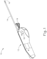
- FIG. 1 shows an exemplary equalization tube delivery device (PETDD) (10) that may be used in such procedures.
- PETDD equalization tube delivery device
- PETDD 10
- endoscope to provide visualization of the tympanic membrane (TM) during use of PETDD (10).
- a patient may receive local anesthesia at the tympanic membrane (TM) through a process of iontophoresis before PETDD (10) is actuated to deploy a PE tube.
- TM tympanic membrane
- iontophoresis may be provided in accordance with at least some of the teachings of U.S. Pub. No. 2010/0198135 ; and/or in accordance with at least some of the teachings of U.S.Patent No. 8, 192, 420 .
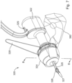
- PETDD (10) of this example includes a handpiece (12) and a cannula (14) extending distally from handpiece (12).
- Cannula (14) is sized for insertion in a patient's ear canal, such that the tip (16) of cannula may directly engage the patient's tympanic membrane (TM).
- the operator may depress button (18), which may trigger a firing sequence whereby PETDD (10) creates a myringotomy incision, dilates the myringotomy incision, and inserts a PE tube in the myringotomy incision nearly instantly.
- a pin (19) selectively locks button (18) to avoid premature firing of PETDD (10), such that the operator must remove pin (19) before intentionally firing PETDD (10).
- PETDD (10) may be constructed and operable in accordance with at least some of the teachings of U.S. Patent No. 8, 052, 693 ; U.S. Patent No. 8, 249, 700 ; U.S. Pub. No. 2011/0015645 ; and/or U.S. Pub. No. 2014/0276906 , entitled “Features to Improve and Sense Tympanic Membrane Apposition by Tympanostomy Tube Delivery Instrument," filed on even date herewith.
- Other suitable forms that PETDD (10) may take will be apparent to those of ordinary skill in the art in view of the teachings herein.
- a PE tube may be inserted in a tympanic membrane (TM) manually, such as by creating the myringotomy incision with a knife and inserting the PE tube using forceps, etc.
- TM tympanic membrane
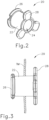
- FIGS. 2-3 show an exemplary PE tube (20) that may be delivered to the tympanic membrane (TM) using PETDD (10).
- PE tube (20) of this example comprises a cylindraceous body (22) that defines a passageway (24).
- a flange (26) is located at one end of body (22) while a set of petals (28) are located at the other end of body (22).
- PE tube (20) is formed of a resilient material that is biased to assume the rivet like configuration shown in FIGS. 2-3 .
- flange (26) and petals (28) may be flexed inwardly toward the longitudinal axis of body (22) to provide PE tube (20) with a cylindraceous configuration.
- flange (26) and petals (28) may be flexed such that their outer surfaces are at the same radial distance from the longitudinal axis as the outer perimeter of body (22). This may enable PE tube (200) to collapse to fit within cannula (14).
- petals (28) are located medially (i.e., on the middle ear side) while flange (26) is located laterally (i.e., on the outer ear side).
- PE tube (20) may also be configured in accordance with at least some of the teachings of U.S. Pat. No. 9,011,363, entitled “Tympanic Membrane Pressure Equalization Tube,” issued April 21, 2015 . and/or at least some of the teachings U.S. Pub. No. 2014/0276906 .
- Other suitable forms that PE tube (20) may take will be apparent to those of ordinary skill in the art in view of the teachings herein.
- PETDD (10) may be used in conjunction with an iontophoresis system, which may be used to anesthetize the patient's ear before PETDD (10) is inserted into the patient's ear canal to deliver PE tube (20) in the tympanic membrane (TM).
- iontophoresis may be provided in accordance with at least some of the teachings of U.S. Pub. No. 2010/0198135 , and/or in accordance with at least some of the teachings of U.S. Patent No. 8,192,420 .
- iontophoresis may be provided in accordance with any of the various teachings below.
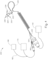
- FIG. 4 shows one merely illustrative iontophoresis system (200).
- Iontophoresis system (200) of this example comprises an earplug (220), fluid source (140), control unit (1.70), and ground pad (180).
- Earplug (220) is configured to be inserted into a patient's ear and remain there without needing a separate component like a headframe to hold it in place.
- a biocompatible adhesive may be used to assist in holding earplug (220) in place within a patient's ear canal.
- Earplug (220) includes a pair of gripping features (222) that are configured to be gripped and thereby serve as a handle during insertion of earplug (220) in a patient's ear.
- Earplug (220) also includes a pull-tab (228) that may be gripped and pulled to assist in removing earplug (220) from the patient's ear.
- a pull-tab (228) that may be gripped and pulled to assist in removing earplug (220) from the patient's ear.
- these features are mere examples, and any other suitable kinds of gripping features may be incorporated into earplug (220). While only one earplug (220) is shown, it should be understood that iontophoresis system (200) may have two earplugs (220) that may be used simultaneously.
- earplug (220) is configured and operable in accordance with at least some of the teachings of U.S. Pub. No. 2014/0102461, entitled “Adhesive Earplugs Useful for Sealing the Ear Canal," published April 17, 2014 .
- earplug (220) of the present example includes a flexible sealing element (224) and a distally projecting nozzle (226). Sealing element (224) is configured to provide a fluid tight seal against the patient's ear canal when earplug (220) is inserted in the patient's ear canal.
- a biocompatible pressure sensitive adhesive is applied to the outer surface of sealing element (224) to promote a fluid tight seal against the patient's ear canal.
- Nozzle (226) is positioned to project into the patient's ear canal when earplug (220) is inserted in the patient's ear canal, such that nozzle (226) is spaced lateral to the tympanic membrane (TM).
- Nozzle (226) has spray apertures (227) and is secured to the distal end of a semi-rigid post (225).
- Post (225) provides a path for fluid communication from conduit (230) to spray apertures (227). Spray apertures (227) are thus in fluid communication with fluid source (140) via post (225) and conduit (230).
- Sealing element (224) is secured to a rigid frame (223), which defines gripping features (222). Sealing element (224) and frame (223) also together define a working channel (221). Frame (223) defines a plurality of vent paths (229) in fluid communication with working channel (221). Vent paths (229) are configured to allow air to escape working channel (221) while working channel (221) fills with iontophoresis solution; yet are further configured prevent iontophoresis solution from escaping working channel (221) via vent paths (229) once working channel (221) is filled with iontophoresis solution.
- An iontophoresis electrode (252) in the form of a coil extends along at least part of the length of working channel (221).
- iontophoresis electrode (252) may have any other suitable configuration. Iontophoresis electrode (252) is coupled with control unit (170) via a cable (250) and is thereby operable to be activated with a positive voltage as described above. Thus, control unit (170) may activate iontophoresis electrode (252) to provide an electrorepulsive force to the iontophoresis solution ions delivered through apertures (227), to drive the anesthetic of the iontophoresis solution ions into the tympanic membrane (TM) for anesthetization of the tympanic membrane (TM) as described above.
- control unit (170) may activate iontophoresis electrode (252) to provide an electrorepulsive force to the iontophoresis solution ions delivered through apertures (227), to drive the anesthetic of the iontophoresis solution ions into the tympanic membrane (TM) for anesthetization of the tympanic membrane (TM) as described
- iontophoresis system (200) may be varied in numerous ways. Several examples of how iontophoresis system (200) may be varied will be described in greater detail below, while still other examples will be apparent to those of ordinary skill in the art in view of the teachings herein. While the various iontophoresis systems described herein have been mentioned in relation to PETDD (10) and PE tube (20) delivery, it should be understood that any of the iontophoresis systems described herein may be used before a manual delivery of a PE tube (20), such that the iontophoresis systems described herein do not necessarily need to be used in conjunction with a PETDD (10).
- iontophoresis systems may be used in various other clinical contexts, such that the iontophoresis systems described herein do not necessarily need to be used in the context of a PE tube (20) delivery or in other procedures in a patient's ear.
- the teachings herein may be readily applied to iontophoresis systems that are used in various other procedures and in various other parts of the human anatomy. Alternative systems and settings in which the teachings herein may be applied will be apparent to those of ordinary skill in the art.
- vent paths (229) of earplug (220) are configured to allow air to escape working channel (221) while working channel (221) and the patient's ear canal fills with iontophoresis solution.
- iontophoresis solution escapes through vent paths (229) and leaves a proximal portion of iontophoresis electrode (252) exposed to air. For instance, if the patient talks, coughs, swallows, cries, yawns, or otherwise moves their lower jaw, the motion associated with such activity may cause variation in the effective volume of the patient's ear canal.
- This variation of the effective volume of the patient's ear canal may in turn drive at least some iontophoresis solution through vent paths (229).
- the resulting exposure of even just a portion of iontophoresis electrode (252) to air may adversely affect the iontophoretic performance of earplug (220).
- the iontophoresis procedure may be completely interrupted until the physician injects more iontophoresis solution into earplug (220).
- vent paths (229) It may therefore be desirable to relocate and/or modify the structure associated with vent paths (229) in order to provide greater tolerance to variations in the effective volume of the patient's ear canal, to thereby reduce the risk of even a portion of iontophoresis electrode (252) being exposed to air during an iontophoresis procedure.
- the following example includes a variation of earplug (220) where the vent path is relocated.
- the following example is merely illustrative. Other suitable variations will be apparent to those of ordinary skill in the art in view of the teachings herein.
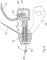
- FIG. 6 depicts another exemplary iontophoresis system (300) that may be used to anesthetize a patient's tympanic membrane (TM), such as before a inserting a PE tube (20) into the tympanic membrane (TM) as described above.
- Iontophoresis system (300) of this example is substantially similar to iontophoresis system (200) described above, except where otherwise noted herein.
- Iontophoresis system (300) comprises an earplug (320), which is substantially similar to earplug (220) described above, except earplug (320) is generally configured to provide improved management of fluid flow in response to volumetric changes in a patient's ear during an iontophoresis procedure.
- earplug (320) is in communication with fluid source (140) via a conduit (330) that is in the form of flexible tubing. Also like with earplug (220), earplug (320) is in communication with control unit (170) and ground pad (180) via a cable (350). Conduit (330) and cable (350) are coupled together along a shared length extending between a clip (340) and earplug (320). Clip (340) is operable to selectively secure the combination of conduit (330) and cable (350) to the patient's clothing and/or to any other suitable structure.
- Earplug (320) is configured to be inserted into a patient's ear and remain there without needing a separate component like a headframe to hold it in place. As will be described in greater detail below, a biocompatible pressure sensitive adhesive is be used to assist in holding earplug (320) in place within a patient's ear canal.
- Earplug (320) includes a gripping feature (322) that is configured to be gripped and thereby serve as a handle during insertion of earplug (320) in a patient's ear.
- Earplug (320) also includes a pull-tab (328) that may be gripped and pulled to assist in removing earplug (320) from the patient's ear.
- earplug (320) a feature that may be used in both of the patient's ears simultaneously or in a sequence.
- iontophoresis system (300) may have two earplugs (320) that may be used in both of the patient's ears simultaneously or in a sequence.
- earplug (320) of the present example includes a flexible sealing element (324) and a distally projecting nozzle (326).
- Sealing element (324) is configured to provide a fluid tight seal against the patient's ear canal when earplug (320) is inserted in the patient's ear canal.
- a pressure sensitive adhesive is applied to the outer surface of sealing element (324) to promote a fluid tight seal against the patient's ear canal.
- Nozzle (326) is positioned to project into the patient's ear canal when earplug (320) is inserted in the patient's ear canal, such that nozzle (326) is spaced lateral to the tympanic membrane (TM).
- Nozzle (326) has a plurality of spray apertures (327) and is secured to the distal end of a semi-rigid post (325).
- Post (325) defines a lumen providing a path for communication of fluid from conduit (330) to spray apertures (327).
- Spray apertures (327) are thus in fluid communication with fluid source (140) via post (325) and conduit (330).
- Sealing element (324) is secured to a rigid frame (323). Sealing element (324) and frame (323) together define a working channel (321), as will be described in greater detail below.
- Gripping feature (322) is fixedly secured to rigid frame (323). Gripping feature (322) and frame (323) cooperate to define a reservoir (370). Reservoir (370) is in fluid communication with working channel (321). Reservoir (370) extends laterally relative to a longitudinal axis defined by post (325). Thus, reservoir (370) and working channel (321) together form an L-shaped cavity. As will be described in greater detail below, this L-shaped cavity operates to maintain fluid contact with iontophoresis electrode (352) even when a patient's ear canal experiences volumetric changes throughout the iontophoresis procedure. Frame (323) also defines at least one vent path (329), which is also in fluid communication with reservoir (370).
- Vent path (329) is configured to allow air to escape reservoir (370) when reservoir (370) fills with iontophoresis solution, as will be described in greater detail below.
- vent path (329) is formed as a circular opening with a diameter of approximately 0.635 mm (0.025 inches).
- vent path (329) may have any other suitable size or configuration.
- An iontophoresis electrode (352) in the form of a coil extends along at least part of the length of working channel (321). It should be understood that iontophoresis electrode (352) may have any other suitable configuration. Iontophoresis electrode (352) is coupled with control unit (170) via cable (350) and is thereby operable to be activated with a positive voltage as described above.
- control unit (170) may activate iontophoresis electrode (352) to provide an electrorepulsive force to the iontophoresis solution ions delivered through apertures (327), to drive the anesthetic of the iontophoresis solution ions into the tympanic membrane (TM) for anesthetization of the tympanic membrane (TM) as described above.
- earplug (320) of the present example is configured to tolerate volumetric changes in a patient's ear during an iontophoresis procedure without letting iontophoresis electrode (352) become exposed to air.
- reservoir (370) of the present example is configured to effectively increase the volume of working channel (321), thereby providing a spacing between vent path (329) and iontophoresis electrode (352) that is greater than the spacing between vent paths (229) and iontophoresis electrode (252).
- reservoir (370) and working channel (321) provide a combined volume that is about three times that of working channel (221) described above.
- reservoir (370) and working channel (321) provide a combined volume that is between about two times and about four times that of working channel (221).
- reservoir (370) and working channel (321) may instead provide any other suitable combined volume in relation to the volume of working channel (221).
- earplug (320) of the present example is configured such that vent path (329) is repositioned for management of fluid flow in response to volumetric changes in a patient's ear canal.
- vent path (329) of the present example is positioned adjacent to reservoir (370) at the furthest lateral point of reservoir (370).
- vent path (329) directs fluid out of reservoir (370) such that any open space created by displaced fluid remains within reservoir (370).
- vent path (329) of the present example is shown as being integral with an opening for conduit (330), it should be understood that in other examples vent path (329) is a discrete opening in gripping feature (322), spaced away from the point at which conduit (330) enters gripping feature (322).
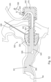
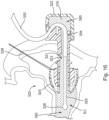
- FIGS. 9-15 show a merely illustrative use of earplug (320).
- earplug (320) is initially positioned outside of a patient's ear. At this stage, fluid has not yet been injected into earplug (320). The operator may begin the iontophoresis procedure by inserting sealing element (324) of earplug (320) into a patient's ear canal (EC). As can be seen in FIG. 10 , sealing element (324) is positioned to bear against the walls of the ear canal (EC), simultaneously securing earplug (320) and creating a fluid seal between sealing element (324) and the wall of the ear canal (EC).
- TM tympanic membrane
- 320 earplug
- a liner strip (380) as described below may be used to assist the operator in positioning earplug (320) in the ear canal (EC) without the operator's fingers getting stuck to the pressure sensitive adhesive on sealing element (324).
- earplug (320) is secured in the patient's ear canal (EC)
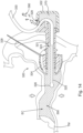
- the operator may begin administration of iontophoresis fluid (390) to the ear canal (EC) via conduit (330) and nozzle (326), as can be seen in FIG. 11 .
- fluid (390) is administered, the ear canal (EC), working channel (321) and reservoir (370) will fill with fluid (390); and the air displaced from the ear canal (EC), working channel (321) and reservoir (370) will flow out to the atmosphere through vent path (329).
- the operator may continue administering fluid (390) until fluid (390) is observed flowing out through vent path (329) as shown in FIG. 12 .
- earplug (320) is ready to activate iontophoresis electrode (352) to thereby provide an electrorepulsive force to the iontophoresis fluid ions.
- gripping feature (322) is transparent, enabling the operator to visually observe reservoir (370) filling with fluid (390). This may enable the operator to be more ready to cease injecting fluid (390) via conduit (330) when the level of fluid (390) reaches vent path (329).
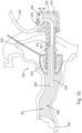
- a fluid delivery device such as a syringe from conduit (330). It should be understood that in some circumstances removal of such a device may result in some loss of fluid (390) from working channel (321). By way of example only, in some examples this may result in a loss of about 0.04 cc of fluid (390). As a result, an air pocket (392) of a corresponding volume may form adjacent to vent path (329) in reservoir (370), as shown in FIG. 13 .
- this air pocket (392) is substantially spaced away from iontophoresis electrode (352), such that iontophoresis electrode (352) remains fully submerged in fluid (390) with no meaningful risk of any portion of electrode (352) being exposed to air.
- the patient may talk, cough, swallow, cry, yawn, or otherwise move their lower jaw, and the motion associated with such activity may cause variation in the effective volume of the patient's ear canal (EC).
- volumetric changes may cause a pumping action, which will vary the level of fluid (390) in reservoir (370).
- this variation of the level of fluid (390) may displace fluid (390) out of vent path (329), as shown in FIG. 14 .
- fluid (390) is displaced out of vent path (329) the volume of fluid (390) disposed in the ear canal (EC), working channel (321), reservoir (370) is reduced by a corresponding amount.
- earplug (320) may be used in an inverted position (i.e., at a vertical orientation).
- the operator may wish to insert earplug (320) in a patient's ear while the patient's head is oriented toward the ground.
- reservoir (370) and vent path (329) may generally provide the same function as described above but with different positioning of the air in reservoir (370).
- an air bubble (394) is disposed within reservoir (370) away from vent path (329). Surface tension at the interface between the air bubble (394) and the fluid (390) keeps the air bubble (394) within reservoir (370) and away from the rest of working channel (321).
- a pressure sensitive adhesive may be provided on sealing element (324) in order to provide a more secure and fluid tight fit between sealing element (324) and the wall of the patient's ear canal (EC). It may be desirable to provide a feature that facilitates gripping and positioning of earplug (320) without the operator's fingers getting stuck to the pressure sensitive adhesive on sealing element (324).
- earplug (320) of the present example includes a liner strip (380).
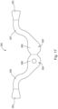
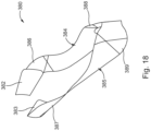
- FIGS. 17-19 show liner strip (380) in greater detail.
- liner strip (380) of the present example is constructed as a single generally flat part having a shape generally resembling an imperial moustache, or (when turned 180° from the view in FIG. 17 ) a handlebar mustache. At least a portion of liner strip (380) is coated with fluoro-silicone, providing a low-tack release surface that facilitates peeling of liner strip (380) away from the pressure sensitive adhesive on sealing element (324).
- Liner strip (380) itself comprises a generally flexible 0.02 mm (0.0009 inch) thick polyethylene terephthalate (PET) film.
- PET polyethylene terephthalate
- liner strip (380) may comprise a variety of other suitable materials having a range of thicknesses.
- liner strip (380) divides liner strip (380) into four discrete portions (382, 383, 384, 385).
- liner strip (380) may be folded along three fold lines (shown in broken lines in FIG. 17 ) to more readily define each portion (382, 383, 384, 385).
- liner strip (380) defines two attachment portions (382, 383) and two gripping portions (384, 385).
- attachment portions (382, 383) are folded in a reverse direction to define a surface suitable for attachment of liner strip (380) to opposing sides of sealing element (324).
- each attachment portion (382, 383) is also heat formed to define a slight curvature in each attachment portion (382, 383).
- each attachment portion (382, 383) is entirely optional and may be omitted in some examples. However, where used, the curvature of attachment portions (382, 383) corresponds to the curvature of flexible sealing element (324) of earplug (320) to promote full apposition between attachment portions (382, 383) and sealing element (324).
- each gripping portion (384, 385) extends proximally away from each respective attachment portion (382, 383).
- each gripping portion comprises a corresponding thin portion (386, 387) and thick portion (388, 389).
- Each thin portion (386, 387) curves laterally away from each attachment portion (382, 383) to orient each respective thick portion (388, 389) away from earplug (320). This feature permits thick portions (388, 389) to be used for grasping by a user to manipulate earplug (320) by grasping liner strip (380).
- liner strip (380) is placed on earplug (320) such that attachment portions (382, 383) are positioned about sealing element (324) at angular locations corresponding to the posterior and anterior walls of a patient's ear canal (EC). In some instances, this positioning corresponds to the areas of flexible sealing element (324) that will encounter the most resistance from a patient's ear canal (EC) during insertion of earplug (320). Such positioning may be desirable to ensure that the pressure sensitive adhesive on sealing element (324) fully engages the superior and inferior walls of the patient's ear canal (EC) before the pressure sensitive adhesive on sealing element (324) contacts the posterior and anterior walls of the patient's ear canal (EC).
- earplug (320) is inserted into the ear canal (EC) for enough for sealing element (324) to fully engage the posterior and anterior walls of the patient's ear canal (EC)
- the operator may peel away liner strip (380) to allow the pressure sensitive adhesive on sealing element (324) to contact the posterior and anterior walls of the patient's ear canal (EC).
- the pressure sensitive adhesive on sealing element (324) may contact the walls of the ear canal (EC) about the entire angular perimeter of sealing element (324).
- Liner strip (380) may then be disposed of.
- the pressure sensitive adhesive is provided about the entire angular perimeter of sealing element (324).
- attachment portions (382, 383) are together sized to contact approximately 40% of the surface of sealing element (324) that is coated with pressure sensitive adhesive.
- attachment portions (382, 383) may cover any other suitable portion of the surface of sealing element (324) that is coated with pressure sensitive adhesive. It should also be understood that pressure sensitive adhesive may be provided about only a portion of the angular perimeter of sealing element (324).
- earplug (320) may be configured such that pressure sensitive adhesive is only provided on the zones of sealing element (324) that will contact posterior and anterior walls of the patient's ear canal (EC); but not on the zones of sealing element (324) that will contact posterior and anterior walls of the patient's ear canal (EC).
- a lubricious material e.g., alcohol, etc.
- the lubricious material may be applied to the pressure sensitive adhesive on sealing element (324) to aid in insertion of sealing element (324) in the ear canal (EC); with the lubricious material being configured to evaporate or otherwise dissipate to enable the pressure sensitive adhesive to adhere to the walls of the ear canal (EC) shortly after sealing element (324) is inserted in the ear canal (EC).
- a lubricious material e.g., alcohol, etc.
- any of the examples described herein may include various other features in addition to or in lieu of those described above.
- any of the devices herein may also include one or more of the various features disclosed in any of the various references.
- any one or more of the teachings, expressions, embodiments, examples, etc. described herein may be combined with any one or more of the other teachings, expressions, embodiments, examples, etc. that are described herein.
- the above-described teachings, expressions, embodiments, examples, etc. should therefore not be viewed in isolation relative to each other.
- Various suitable ways in which the teachings herein may be combined will be readily apparent to those of ordinary skill in the art in view of the teachings herein. Such modifications and variations are intended to be included within the scope of the claims.
- Versions described above may be designed to be disposed of after a single use, or they can be designed to be used multiple times. Versions may, in either or both cases, be reconditioned for reuse after at least one use. Reconditioning may include any combination of the steps of disassembly of the device, followed by cleaning or replacement of particular pieces, and subsequent reassembly. In particular, some versions of the device may be disassembled, and any number of the particular pieces or parts of the device may be selectively replaced or removed in any combination. Upon cleaning and/or replacement of particular parts, some versions of the device may be reassembled for subsequent use either at a reconditioning facility, or by a user immediately prior to a procedure.
- reconditioning of a device may utilize a variety of techniques for disassembly, cleaning/replacement, and reassembly. Use of such techniques, and the resulting reconditioned device, are all within the scope of the present application.
- versions described herein may be sterilized before and/or after a procedure.
- the device is placed in a closed and sealed container, such as a plastic or TYVEK bag.
- the container and device may then be placed in a field of radiation that can penetrate the container, such as gamma radiation, x-rays, or high-energy electrons.
- the radiation may kill bacteria on the device and in the container.
- the sterilized device may then be stored in the sterile container for later use.
- a device may also be sterilized using any other technique known in the art, including but not limited to beta or gamma radiation, ethylene oxide, or steam.
- inventive embodiments are presented by way of example only and that, within the scope of the appended claims and equivalents thereto; inventive embodiments may be practiced otherwise than as specifically described and claimed.
- inventive embodiments of the present disclosure are directed to each individual feature, system, article, material, kit, and/or method described herein.
- inventive concepts may be embodied as one or more methods, of which an example has been provided.
- the acts performed as part of the method may be ordered in any suitable way. Accordingly, embodiments may be constructed in which acts are performed in an order different than illustrated, which may include performing some acts simultaneously, even though shown as sequential acts in illustrative embodiments.
- a reference to "A and/or B", when used in conjunction with open-ended language such as “comprising” can refer, in one embodiment, to A only (optionally including elements other than B); in another embodiment, to B only (optionally including elements other than A); in yet another embodiment, to both A and B (optionally including other elements); etc.
- the phrase "at least one,” in reference to a list of one or more elements, should be understood to mean at least one element selected from any one or more of the elements in the list of elements, but not necessarily including at least one of each and every element specifically listed within the list of elements and not excluding any combinations of elements in the list of elements.
- This definition also allows that elements may optionally be present other than the elements specifically identified within the list of elements to which the phrase "at least one" refers, whether related or unrelated to those elements specifically identified.
- At least one of A and B can refer, in one embodiment, to at least one, optionally including more than one, A, with no B present (and optionally including elements other than B); in another embodiment, to at least one, optionally including more than one, B, with no A present (and optionally including elements other than A); in yet another embodiment, to at least one, optionally including more than one, A, and at least one, optionally including more than one, B (and optionally including other elements); etc.
Landscapes
- Health & Medical Sciences (AREA)
- Life Sciences & Earth Sciences (AREA)
- Engineering & Computer Science (AREA)
- Biomedical Technology (AREA)
- Animal Behavior & Ethology (AREA)
- General Health & Medical Sciences (AREA)
- Public Health (AREA)
- Veterinary Medicine (AREA)
- Nuclear Medicine, Radiotherapy & Molecular Imaging (AREA)
- Radiology & Medical Imaging (AREA)
- Heart & Thoracic Surgery (AREA)
- Acoustics & Sound (AREA)
- Physics & Mathematics (AREA)
- Biophysics (AREA)
- Otolaryngology (AREA)
- Psychology (AREA)
- Vascular Medicine (AREA)
- Cardiology (AREA)
- Bioinformatics & Cheminformatics (AREA)
- Anesthesiology (AREA)
- Hematology (AREA)
- Surgery (AREA)
- Electrotherapy Devices (AREA)
- Infusion, Injection, And Reservoir Apparatuses (AREA)
Applications Claiming Priority (2)
| Application Number | Priority Date | Filing Date | Title |
|---|---|---|---|
| US14/800,869 US10016304B2 (en) | 2015-07-16 | 2015-07-16 | Earplug assembly for iontophoresis system |
| PCT/US2016/042577 WO2017011777A1 (en) | 2015-07-16 | 2016-07-15 | Earplug assembly for iontophoresis system |
Publications (2)
| Publication Number | Publication Date |
|---|---|
| EP3322390A1 EP3322390A1 (en) | 2018-05-23 |
| EP3322390B1 true EP3322390B1 (en) | 2024-06-12 |
Family
ID=56682243
Family Applications (1)
| Application Number | Title | Priority Date | Filing Date |
|---|---|---|---|
| EP16750545.2A Active EP3322390B1 (en) | 2015-07-16 | 2016-07-15 | Earplug for iontophoresis system |
Country Status (7)
Families Citing this family (16)
| Publication number | Priority date | Publication date | Assignee | Title |
|---|---|---|---|---|
| US8249700B2 (en) | 2007-04-19 | 2012-08-21 | Acclarent, Inc. | System and method for the simultaneous bilateral integrated tympanic drug delivery and guided treatment of target tissues within the ears |
| US8192420B2 (en) | 2007-12-20 | 2012-06-05 | Acclarent, Inc. | Iontophoresis methods |
| US8840602B2 (en) | 2008-07-31 | 2014-09-23 | Acclarent, Inc. | Systems and methods for anesthetizing ear tissue |
| RU2014106868A (ru) | 2011-07-25 | 2015-08-27 | Аккларент, Инк. | Персонализируемая система и способ для анестезирования барабанной перепонки |
| US9364648B2 (en) | 2012-05-30 | 2016-06-14 | Tusker Medical, Inc. | Adhesive earplugs useful for sealing the ear canal |
| US10130808B2 (en) | 2013-03-14 | 2018-11-20 | Tusker Medical, Inc. | System and method for providing iontophoresis at tympanic membrane |
| US10016304B2 (en) | 2015-07-16 | 2018-07-10 | Tusker Medical, Inc. | Earplug assembly for iontophoresis system |
| ES3009062T3 (en) * | 2017-03-22 | 2025-03-25 | Magneto Thrombectomy Solutions Ltd | Thrombectomy using both electrostatic and suction forces |
| US12029475B2 (en) | 2017-03-22 | 2024-07-09 | Magneto Thrombectomy Solutions Ltd. | Thrombectomy using both electrostatic and suction forces |
| US11660105B2 (en) | 2017-11-23 | 2023-05-30 | Magneto Thrombectomy Solutions Ltd. | Tubular thrombectomy devices |
| AU2019209321B2 (en) * | 2018-01-16 | 2024-08-22 | Tusker Medical, Inc. | Earset assembly for providing iontophoresis including valve |
| JP7273830B2 (ja) | 2018-01-16 | 2023-05-15 | タスカー メディカル,インコーポレイテッド | 耳下手術のための可視化デバイス |
| CN109011091B (zh) * | 2018-07-16 | 2021-07-23 | 日照市中医医院 | 一种手术室用均压防护型氧气湿化瓶 |
| US12251531B2 (en) * | 2019-05-13 | 2025-03-18 | Hogne Ab | Plug for insertion into the nose or ear of a subject and method for administering a fluid therapeutic agent using said plug |
| EP4221652A1 (en) * | 2020-09-29 | 2023-08-09 | Smith&Nephew, Inc. | Systems and methods for delivering an anesthetizing solution into the ear canal |
| CN119157693B (zh) * | 2024-11-21 | 2025-02-28 | 南昌大学第二附属医院 | 一种耳道异物取物器 |
Family Cites Families (159)
| Publication number | Priority date | Publication date | Assignee | Title |
|---|---|---|---|---|
| US858673A (en) | 1906-08-30 | 1907-07-02 | Charles R Roswell | Device adapted for curing deafness. |
| US1920006A (en) | 1932-07-26 | 1933-07-25 | Edward A Arnim Jr | Prostatic catheter |
| US2458884A (en) | 1946-01-03 | 1949-01-11 | Volkmann John | Ear protector valve |
| US3052693A (en) | 1959-03-13 | 1962-09-04 | Schering Ag | Steroid alkyl ethers and process therefor |
| CH538277A (fr) | 1970-09-04 | 1973-06-30 | Micromedic Systems Inc | Dispositif pour prise de sang percutanée |
| US3897786A (en) | 1971-02-05 | 1975-08-05 | Richards Mfg Co | Disposable myringotomy apparatus |
| US3948271A (en) | 1972-11-07 | 1976-04-06 | Taichiro Akiyama | Drain for the eardrum and apparatus for introducing the same |
| US3888258A (en) | 1972-11-07 | 1975-06-10 | Taichiro Akiyama | Drain for the eardrum and apparatus for introducing the same |
| US3991755A (en) | 1973-07-27 | 1976-11-16 | Medicon, Inc. | Iontophoresis apparatus for applying local anesthetics |
| US3913584A (en) | 1974-06-28 | 1975-10-21 | Xomox Corp | Combination myringotomy scalpel, aspirator and otological vent tube inserter |
| JPS5347192A (en) | 1976-10-13 | 1978-04-27 | Matsushita Electric Ind Co Ltd | Device for introducing fluorine ion to tooth |
| US4206756A (en) | 1977-03-23 | 1980-06-10 | Murray Grossan | Jet ear irrigation system |
| US4406282A (en) | 1981-02-20 | 1983-09-27 | Parker Bruce W | Earplug for an underwater diver |
| US4406982A (en) | 1981-11-12 | 1983-09-27 | T. & L. Enterprises, Inc. | DC Motor control circuit |
| US4435915A (en) | 1982-01-20 | 1984-03-13 | Marvin Glass & Associates | Hanging doll house structure |
| US4601294A (en) | 1982-01-25 | 1986-07-22 | Minnesota Mining And Manufacturing Company | Ear canal electrode |
| DE3215423C2 (de) | 1982-04-24 | 1986-01-23 | W. Schlafhorst & Co, 4050 Mönchengladbach | Druckgasspleißkopf |
| FR2526656A1 (fr) | 1982-05-12 | 1983-11-18 | Dumas Yves | Laveur de conduits auditifs a eau collectee et recyclee |
| US4468218A (en) | 1982-09-24 | 1984-08-28 | Armstrong Beverly W | Ventilation tube for the middle ear and method of implanting same |
| JPS59129815A (ja) | 1983-01-18 | 1984-07-26 | Sumitomo Electric Ind Ltd | 光電素子のスリ−ブ内組立方法及びその装置 |
| JPS59129815U (ja) | 1983-02-16 | 1984-08-31 | 小田原 雅文 | 耳覆い |
| US4552137A (en) | 1983-08-16 | 1985-11-12 | Strauss Richard H | Earplugs |
| US4564009A (en) | 1983-08-24 | 1986-01-14 | Mine Safety Appliances Company | Universal ear plug |
| CA1292285C (en) | 1985-08-21 | 1991-11-19 | Paul H. Stypulkowski | External ear canal electrode to be placed proximate the tympanic membrane and method of stimulating/recording utilizing external ear canal electrode placed proximate the tympanic membrane |
| US4964850A (en) | 1986-05-07 | 1990-10-23 | Vincent Bouton | Method for treating trans-nasal sinus afflictions using a double t-shaped trans-nasal aerator |
| US4712537A (en) | 1986-08-13 | 1987-12-15 | Pender Daniel J | Apparatus for treating recurrent ear infections |
| SE8703694L (sv) | 1987-09-25 | 1989-03-26 | Barbara Densert | Saett att lufta mellanoerat medelst en insaettbar ventilationstub, ventilationstub foer utfoerande av saettet jaemte anvaendning av en dylik ventilationstub |
| US5261903A (en) | 1988-04-11 | 1993-11-16 | M.D. Inc. | Composite anesthetic article and method of use |
| DK45889D0 (da) | 1989-02-01 | 1989-02-01 | Medicoteknisk Inst | Fremgangsmaade til hoereapparattilpasning |
| US5135478A (en) | 1989-05-10 | 1992-08-04 | Drug Delivery Systems Inc. | Multi-signal electrical transdermal drug applicator |
| US5026378A (en) | 1989-11-09 | 1991-06-25 | Goldsmith Iii Manning M | Punch myringotomy system and method |
| US5053040A (en) | 1989-11-09 | 1991-10-01 | Goldsmith Iii Manning M | Method of performing a myringotomy |
| US4968296A (en) | 1989-12-20 | 1990-11-06 | Robert Ritch | Transscleral drainage implant device for the treatment of glaucoma |
| US5047007A (en) | 1989-12-22 | 1991-09-10 | Medtronic, Inc. | Method and apparatus for pulsed iontophoretic drug delivery |
| US5160316A (en) | 1990-09-10 | 1992-11-03 | Henley Julian L | Iontophoretic drug delivery apparatus |
| US5176654B1 (en) | 1990-12-07 | 1999-12-07 | Simeon B Schreiber | Method and apparatus for otologic administration of medicament |
| US5107861A (en) | 1990-12-10 | 1992-04-28 | Lillian Narboni | Safe ear clean button and protection with attachment device |
| US5254081A (en) | 1991-02-01 | 1993-10-19 | Empi, Inc. | Multiple site drug iontophoresis electronic device and method |
| CN2087067U (zh) | 1991-04-03 | 1991-10-23 | 胡广艾 | 中耳炎治疗仪 |
| US6183469B1 (en) | 1997-08-27 | 2001-02-06 | Arthrocare Corporation | Electrosurgical systems and methods for the removal of pacemaker leads |
| US5254120A (en) | 1992-02-11 | 1993-10-19 | Cinberg James Z | Myringotomy ventilliation tube, method, applicator and kit |
| US5466239A (en) | 1992-07-28 | 1995-11-14 | Cinberg; James Z. | Myringotomy ventilation tube and associated method |
| US5466939A (en) | 1992-09-24 | 1995-11-14 | Shimadzu Corporation | Nuclear medicine imaging apparatus |
| USD352780S (en) | 1993-04-19 | 1994-11-22 | Valleylab Inc. | Combined suction, irrigation and electrosurgical handle |
| US5550019A (en) | 1993-05-26 | 1996-08-27 | La Jolla Cancer Research Foundation | Methods of identifying compounds which alter apoptosis |
| JPH0779499A (ja) | 1993-09-08 | 1995-03-20 | Sony Corp | 補聴器 |
| US5496329A (en) | 1993-09-08 | 1996-03-05 | Alpha Surgical, Inc. | Method and apparatus for implanting a medical ventilation tube |
| US5421818A (en) | 1993-10-18 | 1995-06-06 | Inner Ear Medical Delivery Systems, Inc. | Multi-functional inner ear treatment and diagnostic system |
| JP2807859B2 (ja) | 1993-10-21 | 1998-10-08 | 永島医科器械株式会社 | 鼓膜麻酔器兼治療器 |
| US5735817A (en) | 1995-05-19 | 1998-04-07 | Shantha; T. R. | Apparatus for transsphenoidal stimulation of the pituitary gland and adjoining brain structures |
| US6475138B1 (en) | 1995-07-12 | 2002-11-05 | Laser Industries Ltd. | Apparatus and method as preparation for performing a myringotomy in a child's ear without the need for anaesthesia |
| US5707383A (en) | 1995-10-05 | 1998-01-13 | Xomed Surgical Products, Inc. | Method of removing soft tissue in the middle ear |
| USD378611S (en) | 1995-10-19 | 1997-03-25 | Ethicon Endo-Surgery, Inc. | Electrosurgical instrument |
| US6045578A (en) | 1995-11-28 | 2000-04-04 | Queensland University Of Technology | Optical treatment method |
| US5643280A (en) | 1995-12-07 | 1997-07-01 | The Anspach Effort, Inc. | Integral myringotomy tube and inserter |
| US5674196A (en) | 1996-01-05 | 1997-10-07 | Donaldson; John | Device for introducing medical fluid into the human ear |
| US5893828A (en) | 1996-05-02 | 1999-04-13 | Uram; Martin | Contact laser surgical endoscope and associated myringotomy procedure |
| DE19618585A1 (de) | 1996-05-09 | 1997-11-13 | Michael Glimmann | Ohrstöpsel mit Pumpe zur Unterdruckerzeugung im Gehörgang |
| USD387863S (en) | 1996-07-22 | 1997-12-16 | Microvena Corporation | Medical device delivery handle |
| USD420741S (en) | 1996-08-20 | 2000-02-15 | Ethicon Endo-Surgery, Inc. | Handle for an electrosurgical instrument |
| US5810848A (en) | 1996-08-21 | 1998-09-22 | Hayhurst; John O. | Suturing system |
| US5910150A (en) | 1996-12-02 | 1999-06-08 | Angiotrax, Inc. | Apparatus for performing surgery |
| US6045528A (en) | 1997-06-13 | 2000-04-04 | Intraear, Inc. | Inner ear fluid transfer and diagnostic system |
| US5804957A (en) | 1997-08-13 | 1998-09-08 | Analog Devices, Inc. | Constant current supply system for a variable resistance load |
| US6206888B1 (en) | 1997-10-01 | 2001-03-27 | Scimed Life Systems, Inc. | Stent delivery system using shape memory retraction |
| US6295469B1 (en) | 1997-11-14 | 2001-09-25 | Alza Corporation | Formulation for electrically assisted delivery of lidocaine and epinephrine |
| US5979072A (en) | 1998-02-18 | 1999-11-09 | Collins, Ii; Hamilton P. | External auditory canal drying apparatus |
| US6148821A (en) | 1998-04-29 | 2000-11-21 | Cabot Safety Intermediate Corporation | Selective nonlinear attenuating earplug |
| US6137889A (en) | 1998-05-27 | 2000-10-24 | Insonus Medical, Inc. | Direct tympanic membrane excitation via vibrationally conductive assembly |
| US6200280B1 (en) | 1998-05-29 | 2001-03-13 | Theracardia, Inc. | Cardiac massage apparatus and method |
| USD418223S (en) | 1998-06-05 | 1999-12-28 | Eclipse Surgical Technologies, Inc. | Hand piece for surgical and biopsy procedures |
| US6440102B1 (en) | 1998-07-23 | 2002-08-27 | Durect Corporation | Fluid transfer and diagnostic system for treating the inner ear |
| US6358231B1 (en) | 1998-08-24 | 2002-03-19 | Biopolymer, Inc. | Transdermal anesthetizing solution and method and apparatus for anesthetizing the ear canal and tympanic membrane |
| WO2000018330A1 (en) | 1998-09-30 | 2000-04-06 | Impra, Inc. | Delivery mechanism for implantable stent |
| US6148232A (en) | 1998-11-09 | 2000-11-14 | Elecsys Ltd. | Transdermal drug delivery and analyte extraction |
| USD424197S (en) | 1999-02-12 | 2000-05-02 | Thermolase Corporation | Laser handpiece housing |
| EP1165161B1 (en) | 1999-03-03 | 2005-11-02 | UAB Research Foundation | Direct central nervous system catheter and temperature control system |
| US6553253B1 (en) | 1999-03-12 | 2003-04-22 | Biophoretic Therapeutic Systems, Llc | Method and system for electrokinetic delivery of a substance |
| US7127285B2 (en) | 1999-03-12 | 2006-10-24 | Transport Pharmaceuticals Inc. | Systems and methods for electrokinetic delivery of a substance |
| US6059803A (en) | 1999-06-01 | 2000-05-09 | Spilman; Daniel A. | Ear vacuum |
| US6640121B1 (en) | 1999-08-10 | 2003-10-28 | The University Of Miami | Otic microprobe for neuro-cochlear monitoring |
| USD426135S (en) | 1999-09-02 | 2000-06-06 | Shu-Chen Lee | Tool handle |
| US6245077B1 (en) | 2000-01-21 | 2001-06-12 | Exmoor Plastics Ltd. | Universal myringotomy tube/aural grommet inserter and methods |
| US6347246B1 (en) | 2000-02-03 | 2002-02-12 | Axelgaard Manufacturing Company, Ltd. | Electrotransport adhesive for iontophoresis device |
| EP1259285A1 (en) | 2000-02-18 | 2002-11-27 | University of Utah | Methods for delivering agents using alternating current |
| CN2409940Y (zh) | 2000-02-25 | 2000-12-13 | 陈向东 | 耳塞式激光光纤固定架 |
| USD450843S1 (en) | 2000-05-30 | 2001-11-20 | Boston Scientific Corporation | Thrombectomy handpiece |
| DE10041725B4 (de) | 2000-08-25 | 2004-04-29 | Phonak Ag | Gerät zur elektromechanischen Stimulation und Prüfung des Gehörs |
| US6522827B1 (en) | 2000-10-11 | 2003-02-18 | Trimedyne, Inc. | Laser devices for performing a myringotomy |
| DE20020252U1 (de) | 2000-11-29 | 2002-04-11 | Maslanka, Herbert, 78532 Tuttlingen | Sprühkatheter |
| US20020069883A1 (en) | 2000-12-08 | 2002-06-13 | Aviv Hirchenbain | Device for active regulation of pressure on outer ear |
| DK174538B1 (da) | 2001-01-26 | 2003-05-19 | Coloplast As | Renseindretning |
| US7137975B2 (en) | 2001-02-13 | 2006-11-21 | Aciont, Inc. | Method for increasing the battery life of an alternating current iontophoresis device using a barrier-modifying agent |
| US6520939B2 (en) | 2001-02-13 | 2003-02-18 | Scimed Life Systems, Inc. | Hemostasis valve |
| US20020138091A1 (en) | 2001-03-23 | 2002-09-26 | Devonrex, Inc. | Micro-invasive nucleotomy device and method |
| US6770080B2 (en) | 2001-04-26 | 2004-08-03 | Fenestra Medical, Inc. | Mechanically registered videoscopic myringotomy/tympanostomy tube placement system |
| US6682558B2 (en) | 2001-05-10 | 2004-01-27 | 3F Therapeutics, Inc. | Delivery system for a stentless valve bioprosthesis |
| US7344507B2 (en) | 2002-04-19 | 2008-03-18 | Pelikan Technologies, Inc. | Method and apparatus for lancet actuation |
| US7115136B2 (en) | 2001-06-20 | 2006-10-03 | Park Medical Llc | Anastomotic device |
| US7094228B2 (en) | 2001-07-31 | 2006-08-22 | Zars, Inc. | Methods and formulations for photodynamic therapy |
| US6648873B2 (en) | 2001-09-21 | 2003-11-18 | Durect Corp. | Aural catheter system including anchor balloon and balloon inflation device |
| US6645173B1 (en) | 2002-03-29 | 2003-11-11 | Barbara Liebowitz | Dripless eardrop applicator |
| US7563232B2 (en) | 2002-04-19 | 2009-07-21 | Pelikan Technologies, Inc. | Method and apparatus for penetrating tissue |
| EP2386758A1 (en) | 2002-10-09 | 2011-11-16 | Abbott Diabetes Care Inc. | A method of pumping a predetermined dose of a medical fluid |
| US7381210B2 (en) | 2003-03-14 | 2008-06-03 | Edwards Lifesciences Corporation | Mitral valve repair system and method for use |
| CA2424347C (en) | 2003-04-02 | 2006-10-10 | Herman Chiang | Ear plug |
| DK1638638T3 (da) | 2003-06-20 | 2009-11-23 | Allergan Inc | Tovejsslidsventil |
| US7697706B2 (en) | 2003-11-03 | 2010-04-13 | 3M Innovative Properties Company | Low sound attenuating hearing protection device |
| US7898821B2 (en) | 2003-12-10 | 2011-03-01 | Nokia Corporation | Apparatus and arrangement for shielding a light emitting diode against electrostatic discharge |
| US7794436B2 (en) | 2004-01-13 | 2010-09-14 | Lloyd Jay Pinel | Controlled gastric bolus feeding device |
| US7351246B2 (en) | 2004-01-20 | 2008-04-01 | Epley John M | Minimally invasive, sustained, intra-tympanic drug delivery system |
| US20060177080A1 (en) | 2005-01-25 | 2006-08-10 | Smith Richard C | Earpiece with flanged extension |
| US20050203550A1 (en) | 2004-03-11 | 2005-09-15 | Laufer Michael D. | Surgical fastener |
| US7677734B2 (en) | 2004-04-09 | 2010-03-16 | Arthur Wallace | Audiovisual distraction in patients undergoing surgery with regional anesthesia |
| US7654997B2 (en) | 2004-04-21 | 2010-02-02 | Acclarent, Inc. | Devices, systems and methods for diagnosing and treating sinusitus and other disorders of the ears, nose and/or throat |
| US7778434B2 (en) | 2004-05-28 | 2010-08-17 | General Hearing Instrument, Inc. | Self forming in-the-ear hearing aid with conical stent |
| DE102004030069B3 (de) | 2004-06-23 | 2005-12-22 | Drägerwerk AG | Atemmaske mit einer adhäsiven Dichtung |
| USD535027S1 (en) | 2004-10-06 | 2007-01-09 | Sherwood Services Ag | Low profile vessel sealing and cutting mechanism |
| US7402172B2 (en) | 2004-10-13 | 2008-07-22 | Boston Scientific Scimed, Inc. | Intraluminal therapeutic patch |
| US8252045B2 (en) | 2005-03-12 | 2012-08-28 | Saint Louis University | Drug delivery from electroactive molecularly imprinted polymer |
| WO2006119512A2 (en) | 2005-05-05 | 2006-11-09 | University Of Virginia Patent Foundation | Surgical tool and insertion device for tube placement |
| US20080051804A1 (en) | 2005-05-05 | 2008-02-28 | Cottler Shayn P | Tube, stent and collar insertion device |
| US20070003096A1 (en) | 2005-06-29 | 2007-01-04 | Daehwi Nam | Microphone and headphone assembly for the ear |
| US8409175B2 (en) | 2005-07-20 | 2013-04-02 | Woojin Lee | Surgical instrument guide device |
| CA2619925A1 (en) | 2005-09-07 | 2007-03-15 | Tyco Healthcare Group Lp | Wound dressing with vacuum reservoir |
| US20070078372A1 (en) | 2005-09-30 | 2007-04-05 | Vyteris, Inc. | Iontophoresis Drug Delivery Formulation Providing Acceptable Sensation and Dermal Anesthesia |
| US8518098B2 (en) | 2006-02-21 | 2013-08-27 | Cook Medical Technologies Llc | Split sheath deployment system |
| USD598543S1 (en) | 2006-06-13 | 2009-08-18 | Angiomed Gmbh & Co. Medizintechnik Kg | Handle for a medical delivery device |
| US20080011308A1 (en) | 2006-07-12 | 2008-01-17 | Thomas Walter Fleming | Reverse fitting earplug |
| CA2661877A1 (en) | 2006-09-05 | 2008-03-13 | Tti Ellebeau, Inc. | Non-destructive systems, devices, and methods for evaluating iontophoresis drug delivery devices |
| US20080065002A1 (en) | 2006-09-07 | 2008-03-13 | Neurosystec Corporation | Catheter for Localized Drug Delivery and/or Electrical Stimulation |
| US8027481B2 (en) | 2006-11-06 | 2011-09-27 | Terry Beard | Personal hearing control system and method |
| DE102006060927A1 (de) | 2006-12-20 | 2008-06-26 | Atmel Germany Gmbh | Meldeeinrichtung und Verfahren zum Programmieren einer Meldeeinrichtung |
| US8249700B2 (en) | 2007-04-19 | 2012-08-21 | Acclarent, Inc. | System and method for the simultaneous bilateral integrated tympanic drug delivery and guided treatment of target tissues within the ears |
| USD595410S1 (en) | 2007-05-07 | 2009-06-30 | Derma Dream Ltd. | Demabrasion applicator |
| GB2450931A (en) | 2007-07-13 | 2009-01-14 | Mark Andrew Palmer | Ear-muffs incorporating a pump to control pressure within the ears |
| US8192420B2 (en) | 2007-12-20 | 2012-06-05 | Acclarent, Inc. | Iontophoresis methods |
| WO2009100383A2 (en) | 2008-02-07 | 2009-08-13 | University Of Washington | Circumferential aerosol device |
| CA2716040C (en) | 2008-02-20 | 2016-11-08 | Preceptis Medical, Llc | Ventilation device and insertion system therefor |
| JP5434905B2 (ja) | 2008-03-04 | 2014-03-05 | 日本電気株式会社 | 利得可変増幅器 |
| US7942852B2 (en) | 2008-04-23 | 2011-05-17 | Medtronic Vascular, Inc. | Aspiration catheter having an internal vacuum accumulator |
| US8840602B2 (en) | 2008-07-31 | 2014-09-23 | Acclarent, Inc. | Systems and methods for anesthetizing ear tissue |
| US8452392B2 (en) * | 2008-07-31 | 2013-05-28 | Acclarent, Inc. | Systems and methods for anesthetizing ear tissue |
| US8498425B2 (en) | 2008-08-13 | 2013-07-30 | Onvocal Inc | Wearable headset with self-contained vocal feedback and vocal command |
| US20100061581A1 (en) | 2008-09-09 | 2010-03-11 | Creative Technology Ltd | Sound producing device |
| US8291911B2 (en) | 2009-05-27 | 2012-10-23 | 3M Innovative Properties Company | Earplug |
| RU2543856C2 (ru) | 2009-07-15 | 2015-03-10 | Аккларент, Инк. | Система доставки трубки для выравнивания давления на барабанную перепонку |
| USD622849S1 (en) | 2009-07-21 | 2010-08-31 | Synvasive Technology, Inc. | Surgical saw device |
| USD622842S1 (en) | 2009-08-06 | 2010-08-31 | Given Imaging Ltd. | Implantable monitor delivery device handle |
| US8594356B2 (en) | 2010-04-29 | 2013-11-26 | Cochlear Limited | Bone conduction device having limited range of travel |
| US20120109070A1 (en) | 2010-10-28 | 2012-05-03 | Centurion Medical Products Corporation | Catheter securement device to secure silicone winged piccs |
| RU2014106868A (ru) | 2011-07-25 | 2015-08-27 | Аккларент, Инк. | Персонализируемая система и способ для анестезирования барабанной перепонки |
| US9138165B2 (en) | 2012-02-22 | 2015-09-22 | Veran Medical Technologies, Inc. | Systems, methods and devices for forming respiratory-gated point cloud for four dimensional soft tissue navigation |
| US9011363B2 (en) | 2012-04-10 | 2015-04-21 | Acclarent, Inc. | Tympanic membrane pressure equalization tube |
| US9364648B2 (en) | 2012-05-30 | 2016-06-14 | Tusker Medical, Inc. | Adhesive earplugs useful for sealing the ear canal |
| US10130808B2 (en) | 2013-03-14 | 2018-11-20 | Tusker Medical, Inc. | System and method for providing iontophoresis at tympanic membrane |
| US9320652B2 (en) | 2013-03-14 | 2016-04-26 | Tusker Medical, Inc. | Features to improve and sense tympanic membrane apposition by tympanostomy tube delivery instrument |
| CN203898546U (zh) * | 2014-06-21 | 2014-10-29 | 钟庄龙 | 一种鼓膜切开吸引刀 |
| US10016304B2 (en) | 2015-07-16 | 2018-07-10 | Tusker Medical, Inc. | Earplug assembly for iontophoresis system |
-
2015
- 2015-07-16 US US14/800,869 patent/US10016304B2/en active Active
-
2016
- 2016-07-15 CA CA2992523A patent/CA2992523A1/en not_active Abandoned
- 2016-07-15 EP EP16750545.2A patent/EP3322390B1/en active Active
- 2016-07-15 CN CN201680049554.8A patent/CN107920921B/zh active Active
- 2016-07-15 JP JP2018500895A patent/JP6849652B2/ja active Active
- 2016-07-15 AU AU2016291677A patent/AU2016291677B2/en active Active
- 2016-07-15 WO PCT/US2016/042577 patent/WO2017011777A1/en active Application Filing
-
2018
- 2018-07-06 US US16/028,687 patent/US10842676B2/en active Active
-
2020
- 2020-10-05 US US17/063,115 patent/US11696854B2/en active Active
Also Published As
| Publication number | Publication date |
|---|---|
| US10016304B2 (en) | 2018-07-10 |
| AU2016291677A1 (en) | 2018-02-01 |
| US11696854B2 (en) | 2023-07-11 |
| JP6849652B2 (ja) | 2021-03-24 |
| AU2016291677B2 (en) | 2021-07-15 |
| US20210015673A1 (en) | 2021-01-21 |
| US10842676B2 (en) | 2020-11-24 |
| WO2017011777A1 (en) | 2017-01-19 |
| US20180325737A1 (en) | 2018-11-15 |
| CA2992523A1 (en) | 2017-01-19 |
| US20170014272A1 (en) | 2017-01-19 |
| CN107920921A (zh) | 2018-04-17 |
| EP3322390A1 (en) | 2018-05-23 |
| JP2018519945A (ja) | 2018-07-26 |
| CN107920921B (zh) | 2021-04-13 |
Similar Documents
| Publication | Publication Date | Title |
|---|---|---|
| EP3322390B1 (en) | Earplug for iontophoresis system | |
| US11337852B2 (en) | Therapeutic agent delivery device | |
| US11554042B2 (en) | Method and apparatus for subretinal administration of therapeutic agent | |
| ES2821389T3 (es) | Aparato de guía para la introducción tangencial en el espacio supracoroideo | |
| KR102205295B1 (ko) | 곡침을 통해 치료제를 망막하 투여하기 위한 장치 | |
| ES2961233T3 (es) | Dispositivo de administración de agente terapéutico con cánula y aguja que pueden avanzar | |
| JP6510503B2 (ja) | 管状の医療用インプラント機器のための挿入器 | |
| EP2676701A3 (en) | Devices for minimally-invasive extraocular delivery of radiation to the posterior portion of the eye | |
| JP2017516599A (ja) | 先細の内腔部を備える治療薬送達装置 | |
| US6685719B2 (en) | Surgical tattooing apparatus and method | |
| WO2007111807A2 (en) | Endoscopic devices and method of use | |
| JP7455962B2 (ja) | シリンジのための投薬クリップ組立体 | |
| US11273072B2 (en) | Suprachoroidal injection device | |
| KR20160010095A (ko) | 가이드가 형성된 의료용 캐뉼라 | |
| CN120513071A (zh) | 用于注射器的剂量对接座 | |
| CN119816275A (zh) | 用于经由双弯针来视网膜下施用治疗剂的装置 | |
| RU2011107228A (ru) | Системы и способы анестезирования ткани уха |
Legal Events
| Date | Code | Title | Description |
|---|---|---|---|
| STAA | Information on the status of an ep patent application or granted ep patent |
Free format text: STATUS: THE INTERNATIONAL PUBLICATION HAS BEEN MADE |
|
| PUAI | Public reference made under article 153(3) epc to a published international application that has entered the european phase |
Free format text: ORIGINAL CODE: 0009012 |
|
| STAA | Information on the status of an ep patent application or granted ep patent |
Free format text: STATUS: REQUEST FOR EXAMINATION WAS MADE |
|
| 17P | Request for examination filed |
Effective date: 20180215 |
|
| AK | Designated contracting states |
Kind code of ref document: A1 Designated state(s): AL AT BE BG CH CY CZ DE DK EE ES FI FR GB GR HR HU IE IS IT LI LT LU LV MC MK MT NL NO PL PT RO RS SE SI SK SM TR |
|
| AX | Request for extension of the european patent |
Extension state: BA ME |
|
| RIN1 | Information on inventor provided before grant (corrected) |
Inventor name: GIROTRA, ROHIT Inventor name: PATEL, RADHIKA Inventor name: CANTU, ALFREDO Inventor name: GROSS, THOMAS D. Inventor name: RAY, MIRANDA M. Inventor name: TRUONG, ANH QUOC |
|
| DAV | Request for validation of the european patent (deleted) | ||
| DAX | Request for extension of the european patent (deleted) | ||
| RIN1 | Information on inventor provided before grant (corrected) |
Inventor name: CANTU, ALFREDO Inventor name: GIROTRA, ROHIT Inventor name: RAY, MIRANDA M. Inventor name: TRUONG, ANH QUOC Inventor name: GROSS, THOMAS D. Inventor name: PATEL, RADHIKA |
|
| STAA | Information on the status of an ep patent application or granted ep patent |
Free format text: STATUS: EXAMINATION IS IN PROGRESS |
|
| 17Q | First examination report despatched |
Effective date: 20210715 |
|
| STAA | Information on the status of an ep patent application or granted ep patent |
Free format text: STATUS: EXAMINATION IS IN PROGRESS |
|
| GRAP | Despatch of communication of intention to grant a patent |
Free format text: ORIGINAL CODE: EPIDOSNIGR1 |
|
| STAA | Information on the status of an ep patent application or granted ep patent |
Free format text: STATUS: GRANT OF PATENT IS INTENDED |
|
| RIC1 | Information provided on ipc code assigned before grant |
Ipc: A61N 1/05 20060101ALI20240131BHEP Ipc: A61N 1/04 20060101ALI20240131BHEP Ipc: A61N 1/32 20060101ALI20240131BHEP Ipc: A61N 1/30 20060101ALI20240131BHEP Ipc: A61F 11/20 20220101ALI20240131BHEP Ipc: A61F 11/00 20060101AFI20240131BHEP |
|
| INTG | Intention to grant announced |
Effective date: 20240216 |
|
| GRAS | Grant fee paid |
Free format text: ORIGINAL CODE: EPIDOSNIGR3 |
|
| GRAA | (expected) grant |
Free format text: ORIGINAL CODE: 0009210 |
|
| STAA | Information on the status of an ep patent application or granted ep patent |
Free format text: STATUS: THE PATENT HAS BEEN GRANTED |
|
| AK | Designated contracting states |
Kind code of ref document: B1 Designated state(s): AL AT BE BG CH CY CZ DE DK EE ES FI FR GB GR HR HU IE IS IT LI LT LU LV MC MK MT NL NO PL PT RO RS SE SI SK SM TR |
|
| REG | Reference to a national code |
Ref country code: GB Ref legal event code: FG4D |
|
| REG | Reference to a national code |
Ref country code: CH Ref legal event code: EP |
|
| REG | Reference to a national code |
Ref country code: DE Ref legal event code: R096 Ref document number: 602016087943 Country of ref document: DE |
|
| REG | Reference to a national code |
Ref country code: IE Ref legal event code: FG4D |
|
| P01 | Opt-out of the competence of the unified patent court (upc) registered |
Free format text: CASE NUMBER: APP_39093/2024 Effective date: 20240701 |
|
| PG25 | Lapsed in a contracting state [announced via postgrant information from national office to epo] |
Ref country code: BG Free format text: LAPSE BECAUSE OF FAILURE TO SUBMIT A TRANSLATION OF THE DESCRIPTION OR TO PAY THE FEE WITHIN THE PRESCRIBED TIME-LIMIT Effective date: 20240612 |
|
| PG25 | Lapsed in a contracting state [announced via postgrant information from national office to epo] |
Ref country code: FI Free format text: LAPSE BECAUSE OF FAILURE TO SUBMIT A TRANSLATION OF THE DESCRIPTION OR TO PAY THE FEE WITHIN THE PRESCRIBED TIME-LIMIT Effective date: 20240612 Ref country code: HR Free format text: LAPSE BECAUSE OF FAILURE TO SUBMIT A TRANSLATION OF THE DESCRIPTION OR TO PAY THE FEE WITHIN THE PRESCRIBED TIME-LIMIT Effective date: 20240612 |
|
| PGFP | Annual fee paid to national office [announced via postgrant information from national office to epo] |
Ref country code: DE Payment date: 20240618 Year of fee payment: 9 |
|
| REG | Reference to a national code |
Ref country code: LT Ref legal event code: MG9D |
|
| PG25 | Lapsed in a contracting state [announced via postgrant information from national office to epo] |
Ref country code: GR Free format text: LAPSE BECAUSE OF FAILURE TO SUBMIT A TRANSLATION OF THE DESCRIPTION OR TO PAY THE FEE WITHIN THE PRESCRIBED TIME-LIMIT Effective date: 20240913 |
|
| REG | Reference to a national code |
Ref country code: NL Ref legal event code: MP Effective date: 20240612 |
|
| PG25 | Lapsed in a contracting state [announced via postgrant information from national office to epo] |
Ref country code: ES Free format text: LAPSE BECAUSE OF FAILURE TO SUBMIT A TRANSLATION OF THE DESCRIPTION OR TO PAY THE FEE WITHIN THE PRESCRIBED TIME-LIMIT Effective date: 20240612 |
|
| PG25 | Lapsed in a contracting state [announced via postgrant information from national office to epo] |
Ref country code: LV Free format text: LAPSE BECAUSE OF FAILURE TO SUBMIT A TRANSLATION OF THE DESCRIPTION OR TO PAY THE FEE WITHIN THE PRESCRIBED TIME-LIMIT Effective date: 20240612 |
|
| PG25 | Lapsed in a contracting state [announced via postgrant information from national office to epo] |
Ref country code: NO Free format text: LAPSE BECAUSE OF FAILURE TO SUBMIT A TRANSLATION OF THE DESCRIPTION OR TO PAY THE FEE WITHIN THE PRESCRIBED TIME-LIMIT Effective date: 20240912 Ref country code: LV Free format text: LAPSE BECAUSE OF FAILURE TO SUBMIT A TRANSLATION OF THE DESCRIPTION OR TO PAY THE FEE WITHIN THE PRESCRIBED TIME-LIMIT Effective date: 20240612 Ref country code: HR Free format text: LAPSE BECAUSE OF FAILURE TO SUBMIT A TRANSLATION OF THE DESCRIPTION OR TO PAY THE FEE WITHIN THE PRESCRIBED TIME-LIMIT Effective date: 20240612 Ref country code: GR Free format text: LAPSE BECAUSE OF FAILURE TO SUBMIT A TRANSLATION OF THE DESCRIPTION OR TO PAY THE FEE WITHIN THE PRESCRIBED TIME-LIMIT Effective date: 20240913 Ref country code: FI Free format text: LAPSE BECAUSE OF FAILURE TO SUBMIT A TRANSLATION OF THE DESCRIPTION OR TO PAY THE FEE WITHIN THE PRESCRIBED TIME-LIMIT Effective date: 20240612 Ref country code: ES Free format text: LAPSE BECAUSE OF FAILURE TO SUBMIT A TRANSLATION OF THE DESCRIPTION OR TO PAY THE FEE WITHIN THE PRESCRIBED TIME-LIMIT Effective date: 20240612 Ref country code: BG Free format text: LAPSE BECAUSE OF FAILURE TO SUBMIT A TRANSLATION OF THE DESCRIPTION OR TO PAY THE FEE WITHIN THE PRESCRIBED TIME-LIMIT Effective date: 20240612 Ref country code: RS Free format text: LAPSE BECAUSE OF FAILURE TO SUBMIT A TRANSLATION OF THE DESCRIPTION OR TO PAY THE FEE WITHIN THE PRESCRIBED TIME-LIMIT Effective date: 20240912 |
|
| PG25 | Lapsed in a contracting state [announced via postgrant information from national office to epo] |
Ref country code: NL Free format text: LAPSE BECAUSE OF FAILURE TO SUBMIT A TRANSLATION OF THE DESCRIPTION OR TO PAY THE FEE WITHIN THE PRESCRIBED TIME-LIMIT Effective date: 20240612 |
|
| REG | Reference to a national code |
Ref country code: AT Ref legal event code: MK05 Ref document number: 1693603 Country of ref document: AT Kind code of ref document: T Effective date: 20240612 |
|
| PG25 | Lapsed in a contracting state [announced via postgrant information from national office to epo] |
Ref country code: NL Free format text: LAPSE BECAUSE OF FAILURE TO SUBMIT A TRANSLATION OF THE DESCRIPTION OR TO PAY THE FEE WITHIN THE PRESCRIBED TIME-LIMIT Effective date: 20240612 |
|
| PG25 | Lapsed in a contracting state [announced via postgrant information from national office to epo] |
Ref country code: PT Free format text: LAPSE BECAUSE OF FAILURE TO SUBMIT A TRANSLATION OF THE DESCRIPTION OR TO PAY THE FEE WITHIN THE PRESCRIBED TIME-LIMIT Effective date: 20241014 |
|
| PG25 | Lapsed in a contracting state [announced via postgrant information from national office to epo] |
Ref country code: PT Free format text: LAPSE BECAUSE OF FAILURE TO SUBMIT A TRANSLATION OF THE DESCRIPTION OR TO PAY THE FEE WITHIN THE PRESCRIBED TIME-LIMIT Effective date: 20241014 |
|
| PG25 | Lapsed in a contracting state [announced via postgrant information from national office to epo] |
Ref country code: PL Free format text: LAPSE BECAUSE OF FAILURE TO SUBMIT A TRANSLATION OF THE DESCRIPTION OR TO PAY THE FEE WITHIN THE PRESCRIBED TIME-LIMIT Effective date: 20240612 |
|
| PG25 | Lapsed in a contracting state [announced via postgrant information from national office to epo] |
Ref country code: EE Free format text: LAPSE BECAUSE OF FAILURE TO SUBMIT A TRANSLATION OF THE DESCRIPTION OR TO PAY THE FEE WITHIN THE PRESCRIBED TIME-LIMIT Effective date: 20240612 |
|
| PG25 | Lapsed in a contracting state [announced via postgrant information from national office to epo] |
Ref country code: IS Free format text: LAPSE BECAUSE OF FAILURE TO SUBMIT A TRANSLATION OF THE DESCRIPTION OR TO PAY THE FEE WITHIN THE PRESCRIBED TIME-LIMIT Effective date: 20241012 Ref country code: AT Free format text: LAPSE BECAUSE OF FAILURE TO SUBMIT A TRANSLATION OF THE DESCRIPTION OR TO PAY THE FEE WITHIN THE PRESCRIBED TIME-LIMIT Effective date: 20240612 |
|
| PG25 | Lapsed in a contracting state [announced via postgrant information from national office to epo] |
Ref country code: CZ Free format text: LAPSE BECAUSE OF FAILURE TO SUBMIT A TRANSLATION OF THE DESCRIPTION OR TO PAY THE FEE WITHIN THE PRESCRIBED TIME-LIMIT Effective date: 20240612 |
|
| PG25 | Lapsed in a contracting state [announced via postgrant information from national office to epo] |
Ref country code: RO Free format text: LAPSE BECAUSE OF FAILURE TO SUBMIT A TRANSLATION OF THE DESCRIPTION OR TO PAY THE FEE WITHIN THE PRESCRIBED TIME-LIMIT Effective date: 20240612 Ref country code: SK Free format text: LAPSE BECAUSE OF FAILURE TO SUBMIT A TRANSLATION OF THE DESCRIPTION OR TO PAY THE FEE WITHIN THE PRESCRIBED TIME-LIMIT Effective date: 20240612 |
|
| PG25 | Lapsed in a contracting state [announced via postgrant information from national office to epo] |
Ref country code: SM Free format text: LAPSE BECAUSE OF FAILURE TO SUBMIT A TRANSLATION OF THE DESCRIPTION OR TO PAY THE FEE WITHIN THE PRESCRIBED TIME-LIMIT Effective date: 20240612 |
|
| PG25 | Lapsed in a contracting state [announced via postgrant information from national office to epo] |
Ref country code: SM Free format text: LAPSE BECAUSE OF FAILURE TO SUBMIT A TRANSLATION OF THE DESCRIPTION OR TO PAY THE FEE WITHIN THE PRESCRIBED TIME-LIMIT Effective date: 20240612 Ref country code: SK Free format text: LAPSE BECAUSE OF FAILURE TO SUBMIT A TRANSLATION OF THE DESCRIPTION OR TO PAY THE FEE WITHIN THE PRESCRIBED TIME-LIMIT Effective date: 20240612 Ref country code: RO Free format text: LAPSE BECAUSE OF FAILURE TO SUBMIT A TRANSLATION OF THE DESCRIPTION OR TO PAY THE FEE WITHIN THE PRESCRIBED TIME-LIMIT Effective date: 20240612 Ref country code: PL Free format text: LAPSE BECAUSE OF FAILURE TO SUBMIT A TRANSLATION OF THE DESCRIPTION OR TO PAY THE FEE WITHIN THE PRESCRIBED TIME-LIMIT Effective date: 20240612 Ref country code: IS Free format text: LAPSE BECAUSE OF FAILURE TO SUBMIT A TRANSLATION OF THE DESCRIPTION OR TO PAY THE FEE WITHIN THE PRESCRIBED TIME-LIMIT Effective date: 20241012 Ref country code: EE Free format text: LAPSE BECAUSE OF FAILURE TO SUBMIT A TRANSLATION OF THE DESCRIPTION OR TO PAY THE FEE WITHIN THE PRESCRIBED TIME-LIMIT Effective date: 20240612 Ref country code: CZ Free format text: LAPSE BECAUSE OF FAILURE TO SUBMIT A TRANSLATION OF THE DESCRIPTION OR TO PAY THE FEE WITHIN THE PRESCRIBED TIME-LIMIT Effective date: 20240612 Ref country code: AT Free format text: LAPSE BECAUSE OF FAILURE TO SUBMIT A TRANSLATION OF THE DESCRIPTION OR TO PAY THE FEE WITHIN THE PRESCRIBED TIME-LIMIT Effective date: 20240612 |
|
| PG25 | Lapsed in a contracting state [announced via postgrant information from national office to epo] |
Ref country code: IT Free format text: LAPSE BECAUSE OF FAILURE TO SUBMIT A TRANSLATION OF THE DESCRIPTION OR TO PAY THE FEE WITHIN THE PRESCRIBED TIME-LIMIT Effective date: 20240612 |
|
| REG | Reference to a national code |
Ref country code: CH Ref legal event code: PL |
|
| REG | Reference to a national code |
Ref country code: DE Ref legal event code: R097 Ref document number: 602016087943 Country of ref document: DE |
|
| PG25 | Lapsed in a contracting state [announced via postgrant information from national office to epo] |
Ref country code: LU Free format text: LAPSE BECAUSE OF NON-PAYMENT OF DUE FEES Effective date: 20240715 |
|
| PG25 | Lapsed in a contracting state [announced via postgrant information from national office to epo] |
Ref country code: MC Free format text: LAPSE BECAUSE OF FAILURE TO SUBMIT A TRANSLATION OF THE DESCRIPTION OR TO PAY THE FEE WITHIN THE PRESCRIBED TIME-LIMIT Effective date: 20240612 |
|
| PG25 | Lapsed in a contracting state [announced via postgrant information from national office to epo] |
Ref country code: MC Free format text: LAPSE BECAUSE OF FAILURE TO SUBMIT A TRANSLATION OF THE DESCRIPTION OR TO PAY THE FEE WITHIN THE PRESCRIBED TIME-LIMIT Effective date: 20240612 Ref country code: LU Free format text: LAPSE BECAUSE OF NON-PAYMENT OF DUE FEES Effective date: 20240715 |
|
| PG25 | Lapsed in a contracting state [announced via postgrant information from national office to epo] |
Ref country code: DK Free format text: LAPSE BECAUSE OF FAILURE TO SUBMIT A TRANSLATION OF THE DESCRIPTION OR TO PAY THE FEE WITHIN THE PRESCRIBED TIME-LIMIT Effective date: 20240612 |
|
| PLBE | No opposition filed within time limit |
Free format text: ORIGINAL CODE: 0009261 |
|
| STAA | Information on the status of an ep patent application or granted ep patent |
Free format text: STATUS: NO OPPOSITION FILED WITHIN TIME LIMIT |
|
| PG25 | Lapsed in a contracting state [announced via postgrant information from national office to epo] |
Ref country code: CH Free format text: LAPSE BECAUSE OF NON-PAYMENT OF DUE FEES Effective date: 20240731 Ref country code: BE Free format text: LAPSE BECAUSE OF NON-PAYMENT OF DUE FEES Effective date: 20240731 |
|
| 26N | No opposition filed |
Effective date: 20250313 |
|
| REG | Reference to a national code |
Ref country code: BE Ref legal event code: MM Effective date: 20240731 |
|
| PGFP | Annual fee paid to national office [announced via postgrant information from national office to epo] |
Ref country code: GB Payment date: 20250619 Year of fee payment: 10 |
|
| PGFP | Annual fee paid to national office [announced via postgrant information from national office to epo] |
Ref country code: FR Payment date: 20250623 Year of fee payment: 10 |
|
| PG25 | Lapsed in a contracting state [announced via postgrant information from national office to epo] |
Ref country code: IE Free format text: LAPSE BECAUSE OF NON-PAYMENT OF DUE FEES Effective date: 20240715 |
|
| REG | Reference to a national code |
Ref country code: DE Ref legal event code: R081 Ref document number: 602016087943 Country of ref document: DE Owner name: TUSKER MEDICAL, INC., AUSTIN, US Free format text: FORMER OWNER: TUSKER MEDICAL, INC., LOS ALTOS, CA, US |