EP3322032B1 - Appareil de correction auditive pourvu de cadre électronique et d'antenne intégrée audit appareil - Google Patents
Appareil de correction auditive pourvu de cadre électronique et d'antenne intégrée audit appareil Download PDFInfo
- Publication number
- EP3322032B1 EP3322032B1 EP17201454.0A EP17201454A EP3322032B1 EP 3322032 B1 EP3322032 B1 EP 3322032B1 EP 17201454 A EP17201454 A EP 17201454A EP 3322032 B1 EP3322032 B1 EP 3322032B1
- Authority
- EP
- European Patent Office
- Prior art keywords
- frame
- antenna
- hearing aid
- bridge
- loop
- Prior art date
- Legal status (The legal status is an assumption and is not a legal conclusion. Google has not performed a legal analysis and makes no representation as to the accuracy of the status listed.)
- Active
Links
- 239000004020 conductor Substances 0.000 claims description 62
- 239000000463 material Substances 0.000 claims description 7
- 230000000712 assembly Effects 0.000 claims description 4
- 238000000429 assembly Methods 0.000 claims description 4
- 229910052751 metal Inorganic materials 0.000 claims description 3
- 239000012811 non-conductive material Substances 0.000 claims description 3
- 239000002184 metal Substances 0.000 claims description 2
- 238000005476 soldering Methods 0.000 description 14
- 238000013461 design Methods 0.000 description 10
- 238000012545 processing Methods 0.000 description 9
- 210000003128 head Anatomy 0.000 description 8
- 239000004033 plastic Substances 0.000 description 4
- 230000005540 biological transmission Effects 0.000 description 3
- 210000000613 ear canal Anatomy 0.000 description 3
- 238000005516 engineering process Methods 0.000 description 3
- 230000003993 interaction Effects 0.000 description 3
- 238000000926 separation method Methods 0.000 description 3
- 229910000679 solder Inorganic materials 0.000 description 3
- 230000004308 accommodation Effects 0.000 description 2
- 230000003321 amplification Effects 0.000 description 2
- 210000000988 bone and bone Anatomy 0.000 description 2
- 238000004891 communication Methods 0.000 description 2
- 238000011161 development Methods 0.000 description 2
- 230000018109 developmental process Effects 0.000 description 2
- 230000005672 electromagnetic field Effects 0.000 description 2
- 230000010354 integration Effects 0.000 description 2
- 238000000034 method Methods 0.000 description 2
- 238000003199 nucleic acid amplification method Methods 0.000 description 2
- 230000005855 radiation Effects 0.000 description 2
- 230000005236 sound signal Effects 0.000 description 2
- 230000006641 stabilisation Effects 0.000 description 2
- 238000011105 stabilization Methods 0.000 description 2
- 230000007704 transition Effects 0.000 description 2
- 206010011878 Deafness Diseases 0.000 description 1
- 240000006829 Ficus sundaica Species 0.000 description 1
- 208000032041 Hearing impaired Diseases 0.000 description 1
- 238000004026 adhesive bonding Methods 0.000 description 1
- 238000005452 bending Methods 0.000 description 1
- 230000008901 benefit Effects 0.000 description 1
- 230000015572 biosynthetic process Effects 0.000 description 1
- 239000011248 coating agent Substances 0.000 description 1
- 238000000576 coating method Methods 0.000 description 1
- 230000001419 dependent effect Effects 0.000 description 1
- 230000001066 destructive effect Effects 0.000 description 1
- 210000000883 ear external Anatomy 0.000 description 1
- 210000005069 ears Anatomy 0.000 description 1
- 230000010370 hearing loss Effects 0.000 description 1
- 231100000888 hearing loss Toxicity 0.000 description 1
- 208000016354 hearing loss disease Diseases 0.000 description 1
- 230000006698 induction Effects 0.000 description 1
- 238000002347 injection Methods 0.000 description 1
- 239000007924 injection Substances 0.000 description 1
- 238000003780 insertion Methods 0.000 description 1
- 230000037431 insertion Effects 0.000 description 1
- 239000002991 molded plastic Substances 0.000 description 1
- 230000008569 process Effects 0.000 description 1
- 230000000750 progressive effect Effects 0.000 description 1
- 239000011253 protective coating Substances 0.000 description 1
- 230000009467 reduction Effects 0.000 description 1
- 230000035939 shock Effects 0.000 description 1
- 238000004904 shortening Methods 0.000 description 1
- 238000004544 sputter deposition Methods 0.000 description 1
- 230000000638 stimulation Effects 0.000 description 1
- 210000003454 tympanic membrane Anatomy 0.000 description 1
Images


Classifications
-
- H—ELECTRICITY
- H04—ELECTRIC COMMUNICATION TECHNIQUE
- H04R—LOUDSPEAKERS, MICROPHONES, GRAMOPHONE PICK-UPS OR LIKE ACOUSTIC ELECTROMECHANICAL TRANSDUCERS; DEAF-AID SETS; PUBLIC ADDRESS SYSTEMS
- H04R25/00—Deaf-aid sets, i.e. electro-acoustic or electro-mechanical hearing aids; Electric tinnitus maskers providing an auditory perception
- H04R25/60—Mounting or interconnection of hearing aid parts, e.g. inside tips, housings or to ossicles
-
- H—ELECTRICITY
- H04—ELECTRIC COMMUNICATION TECHNIQUE
- H04R—LOUDSPEAKERS, MICROPHONES, GRAMOPHONE PICK-UPS OR LIKE ACOUSTIC ELECTROMECHANICAL TRANSDUCERS; DEAF-AID SETS; PUBLIC ADDRESS SYSTEMS
- H04R25/00—Deaf-aid sets, i.e. electro-acoustic or electro-mechanical hearing aids; Electric tinnitus maskers providing an auditory perception
- H04R25/65—Housing parts, e.g. shells, tips or moulds, or their manufacture
-
- H—ELECTRICITY
- H01—ELECTRIC ELEMENTS
- H01Q—ANTENNAS, i.e. RADIO AERIALS
- H01Q1/00—Details of, or arrangements associated with, antennas
- H01Q1/27—Adaptation for use in or on movable bodies
- H01Q1/273—Adaptation for carrying or wearing by persons or animals
-
- H—ELECTRICITY
- H01—ELECTRIC ELEMENTS
- H01Q—ANTENNAS, i.e. RADIO AERIALS
- H01Q7/00—Loop antennas with a substantially uniform current distribution around the loop and having a directional radiation pattern in a plane perpendicular to the plane of the loop
-
- H—ELECTRICITY
- H01—ELECTRIC ELEMENTS
- H01Q—ANTENNAS, i.e. RADIO AERIALS
- H01Q9/00—Electrically-short antennas having dimensions not more than twice the operating wavelength and consisting of conductive active radiating elements
- H01Q9/04—Resonant antennas
- H01Q9/16—Resonant antennas with feed intermediate between the extremities of the antenna, e.g. centre-fed dipole
-
- H—ELECTRICITY
- H04—ELECTRIC COMMUNICATION TECHNIQUE
- H04R—LOUDSPEAKERS, MICROPHONES, GRAMOPHONE PICK-UPS OR LIKE ACOUSTIC ELECTROMECHANICAL TRANSDUCERS; DEAF-AID SETS; PUBLIC ADDRESS SYSTEMS
- H04R25/00—Deaf-aid sets, i.e. electro-acoustic or electro-mechanical hearing aids; Electric tinnitus maskers providing an auditory perception
- H04R25/55—Deaf-aid sets, i.e. electro-acoustic or electro-mechanical hearing aids; Electric tinnitus maskers providing an auditory perception using an external connection, either wireless or wired
- H04R25/554—Deaf-aid sets, i.e. electro-acoustic or electro-mechanical hearing aids; Electric tinnitus maskers providing an auditory perception using an external connection, either wireless or wired using a wireless connection, e.g. between microphone and amplifier or using Tcoils
-
- H—ELECTRICITY
- H01—ELECTRIC ELEMENTS
- H01Q—ANTENNAS, i.e. RADIO AERIALS
- H01Q1/00—Details of, or arrangements associated with, antennas
- H01Q1/36—Structural form of radiating elements, e.g. cone, spiral, umbrella; Particular materials used therewith
- H01Q1/38—Structural form of radiating elements, e.g. cone, spiral, umbrella; Particular materials used therewith formed by a conductive layer on an insulating support
-
- H—ELECTRICITY
- H04—ELECTRIC COMMUNICATION TECHNIQUE
- H04R—LOUDSPEAKERS, MICROPHONES, GRAMOPHONE PICK-UPS OR LIKE ACOUSTIC ELECTROMECHANICAL TRANSDUCERS; DEAF-AID SETS; PUBLIC ADDRESS SYSTEMS
- H04R2225/00—Details of deaf aids covered by H04R25/00, not provided for in any of its subgroups
- H04R2225/51—Aspects of antennas or their circuitry in or for hearing aids
Definitions
- the invention relates to a hearing aid according to the preamble of claim 1 with a housing and an inserted therein (electronics) frame carrying electrical or electronic components of the hearing aid, as well as with an antenna which is adapted to electromagnetic waves (in particular radio signals, also as RF signals) to send and / or receive.
- electromagnetic waves in particular radio signals, also as RF signals
- Such a hearing aid is off WO 2014/090419 A1 known.
- hearing aids covers, on the one hand, portable hearing aids which serve to care for the hearing impaired.
- different types of hearing aids such as behind-the-ear (BTE) hearing aids, external receiver (RIC) receivers and in-the-ear (ITE) hearing aids, e.g. Concha hearing aids or canal hearing aids (ITE, CIC).
- BTE behind-the-ear
- RIC external receiver
- ITE in-the-ear
- ITE in-the-ear
- ITE in-the-ear
- the hearing aids listed by way of example are worn on the outer ear or in the ear canal.
- bone conduction hearing aids, implantable or vibrotactile hearing aids are also available on the market.
- the stimulation of the damaged hearing takes place either mechanically or electrically.
- Such hearing aids are also referred to as "hearing aids”.
- hearing aids are developed to support normal hearing people.
- Such hearing aids are also referred to as "Personal Sound Amplification Products” or “Personal Sound Amplification Devices” (in short: “PSAD”).
- PSAD Personal Sound Amplification Devices
- These hearing aids are not intended to compensate for hearing loss. Rather, such hearing aids are targeted to support and improving normal human hearing in specific listening situations, such as assisting hunters in hunting or supporting wildlife observation to better perceive animal sounds and other animal-generated sounds, for sports reporters to improve speech and / or speech understanding To enable complex background noise for musicians to reduce the burden of hearing, etc.
- Hearing aids have in principle as essential components an input transducer, an amplifier and an output transducer.
- the input transducer is usually an acousto-electrical converter, z. As a microphone, and / or an electromagnetic receiver, for. B. an induction coil.
- the output transducer is usually used as an electroacoustic transducer, z. B. as a miniature speaker (also called "listener"), or as an electromechanical transducer, z. B. as a bone conduction, realized.
- the amplifier is usually integrated in a signal processing device.
- Modern hearing aids are often equipped with transmitting and / or receiving units that allow wireless communication with other electronic devices, in particular with other hearing aids (for example, to form a binaural hearing aid system), remote controls, programming devices or mobile phones.
- Wireless communication is often done by means of electromagnetic waves in the radio or radio frequency range, e.g. using Bluetooth technology at 2.4 GHz.
- Hearing aids with a transmitting and / or receiving unit are known to those skilled in principle and examples thereof can be found in the WO 2014/090419 A1 , in the US 2014/0010394 A1 , in the US 2010/0158291 A1 , in the US 2016/0241973 A1 and in the US 2012/0087506 A1 ,
- the antenna is formed by a conductive structure, which is an integral part of the (electronics) frame of the hearing aid. This allows a space-saving accommodation of the antenna in the housing of the hearing aid.
- the antenna can be installed with the frame in a variety of different housings without having to constantly redesign the antenna concept.
- the invention is based on the object that WO 2014/090419 A1 to further improve the known antenna concept.
- the hearing aid according to the invention comprises a housing and an (electronics) frame used in the housing for receiving electrical and / or electronic components.
- the assemblies accommodated in the frame comprise a transmitting and / or receiving unit for electromagnetic waves, in particular radio / radio waves in the MHz or GHz range (eg 2.4 GHz).
- the hearing aid device further comprises an antenna associated with the transmitting and / or receiving unit, which is designed as an integral part of the frame.
- An integral part here is to be understood in particular that the antenna or a partially or completely forming the antenna conductive structure is not destructive of the frame solvable and / or substantially part of the outer shape of the frame, so not far away from it, the Frame consists of a different, non-conductive material, in particular a plastic.
- the antenna is designed as a stamped-bent part (connected to the frame) or as a metal insert part (connected to the frame).
- the antenna comprises two parts, each of which is formed as an open loop, these two loop-shaped parts of the antenna, hereinafter referred to as "antenna loops", each having one of the two (loop) ends are electrically shorted together. At least one of the other two ends of the two antenna loops is contacted with the transmitting and / or receiving unit.
- the antenna is designed as a folded dipole antenna.
- the ends of both antenna loops are arranged at the same longitudinal end of the frame.
- Each antenna loop then preferably has a (route) length which corresponds to a good approximation to a quarter or an eighth of the wavelength of the radio / radio waves for which the transmitting and / or receiving unit is designed.
- the two antenna loops are electrically conductively connected to one another via a bridge, that is to say they are short-circuited.
- a bridge or a part of such a bridge is formed, for example, by at least one electrical conductor that completely or at least partially bridges the distance between the short-circuited ends of the antenna loops, and which is therefore hereinafter referred to as "bridge conductor".
- the or each bridge conductor is here - as well as the entire antenna - formed as an integral part of the frame, stamping-bending part or insert.
- the frame is formed in a convenient design of two frame halves, each one of the two antenna loops is arranged on one of the two frame halves.
- the two antenna loops are preferably formed symmetrically to each other with respect to a parting plane separating the frame halves.
- the symmetrical design of the antenna advantageously facilitates a page-independent use of the hearing aid. This feature allows with in other words, to use one and the same housing including the frame and the components housed therein both for use on the left ear and for use on the right ear.
- the two antenna loops can also be asymmetrical to one another.
- the asymmetrical design of the two antenna loops is preferably always selected if a symmetrical design of the antenna loops would lead to stronger electromagnetic interference between the antenna and the other electrical or electronic assemblies in or on the frame.
- the asymmetry between the two antenna loops is preferably low.
- the antenna loops are designed to be as symmetrical as possible, in particular while avoiding the aforementioned disturbances.
- the two antenna loops are short-circuited to each other via two bridge conductors which, as mentioned above, are integral parts of the frame, one of each of the bridge conductors being disposed on one of the two frame halves.
- the two bridge conductors are soldered together.
- a bridge electrically connecting the two antenna loops is then formed by the two bridge conductors and a solder connection or a soldering point.
- the antenna in turn is typically formed by the two antenna loops and the bridge connecting the two antenna loops or connecting bridges.
- At least one of the two bridge conductors is arranged on a cantilever structure of the associated frame half, which extends over the entire width of the frame up to the lateral surface of the other frame half.
- the two bridge conductors are in this case soldered together on this surface of the other frame half.
- the two antenna loops are each arranged on an edge or in a side region of the frame.
- a side region or flank while a side of the frame is referred to, which connects a top and a bottom of the frame.
- the corresponding designation of the sides of the frame with top, bottom and flank refers to the intended orientation of the hearing aid relative to a wearer, user or user of the hearing aid while this carries the corresponding hearing aid.
- the underside of the frame then typically points in the direction of the torso of the user, wearer or user and one of the two flanks or one side regions points in the direction of the head, while the other of the two flanks or the other of the two side regions is directed away from the head.
- a conductor structure for example a conductor track or a previously mentioned bridge conductor, is guided over the upper side of the frame.
- This conductor structure is then formed, for example, as a continuous conductor track or as a continuous conductor strip and extends from one of the ends of the one antenna loop to one of the ends of the other antenna loop.
- the corresponding conductor structures are positioned as far away from other metallic elements as possible, for example in or on the frame arranged electronic components. In this way, unwanted interactions can be reduced or avoided.
- the conductor structures can be designed and trained such that no visible or clearly defined transition between the bridge forming and the both ends of the two antenna loops connecting conductor structure and the antenna loops is visible.
- the position of the ends of the two antenna loops is then virtually predetermined by the geometry of the frame. That is, in such a case, the antenna loops extend only over the flanks of the frame, whereas the bridge-forming conductor pattern extends only over the top of the frame.
- the division into two is preferably of the form that the dividing plane dividing the two frame halves bisects the upper side and the lower side of the frame, but not the flanks.
- a conductor structure in particular a conductor track or a bridge conductor, is then formed to form a bridge on both frame halves, which extends from the end of the antenna loop positioned on the corresponding frame half to the parting plane, in such a way that the corresponding two conductor structures or bridge conductors of the two frame halves abut on the parting plane quasi end face to each other or separated by the separation plane from each other.
- the conductor structures that form part or all of the antenna can be applied to the individual frame parts before mounting the frame.
- the bridge is then completed, for example, by a touch contact or, for example, by the opposite or abutting in the region of the separation plane conductor structures or bridge conductors of the bridge soldered together in particular by applying a soldering point or otherwise electrically conductively connected together.
- a depression on Frame is formed in the region of the parting plane and in the region in which meet the conductor structures or the bridge conductors on the parting plane. In this way, then a trained soldering point or another bridge completing connection element is sunk and thus protected, for example, from damage.
- such a bridge spanning the upper side is arranged in the region of the front or front of the frame, that is to say the side of the frame which, when the hearing aid is worn, faces the face of the wearer.
- the two antenna loops are additionally electrically conductively connected to one another via a second bridge, in particular a second bridge spaced from the first.
- the second bridge is preferably also guided over the top of the frame.
- conductor structures or bridge conductors are preferably also formed on both frame halves in the case of the second bridge, which are then electrically conductively connected to one another in the region of the parting plane, for example by a soldering point.
- a recess is then preferably formed in this area on the frame to a corresponding connecting element, ie, for. B. a soldering point to arrange sunk.
- a second bridge thereby realizes a conductor structure in which the two bridges together with the conductor bridges of the two antenna loops connecting the two bridges form a conductor ring, ie a closed annular structure made of a conductive material.
- the efficiency of the antenna is additionally increased.
- the radiation characteristic of the antenna is also favorably influenced during transmission.
- a bridge in the region of the front of the frame is further guided over the top of the frame and a bridge in the region of the front of the frame opposite the front arranged and guided over the top of the frame.
- one of the two bridges is positioned in an area above the position of the battery or the battery compartment of the hearing aid.
- connection points or connection points of the bridges that is to say the positions along the two antenna loops to which the bridges connect or to which the bridges are connected to the two antenna loops are of particular importance.
- These are expediently chosen so that there is an advantageous relative phase position.
- the goal here is to ensure that the partial waves emitted by the conductor structures of the antenna overlap each other advantageously, that is to say in particular constructively.
- the frame is made of a non-conductive material, in particular a plastic, which has a higher permittivity than the material of the housing.
- the frame material of the hearing aid according to the invention in particular also has a higher permittivity than materials which are usually used for electronic frames of conventional hearing aids.
- the frame material of the hearing aid according to the invention has a relative permittivity of at least 3.8, preferably at least 4.5. It has been found that the increased permittivity of the frame material due to dielectric interaction with the electromagnetic field generated or received by the antenna for a given transmit - / Reception characteristic allows a significant shortening of the antenna length. This in turn represents a considerable advantage for the accommodation of the antenna on the frame.
- the surface of the frame is preferably first structured such that in the application the conductive layer is applied only according to the structuring. This is done, for example, by means of direct laser structuring (Laser Direct Structuring, LDS for short).
- LDS Laser Direct Structuring
- a conductive layer is first applied to the surface of the frame, and then the conductive layer is patterned.
- the conductive layer is applied, for example, by gluing, sputtering or other means.
- the antenna or parts of the antenna are printed on the frame.
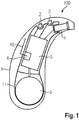
- Fig. 1 only the essential elements of a hearing aid 100 are shown without faithfully reproducing their positions, connections or shapes.
- Hearing aid 100 shown is a hearing aid 100 for supporting behind the ear.
- the invention is also conceivable for in-the-ear hearing aids, which then results in a different arrangement of the components shown.
- the hearing aid 100 has a housing 1 made of plastic, in which a frame 11 is inserted.
- the frame 11 is an injection molded plastic part.
- the frame 11 is generally used for holding electrical and electronic components of the hearing aid 100 and for fixing these assemblies in certain positions relative to each other.
- one or more microphones 2 are arranged to receive sound (ie, acoustic signals) from the environment.
- a printed circuit board (PCB) which carries at least part of the said electrical or electronic components, is folded into the frame 11 for this purpose.
- the microphones 2 are acousto-electrical converters for converting the sound into audio signals.
- the output signal of the signal processing device 3 is transmitted to a loudspeaker or receiver 4, which outputs an acoustic signal.
- the sound is optionally transmitted via a sound tube, which is fixed with an earmold in the ear canal, to the eardrum of the device carrier.
- the power supply of the hearing aid and in particular the signal processing device 3 is carried out by a likewise integrated into the housing 1 battery 5.
- the signal processing device 3, earpiece 4 and battery 5 are also arranged in the frame 11, so that the frame with the components disposed therein simply removed from the housing can be, for example, to exchange the housing 1 can.
- the signal processing device 3 is also designed for processing electromagnetic waves.
- the signal processing device 3 has a transmitting and receiving device 6 for generating and detecting electromagnetic waves and / or for decoding.
- the transmitting and receiving device 6 is electrically connected to an antenna 10 to emit and receive electromagnetic waves.
- the antenna 10 is formed as an integral part of the frame 11, namely as a conductive structure integrated in the frame 11.
- the antenna 10 is applied directly to the frame 11. It is not spaced from the surface and not non-destructively detachable from the frame 11.
- the antenna 10 is applied in particular to the frame 11 in MID technology.
- laser direct structuring LDS
- the antenna 10 is printed directly on the frame 11.
- the surface superimposed on the frame 11 conductor structures are then optionally electrically insulated by a protective coating or coating and protected from damage.
- the Fig. 2 to 6 show a first embodiment of the frame 11 with the integrated therein antenna 10.
- an opening 30 is provided, under which the microphone 2 (or one of a plurality of microphones 2) is arranged.
- recesses of the frame 11 are used to hold the receiver 4 and the transmitting and receiving unit 6.
- the frame 11 forms a battery compartment 34 (s. Fig. 3 ) for receiving the battery 5.
- a sound tube is connected in the normal operation of the hearing aid 100, which directs the sound generated by the listener 4 to an insertable into the ear canal of a user earmold.
- the sound tube and earmold are in Fig. 2 not shown.
- the frame 11 is, when the hearing aid is intended to be worn on the ear, directed in its longitudinal direction 21 with the top or front 35 frontally in the direction of the wearer.
- a transverse direction 20 of the frame 11 is oriented perpendicular to the viewing direction of the carrier, approximately parallel to the connecting line between the ears of the wearer.
- Parts of the antenna 10 are disposed on the side surfaces or flanks 37 of the frame 11.
- the frame 11 is split longitudinally (i.e., perpendicular to the transverse direction 20) along a dividing plane or dividing plane 38 into two frame halves 42 and 43.
- the frame halves 42 and 43 are in this case connected after insertion of the modules housed therein by Verclipsung, screwing, bonding and / or by means of retaining pins.
- the antenna 10 has two parts, each having the form of an open loop and therefore hereinafter referred to as antenna loops 40 and 41.
- the antenna loop 40 is arranged on the frame half 42, while the antenna loop 41 is arranged on the other frame half 43.
- the two antenna loops 40 and 41 extend - viewed transversely to the dividing plane or parting plane 38 of the frame 11 - parallel to each other and thus aligned with each other.
- the antenna 10 is thus formed mirror-symmetrically with respect to the dividing plane or parting plane 38 of the frame 11.
- Each of the two antenna loops 40 and 41 has two ends 44 and 45 (see FIG. Fig. 4 ). Both ends 44 and 45 are respectively arranged at the same longitudinal end of the frame 11 (namely at the top or front 35). The two ends 44 of the two antenna loops 40 and 41 are electrically short-circuited to each other via an electrical cross-connection or bridge 46, which also bridges the separation of the two frame halves 42,43. The two other ends 45 are contacted with the transmitting and receiving device 6.
- the cross-connection or bridge 46 is at least partially formed by interconnects, hereinafter referred to as bridge conductors 47 and 48 (see. Fig. 6 ), and which are also applied in MID technology (in particular by means of LDS) directly on the frame halves 42 and 43 of the frame 11.
- the bridge conductor 47 connected to the antenna loop 40 is hereby applied to a cantilever structure 49 of the frame half 42, which extends over the entire width of the frame 11 as far as the opposite lateral surface of the other frame half 43. This is particularly evident in the Fig. 6 showing the frame 11 in the closed state with fully assembled frame halves 42 and 43; the Fig.
- FIG. 5 shows the frame 11 in a partially opened state in which the frame halves 42 and 43 are slightly apart.
- the bridge conductor 48 connected to the antenna loop 41 is applied to the frame half 43 in such a way that it meets the bridge conductor 47 at the end of the cantilever structure 49 at a junction 50.
- bridge conductors 47 and 49 are electrically connected to each other by a solder joint 51.
- the impact point 50 lying on the lateral surface of the frame half 43 in this case enables a process-advantageous lateral soldering of the bridge conductors 47 and 49.
- the frame half 43 is provided with a Kragmila 52, which extends to the lateral surface of the other frame half 42.
- the cantilever structures 49 and 52 engage tooth-like in the other frame half 43 and 42, respectively.
- the cantilever structures 49 and 52 thus bring about a mechanical stabilization of the frame 11. This stability is advantageous above all for the stabilization of the soldering point 51 between the bridge conductors 47, 48.
- the bridge conductor 47 extends between the cantilever structures 49 and 52. It is thereby protected and spaced apart from other electrical or electronic components so that electromagnetic interference between the antenna 10 and these other electrical or electronic components is avoided.
- the distribution of the antenna 10 on both frame halves 42 and 43 on the one hand facilitates the realization of the required antenna length.
- the symmetrical design of the antenna 10 with respect to the two frame halves 42 and 43 advantageously facilitates a side-independent use of the hearing aid 100.
- this feature allows one and the same housing 1 including the frame 11 and the components housed therein both for use on the left Ear as well as for use on the right ear to use.
- the frame 11 is made of a plastic having a much higher permittivity than the housing 1. It has been found that the increased permittivity of the frame material by dielectric interaction with the generated and received by the antenna 10 electromagnetic field a significant reduction in the antenna length allows.
- FIGS. 7 and 8 show a variant or second embodiment of the above-described hearing aid 100.
- the variant according to FIGS. 7 and 8 This differs from the above-described embodiment of the hearing aid 100 in that the bridge conductors 47 and 48 and the solder joint 51 are missing. Instead, the variant is after FIGS. 7 and 8 an electrically conductive retaining pin 60 is provided which passes through the two frame halves 42 and 43, so that the ends 44 of the two antenna loops 40 and 41 are electrically shorted together are.
- the retaining pin 60 is also used for mechanical fixation of the two frame halves 42 and 43 together.
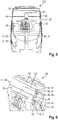
- FIG Fig. 9 A further embodiment of the hearing aid 100 is shown in FIG Fig. 9 shown.
- the essential difference from the previously described embodiments is the design of the bridge 46, with which the two antenna loops 40, 41 are short-circuited.
- the bridge 46 is completely formed on the outside of the frame 11 and guided over the top 36 of the frame 11.
- the frame 11 is in turn formed in two parts and on each frame half 42, 43 is in the region of the edge 37 each have an antenna loop 40, 41 positioned.
- the ends at the transition to the top 36 of the frame 11 antenna loops 40, 41 are here by external bridge conductors 61, 62 continued to the dividing plane 38 and abut on the parting plane 38 to each other or end here opposite each other.
- these bridge conductors 61, 62 are preferably connected to one another in an electrically conductive manner by means of a connecting element, for example a soldering point 64.
- the corresponding soldering point 64 or the corresponding connecting element is further preferably sunk in a recess 66 in the frame 11.
- the antenna 10 is then formed solely by externally on the frame 11 positioned conductor structures or conductor elements, which Fig. 10 again clarified. In this illustration, only the antenna 10 is shown and the frame 11 is hidden.
- FIG Fig. 11 to Fig. 13 Another feature of the hearing aid 100 according to the invention is shown in FIG Fig. 11 to Fig. 13 played.
- a second bridge 46 can be seen, which in turn connects the antenna loops 40, 41 with each other in an electrically conductive manner.
- one of the two bridges 46 in the region of the tip or the front 35 of the frame 11 is arranged and guided over the top 36 of the frame 11 and the other of the two bridges 46 is positioned in the region of the front 35 opposite rear side of the frame 11 and also guided over the top 36 of the frame 11.
- the second bridge 46 is formed by two bridge conductors 67, 68 which are electrically conductively connected to one another in the region of the dividing plane 38 via a soldering point 64 arranged in a depression 66 or another connecting element.
- the two antenna loops 40, 41 are asymmetrical to one another.
- the asymmetrical design of the two antenna loops 40, 41 is preferably selected if a symmetrical design of the antenna loops 40, 41 would lead to stronger electromagnetic interference between the antenna 10 and the other electrical or electronic components in or on the frame 11.
- the asymmetry between the two antenna loops 40 and 41 is preferably low.
- the 40, 41 are designed as symmetrical as possible, in particular avoiding the above disturbances.
Landscapes
- Engineering & Computer Science (AREA)
- Health & Medical Sciences (AREA)
- General Health & Medical Sciences (AREA)
- Neurosurgery (AREA)
- Otolaryngology (AREA)
- Physics & Mathematics (AREA)
- Acoustics & Sound (AREA)
- Signal Processing (AREA)
- Computer Networks & Wireless Communication (AREA)
- Manufacturing & Machinery (AREA)
- Support Of Aerials (AREA)
Claims (11)
- Appareil d'aide auditive (100), comprenant un boîtier (1), comprenant un cadre (11) inséré dans le boîtier (1) servant à accueillir des sous-ensembles électriques ou électroniques, lesquels comportent une unité d'émission et/ou de réception (6) pour des ondes électromagnétiques, et comprenant aussi une antenne (10) associée, l'antenne (10), étant réalisée sous la forme d'un élément constitutif intégral du cadre (11), sous la forme d'une pièce emboutie et cintrée ou sous la forme d'une pièce insérée en métal,- l'antenne (10) comportant deux parties (40, 41), qui sont respectivement réalisées sous la forme de boucles ouvertes pourvues de deux extrémités (44, 45), les deux parties (40, 41) en forme de boucle de l'antenne (10) étant court-circuitées électriquement l'une avec l'autre respectivement par une extrémité (44),- les extrémités (44, 45) des deux parties (40, 41) de l'antenne (10) étant disposées au niveau de la même extrémité longitudinale du cadre (11),- les deux parties (40, 41) en forme de boucle de l'antenne (10) étant court-circuitées l'une avec l'autre par le biais d'un cavalier (46), le cavalier (46) étant notamment réalisé sous la forme d'un élément constitutif intégral du cadre (11),
et- les deux parties (40, 41) en forme de boucle de l'antenne (10) étant en plus court-circuitées l'une avec l'autre par le biais d'un cavalier (46) supplémentaire, les deux cavaliers (46) étant disposés de manière notamment séparée l'un de l'autre dans l'espace. - Appareil d'aide auditive (100) selon la revendication 1, caractérisé en ce que le cavalier (46) est formé dans la zone d'un logement de pile (34).
- Appareil d'aide auditive (100) selon la revendication 1 ou 2, caractérisé en ce que le cavalier (46) est formé par des structures (61, 62, 64, 67, 68) conductrices positionnées du côté extérieur au niveau du cadre (11).
- Appareil d'aide auditive (100) selon l'une des revendications 1 à 3, caractérisé en ce que les deux parties (40, 41) en forme de boucle de l'antenne (10) sont positionnées sur deux flancs (37) mutuellement opposés du cadre (11) et en ce que le cavalier (46) est guidé au niveau du cadre (11) notamment par le biais d'un côté supérieur (36).
- Appareil d'aide auditive (100) selon l'une des revendications 1 à 4, caractérisé en ce que l'un des cavaliers (46) est disposé dans la zone d'un front (35) du cadre (11) et l'un des cavaliers (46) est disposé dans la zone d'un côté arrière du cadre (11) à l'opposé du front (35).
- Appareil d'aide auditive (100) selon l'une des revendications 1 à 5, caractérisé en ce que les deux parties (40, 41) en forme de boucle de l'antenne (10) sont court-circuitées l'une avec l'autre par le biais d'au moins un conducteur en pont (47, 48, 61, 62, 67, 68), le ou chaque conducteur en pont (47, 48) étant réalisé sous la forme d'un élément constitutif intégral du cadre (11).
- Appareil d'aide auditive selon l'une des revendications 1 à 6, caractérisé en ce que le cadre (11) est constitué de deux moitiés de cadre (42, 43), l'une des deux parties (40, 41) de l'antenne (10) étant respectivement disposée sur l'une des deux moitiés de cadre (42, 43).
- Appareil d'aide auditive selon la revendication 7, caractérisé en ce que les deux parties (40, 41) de l'antenne (10) sont de configuration symétrique l'une par rapport à l'autre en référence à un plan de séparation (38) qui sépare les moitiés de cadre (42, 43).
- Appareil d'aide auditive selon la revendication 7 ou 8, caractérisé en ce que les deux parties (40, 41) en forme de boucle de l'antenne (10) sont court-circuitées l'une avec l'autre par le biais de deux conducteurs en pont (47, 48), lesquels sont réalisés sous la forme d'éléments constitutifs intégraux du cadre (11), l'un desdits conducteurs en pont (47, 48) étant respectivement disposé sur l'une des deux moitiés de cadre (42, 43) et les deux conducteurs en pont (47, 48) étant brasés l'un à l'autre.
- Appareil d'aide auditive selon la revendication 9, caractérisé en ce que l'un desdits conducteurs en pont (47, 48) est disposé sur une structure en porte-à-faux (49) de l'une des deux moitiés de cadre (42, 43), laquelle s'étend sur toute la largeur du cadre (11) jusqu'à la surface latérale de l'autre moitié de cadre (43), et lesdits conducteurs en pont (47, 48) étant brasés au niveau de cette surface de l'autre moitié de cadre (43).
- Appareil d'aide auditive selon l'une des revendications 1 à 10, caractérisé en ce que le cadre (11) est fabriqué dans un matériau non conducteur qui possède une permittivité supérieure à celle du matériau du boîtier (1).
Priority Applications (1)
| Application Number | Priority Date | Filing Date | Title |
|---|---|---|---|
| EP18185304.5A EP3413394A1 (fr) | 2016-11-14 | 2017-11-13 | Appareil de correction auditive pourvu de cadre électronique et d'antenne intégrée audit appareil |
Applications Claiming Priority (1)
| Application Number | Priority Date | Filing Date | Title |
|---|---|---|---|
| DE102016222323.2A DE102016222323A1 (de) | 2016-11-14 | 2016-11-14 | Hörhilfegerät mit Elektronikrahmen und darin integrierter Antenne |
Related Child Applications (3)
| Application Number | Title | Priority Date | Filing Date |
|---|---|---|---|
| EP18185304.5A Division EP3413394A1 (fr) | 2016-11-14 | 2017-11-13 | Appareil de correction auditive pourvu de cadre électronique et d'antenne intégrée audit appareil |
| EP18185304.5A Previously-Filed-Application EP3413394A1 (fr) | 2016-11-14 | 2017-11-13 | Appareil de correction auditive pourvu de cadre électronique et d'antenne intégrée audit appareil |
| EP18185304.5A Division-Into EP3413394A1 (fr) | 2016-11-14 | 2017-11-13 | Appareil de correction auditive pourvu de cadre électronique et d'antenne intégrée audit appareil |
Publications (2)
| Publication Number | Publication Date |
|---|---|
| EP3322032A1 EP3322032A1 (fr) | 2018-05-16 |
| EP3322032B1 true EP3322032B1 (fr) | 2019-06-12 |
Family
ID=60327121
Family Applications (2)
| Application Number | Title | Priority Date | Filing Date |
|---|---|---|---|
| EP17201454.0A Active EP3322032B1 (fr) | 2016-11-14 | 2017-11-13 | Appareil de correction auditive pourvu de cadre électronique et d'antenne intégrée audit appareil |
| EP18185304.5A Withdrawn EP3413394A1 (fr) | 2016-11-14 | 2017-11-13 | Appareil de correction auditive pourvu de cadre électronique et d'antenne intégrée audit appareil |
Family Applications After (1)
| Application Number | Title | Priority Date | Filing Date |
|---|---|---|---|
| EP18185304.5A Withdrawn EP3413394A1 (fr) | 2016-11-14 | 2017-11-13 | Appareil de correction auditive pourvu de cadre électronique et d'antenne intégrée audit appareil |
Country Status (6)
| Country | Link |
|---|---|
| US (1) | US10362419B2 (fr) |
| EP (2) | EP3322032B1 (fr) |
| CN (1) | CN108076423B (fr) |
| AU (1) | AU2017261480B2 (fr) |
| DE (1) | DE102016222323A1 (fr) |
| DK (1) | DK3322032T3 (fr) |
Families Citing this family (5)
| Publication number | Priority date | Publication date | Assignee | Title |
|---|---|---|---|---|
| DE102018207179B4 (de) * | 2018-05-08 | 2020-03-19 | Sivantos Pte. Ltd. | Hörhilfegerät mit Elektronikrahmen und darin integrierter Antenne |
| CN213818098U (zh) * | 2018-06-04 | 2021-07-27 | 楼氏电子(苏州)有限公司 | 麦克风装置 |
| DE102018214199B3 (de) | 2018-08-22 | 2020-01-30 | Sivantos Pte. Ltd. | Performante magnetisch induktive Antenne für ein Hörinstrument |
| US10841716B2 (en) * | 2019-03-29 | 2020-11-17 | Sonova Ag | Hearing device with two-half loop antenna |
| EP3972288A1 (fr) * | 2020-09-17 | 2022-03-23 | Sonova AG | Dispositif auditif |
Family Cites Families (17)
| Publication number | Priority date | Publication date | Assignee | Title |
|---|---|---|---|---|
| DE102005008063B4 (de) * | 2005-02-22 | 2008-05-15 | Fraunhofer-Gesellschaft zur Förderung der angewandten Forschung e.V. | Antenne |
| JP5149896B2 (ja) * | 2006-06-20 | 2013-02-20 | ヴェーデクス・アクティーセルスカプ | 補聴器ハウジング,補聴器,および補聴器の製造方法 |
| EP1981176A1 (fr) * | 2007-04-11 | 2008-10-15 | Oticon A/S | Dispositif de communication sans fil pour couplage inductif sur un autre dispositif |
| US8565457B2 (en) | 2008-12-19 | 2013-10-22 | Starkey Laboratories, Inc. | Antennas for standard fit hearing assistance devices |
| US8699733B2 (en) * | 2008-12-19 | 2014-04-15 | Starkey Laboratories, Inc. | Parallel antennas for standard fit hearing assistance devices |
| CN101997163B (zh) * | 2009-08-27 | 2014-01-01 | 深圳富泰宏精密工业有限公司 | 天线及应用该天线的无线通信装置 |
| EP2606407A2 (fr) * | 2010-08-19 | 2013-06-26 | Apple Inc. | Dispositif électronique portatif |
| DK2725655T3 (da) | 2010-10-12 | 2021-09-20 | Gn Hearing As | Antennesystem til et høreapparat |
| DK201270410A (en) | 2012-07-06 | 2014-01-07 | Gn Resound As | BTE hearing aid with an antenna partition plane |
| EP2932559B1 (fr) | 2012-12-12 | 2021-09-22 | Sivantos Pte. Ltd. | Antenne modulaire pour appareils d'aide auditive |
| US9237404B2 (en) * | 2012-12-28 | 2016-01-12 | Gn Resound A/S | Dipole antenna for a hearing aid |
| EP2835862B1 (fr) * | 2013-08-08 | 2019-11-13 | Nxp B.V. | Antenne |
| EP2835863B1 (fr) * | 2013-08-09 | 2019-12-11 | Oticon A/s | Appareil auditif doté d'une antenne RF |
| US9408003B2 (en) * | 2013-11-11 | 2016-08-02 | Gn Resound A/S | Hearing aid with an antenna |
| US9237405B2 (en) * | 2013-11-11 | 2016-01-12 | Gn Resound A/S | Hearing aid with an antenna |
| US9743198B2 (en) * | 2014-01-15 | 2017-08-22 | Starkey Laboratories, Inc. | Systems and methods for hearing assistance device antenna |
| EP3257267B1 (fr) | 2015-02-09 | 2021-06-30 | Starkey Laboratories, Inc. | Antenne d'assistance auditive à fonctionnement symétrique |
-
2016
- 2016-11-14 DE DE102016222323.2A patent/DE102016222323A1/de not_active Withdrawn
-
2017
- 2017-11-09 US US15/807,626 patent/US10362419B2/en active Active
- 2017-11-13 EP EP17201454.0A patent/EP3322032B1/fr active Active
- 2017-11-13 EP EP18185304.5A patent/EP3413394A1/fr not_active Withdrawn
- 2017-11-13 DK DK17201454.0T patent/DK3322032T3/da active
- 2017-11-14 CN CN201711123025.0A patent/CN108076423B/zh active Active
- 2017-11-14 AU AU2017261480A patent/AU2017261480B2/en not_active Expired - Fee Related
Non-Patent Citations (1)
| Title |
|---|
| None * |
Also Published As
| Publication number | Publication date |
|---|---|
| EP3413394A1 (fr) | 2018-12-12 |
| US20180139548A1 (en) | 2018-05-17 |
| CN108076423A (zh) | 2018-05-25 |
| AU2017261480A1 (en) | 2018-05-31 |
| EP3322032A1 (fr) | 2018-05-16 |
| DE102016222323A1 (de) | 2018-05-17 |
| US10362419B2 (en) | 2019-07-23 |
| AU2017261480B2 (en) | 2019-03-14 |
| CN108076423B (zh) | 2020-10-16 |
| DK3322032T3 (da) | 2019-09-23 |
Similar Documents
| Publication | Publication Date | Title |
|---|---|---|
| EP3322032B1 (fr) | Appareil de correction auditive pourvu de cadre électronique et d'antenne intégrée audit appareil | |
| EP2932559B1 (fr) | Antenne modulaire pour appareils d'aide auditive | |
| EP2932560B2 (fr) | Dipôle replié pour prothèse auditive | |
| EP2811761B1 (fr) | Dispositif d'antenne pour appareils auditifs | |
| DE102013204681B4 (de) | Binaurales Hörinstrument sowie Ohrstück | |
| EP3567672B1 (fr) | Appareil d'aide auditive pourvu de cadre électronique et d'antenne intégrée audit appareil | |
| EP3490272B1 (fr) | Lot d'appareils auditives et procédé de fabrication d'un lot d'appareils auditives | |
| WO2019105949A1 (fr) | Appareil auditif modulaire | |
| DE102016207844A1 (de) | Hörgerät | |
| EP3313093A1 (fr) | Appareil de correction auditive et dispositif de traitement de signal pour un appareil de correction auditive | |
| EP3836565B1 (fr) | Carte de circuit imprimé d'un appareil auditif | |
| EP3197180A1 (fr) | Appareil auditif | |
| EP2911312B1 (fr) | Antenne dotée de dispositif de protection et procédé de fabrication | |
| DE102017220187A1 (de) | Hörhilfegerät | |
| DE102020201480A1 (de) | Hörgerät | |
| DE102017210448B3 (de) | Hörgerät | |
| EP3396979B1 (fr) | Procédé de fabrication d'un cadre de support d'un appareil d'aide auditive et cadre de support ainsi qu'appareil d'aide auditive | |
| DE102021200195B4 (de) | Hörgerät | |
| EP3863304B1 (fr) | Appareil auditif avec antenne à couplage inductif | |
| EP4054208A1 (fr) | Appareil auditif, antenne pour un appareil auditif et procédé de fabrication d'un appareil auditif | |
| DE102018201025A1 (de) | Hörgerät | |
| DE102007045750A1 (de) | Schaltungsanordnung mit gestapelten SMD-Bauteilen und entsprechendes Herstellungsverfahren | |
| DE102009007219A1 (de) | Faceplatemodul mit verriegelbarem Mikrofon |
Legal Events
| Date | Code | Title | Description |
|---|---|---|---|
| PUAI | Public reference made under article 153(3) epc to a published international application that has entered the european phase |
Free format text: ORIGINAL CODE: 0009012 |
|
| STAA | Information on the status of an ep patent application or granted ep patent |
Free format text: STATUS: THE APPLICATION HAS BEEN PUBLISHED |
|
| AK | Designated contracting states |
Kind code of ref document: A1 Designated state(s): AL AT BE BG CH CY CZ DE DK EE ES FI FR GB GR HR HU IE IS IT LI LT LU LV MC MK MT NL NO PL PT RO RS SE SI SK SM TR |
|
| AX | Request for extension of the european patent |
Extension state: BA ME |
|
| STAA | Information on the status of an ep patent application or granted ep patent |
Free format text: STATUS: REQUEST FOR EXAMINATION WAS MADE |
|
| 17P | Request for examination filed |
Effective date: 20181031 |
|
| RBV | Designated contracting states (corrected) |
Designated state(s): AL AT BE BG CH CY CZ DE DK EE ES FI FR GB GR HR HU IE IS IT LI LT LU LV MC MK MT NL NO PL PT RO RS SE SI SK SM TR |
|
| RIC1 | Information provided on ipc code assigned before grant |
Ipc: H04R 25/00 20060101ALI20190115BHEP Ipc: H01Q 1/27 20060101AFI20190115BHEP Ipc: H01Q 7/00 20060101ALI20190115BHEP Ipc: H01Q 9/16 20060101ALI20190115BHEP Ipc: H01Q 1/38 20060101ALN20190115BHEP |
|
| GRAP | Despatch of communication of intention to grant a patent |
Free format text: ORIGINAL CODE: EPIDOSNIGR1 |
|
| STAA | Information on the status of an ep patent application or granted ep patent |
Free format text: STATUS: GRANT OF PATENT IS INTENDED |
|
| INTG | Intention to grant announced |
Effective date: 20190227 |
|
| GRAS | Grant fee paid |
Free format text: ORIGINAL CODE: EPIDOSNIGR3 |
|
| GRAA | (expected) grant |
Free format text: ORIGINAL CODE: 0009210 |
|
| STAA | Information on the status of an ep patent application or granted ep patent |
Free format text: STATUS: THE PATENT HAS BEEN GRANTED |
|
| AK | Designated contracting states |
Kind code of ref document: B1 Designated state(s): AL AT BE BG CH CY CZ DE DK EE ES FI FR GB GR HR HU IE IS IT LI LT LU LV MC MK MT NL NO PL PT RO RS SE SI SK SM TR |
|
| REG | Reference to a national code |
Ref country code: GB Ref legal event code: FG4D Free format text: NOT ENGLISH |
|
| REG | Reference to a national code |
Ref country code: CH Ref legal event code: EP |
|
| REG | Reference to a national code |
Ref country code: AT Ref legal event code: REF Ref document number: 1143809 Country of ref document: AT Kind code of ref document: T Effective date: 20190615 |
|
| REG | Reference to a national code |
Ref country code: DE Ref legal event code: R096 Ref document number: 502017001541 Country of ref document: DE |
|
| REG | Reference to a national code |
Ref country code: IE Ref legal event code: FG4D Free format text: LANGUAGE OF EP DOCUMENT: GERMAN |
|
| REG | Reference to a national code |
Ref country code: CH Ref legal event code: NV Representative=s name: E. BLUM AND CO. AG PATENT- UND MARKENANWAELTE , CH |
|
| REG | Reference to a national code |
Ref country code: DK Ref legal event code: T3 Effective date: 20190919 |
|
| REG | Reference to a national code |
Ref country code: NL Ref legal event code: MP Effective date: 20190612 |
|
| REG | Reference to a national code |
Ref country code: LT Ref legal event code: MG4D |
|
| PG25 | Lapsed in a contracting state [announced via postgrant information from national office to epo] |
Ref country code: SE Free format text: LAPSE BECAUSE OF FAILURE TO SUBMIT A TRANSLATION OF THE DESCRIPTION OR TO PAY THE FEE WITHIN THE PRESCRIBED TIME-LIMIT Effective date: 20190612 Ref country code: HR Free format text: LAPSE BECAUSE OF FAILURE TO SUBMIT A TRANSLATION OF THE DESCRIPTION OR TO PAY THE FEE WITHIN THE PRESCRIBED TIME-LIMIT Effective date: 20190612 Ref country code: LT Free format text: LAPSE BECAUSE OF FAILURE TO SUBMIT A TRANSLATION OF THE DESCRIPTION OR TO PAY THE FEE WITHIN THE PRESCRIBED TIME-LIMIT Effective date: 20190612 Ref country code: AL Free format text: LAPSE BECAUSE OF FAILURE TO SUBMIT A TRANSLATION OF THE DESCRIPTION OR TO PAY THE FEE WITHIN THE PRESCRIBED TIME-LIMIT Effective date: 20190612 Ref country code: NO Free format text: LAPSE BECAUSE OF FAILURE TO SUBMIT A TRANSLATION OF THE DESCRIPTION OR TO PAY THE FEE WITHIN THE PRESCRIBED TIME-LIMIT Effective date: 20190912 Ref country code: FI Free format text: LAPSE BECAUSE OF FAILURE TO SUBMIT A TRANSLATION OF THE DESCRIPTION OR TO PAY THE FEE WITHIN THE PRESCRIBED TIME-LIMIT Effective date: 20190612 |
|
| PG25 | Lapsed in a contracting state [announced via postgrant information from national office to epo] |
Ref country code: GR Free format text: LAPSE BECAUSE OF FAILURE TO SUBMIT A TRANSLATION OF THE DESCRIPTION OR TO PAY THE FEE WITHIN THE PRESCRIBED TIME-LIMIT Effective date: 20190913 Ref country code: BG Free format text: LAPSE BECAUSE OF FAILURE TO SUBMIT A TRANSLATION OF THE DESCRIPTION OR TO PAY THE FEE WITHIN THE PRESCRIBED TIME-LIMIT Effective date: 20190912 Ref country code: RS Free format text: LAPSE BECAUSE OF FAILURE TO SUBMIT A TRANSLATION OF THE DESCRIPTION OR TO PAY THE FEE WITHIN THE PRESCRIBED TIME-LIMIT Effective date: 20190612 Ref country code: LV Free format text: LAPSE BECAUSE OF FAILURE TO SUBMIT A TRANSLATION OF THE DESCRIPTION OR TO PAY THE FEE WITHIN THE PRESCRIBED TIME-LIMIT Effective date: 20190612 |
|
| PG25 | Lapsed in a contracting state [announced via postgrant information from national office to epo] |
Ref country code: NL Free format text: LAPSE BECAUSE OF FAILURE TO SUBMIT A TRANSLATION OF THE DESCRIPTION OR TO PAY THE FEE WITHIN THE PRESCRIBED TIME-LIMIT Effective date: 20190612 Ref country code: SK Free format text: LAPSE BECAUSE OF FAILURE TO SUBMIT A TRANSLATION OF THE DESCRIPTION OR TO PAY THE FEE WITHIN THE PRESCRIBED TIME-LIMIT Effective date: 20190612 Ref country code: PT Free format text: LAPSE BECAUSE OF FAILURE TO SUBMIT A TRANSLATION OF THE DESCRIPTION OR TO PAY THE FEE WITHIN THE PRESCRIBED TIME-LIMIT Effective date: 20191014 Ref country code: RO Free format text: LAPSE BECAUSE OF FAILURE TO SUBMIT A TRANSLATION OF THE DESCRIPTION OR TO PAY THE FEE WITHIN THE PRESCRIBED TIME-LIMIT Effective date: 20190612 Ref country code: CZ Free format text: LAPSE BECAUSE OF FAILURE TO SUBMIT A TRANSLATION OF THE DESCRIPTION OR TO PAY THE FEE WITHIN THE PRESCRIBED TIME-LIMIT Effective date: 20190612 Ref country code: EE Free format text: LAPSE BECAUSE OF FAILURE TO SUBMIT A TRANSLATION OF THE DESCRIPTION OR TO PAY THE FEE WITHIN THE PRESCRIBED TIME-LIMIT Effective date: 20190612 |
|
| PG25 | Lapsed in a contracting state [announced via postgrant information from national office to epo] |
Ref country code: IS Free format text: LAPSE BECAUSE OF FAILURE TO SUBMIT A TRANSLATION OF THE DESCRIPTION OR TO PAY THE FEE WITHIN THE PRESCRIBED TIME-LIMIT Effective date: 20191012 Ref country code: SM Free format text: LAPSE BECAUSE OF FAILURE TO SUBMIT A TRANSLATION OF THE DESCRIPTION OR TO PAY THE FEE WITHIN THE PRESCRIBED TIME-LIMIT Effective date: 20190612 Ref country code: ES Free format text: LAPSE BECAUSE OF FAILURE TO SUBMIT A TRANSLATION OF THE DESCRIPTION OR TO PAY THE FEE WITHIN THE PRESCRIBED TIME-LIMIT Effective date: 20190612 Ref country code: IT Free format text: LAPSE BECAUSE OF FAILURE TO SUBMIT A TRANSLATION OF THE DESCRIPTION OR TO PAY THE FEE WITHIN THE PRESCRIBED TIME-LIMIT Effective date: 20190612 |
|
| REG | Reference to a national code |
Ref country code: DE Ref legal event code: R097 Ref document number: 502017001541 Country of ref document: DE |
|
| PG25 | Lapsed in a contracting state [announced via postgrant information from national office to epo] |
Ref country code: TR Free format text: LAPSE BECAUSE OF FAILURE TO SUBMIT A TRANSLATION OF THE DESCRIPTION OR TO PAY THE FEE WITHIN THE PRESCRIBED TIME-LIMIT Effective date: 20190612 |
|
| PLBE | No opposition filed within time limit |
Free format text: ORIGINAL CODE: 0009261 |
|
| STAA | Information on the status of an ep patent application or granted ep patent |
Free format text: STATUS: NO OPPOSITION FILED WITHIN TIME LIMIT |
|
| PG25 | Lapsed in a contracting state [announced via postgrant information from national office to epo] |
Ref country code: PL Free format text: LAPSE BECAUSE OF FAILURE TO SUBMIT A TRANSLATION OF THE DESCRIPTION OR TO PAY THE FEE WITHIN THE PRESCRIBED TIME-LIMIT Effective date: 20190612 |
|
| 26N | No opposition filed |
Effective date: 20200313 |
|
| PG25 | Lapsed in a contracting state [announced via postgrant information from national office to epo] |
Ref country code: IS Free format text: LAPSE BECAUSE OF FAILURE TO SUBMIT A TRANSLATION OF THE DESCRIPTION OR TO PAY THE FEE WITHIN THE PRESCRIBED TIME-LIMIT Effective date: 20200224 Ref country code: SI Free format text: LAPSE BECAUSE OF FAILURE TO SUBMIT A TRANSLATION OF THE DESCRIPTION OR TO PAY THE FEE WITHIN THE PRESCRIBED TIME-LIMIT Effective date: 20190612 |
|
| PG2D | Information on lapse in contracting state deleted |
Ref country code: IS |
|
| PG25 | Lapsed in a contracting state [announced via postgrant information from national office to epo] |
Ref country code: MC Free format text: LAPSE BECAUSE OF FAILURE TO SUBMIT A TRANSLATION OF THE DESCRIPTION OR TO PAY THE FEE WITHIN THE PRESCRIBED TIME-LIMIT Effective date: 20190612 Ref country code: LU Free format text: LAPSE BECAUSE OF NON-PAYMENT OF DUE FEES Effective date: 20191113 |
|
| REG | Reference to a national code |
Ref country code: BE Ref legal event code: MM Effective date: 20191130 |
|
| PG25 | Lapsed in a contracting state [announced via postgrant information from national office to epo] |
Ref country code: IE Free format text: LAPSE BECAUSE OF NON-PAYMENT OF DUE FEES Effective date: 20191113 |
|
| PG25 | Lapsed in a contracting state [announced via postgrant information from national office to epo] |
Ref country code: BE Free format text: LAPSE BECAUSE OF NON-PAYMENT OF DUE FEES Effective date: 20191130 |
|
| PG25 | Lapsed in a contracting state [announced via postgrant information from national office to epo] |
Ref country code: CY Free format text: LAPSE BECAUSE OF FAILURE TO SUBMIT A TRANSLATION OF THE DESCRIPTION OR TO PAY THE FEE WITHIN THE PRESCRIBED TIME-LIMIT Effective date: 20190612 |
|
| PG25 | Lapsed in a contracting state [announced via postgrant information from national office to epo] |
Ref country code: MT Free format text: LAPSE BECAUSE OF FAILURE TO SUBMIT A TRANSLATION OF THE DESCRIPTION OR TO PAY THE FEE WITHIN THE PRESCRIBED TIME-LIMIT Effective date: 20190612 Ref country code: HU Free format text: LAPSE BECAUSE OF FAILURE TO SUBMIT A TRANSLATION OF THE DESCRIPTION OR TO PAY THE FEE WITHIN THE PRESCRIBED TIME-LIMIT; INVALID AB INITIO Effective date: 20171113 |
|
| PG25 | Lapsed in a contracting state [announced via postgrant information from national office to epo] |
Ref country code: MK Free format text: LAPSE BECAUSE OF FAILURE TO SUBMIT A TRANSLATION OF THE DESCRIPTION OR TO PAY THE FEE WITHIN THE PRESCRIBED TIME-LIMIT Effective date: 20190612 |
|
| REG | Reference to a national code |
Ref country code: AT Ref legal event code: MM01 Ref document number: 1143809 Country of ref document: AT Kind code of ref document: T Effective date: 20221113 |
|
| PGFP | Annual fee paid to national office [announced via postgrant information from national office to epo] |
Ref country code: GB Payment date: 20231123 Year of fee payment: 7 |
|
| PG25 | Lapsed in a contracting state [announced via postgrant information from national office to epo] |
Ref country code: AT Free format text: LAPSE BECAUSE OF NON-PAYMENT OF DUE FEES Effective date: 20221113 |
|
| PGFP | Annual fee paid to national office [announced via postgrant information from national office to epo] |
Ref country code: FR Payment date: 20231124 Year of fee payment: 7 Ref country code: DK Payment date: 20231122 Year of fee payment: 7 Ref country code: DE Payment date: 20231120 Year of fee payment: 7 Ref country code: CH Payment date: 20231201 Year of fee payment: 7 |