EP3321143B1 - Verfahren zur steuerung einer bremsvorrichtung und bremssteuerungsvorrichtung - Google Patents
Verfahren zur steuerung einer bremsvorrichtung und bremssteuerungsvorrichtung Download PDFInfo
- Publication number
- EP3321143B1 EP3321143B1 EP15898215.7A EP15898215A EP3321143B1 EP 3321143 B1 EP3321143 B1 EP 3321143B1 EP 15898215 A EP15898215 A EP 15898215A EP 3321143 B1 EP3321143 B1 EP 3321143B1
- Authority
- EP
- European Patent Office
- Prior art keywords
- vehicle
- towed
- braking
- towing vehicle
- towed vehicles
- Prior art date
- Legal status (The legal status is an assumption and is not a legal conclusion. Google has not performed a legal analysis and makes no representation as to the accuracy of the status listed.)
- Active
Links
Images



Classifications
-
- B—PERFORMING OPERATIONS; TRANSPORTING
- B60—VEHICLES IN GENERAL
- B60T—VEHICLE BRAKE CONTROL SYSTEMS OR PARTS THEREOF; BRAKE CONTROL SYSTEMS OR PARTS THEREOF, IN GENERAL; ARRANGEMENT OF BRAKING ELEMENTS ON VEHICLES IN GENERAL; PORTABLE DEVICES FOR PREVENTING UNWANTED MOVEMENT OF VEHICLES; VEHICLE MODIFICATIONS TO FACILITATE COOLING OF BRAKES
- B60T13/00—Transmitting braking action from initiating means to ultimate brake actuator with power assistance or drive; Brake systems incorporating such transmitting means, e.g. air-pressure brake systems
- B60T13/10—Transmitting braking action from initiating means to ultimate brake actuator with power assistance or drive; Brake systems incorporating such transmitting means, e.g. air-pressure brake systems with fluid assistance, drive, or release
- B60T13/66—Electrical control in fluid-pressure brake systems
- B60T13/665—Electrical control in fluid-pressure brake systems the systems being specially adapted for transferring two or more command signals, e.g. railway systems
-
- B—PERFORMING OPERATIONS; TRANSPORTING
- B60—VEHICLES IN GENERAL
- B60T—VEHICLE BRAKE CONTROL SYSTEMS OR PARTS THEREOF; BRAKE CONTROL SYSTEMS OR PARTS THEREOF, IN GENERAL; ARRANGEMENT OF BRAKING ELEMENTS ON VEHICLES IN GENERAL; PORTABLE DEVICES FOR PREVENTING UNWANTED MOVEMENT OF VEHICLES; VEHICLE MODIFICATIONS TO FACILITATE COOLING OF BRAKES
- B60T7/00—Brake-action initiating means
- B60T7/12—Brake-action initiating means for automatic initiation; for initiation not subject to will of driver or passenger
- B60T7/20—Brake-action initiating means for automatic initiation; for initiation not subject to will of driver or passenger specially for trailers, e.g. in case of uncoupling of or overrunning by trailer
-
- B—PERFORMING OPERATIONS; TRANSPORTING
- B60—VEHICLES IN GENERAL
- B60T—VEHICLE BRAKE CONTROL SYSTEMS OR PARTS THEREOF; BRAKE CONTROL SYSTEMS OR PARTS THEREOF, IN GENERAL; ARRANGEMENT OF BRAKING ELEMENTS ON VEHICLES IN GENERAL; PORTABLE DEVICES FOR PREVENTING UNWANTED MOVEMENT OF VEHICLES; VEHICLE MODIFICATIONS TO FACILITATE COOLING OF BRAKES
- B60T8/00—Arrangements for adjusting wheel-braking force to meet varying vehicular or ground-surface conditions, e.g. limiting or varying distribution of braking force
- B60T8/17—Using electrical or electronic regulation means to control braking
- B60T8/1701—Braking or traction control means specially adapted for particular types of vehicles
-
- B—PERFORMING OPERATIONS; TRANSPORTING
- B60—VEHICLES IN GENERAL
- B60L—PROPULSION OF ELECTRICALLY-PROPELLED VEHICLES; SUPPLYING ELECTRIC POWER FOR AUXILIARY EQUIPMENT OF ELECTRICALLY-PROPELLED VEHICLES; ELECTRODYNAMIC BRAKE SYSTEMS FOR VEHICLES IN GENERAL; MAGNETIC SUSPENSION OR LEVITATION FOR VEHICLES; MONITORING OPERATING VARIABLES OF ELECTRICALLY-PROPELLED VEHICLES; ELECTRIC SAFETY DEVICES FOR ELECTRICALLY-PROPELLED VEHICLES
- B60L15/00—Methods, circuits, or devices for controlling the traction-motor speed of electrically-propelled vehicles
- B60L15/20—Methods, circuits, or devices for controlling the traction-motor speed of electrically-propelled vehicles for control of the vehicle or its driving motor to achieve a desired performance, e.g. speed, torque, programmed variation of speed
-
- B—PERFORMING OPERATIONS; TRANSPORTING
- B60—VEHICLES IN GENERAL
- B60T—VEHICLE BRAKE CONTROL SYSTEMS OR PARTS THEREOF; BRAKE CONTROL SYSTEMS OR PARTS THEREOF, IN GENERAL; ARRANGEMENT OF BRAKING ELEMENTS ON VEHICLES IN GENERAL; PORTABLE DEVICES FOR PREVENTING UNWANTED MOVEMENT OF VEHICLES; VEHICLE MODIFICATIONS TO FACILITATE COOLING OF BRAKES
- B60T15/00—Construction arrangement, or operation of valves incorporated in power brake systems and not covered by groups B60T11/00 or B60T13/00
- B60T15/02—Application and release valves
- B60T15/36—Other control devices or valves characterised by definite functions
- B60T15/46—Other control devices or valves characterised by definite functions for retarding braking action to prevent rear vehicles of a vehicle train overtaking the forward ones
-
- B—PERFORMING OPERATIONS; TRANSPORTING
- B60—VEHICLES IN GENERAL
- B60T—VEHICLE BRAKE CONTROL SYSTEMS OR PARTS THEREOF; BRAKE CONTROL SYSTEMS OR PARTS THEREOF, IN GENERAL; ARRANGEMENT OF BRAKING ELEMENTS ON VEHICLES IN GENERAL; PORTABLE DEVICES FOR PREVENTING UNWANTED MOVEMENT OF VEHICLES; VEHICLE MODIFICATIONS TO FACILITATE COOLING OF BRAKES
- B60T17/00—Component parts, details, or accessories of power brake systems not covered by groups B60T8/00, B60T13/00 or B60T15/00, or presenting other characteristic features
- B60T17/18—Safety devices; Monitoring
- B60T17/22—Devices for monitoring or checking brake systems; Signal devices
- B60T17/228—Devices for monitoring or checking brake systems; Signal devices for railway vehicles
-
- B—PERFORMING OPERATIONS; TRANSPORTING
- B60—VEHICLES IN GENERAL
- B60T—VEHICLE BRAKE CONTROL SYSTEMS OR PARTS THEREOF; BRAKE CONTROL SYSTEMS OR PARTS THEREOF, IN GENERAL; ARRANGEMENT OF BRAKING ELEMENTS ON VEHICLES IN GENERAL; PORTABLE DEVICES FOR PREVENTING UNWANTED MOVEMENT OF VEHICLES; VEHICLE MODIFICATIONS TO FACILITATE COOLING OF BRAKES
- B60T7/00—Brake-action initiating means
- B60T7/12—Brake-action initiating means for automatic initiation; for initiation not subject to will of driver or passenger
- B60T7/128—Self-acting brakes of different types for railway vehicles
-
- B—PERFORMING OPERATIONS; TRANSPORTING
- B60—VEHICLES IN GENERAL
- B60T—VEHICLE BRAKE CONTROL SYSTEMS OR PARTS THEREOF; BRAKE CONTROL SYSTEMS OR PARTS THEREOF, IN GENERAL; ARRANGEMENT OF BRAKING ELEMENTS ON VEHICLES IN GENERAL; PORTABLE DEVICES FOR PREVENTING UNWANTED MOVEMENT OF VEHICLES; VEHICLE MODIFICATIONS TO FACILITATE COOLING OF BRAKES
- B60T7/00—Brake-action initiating means
- B60T7/12—Brake-action initiating means for automatic initiation; for initiation not subject to will of driver or passenger
- B60T7/22—Brake-action initiating means for automatic initiation; for initiation not subject to will of driver or passenger initiated by contact of vehicle, e.g. bumper, with an external object, e.g. another vehicle, or by means of contactless obstacle detectors mounted on the vehicle
-
- B—PERFORMING OPERATIONS; TRANSPORTING
- B61—RAILWAYS
- B61G—COUPLINGS; DRAUGHT AND BUFFING APPLIANCES
- B61G7/00—Details or accessories
- B61G7/14—Safety devices
-
- B—PERFORMING OPERATIONS; TRANSPORTING
- B60—VEHICLES IN GENERAL
- B60Y—INDEXING SCHEME RELATING TO ASPECTS CROSS-CUTTING VEHICLE TECHNOLOGY
- B60Y2300/00—Purposes or special features of road vehicle drive control systems
- B60Y2300/28—Purposes or special features of road vehicle drive control systems related to towing or towed situations
-
- Y—GENERAL TAGGING OF NEW TECHNOLOGICAL DEVELOPMENTS; GENERAL TAGGING OF CROSS-SECTIONAL TECHNOLOGIES SPANNING OVER SEVERAL SECTIONS OF THE IPC; TECHNICAL SUBJECTS COVERED BY FORMER USPC CROSS-REFERENCE ART COLLECTIONS [XRACs] AND DIGESTS
- Y02—TECHNOLOGIES OR APPLICATIONS FOR MITIGATION OR ADAPTATION AGAINST CLIMATE CHANGE
- Y02T—CLIMATE CHANGE MITIGATION TECHNOLOGIES RELATED TO TRANSPORTATION
- Y02T10/00—Road transport of goods or passengers
- Y02T10/60—Other road transportation technologies with climate change mitigation effect
- Y02T10/72—Electric energy management in electromobility
Definitions
- the present invention relates to a method for controlling a braking device and a braking control device for controlling the braking force of a plurality of towed vehicles that are towed by a towing vehicle.
- a technique for controlling a combination vehicle which comprises a towing vehicle and a plurality of towed vehicles, it is required that shocks and vibrations of the towed vehicles that are generated due to elongation of couplers that connect the combination vehicle be suppressed at the time of starting the combination vehicle.
- a technique in which, in a locomotive that tows passenger cars, when the locomotive accelerates in order to start, an increase in acceleration is suppressed immediately after acceleration is started, and the acceleration is increased after a certain amount of tensile load is applied between the passenger cars, in order to ameliorate sudden changes in the torque that are generated by the passenger cars (Patent Document 1).
- FR 2 774 343 A1 discloses a method for controlling a braking device which controls a braking force of towed vehicles in a combination vehicle having a towing vehicle and a plurality of the towed vehicles being towed by the towing vehicle, and in which coupling between the towing vehicle and a towed vehicle and coupling between the towed vehicles are carried out by couplers.
- Patent Document 1 Japanese Laid-Open Patent Application No. 2004-49000
- the problem to be solved by the present invention is how promptly to accelerate a combination vehicle while suppressing shocks and vibrations of the towed vehicles when starting the combination vehicle.
- the present invention solves the problem described above by controlling the timing at which braking force is imparted to the towed vehicles when the towing vehicle starts, in a combination vehicle in which a towing vehicle and the towed vehicle or vehicles, are respectively coupled to each other by couplers.
- the couplers are elongated to an appropriate length in a short period of time.
- the couplers are in an appropriately elongated state at the point in time in which the towing vehicle starts to accelerate in order to start, and it becomes possible for the combination vehicle to start while suppressing shocks and vibrations of the towed vehicles and to promptly accelerate the combination vehicle.
- Figure 1 is a schematic view illustrating a scenario in which a towing vehicle 1 comprising the braking control device 111 of the present embodiment is attempting to start a combination vehicle comprising the towing vehicle 1 and towed vehicles 2a-2c, while towing three towed vehicles 2a-2c.
- the configuration of the combination vehicle is realized by the respectively coupling of the towing vehicle 1 and the towed vehicles 2a-2c via couplers 4a-4c.
- the configuration of the combination vehicle is realized by the coupling of the towing vehicle 1 and a towed vehicle 2a via a coupler 4a, the coupling of the towed vehicle 2a and a towed vehicle 2b via a coupler 4b, and the coupling of the towed vehicle 2b and a towed vehicle 2c via a coupler 4c.
- Loads 21a-21c are respectively loaded on the towed vehicles 2a-2c.
- Figure 1 an example is shown in which there are three towed vehicles; however, the number of towed vehicles is not limited and may be any number greater than or equal to two.
- the towing vehicle 1 and the towed vehicles 2a-2c, which configure the combination vehicle are not particularly limited, and may be automobiles that can travel on roads, or railroad cars that travel on rails.
- the towing vehicle 1 may be any vehicle that can travel while towing towed vehicles 2a-2c, and includes, for example, vehicles that travel using an electric motor, an internal combustion engine, a steam engine, or the like as the prime mover.
- the couplers 4a-4c are not particularly limited, and in the example illustrated in Figure 1 , couplers that can expand and contract in accordance with the acceleration of the towing vehicle 1 are used. That is, the couplers 4a-4c are capable of expanding in accordance with the acceleration of the towing vehicle 1 and are capable of contracting in accordance with the deceleration of the towing vehicle 1.
- elastic members are incorporated in the couplers 4a-4c, and it is possible to cause the couplers 4a-4c to expand and contract by the elastic members expanding and contracting in accordance with the acceleration of the towing vehicle 1.
- the towing vehicle 1 is provided with a combination vehicle controller 11 for controlling the driving and braking of the combination vehicle, and a driving unit 12 for driving the towing vehicle 1, as illustrated in Figure 1 .
- the combination vehicle controller 11 is connected to control devices 22a-22c, which are respectively provided to the towed vehicles 2a-2c, via a coupling circuit 3, as illustrated in Figure 1 .
- the control devices 22a-22c that are connected to the combination vehicle controller 11 are able to respectively operate brakes 24a-24c of the towed vehicles 2a-2c via brake operating circuits 23a-23c to impart braking force to the wheels of the towed vehicles 2a-2c.
- the brakes 24a-24c are not particularly limited, and it is possible to use a disc brake or a drum brake, which are operated by controlling the fluid pressure of a fluid (oil, compressed air, or the like) with the control devices 22a-22c.
- the brakes 24a-24c may impart braking force without depending on fluid pressure, and, for example, an electric brake device may be used.
- FIG. 2 is a block diagram of the combination vehicle of the present embodiment.
- the combination vehicle controller 11 of the towing vehicle 1 is provided with a braking control device 111 for imparting braking force to the towed vehicles 2a-2c and a drive control device 112 for driving the driving unit 12 of the towing vehicle 1 in order to accelerate the towing vehicle 1, as illustrated in Figure 2 .
- the braking control device 111 provided relative to the combination vehicle controller 11 instructs the control devices 22a-22c of the towed vehicles 2a-2c via the coupling circuit 3 to operate the brakes 24a-24c to impart braking force to the towed vehicles 2a-2c.
- a brake may be provided to the towing vehicle 1, and the braking control device 111 may operate the brake of the towing vehicle 1 to impart braking force to the towing vehicle 1.
- the following control is carried out in a combination vehicle having such a configuration. That is, while the combination vehicle is stopped before the combination vehicle is started, the braking control device 111 sequentially imparts braking force to each of the towed vehicles, i.e., with respect to the towed vehicles 2a-2c, and drives the driving unit 12 of the towing vehicle 1. It is thereby possible to elongate the length of the couplers 4a-4c up to an expansion amount that corresponds to when the towing vehicle 1 is accelerated at the target acceleration, at the point in time in which the combination vehicle is actually started.
- the couplers 4a-4c expand and contract in accordance with the acceleration of the towing vehicle 1, as described above, in the present embodiment, by imparting braking force to the towed vehicles 2a-2c when the combination vehicle starts, it is possible to elongate the couplers 4a-4c up to a length that corresponds to when the towing vehicle 1 is accelerated at the target acceleration.
- the braking control device 111 applies a greater braking force to the towed vehicles 2a-2c, as the tensile load that is predicted to be applied to the couplers 4a-4c, when the towing vehicle 1 is accelerated at the target acceleration, becomes greater. It is thereby possible to expand the couplers 4a-4c to an appropriate length.
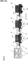
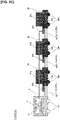
- Figures 3A-3C are schematic views illustrating the state of the combination vehicle when imparting braking force to the towed vehicles 2a-2c, and the brakes 24a-24c to which braking force is imparted are indicated by shading.
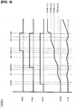
- Figure 4 is a timing chart illustrating the timing with which braking force is imparted to the towed vehicles 2a-2c, and the timing with which the towing vehicle 1 is caused to generate pulling force.
- Figure 4 also illustrates changes in the speed of the towing vehicle 1 due to the expansion of couplers 4a-4c caused by the towing vehicle 1 generating pulling force.
- the braking control device 111 applies a braking force FbC to the towed vehicle 2c located on a rearmost side of the combination vehicle by operation of the brake 24c, as illustrated in Figure 3A .
- the braking force FbC that is applied to the towed vehicle 2c shall be the value shown in formula (1) below (units are N.).
- braking force is imparted to the towed vehicle 2c such that the towed vehicle 2c will not move at the timing of (A) in Figure 4 ; thereafter, the towing vehicle 1 generates a pulling force Ftow to a degree that will accelerate the towed vehicle 2c at the target acceleration a ref , at the timings of (B)-(C) shown in Figure 4 .
- the tensile load that is applied to the coupler 4c which is connected to the towed vehicle 2c, reaches a threshold value N 4c that is set in advance with respect to the coupler 4c (value of the tensile load that is predicted to be applied to the coupler 4c when the combination vehicle is accelerated at the target acceleration a ref ), and the coupler 4c will expand to a length that is equivalent to the case in which the combination vehicle is accelerated at the target acceleration a ref .
- N 4c value of the tensile load that is predicted to be applied to the coupler 4c when the combination vehicle is accelerated at the target acceleration a ref
- the braking control device 111 applies a braking force FbB to the towed vehicle 2b by operation of the brake 24b, as illustrated in Figure 3B .
- the braking force FbB that is applied to the towed vehicle 2b shall be the value shown in formula (3) below.
- braking force is imparted to the towed vehicle 2b such that the towed vehicle 2b will not move at the timing of (E) in Figure 4 ; thereafter, the pulling force Ftow of the towing vehicle 1 is increased to a degree at which it is possible to accelerate the towed vehicle 2c and the towed vehicle 2b at the target acceleration a ref , at the timings of (F)-(G) shown in Figure 4 .
- the tensile load that is applied to the coupler 4b which is connected to the towed vehicle 2b, reaches a threshold value N 4b that is set in advance with respect to the coupler 4b (value of the tensile load that is predicted to be applied to the coupler 4b when the combination vehicle is accelerated at the target acceleration a ref ), and the coupler 4b will expand to a length that is equivalent to the case in which the combination vehicle is accelerated at the target acceleration a ref .
- N 4b value of the tensile load that is predicted to be applied to the coupler 4b when the combination vehicle is accelerated at the target acceleration a ref
- the braking control device 111 applies a braking force FbA to the towed vehicle 2a by operation of the brake 24a, as illustrated in Figure 3C .
- the braking force FbA that is applied to the towed vehicle 2a shall be the value shown in formula (5) below.
- braking force is imparted to the towed vehicle 2a such that the towed vehicle 2a will not move at the timing of (I) in Figure 4 ; thereafter, the pulling force Ftow of the towing vehicle 1 is increased to a degree with which it is possible to accelerate the towed vehicles 2a-2c at the target acceleration a ref , at the timings of (J)-(K) shown in Figure 4 .
- the tensile load that is applied to the coupler 4a which is connected to the towed vehicle 2a, reaches a threshold value N 4a that is set in advance with respect to the coupler 4a (value of the tensile load that is predicted to be applied to the coupler 4a when the combination vehicle is accelerated at the target acceleration a ref ), and the coupler 4a will expand to a length that is equivalent to the case in which the combination vehicle is accelerated at the target acceleration a ref .
- N 4a value of the tensile load that is predicted to be applied to the coupler 4a when the combination vehicle is accelerated at the target acceleration a ref
- the coupler 4a will expand to a length that is equivalent to the case in which the combination vehicle is accelerated at the target acceleration a ref .
- the towing vehicle 1 moves forward due to the elongation of the coupler 4a, and the speed V increases slightly. Thereafter, since the expansion of the coupler 4a stops, the speed of the towing vehicle 1 decreases during the period between
- ⁇ tow is the coefficient of rolling resistance of the wheels of the towing vehicle 1
- Mtow is the total weight of the towing vehicle 1.
- a predetermined braking force is sequentially imparted to the towed vehicles 2a-2c before the combination vehicle is started, while increasing the pulling force of the towing vehicle 1 in a stepwise manner.
- the tensile loads that are applied to the couplers 4a-4c of the combination vehicle are configured to respectively reach predetermined threshold values, which are set for each coupler, in a state in which the pulling force of the towing vehicle 1 and the braking forces of the towed vehicles 2a-2c are in a balanced state (that is, applying larger braking forces to the towed vehicles 2a-2c, as the tensile loads that will be applied to the couplers 4a-4c by the pulling force of the towing vehicle 1 are increased).
- the expansion amount of the couplers 4a-4c can be made equal to the case in which the combination vehicle is accelerated at the target acceleration a ref . Therefore, in the present embodiment, the couplers 4a-4c will be appropriately elongated before the combination vehicle is actually started, and by further increasing the pulling force of the towed vehicle 1 in this state to actually start the combination vehicle, it is possible to appropriately suppress shocks and vibrations of the towed vehicles 2a-2c, which are caused by expansion and contraction of the couplers 4a-4c when the combination vehicle is started.
- braking force is imparted in order from the towed vehicle that is located on the rear side of the combination vehicle, that is, in the order of the towed vehicle 2c, the towed vehicle 2b, and the towed vehicle 2a; however, the order in which braking force is imparted is not limited to this example.
- the number of towed vehicles to which braking force is imparted is also not particularly limited, and it is sufficient if braking force is applied to at least one towed vehicle.
- braking force may be imparted to only two towed vehicles, the towed vehicle 2b and the towed vehicle 2a, in the order of the towed vehicle 2b and the towed vehicle 2a.
- the coupler 4b connected to the towed vehicle 2b, and the coupler 4a connected to the towed vehicle 2a will be elongated.
- braking force may be imparted only to the towed vehicle 2c. In this case, the coupler 4c connected to the towed vehicle 2c will be elongated.
- the combination vehicle when stopping a combination vehicle that has started and is traveling to a desired location, the combination vehicle may be stopped in front of the target stopping location, which is set in advance, in preparation for the next departure.
- the target stopping location which is set in advance, in preparation for the next departure.
- the brakes 24a-24c of the towed vehicles 2a-2c correspond to the brake device of the present invention
- the braking control device 111 of the towing vehicle 1 corresponds to the braking control device of the present invention
Landscapes
- Engineering & Computer Science (AREA)
- Mechanical Engineering (AREA)
- Transportation (AREA)
- Power Engineering (AREA)
- Regulating Braking Force (AREA)
- Braking Systems And Boosters (AREA)
Claims (6)
- Verfahren zum Steuern einer Bremsvorrichtung, die eine Bremskraft von Anhängefahrzeugen (2a, 2b, 2c) in einem Kombinationsfahrzeug steuert, das ein Zugfahrzeug (1) und mehrere der Anhängefahrzeuge (2a, 2b, 2c) aufweist, die durch das Zugfahrzeug (1) geschleppt werden, und in dem eine Kopplung zwischen dem Zugfahrzeug (1) und einem Anhängefahrzeug (2a) und eine Kopplung zwischen den Anhängefahrzeugen (2a, 2b, 2c) durch Kupplungen (4a, 4b, 4c) ausgeführt werden,
gekennzeichnet durch
nachdem bewirkt worden ist, dass sich das Anhängefahrzeug (2c) nicht bewegt, das auf der hintersten Seite angeordnet ist, Übermitteln einer Bremskraft auf die mehreren Anhängefahrzeuge (2a, 2b, 2c), die durch das Zugfahrzeug (1) geschleppt werden, in der Reihenfolge des Anhängefahrzeugs von einer Rückseite. - Verfahren zum Steuern der Bremsvorrichtung nach Anspruch 1, das ferner das Lösen aller Bremskräfte aufweist, die auf die Anhängefahrzeuge (2a, 2b, 2c) übermittelt werden, wenn Zugbelastungen, die auf die Kupplungen (4a, 4b, 4c) ausgeübt werden, die jeweilige der Anhängefahrzeuge (2a, 2b, 2c) verbinden, vorgegebene Schwellenwerte erreichen, die im Voraus für jede der Kupplungen festgelegt worden sind, nachdem auf mindesten ein Anhängefahrzeug (2a, 2b, 2c) eine Bremskraft übermittelt wird.
- Verfahren zum Steuern der Bremsvorrichtung nach einem der Ansprüche 1 bis 2, wobei die Anwendung der Bremskraft auf die Anhängefahrzeuge (2a, 2b, 2c) ausgeführt wird, während die Anhängefahrzeuge (2a, 2b, 2c) angehalten werden.
- Verfahren zum Steuern der Bremsvorrichtung nach einem der Ansprüche 1 bis 3, wobei das Übermitteln der Bremskraft auf die Anhängefahrzeuge (2a, 2b, 2c) so ausgeführt wird, dass beim Anhalten des Zugfahrzeugs (1), das sich bewegt, das Kombinationsfahrzeug vor einem Zielanhalteort angehalten wird, im Voraus festgelegt wird.
- Verfahren zum Steuern der Bremsvorrichtung nach einem der Ansprüche 1 bis 4, wobei eine größere Bremskraft auf die Anhängefahrzeuge (2a, 2b, 2c) übermittelt wird, die mit den Kupplungen (4a, 4b, 4c) verbunden sind, wenn die Zugbelastungen erhöht werden, die auf die Kupplungen (4a, 4b, 4c) ausgeübt werden.
- Bremssteuervorrichtung zum Steuern einer Bremsvorrichtung, die eine Bremskraft von Anhängefahrzeugen (2a, 2b, 2c) in einem Kombinationsfahrzeug steuert, das ein Zugfahrzeug (1) und mehrere der Anhängefahrzeuge (2a, 2b, 2c) aufweist, die durch das Zugfahrzeug (1) geschleppt werden, und in dem eine Kopplung zwischen dem Zugfahrzeug (1) und einem Anhängefahrzeug (2a) und eine Kopplung zwischen den Anhängefahrzeugen (2a, 2b, 2c) durch Kupplungen (4a, 4b, 4c) ausgeführt werden,
dadurch gekennzeichnet, dass
die Bremssteuervorrichtung konfiguriert ist, nachdem bewirkt worden ist, dass sich das Anhängefahrzeug (2c) nicht bewegt, das auf der hintersten Seite angeordnet ist, eine Bremskraft auf die mehreren Anhängefahrzeuge (2a, 2b, 2c), die durch das Zugfahrzeug (1) geschleppt werden, ausgehend in der Reihenfolge vom Anhängefahrzeug zu übermitteln, das auf der Rückseite angeordnet ist.
Applications Claiming Priority (1)
| Application Number | Priority Date | Filing Date | Title |
|---|---|---|---|
| PCT/JP2015/069908 WO2017009899A1 (ja) | 2015-07-10 | 2015-07-10 | 制動装置の制御方法及び制動制御装置 |
Publications (3)
| Publication Number | Publication Date |
|---|---|
| EP3321143A1 EP3321143A1 (de) | 2018-05-16 |
| EP3321143A4 EP3321143A4 (de) | 2018-08-29 |
| EP3321143B1 true EP3321143B1 (de) | 2019-07-10 |
Family
ID=57757094
Family Applications (1)
| Application Number | Title | Priority Date | Filing Date |
|---|---|---|---|
| EP15898215.7A Active EP3321143B1 (de) | 2015-07-10 | 2015-07-10 | Verfahren zur steuerung einer bremsvorrichtung und bremssteuerungsvorrichtung |
Country Status (10)
| Country | Link |
|---|---|
| US (1) | US10442412B2 (de) |
| EP (1) | EP3321143B1 (de) |
| JP (1) | JP6497441B2 (de) |
| KR (1) | KR101888340B1 (de) |
| CN (1) | CN107848503B (de) |
| BR (1) | BR112018000295B1 (de) |
| CA (1) | CA2991874C (de) |
| MX (1) | MX364034B (de) |
| RU (1) | RU2669495C1 (de) |
| WO (1) | WO2017009899A1 (de) |
Families Citing this family (1)
| Publication number | Priority date | Publication date | Assignee | Title |
|---|---|---|---|---|
| GB2620183B (en) * | 2022-06-30 | 2024-10-09 | Bamford Excavators Ltd | A method and system for enhanced braking in a tractor unit |
Family Cites Families (12)
| Publication number | Priority date | Publication date | Assignee | Title |
|---|---|---|---|---|
| SU74067A1 (ru) * | 1947-06-20 | 1948-11-30 | И.Н. Новиков | Поглощающий пружинно-фрикционный аппарат дл железнодорожных вагонов |
| SU86756A1 (ru) * | 1948-12-20 | 1949-11-30 | И.Д. Сизов | Устройство дл перераспределени нагрузок между сцепными и поддерживающими ос ми локомотива |
| CA2041158C (en) * | 1991-04-24 | 1994-09-20 | Edwin R. Wagner | Tow hook activated brake release method and apparatus |
| JP3620906B2 (ja) | 1995-11-14 | 2005-02-16 | 日産ディーゼル工業株式会社 | 連結車の制動装置 |
| US5833325A (en) * | 1996-02-06 | 1998-11-10 | Westinghouse Air Brake Company | Freight brake control using train net braking ratio |
| ZA966436B (en) | 1996-04-15 | 1998-01-22 | Westinghouse Air Brake Co | Selectable grade and uniform net shoe force braking for railway freight vehicle. |
| FR2774343B1 (fr) | 1998-01-30 | 2000-03-31 | Sab Wabco Sa | Procede de telecommande de distributeurs de freinage et distributeurs pour la mise en oeuvre de ce procede |
| US6273521B1 (en) * | 1998-07-31 | 2001-08-14 | Westinghouse Air Brake Technologies Corporation | Electronic air brake control system for railcars |
| JP2004049000A (ja) | 2003-11-06 | 2004-02-12 | Toshiba Transport Eng Inc | 電気車制御装置 |
| JP2010259282A (ja) | 2009-04-28 | 2010-11-11 | Toshiba Corp | 機関車制御装置,機関車制御システム及び機関車の発進制御方法 |
| CN103661337A (zh) * | 2012-09-05 | 2014-03-26 | 卡特彼勒公司 | 释放抛锚机器驻车制动器的方法和系统及含该系统的机器 |
| CN204150058U (zh) | 2014-10-30 | 2015-02-11 | 株洲时代新材料科技股份有限公司 | 一种可自动调整刚度的低地板车弹性铰接装置 |
-
2015
- 2015-07-10 MX MX2018000326A patent/MX364034B/es active IP Right Grant
- 2015-07-10 EP EP15898215.7A patent/EP3321143B1/de active Active
- 2015-07-10 CN CN201580081613.5A patent/CN107848503B/zh active Active
- 2015-07-10 KR KR1020187002884A patent/KR101888340B1/ko active Active
- 2015-07-10 CA CA2991874A patent/CA2991874C/en active Active
- 2015-07-10 BR BR112018000295-0A patent/BR112018000295B1/pt active IP Right Grant
- 2015-07-10 RU RU2018104976A patent/RU2669495C1/ru active
- 2015-07-10 US US15/740,380 patent/US10442412B2/en active Active
- 2015-07-10 JP JP2017528011A patent/JP6497441B2/ja active Active
- 2015-07-10 WO PCT/JP2015/069908 patent/WO2017009899A1/ja not_active Ceased
Non-Patent Citations (1)
| Title |
|---|
| None * |
Also Published As
| Publication number | Publication date |
|---|---|
| CA2991874C (en) | 2018-08-21 |
| MX364034B (es) | 2019-04-11 |
| BR112018000295B1 (pt) | 2022-12-06 |
| KR20180017206A (ko) | 2018-02-20 |
| MX2018000326A (es) | 2018-03-14 |
| US10442412B2 (en) | 2019-10-15 |
| US20180186348A1 (en) | 2018-07-05 |
| CN107848503B (zh) | 2019-04-19 |
| CA2991874A1 (en) | 2017-01-19 |
| EP3321143A4 (de) | 2018-08-29 |
| EP3321143A1 (de) | 2018-05-16 |
| JPWO2017009899A1 (ja) | 2018-04-26 |
| WO2017009899A1 (ja) | 2017-01-19 |
| JP6497441B2 (ja) | 2019-04-10 |
| RU2669495C1 (ru) | 2018-10-11 |
| KR101888340B1 (ko) | 2018-08-13 |
| CN107848503A (zh) | 2018-03-27 |
| BR112018000295A2 (pt) | 2018-09-04 |
Similar Documents
| Publication | Publication Date | Title |
|---|---|---|
| EP4090561B1 (de) | Verfahren zum in gang setzen eines schwerlastfahrzeugs | |
| US10128780B2 (en) | Method and system for controlling the regenerative braking of a vehicle | |
| JP6752877B2 (ja) | 車両を制動する方法 | |
| US8746419B2 (en) | Method for operating a braking system, braking system and motor vehicle having a braking system | |
| DE102009047612A1 (de) | Verfahren zum Bremsen eines Fahrzeugs mit einem elektrischen Antriebsmotor | |
| DE102017204636A1 (de) | Verfahren und Vorrichtung zum ruckfreien Anhalten eines Kraftfahrzeugs | |
| DE102011114703B4 (de) | Verfahren und System zur Steuerung einer Antriebsstrangstabilität für ein Fahrzeug | |
| EP3321143A1 (de) | Verfahren zur steuerung einer bremsvorrichtung und bremssteuerungsvorrichtung | |
| CN109760685A (zh) | 用于运行机动车的方法和机动车 | |
| US20170101085A1 (en) | Driving control method for hybrid vehicles | |
| DE102013226894A1 (de) | Verfahren zur Vermeidung von Schwingungen im Antriebsstrang eines Kraftfahrzeugs mit Elektroantrieb | |
| DE102013204913A1 (de) | Rekuperation im Anhängerbetrieb | |
| US11453389B2 (en) | Vehicle equipped with electric motor and parking control method therefor | |
| DE102015015697A1 (de) | Verfahren zur Ansteuerung einer elektrischen Maschine für den Antrieb eines Kraftfahrzeugs und Kraftfahrzeug | |
| DE102013221535A1 (de) | E-Maschinen-Schleppmomentenkompensation | |
| DE102015225041A1 (de) | Verfahren zum Lösen einer elektromotorisch aktuierten, ersten Bremseinrichtung, Steuergerät für ein Bremssystem eines Fahrzeugs, Bremssystem für ein Fahrzeug, und Fahrzeug mit einem solchen Bremssystem | |
| US7467692B2 (en) | Method of and system for reducing power required for an electric brake to maintain a static force | |
| KR20220017539A (ko) | 전기 모터를 구비한 자동차 및 그를 위한 파킹 기어 해제 방법 | |
| EP3473517B1 (de) | Vorrichtung zur steuerung von schienenfahrzeugbremsen und verfahren zur steuerung von schienenfahrzeugbremsen | |
| DE102017212366A1 (de) | Fahrerassistenzsystem, Fortbewegungsmittel und Verfahren zur Unterstützung eines Anwenders bei der Betätigung eines Bremssystems | |
| DE102012212282A1 (de) | Verfahren zum Abbremsen eines Kraftfahrzeuges mit einem Doppelkupplungsgetriebe | |
| DE102013213145A1 (de) | Verfahren zur Steuerung des Betriebs eines Hybridfahrzeugs | |
| JP2025501860A (ja) | 自動シフトチェンジ制御方法、装置、機器及び記憶媒体 | |
| DE102014212332A1 (de) | Kraftfahrzeug | |
| TH1801002944A (th) | ยานพาหนะแบบไฮบริดและวิธีการควบคุมสำหรับสิ่งดังกล่าว |
Legal Events
| Date | Code | Title | Description |
|---|---|---|---|
| STAA | Information on the status of an ep patent application or granted ep patent |
Free format text: STATUS: THE INTERNATIONAL PUBLICATION HAS BEEN MADE |
|
| PUAI | Public reference made under article 153(3) epc to a published international application that has entered the european phase |
Free format text: ORIGINAL CODE: 0009012 |
|
| STAA | Information on the status of an ep patent application or granted ep patent |
Free format text: STATUS: REQUEST FOR EXAMINATION WAS MADE |
|
| 17P | Request for examination filed |
Effective date: 20180208 |
|
| AK | Designated contracting states |
Kind code of ref document: A1 Designated state(s): AL AT BE BG CH CY CZ DE DK EE ES FI FR GB GR HR HU IE IS IT LI LT LU LV MC MK MT NL NO PL PT RO RS SE SI SK SM TR |
|
| AX | Request for extension of the european patent |
Extension state: BA ME |
|
| A4 | Supplementary search report drawn up and despatched |
Effective date: 20180801 |
|
| RIC1 | Information provided on ipc code assigned before grant |
Ipc: B60T 13/66 20060101ALI20180726BHEP Ipc: B60T 15/46 20060101ALI20180726BHEP Ipc: B60T 7/22 20060101AFI20180726BHEP Ipc: B60T 17/22 20060101ALI20180726BHEP |
|
| DAV | Request for validation of the european patent (deleted) | ||
| DAX | Request for extension of the european patent (deleted) | ||
| GRAP | Despatch of communication of intention to grant a patent |
Free format text: ORIGINAL CODE: EPIDOSNIGR1 |
|
| STAA | Information on the status of an ep patent application or granted ep patent |
Free format text: STATUS: GRANT OF PATENT IS INTENDED |
|
| INTG | Intention to grant announced |
Effective date: 20190329 |
|
| GRAS | Grant fee paid |
Free format text: ORIGINAL CODE: EPIDOSNIGR3 |
|
| GRAA | (expected) grant |
Free format text: ORIGINAL CODE: 0009210 |
|
| STAA | Information on the status of an ep patent application or granted ep patent |
Free format text: STATUS: THE PATENT HAS BEEN GRANTED |
|
| AK | Designated contracting states |
Kind code of ref document: B1 Designated state(s): AL AT BE BG CH CY CZ DE DK EE ES FI FR GB GR HR HU IE IS IT LI LT LU LV MC MK MT NL NO PL PT RO RS SE SI SK SM TR |
|
| REG | Reference to a national code |
Ref country code: GB Ref legal event code: FG4D |
|
| REG | Reference to a national code |
Ref country code: CH Ref legal event code: EP Ref country code: AT Ref legal event code: REF Ref document number: 1153243 Country of ref document: AT Kind code of ref document: T Effective date: 20190715 |
|
| REG | Reference to a national code |
Ref country code: IE Ref legal event code: FG4D |
|
| REG | Reference to a national code |
Ref country code: DE Ref legal event code: R096 Ref document number: 602015033778 Country of ref document: DE |
|
| REG | Reference to a national code |
Ref country code: NL Ref legal event code: MP Effective date: 20190710 |
|
| REG | Reference to a national code |
Ref country code: LT Ref legal event code: MG4D |
|
| REG | Reference to a national code |
Ref country code: AT Ref legal event code: MK05 Ref document number: 1153243 Country of ref document: AT Kind code of ref document: T Effective date: 20190710 |
|
| PG25 | Lapsed in a contracting state [announced via postgrant information from national office to epo] |
Ref country code: HR Free format text: LAPSE BECAUSE OF FAILURE TO SUBMIT A TRANSLATION OF THE DESCRIPTION OR TO PAY THE FEE WITHIN THE PRESCRIBED TIME-LIMIT Effective date: 20190710 Ref country code: PT Free format text: LAPSE BECAUSE OF FAILURE TO SUBMIT A TRANSLATION OF THE DESCRIPTION OR TO PAY THE FEE WITHIN THE PRESCRIBED TIME-LIMIT Effective date: 20191111 Ref country code: NL Free format text: LAPSE BECAUSE OF FAILURE TO SUBMIT A TRANSLATION OF THE DESCRIPTION OR TO PAY THE FEE WITHIN THE PRESCRIBED TIME-LIMIT Effective date: 20190710 Ref country code: LT Free format text: LAPSE BECAUSE OF FAILURE TO SUBMIT A TRANSLATION OF THE DESCRIPTION OR TO PAY THE FEE WITHIN THE PRESCRIBED TIME-LIMIT Effective date: 20190710 Ref country code: AT Free format text: LAPSE BECAUSE OF FAILURE TO SUBMIT A TRANSLATION OF THE DESCRIPTION OR TO PAY THE FEE WITHIN THE PRESCRIBED TIME-LIMIT Effective date: 20190710 Ref country code: NO Free format text: LAPSE BECAUSE OF FAILURE TO SUBMIT A TRANSLATION OF THE DESCRIPTION OR TO PAY THE FEE WITHIN THE PRESCRIBED TIME-LIMIT Effective date: 20191010 Ref country code: BG Free format text: LAPSE BECAUSE OF FAILURE TO SUBMIT A TRANSLATION OF THE DESCRIPTION OR TO PAY THE FEE WITHIN THE PRESCRIBED TIME-LIMIT Effective date: 20191010 Ref country code: FI Free format text: LAPSE BECAUSE OF FAILURE TO SUBMIT A TRANSLATION OF THE DESCRIPTION OR TO PAY THE FEE WITHIN THE PRESCRIBED TIME-LIMIT Effective date: 20190710 Ref country code: SE Free format text: LAPSE BECAUSE OF FAILURE TO SUBMIT A TRANSLATION OF THE DESCRIPTION OR TO PAY THE FEE WITHIN THE PRESCRIBED TIME-LIMIT Effective date: 20190710 |
|
| PG25 | Lapsed in a contracting state [announced via postgrant information from national office to epo] |
Ref country code: RS Free format text: LAPSE BECAUSE OF FAILURE TO SUBMIT A TRANSLATION OF THE DESCRIPTION OR TO PAY THE FEE WITHIN THE PRESCRIBED TIME-LIMIT Effective date: 20190710 Ref country code: LV Free format text: LAPSE BECAUSE OF FAILURE TO SUBMIT A TRANSLATION OF THE DESCRIPTION OR TO PAY THE FEE WITHIN THE PRESCRIBED TIME-LIMIT Effective date: 20190710 Ref country code: GR Free format text: LAPSE BECAUSE OF FAILURE TO SUBMIT A TRANSLATION OF THE DESCRIPTION OR TO PAY THE FEE WITHIN THE PRESCRIBED TIME-LIMIT Effective date: 20191011 Ref country code: IS Free format text: LAPSE BECAUSE OF FAILURE TO SUBMIT A TRANSLATION OF THE DESCRIPTION OR TO PAY THE FEE WITHIN THE PRESCRIBED TIME-LIMIT Effective date: 20191110 Ref country code: AL Free format text: LAPSE BECAUSE OF FAILURE TO SUBMIT A TRANSLATION OF THE DESCRIPTION OR TO PAY THE FEE WITHIN THE PRESCRIBED TIME-LIMIT Effective date: 20190710 Ref country code: ES Free format text: LAPSE BECAUSE OF FAILURE TO SUBMIT A TRANSLATION OF THE DESCRIPTION OR TO PAY THE FEE WITHIN THE PRESCRIBED TIME-LIMIT Effective date: 20190710 |
|
| REG | Reference to a national code |
Ref country code: CH Ref legal event code: PL |
|
| PG25 | Lapsed in a contracting state [announced via postgrant information from national office to epo] |
Ref country code: TR Free format text: LAPSE BECAUSE OF FAILURE TO SUBMIT A TRANSLATION OF THE DESCRIPTION OR TO PAY THE FEE WITHIN THE PRESCRIBED TIME-LIMIT Effective date: 20190710 |
|
| REG | Reference to a national code |
Ref country code: BE Ref legal event code: MM Effective date: 20190731 |
|
| PG25 | Lapsed in a contracting state [announced via postgrant information from national office to epo] |
Ref country code: EE Free format text: LAPSE BECAUSE OF FAILURE TO SUBMIT A TRANSLATION OF THE DESCRIPTION OR TO PAY THE FEE WITHIN THE PRESCRIBED TIME-LIMIT Effective date: 20190710 Ref country code: DK Free format text: LAPSE BECAUSE OF FAILURE TO SUBMIT A TRANSLATION OF THE DESCRIPTION OR TO PAY THE FEE WITHIN THE PRESCRIBED TIME-LIMIT Effective date: 20190710 Ref country code: RO Free format text: LAPSE BECAUSE OF FAILURE TO SUBMIT A TRANSLATION OF THE DESCRIPTION OR TO PAY THE FEE WITHIN THE PRESCRIBED TIME-LIMIT Effective date: 20190710 Ref country code: IT Free format text: LAPSE BECAUSE OF FAILURE TO SUBMIT A TRANSLATION OF THE DESCRIPTION OR TO PAY THE FEE WITHIN THE PRESCRIBED TIME-LIMIT Effective date: 20190710 Ref country code: PL Free format text: LAPSE BECAUSE OF FAILURE TO SUBMIT A TRANSLATION OF THE DESCRIPTION OR TO PAY THE FEE WITHIN THE PRESCRIBED TIME-LIMIT Effective date: 20190710 |
|
| PG25 | Lapsed in a contracting state [announced via postgrant information from national office to epo] |
Ref country code: LI Free format text: LAPSE BECAUSE OF NON-PAYMENT OF DUE FEES Effective date: 20190731 Ref country code: IS Free format text: LAPSE BECAUSE OF FAILURE TO SUBMIT A TRANSLATION OF THE DESCRIPTION OR TO PAY THE FEE WITHIN THE PRESCRIBED TIME-LIMIT Effective date: 20200224 Ref country code: SK Free format text: LAPSE BECAUSE OF FAILURE TO SUBMIT A TRANSLATION OF THE DESCRIPTION OR TO PAY THE FEE WITHIN THE PRESCRIBED TIME-LIMIT Effective date: 20190710 Ref country code: MC Free format text: LAPSE BECAUSE OF FAILURE TO SUBMIT A TRANSLATION OF THE DESCRIPTION OR TO PAY THE FEE WITHIN THE PRESCRIBED TIME-LIMIT Effective date: 20190710 Ref country code: BE Free format text: LAPSE BECAUSE OF NON-PAYMENT OF DUE FEES Effective date: 20190731 Ref country code: CZ Free format text: LAPSE BECAUSE OF FAILURE TO SUBMIT A TRANSLATION OF THE DESCRIPTION OR TO PAY THE FEE WITHIN THE PRESCRIBED TIME-LIMIT Effective date: 20190710 Ref country code: CH Free format text: LAPSE BECAUSE OF NON-PAYMENT OF DUE FEES Effective date: 20190731 Ref country code: SM Free format text: LAPSE BECAUSE OF FAILURE TO SUBMIT A TRANSLATION OF THE DESCRIPTION OR TO PAY THE FEE WITHIN THE PRESCRIBED TIME-LIMIT Effective date: 20190710 Ref country code: LU Free format text: LAPSE BECAUSE OF NON-PAYMENT OF DUE FEES Effective date: 20190710 |
|
| REG | Reference to a national code |
Ref country code: DE Ref legal event code: R097 Ref document number: 602015033778 Country of ref document: DE |
|
| PLBE | No opposition filed within time limit |
Free format text: ORIGINAL CODE: 0009261 |
|
| STAA | Information on the status of an ep patent application or granted ep patent |
Free format text: STATUS: NO OPPOSITION FILED WITHIN TIME LIMIT |
|
| PG2D | Information on lapse in contracting state deleted |
Ref country code: IS |
|
| PG25 | Lapsed in a contracting state [announced via postgrant information from national office to epo] |
Ref country code: IE Free format text: LAPSE BECAUSE OF NON-PAYMENT OF DUE FEES Effective date: 20190710 |
|
| 26N | No opposition filed |
Effective date: 20200603 |
|
| PG25 | Lapsed in a contracting state [announced via postgrant information from national office to epo] |
Ref country code: SI Free format text: LAPSE BECAUSE OF FAILURE TO SUBMIT A TRANSLATION OF THE DESCRIPTION OR TO PAY THE FEE WITHIN THE PRESCRIBED TIME-LIMIT Effective date: 20190710 |
|
| PG25 | Lapsed in a contracting state [announced via postgrant information from national office to epo] |
Ref country code: CY Free format text: LAPSE BECAUSE OF FAILURE TO SUBMIT A TRANSLATION OF THE DESCRIPTION OR TO PAY THE FEE WITHIN THE PRESCRIBED TIME-LIMIT Effective date: 20190710 |
|
| PG25 | Lapsed in a contracting state [announced via postgrant information from national office to epo] |
Ref country code: HU Free format text: LAPSE BECAUSE OF FAILURE TO SUBMIT A TRANSLATION OF THE DESCRIPTION OR TO PAY THE FEE WITHIN THE PRESCRIBED TIME-LIMIT; INVALID AB INITIO Effective date: 20150710 Ref country code: MT Free format text: LAPSE BECAUSE OF FAILURE TO SUBMIT A TRANSLATION OF THE DESCRIPTION OR TO PAY THE FEE WITHIN THE PRESCRIBED TIME-LIMIT Effective date: 20190710 |
|
| PG25 | Lapsed in a contracting state [announced via postgrant information from national office to epo] |
Ref country code: MK Free format text: LAPSE BECAUSE OF FAILURE TO SUBMIT A TRANSLATION OF THE DESCRIPTION OR TO PAY THE FEE WITHIN THE PRESCRIBED TIME-LIMIT Effective date: 20190710 |
|
| PGFP | Annual fee paid to national office [announced via postgrant information from national office to epo] |
Ref country code: GB Payment date: 20250630 Year of fee payment: 11 |
|
| PGFP | Annual fee paid to national office [announced via postgrant information from national office to epo] |
Ref country code: FR Payment date: 20250620 Year of fee payment: 11 |
|
| PGFP | Annual fee paid to national office [announced via postgrant information from national office to epo] |
Ref country code: DE Payment date: 20250620 Year of fee payment: 11 |