EP3320996A1 - Procédé et appareil de fabrication d'un composant de presse - Google Patents
Procédé et appareil de fabrication d'un composant de presse Download PDFInfo
- Publication number
- EP3320996A1 EP3320996A1 EP16821262.9A EP16821262A EP3320996A1 EP 3320996 A1 EP3320996 A1 EP 3320996A1 EP 16821262 A EP16821262 A EP 16821262A EP 3320996 A1 EP3320996 A1 EP 3320996A1
- Authority
- EP
- European Patent Office
- Prior art keywords
- blank
- press component
- top plate
- press
- manufacturing
- Prior art date
- Legal status (The legal status is an assumption and is not a legal conclusion. Google has not performed a legal analysis and makes no representation as to the accuracy of the status listed.)
- Granted
Links
Images


Classifications
-
- B—PERFORMING OPERATIONS; TRANSPORTING
- B21—MECHANICAL METAL-WORKING WITHOUT ESSENTIALLY REMOVING MATERIAL; PUNCHING METAL
- B21D—WORKING OR PROCESSING OF SHEET METAL OR METAL TUBES, RODS OR PROFILES WITHOUT ESSENTIALLY REMOVING MATERIAL; PUNCHING METAL
- B21D22/00—Shaping without cutting, by stamping, spinning, or deep-drawing
- B21D22/20—Deep-drawing
- B21D22/22—Deep-drawing with devices for holding the edge of the blanks
-
- B—PERFORMING OPERATIONS; TRANSPORTING
- B21—MECHANICAL METAL-WORKING WITHOUT ESSENTIALLY REMOVING MATERIAL; PUNCHING METAL
- B21D—WORKING OR PROCESSING OF SHEET METAL OR METAL TUBES, RODS OR PROFILES WITHOUT ESSENTIALLY REMOVING MATERIAL; PUNCHING METAL
- B21D22/00—Shaping without cutting, by stamping, spinning, or deep-drawing
- B21D22/20—Deep-drawing
- B21D22/26—Deep-drawing for making peculiarly, e.g. irregularly, shaped articles
-
- B—PERFORMING OPERATIONS; TRANSPORTING
- B21—MECHANICAL METAL-WORKING WITHOUT ESSENTIALLY REMOVING MATERIAL; PUNCHING METAL
- B21D—WORKING OR PROCESSING OF SHEET METAL OR METAL TUBES, RODS OR PROFILES WITHOUT ESSENTIALLY REMOVING MATERIAL; PUNCHING METAL
- B21D22/00—Shaping without cutting, by stamping, spinning, or deep-drawing
- B21D22/02—Stamping using rigid devices or tools
- B21D22/06—Stamping using rigid devices or tools having relatively-movable die parts
-
- B—PERFORMING OPERATIONS; TRANSPORTING
- B21—MECHANICAL METAL-WORKING WITHOUT ESSENTIALLY REMOVING MATERIAL; PUNCHING METAL
- B21D—WORKING OR PROCESSING OF SHEET METAL OR METAL TUBES, RODS OR PROFILES WITHOUT ESSENTIALLY REMOVING MATERIAL; PUNCHING METAL
- B21D24/00—Special deep-drawing arrangements in, or in connection with, presses
- B21D24/04—Blank holders; Mounting means therefor
-
- B—PERFORMING OPERATIONS; TRANSPORTING
- B21—MECHANICAL METAL-WORKING WITHOUT ESSENTIALLY REMOVING MATERIAL; PUNCHING METAL
- B21D—WORKING OR PROCESSING OF SHEET METAL OR METAL TUBES, RODS OR PROFILES WITHOUT ESSENTIALLY REMOVING MATERIAL; PUNCHING METAL
- B21D53/00—Making other particular articles
- B21D53/88—Making other particular articles other parts for vehicles, e.g. cowlings, mudguards
Definitions
- the present invention relates to a method for manufacturing a press component, and an apparatus for manufacturing a press component.
- the body shell of an automobile has a unit construction structure (monocoque structure).
- a unit construction structure is constituted by a number of framework members and formed panels that are joined together.
- a front pillar, a center pillar, a side sill, a roof rail and a side member are known as framework members.
- a hood ridge, a dash panel, a front floor panel, a rear floor front panel and a rear floor rear panel are known as formed members.
- Framework members that have a closed cross-section such as a front pillar, a center pillar and a side sill are assembled by joining configuration members such as a front pillar reinforcement, a center pillar reinforcement and a side sill outer reinforcement to other configuration members such as an outer panel and an inner panel.
- Figure 14 is an explanatory drawing that illustrates an example of a framework member 1.
- a framework member 1 is assembled by joining configuration members 2, 3, 4 and 5 together by spot welding.
- the configuration member 2 has a substantially hat-shaped cross-sectional shape.
- the substantially hat-shaped cross-sectional shape includes a top plate 2a, a pair of left and right vertical walls 2b and 2b, and flanges 2c and 2c that connect with the vertical walls 2b and 2b.
- the top plate 2a has an inverted L-shaped external shape in plan view as viewed from a direction orthogonal to the top plate 2a.
- a configuration member also exists that has an L-shaped external shape that is opposite to the shape of the aforementioned configuration member 2 illustrated in Figure 14 in plan view.
- a component having the aforementioned L-shaped or inverted L-shaped external shape in plan view is referred to generically as an "L-shaped component".
- the strength and rigidity of the framework member 1 are secured by having an L-shaped component as a constituent element.
- FIG. 15 is an explanatory drawing illustrating an example of a T-shaped component 6.
- a top plate 6a of the T-shaped component 6 has a T-shaped external shape in plan view when viewed from a direction that is orthogonal to the top plate 6a.
- a center pillar reinforcement is known as the T-shaped component 6.
- the T-shaped component 6 has a substantially hat-shaped cross-sectional shape.
- the substantially hat-shaped cross-sectional shape has a top plate 6a, a pair of left and right vertical walls 6b and 6b, and a pair of left and right flanges 6c and 6c.
- a Y-shaped component (refer to Figure 13 that is described later) is known as a modification of the T-shaped component 6.
- a top plate 6a of the Y-shaped component has an external shape that is a Y-shape in the aforementioned plan view.
- the L-shaped component 2, the T-shaped component 6 and the Y-shaped component are referred to generically as "curved component".
- a curved component is usually manufactured by press working by draw forming in order to prevent the occurrence of wrinkling.
- Figures 16(a) and 16(b) are explanatory drawings illustrating an outline of press working by draw forming, in which Figure 16(a) illustrates a state prior to the start of forming, and Figure 16(b) illustrates a state when forming is completed (bottom dead center of forming).
- press working by draw forming is performed on a blank 10 using a die 7, a punch 8 and a blank holder 9 to form an intermediate press component 12.
- Figure 17 is an explanatory drawing illustrating an example of a press component 11 manufactured by press working by draw forming.
- Figure 18 is an explanatory drawing illustrating a blank 10 that is the forming starting material for the press component 11.
- Figure 19 is an explanatory drawing illustrating a wrinkle suppression region 10a of the blank 10.
- Figure 20 is an explanatory drawing illustrating an intermediate press component 12 as it is in a state in which press working has been performed thereon.
- the press component 11 illustrated in Figure 17 is manufactured by press working by draw forming through, for example, the processes (i) to (iv) that are listed hereunder.
- Figure 21 is an explanatory drawing illustrating an example of the state of occurrence of pressing defects (wrinkling and cracking) in the intermediate press component 12.
- Patent Document 1 a patented invention relating to a method that, even when using a blank made from a high tensile strength steel sheet having low ductility, enables press working of a curved component by bending forming with a good yield, and without wrinkling or cracking occurring.
- the method relating to the aforementioned patented invention is also referred to as "free bending method”.
- Figure 22 is an explanatory drawing that partially illustrates an outline of the patented invention disclosed by Patent Document 1.
- the patented invention disclosed by Patent Document 1 manufactures a press component 11 by performing cold or warm press working by bending forming on a blank.
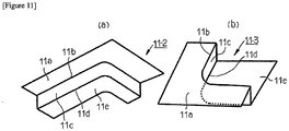
- the press component 11 has a cross-sectional shape (for example, a hat-shaped cross-sectional shape) that includes a top plate 11a, convex ridge lines 11b, 11b, vertical walls 11c, 11c, concave ridge lines 11d, 11d, and flanges 11e, 11e.
- the top plate 11a extends in first direction (direction indicated by an arrow in Figure 17 ).
- the convex ridge lines 11b, 11b are connected to the two ends in the width direction (direction orthogonal to the first direction) of the top plate 11a, respectively.
- the vertical walls 11c, 11c are connected to the convex ridge lines 11b, 11b, respectively.
- the concave ridge lines 11d, 11d are connected to the vertical walls 11c, 11c, respectively.
- the flanges 11e, 11e are connected to the concave ridge lines 11d, 11d, respectively.
- the press component 11 also has a curved portion 13 that curves in a plan view that is orthogonal to the top plate 11a, and by this means the press component 11 has an external shape that is an inverted L-shape.
- a blank 18 is disposed between a die 15 and a die pad 16, and a punch 17 of a press-forming machine 14 that employs bending forming.
- the press component 11 is manufactured by performing press working as described hereunder while suppressing out-of-plane deformation at the portion 18a of the portion at which the top plate 11a is to be formed.
- the inflow amount of the portion of the blank 18 to be formed into the end portion 11f in the extending direction of the top plate 11a that flows into the portion of the blank 18 to be formed into the vertical wall 11c increases.
- a wrinkle suppression region (cutting-off region) that must be provided in the blank 18 when performing the conventional press working by draw forming is not required. Therefore, the yield of the press component 11 improves.
- the free bending method employs press working by bending forming. Therefore, the ductility required for the blank 18 in the free bending method is less than the ductility required for a blank when performing press working by draw forming. Accordingly, it is possible to use a high strength steel sheet with comparatively low ductility as the blank 18, and the sheet thickness of the blank 18 can be set to a small thickness, and thus a reduction in the weight of a vehicle can be achieved.
- Patent Document 2 the present applicants disclosed an invention in which an excess portion of a specific shape is provided at an edge section of a portion to be formed into the flange 11e on the inner circumferential side of the curved portion 13 in a developed blank that is used in the free bending method.
- Patent Document 2 while further enhancing the formability of the vicinity of the curved portion 13 and preventing cracking of the flange 11e on the inner circumferential side of the curved portion 13 by means of the free bending method, excessive inflow of the blank 18 from a portion of the blank 18 to be formed into the top plate 11a to a portion of the blank 18 to be formed into the vertical wall 11c can also be suppressed, and cracking in the end portion of the top plate 11a can also be prevented.
- the present inventors conducted intensive studies to further enhance the formability of the free bending method, and as a result newly found that even when press working is performed on the blank 18 by the free bending methods disclosed in Patent Documents 1 and 2, in some cases the press component 11 cannot be manufactured without defective forming occurring.
- the first case is a case that satisfies at least one of the following conditions:
- An objective of the present invention is to provide a manufacturing method and a manufacturing apparatus for manufacturing a press component, which can manufacture a curved component without generating cracking in a flange on an inner circumferential side of the curved portion even when press working by the free bending method is performed on a blank in the aforementioned first case or second case.
- the present inventors conducted intensive studies to solve the above described problem, and as a result obtained the findings A to D described hereunder to thereby complete the present invention.
- the present invention is as described hereunder.
- a press component 11 to be manufactured by the present invention is an L-shaped component in which a top plate 11a has an external shape that is an inverted L-shape in a plan view that is orthogonal to the top plate 11a is taken an example.
- objects to be manufactured by the present invention are not limited to an L-shaped component, and also include other curved components (T-shaped component and Y-shaped component).
- the press component 11 and an intermediate component 11-1 have a hat-shaped cross-sectional shape constituted by the top plate 11a, two convex ridge lines 11b, 11b, two vertical walls 11c, 11c, two concave ridge lines 11d, 11d and two flanges 11e, 11e is taken as an example.
- objects to be manufactured by the present invention are not limited to the press component 11 and the intermediate component 11-1 that have a hat-shaped cross-sectional shape, and also include intermediate components 11-2 and 11-3 for press components having the cross-sectional shapes shown in Figure 11 set forth below.
- Figure 1 is an explanatory drawing illustrating a configuration example of a manufacturing apparatus 20 according to the present invention.
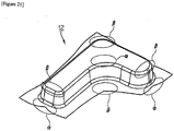
- Figure 2 is an explanatory drawing partially illustrating an example of an intermediate component 11-1 of a press component 11 that was press-formed by the manufacturing apparatus 20.
- the manufacturing apparatus 20 is a press-forming apparatus that employs bending forming and that uses the free bending method.
- the manufacturing apparatus 20 includes a die 21, a die pad 22 and a punch 23.
- the punch 23 is disposed facing the die 21 and the die pad 22.
- the die pad 22 is movable up and down together with the die 21, and can also press a part of a blank 24.
- the manufacturing apparatus 20 manufactures the intermediate component 11-1 of the press component 11 having the external shape illustrated in Figure 2 by performing press working as cold or warm working on the blank (developed blank) 24 or on a blank (not illustrated in the drawings) which was subjected to preforming that is minor processing (for example, embossing) that is disposed between the die 21 and die pad 22 and the punch 23.
- the sheet thickness of the blank 24 is preferably 0.6 to 2.8 mm, more preferably 0.8 to 2.8 mm, and further preferably 1.0 to 2.8 mm.
- the press component 11 or the intermediate component 11-1 has a hat-shaped cross-sectional shape.
- the hat-shaped cross-sectional shape is a shape that includes a top plate 11a, two convex ridge lines 11b, 11b, two vertical walls 11c, 11c, two concave ridge lines 11d, 11d, and two flanges 11e, 11e.
- the press component 11 or the intermediate component 11-1 thereof has a curved portion 13.
- the curved portion 13 curves so that the external shape of the top plate 11a in a plan view orthogonal to the top plate 11a is an inverted L-shaped.
- the top plate 11a extends in a first direction (arrow direction in Figures 2 and 17 ).
- the two convex ridge lines 11b, 11b connect to both end portions in a direction which is orthogonal (that is, the width direction of the top plate 11a) to the first direction of the top plate 11a.
- the two vertical walls 11c, 11c connect to the two convex ridge lines 11b, 11b, respectively.
- the two concave ridge lines 11d, 11d connect to the two vertical walls 11c, 11c, respectively.
- the two flanges 11e, 11e connect to the two concave ridge lines 11d, 11d, respectively.
- the manufacturing apparatus 20 is favorably used in the following first case and second case.
- the die pad 22 presses a portion of the blank 24 to be formed into a part of the top plate 11a at the curved portion 13 of the press component 11 with an applied pressure that is 1.0 MPa or more and less than 32.0 MPa, or comes adjacent to or into contact with the aforementioned portion of the blank 24 while maintaining the distance of a gap with respect to the punch 23 at a distance corresponding to 1.0 to 1.1 times the sheet thickness of the blank 24.
- the intermediate component 11-1 of the press component 11 is manufactured by performing press working that is described hereunder.
- the die 21 and the punch 23 are relatively moved in directions in which the die 21 and the punch 23 approach each other.
- the vertical wall 11c, the concave ridge line 11d and the flange 11e on the inner circumferential side of the curved portion 13 are formed while the portion of the blank 24 to be formed into the end portion 11f is caused to move in-plane (slide) over a portion of the die 22 at which the top plate 11a will be formed.
- Figure 3 is an explanatory drawing illustrating the positional relationship between a material inflow facilitating portion forming mechanism 25 and a concave ridge line forming portion 23b of the manufacturing apparatus 20, and the blank 24.
- a recess 21a and a protrusion 23a as the material inflow facilitating portion forming mechanism 25 for providing a material inflow facilitating portion 19 in the blank 24 are provided in the die 21 and the punch 23, respectively, of the manufacturing apparatus 20.
- the material inflow facilitating portion forming mechanism 25 is constituted by the recess 21a that is provided in the die 21 and the protrusion 23a that is provided in the punch 23.
- the manufacturing apparatus 20 uses the material inflow facilitating portion forming mechanism 25 to provide the material inflow facilitating portion 19 in the vicinity (for example, at only the flange, or at the flange and the concave ridge line) of a portion of the blank 24 to be formed into the flange 11e on the inner circumferential side of the curved portion 13 of the intermediate component 11-1.
- the material inflow facilitating portion forming mechanism 25 provides the material inflow facilitating portion 19 in a region that is outside a region (hatched region in Figure 3 ) of the blank 24 to be formed into the press component 11.
- the material inflow facilitating portion 19 may be provided in a region of the blank 24 (hatched region in Figure 3 ) to be formed into the press component 11.
- Figure 4 is an explanatory drawing illustrating a cross-section in a conventional punch 23-1 in which the material inflow facilitating portion forming mechanism 25 is not provided, that corresponds to a cross-section A-A in Figure 1 .
- Figure 5 is an explanatory drawing illustrating the positional relationship between the blank 24 and the material inflow facilitating portion forming mechanism 25 and concave ridge line forming portion 23b of the manufacturing apparatus 20, and locations of cross-sections B, C and D.
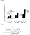
- Figure 6 is a graph illustrating cross-section line length differences (inflow amounts) with respect to a conventional punch at a flange forming portion of the punch 23 at the cross-sections B, C and D.
- the left side illustrates a case according to the conventional method
- the right side illustrates a case according to the method of the present invention.
- the cross-sections below the graph in Figure 6 illustrate the respective shapes of the blank 24 at the cross-sections B, C and D.
- Figure 7 is an explanatory drawing illustrating a cross-section A-A of the punch 23 in which the material inflow facilitating portion forming mechanism 25 is provided.
- the material inflow facilitating portion forming mechanism 25 that is constituted by the recess 21a and the protrusion 23a, the material inflow facilitating portion 19 is provided in the intermediate component 11-1 by press working.
- the cross-sections B, C and D in Figures 5 and 6 are cross-sections in a material inflow direction that is parallel to a straight line that is tangent to a center position (portion "a") of an inner circumference of the curved portion 13 in a plan view orthogonal to the top plate 11a.
- the cross-sections B, C and D are cross-sections in a maximum principal strain direction of a deformation of a portion to be formed into the flange 11e on the inner circumferential side of the curved portion 13.
- the material inflow facilitating portion 19 is provided so that cross-section line lengths at the cross-sections B, C and D gradually increase with distance from the flange 11e on the inner circumferential side of the curved portion 13.
- the cross-sectional shape of the material inflow facilitating portion 19 is not limited to a shape which monotonously increases with distance from the flange 11e on the inner circumferential side of the curved portion 13 of the intermediate component 11-1, and may be a shape that partially includes a portion at which the cross-section line length is constant.
- the material inflow facilitating portion forming mechanism 25 of the method of the present invention is provided so that a cross-section line length difference (inflow amount) relative to the conventional punch of the flange forming portion of the punch 23 increases at each of the cross-sections B, C and D, and so that the cross-section line length difference (inflow amount) at the cross-section C increases more than the cross-section line length difference (inflow amount) at the cross-section B, and the cross-section line length difference (inflow amount) at the cross-section D increases more than the cross-section line length difference (inflow amount) at the cross-section C.
- the material inflow facilitating portion forming mechanism 25 having a shape that increases the cross-section line length difference (inflow amount) at each of the cross-sections B, C and D is provided in the die 21 as the recess 21a and is also provided in the punch 23 as the protrusion 23a.
- the material inflow facilitating portion 19 is exemplified as being provided as a protrusion having an external shape that is obtained by connecting the meeting point of the concave ridge line 11d and the flange 11e of the curved portion 13 that is formed, and an end portion 24a of the blank 24 at the time that forming starts.
- Figure 8 is an explanatory drawing illustrating the positional relationship between the blank 24 and the material inflow facilitating portion forming mechanism 25 and concave ridge line forming portion 23b of the manufacturing apparatus 20, and the locations of cross-sections B, C and D.
- a change differential in the inflow amount of the material that is caused by the material inflow facilitating portion forming mechanism 25 increases with distance from the portion "a" of the blank 24 through the cross-section B, the cross-section C and furthermore the cross-section D as indicated by a broad arrow in Figure 8 .
- Figure 9 is an explanatory drawing that shows the reason why cracking at the portion "a" of the blank 24 is prevented by providing the material inflow facilitating portion forming mechanism 25 that is constituted by the recess 21a and the protrusion 23a, in the die 21 and the punch 23.
- the inflow amount of the blank 24 increases from around the portion "a"
- the inflow amount of the blank 24 to the portion "a” increases. That is, the inflow amount of the blank 24 to the portion of the blank 24 to be formed into the curved portion 13 is increased by means of the material inflow facilitating portion forming mechanism 25.
- the direction of principal strain of a deformation in the portion of the blank 24 to be formed into curved portion 13 does not change significantly, the amount of deformation thereof is reduced.
- the inflow amount of the blank 24 to a portion of the blank 24 to be formed into the flange 11e on the inner circumferential side of the curved portion 13 of the press component 11 increases in comparison to the conventional method in which the material inflow facilitating portion forming mechanism 25 is not provided.
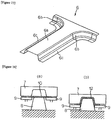
- Figure 10(a) to Figure 10(f) are explanatory drawings that partially illustrate examples of the shape of the protrusion 23a or a recess 23c that are constituent elements of various kinds of the material inflow facilitating portion forming mechanism 25 that is provided in the punch 23.
- a protrusion that is convex toward the same side as the top plate 11a of the press component 11 that was described above referring to Figure 7 can be used as the protrusion 23a that is a constituent element of the material inflow facilitating portion forming mechanism 25 provided in the punch 23.
- the recess 23c that is convex toward the opposite side to the top plate 11a of the press component 11 may be used instead of the protrusion 23a illustrated in Figure 10(a) .
- a protrusion corresponding to the recess 23c is provided in the die 21.
- the protrusion 23a may be provided in a region which is in contact with the blank 24.
- the protrusion 23a as the material inflow facilitating portion 19 may be provided so as to extend over a region (hatched region in Figure 3 ) of the blank 24 to be formed into the press component 11.
- two or more of the protrusions 23a that are independent may be provided as constituent elements of the material inflow facilitating portion forming mechanism 25.
- the protrusion 23a may be provided in a stepped shape in a direction parallel to the sheet thickness direction of the blank 12.
- the material inflow facilitating portion forming mechanism 25 provides one or more of the material inflow facilitating portions 19 that increase an inflow amount by which a portion of the blank 24 to be formed into the end portion 11f of the intermediate component 11-1 flows into a portion of the blank 24 to be formed into the flange 11e on the inner circumferential side of the curved portion 13 of the intermediate component 11-1.
- Figure 11(a) and Figure 11(b) are explanatory drawings that respectively illustrate intermediate components 11-2 and 11-3 of other press components to be manufactured by the present invention.
- the intermediate component 11-1 of the press component 11 is manufactured by the free bending method using the manufacturing apparatus 20.
- the press component 11 that is taken as the manufacturing object of the present invention preferably satisfies the aforementioned first case or second case. This is because, in the press component 11 that satisfies the first case or second case, cracking occurs at the portion "a" of the blank 24 when manufactured by the conventional free bending method.
- a portion (hatched portion 18a in Figure 20 ) of the blank 24 to be formed into a part of the top plate 11a of the curved portion 13 of the press component 11 is pressed with an applied pressure that is 1.0 MPa or more and less than 32.0 MPa by the die pad 22, or while maintaining the distance of a gap between the die pad 22 and the punch 23 at a distance corresponding to 1.0 to 1.1 times the sheet thickness of the blank 24, the die pad 22 is brought adjacent to or into contact with the portion (hatched portion 18a in Figure 20 ) to be formed into the top plate 11a of the curved portion 13 of the press component 11.
- the intermediate component 11-1 of the press component 11 is manufactured by performing press working that is described hereunder.
- the die 21 and the punch 23 are relatively moved in directions in which the die 21 and the punch 23 approach each other.
- the vertical wall 11c, the concave ridge line 11d and the flange 11e on the inner circumferential side of the curved portion 13 are formed while the portion of the blank 24 to be formed into the end portion 11f is caused to move in-plane (slide) over a portion of the die 21 at which the top plate 11a will be formed.
- the material inflow facilitating portion forming mechanism 25 provided in the die 21 and the punch 23 provides at least one material inflow facilitating portion 19 in the vicinity of the portion of the blank 24 to be formed into the flange 11e on the inner circumferential side of the curved portion 13 of the intermediate component 11-1.
- an inflow amount of the blank 24 to a portion of the blank 24 to be formed into the flange 11e on the inner circumferential side of the curved portion 13 of the intermediate component 11-1 increases. Therefore, in the blank 24, the tensile force F in the circumferential direction of the concave ridge line 11d that is located at an upperpart of the portion "a” can be reduced, and by this means cracking at the portion "a" of the blank 24 is prevented.
- the intermediate component 11-1 serves as it is as the press component 11 that is the end product.
- the intermediate component 11-1 is made into the press component 11 by cutting off (trimming) the unwanted part including the material inflow facilitating portion 19 by taking the outer edge portion of the flange 11e as a trim line.
- the L-shaped component 11-1 can be manufactured without generating cracking in the flange 11e on the inner circumferential side of the curved portion 13.
- Table 1 shows a summary of the specifications of the intermediate components 11-1 and the press components that were analyzed as well as the analysis results.
- N o Forming Shape Conditions Maximum Sheet Thickness Reduction Ratio % Material Strength MPa Formed Height mm Top Surface View R 2 mm Concave Ridge Line R 1 mm Without Material Inflow Facilitating Portion (Comparative Example) Cracking Criterion With Material Inflow Facilitating Portion (Example Embodiment of the Present Invention) 1 1180 60 120 20 13 10 8 2 980 80 120 20 16 15 12 3 980 60 120 5 18 15 13 4 980 60 90 20 17 15 10 5 1180 65 150 20 14 10 9 6 1180 50 150 12 12 10 8 7 980 50 130 12 15 15 12 8 980 65 130 20 15 15 11 9 1180 50 130 20 12 10 6 10 980 65 150 12 15 15 10
- the L-shaped component 11-1 can be manufactured without generating cracking in the flange 11e on the inner circumferential side of the curved portion 13.
- an intermediate component 30 (example embodiment of the present invention) of a T-shaped component that is illustrated in Figure 12 and an intermediate component 31 of a Y-shaped component illustrated in Figure 13 that were manufactured using the manufacturing apparatus 20 illustrated in Figure 1
- a maximum sheet thickness reduction ratio at a meeting point "a" portion between a concave ridge line and a flange at a center position in the circumferential direction of a curved portion was analyzed by the finite element method using a computer.
- Table 2 shows a summary of the specifications of the intermediate components 30 and 31 that were analyzed as well as the analysis results for each. Note that, the term "opening angle" in Table 2 refers to an angle 0 shown in Figures 12 and 13 .
- the intermediate component 30 for a T-shaped component and the intermediate component 31 for a Y-shaped component can be manufactured without generating cracking in the flange 11e on the inner circumferential side of the curved portion 13.
Applications Claiming Priority (2)
| Application Number | Priority Date | Filing Date | Title |
|---|---|---|---|
| JP2015135367 | 2015-07-06 | ||
| PCT/JP2016/069009 WO2017006793A1 (fr) | 2015-07-06 | 2016-06-27 | Procédé et appareil de fabrication d'un composant de presse |
Publications (3)
| Publication Number | Publication Date |
|---|---|
| EP3320996A1 true EP3320996A1 (fr) | 2018-05-16 |
| EP3320996A4 EP3320996A4 (fr) | 2019-03-13 |
| EP3320996B1 EP3320996B1 (fr) | 2020-04-01 |
Family
ID=57685485
Family Applications (1)
| Application Number | Title | Priority Date | Filing Date |
|---|---|---|---|
| EP16821262.9A Active EP3320996B1 (fr) | 2015-07-06 | 2016-06-27 | Procédé et appareil de fabrication d'un composant de presse |
Country Status (13)
| Country | Link |
|---|---|
| US (1) | US11020785B2 (fr) |
| EP (1) | EP3320996B1 (fr) |
| JP (1) | JP6119929B1 (fr) |
| KR (1) | KR102015737B1 (fr) |
| CN (1) | CN107848007B (fr) |
| BR (1) | BR112017028380A2 (fr) |
| CA (1) | CA2991565C (fr) |
| ES (1) | ES2796369T3 (fr) |
| MX (1) | MX2018000109A (fr) |
| MY (1) | MY190608A (fr) |
| RU (1) | RU2688976C1 (fr) |
| TW (1) | TWI610733B (fr) |
| WO (1) | WO2017006793A1 (fr) |
Families Citing this family (9)
| Publication number | Priority date | Publication date | Assignee | Title |
|---|---|---|---|---|
| US20180043413A1 (en) * | 2016-08-12 | 2018-02-15 | Uacj Corporation | Press-forming die |
| EP3560618A4 (fr) * | 2016-12-26 | 2020-09-09 | Nippon Steel Corporation | Procédé de mise en forme de tôle métallique, procédé de conception de forme intermédiaire, moule de mise en forme de tôle métallique, programme informatique et support d'enregistrement |
| MX2020005048A (es) | 2017-11-15 | 2020-08-20 | Jfe Steel Corp | Metodo de formacion en prensa de material laminar. |
| US11383286B2 (en) | 2018-02-28 | 2022-07-12 | Jfe Steel Corporation | Metal sheet for press forming, press forming device, and production method for pressed component |
| US11311925B2 (en) * | 2018-05-11 | 2022-04-26 | Nippon Steel Corporation | Saddle-shaped press-molded article manufacturing method, pressing apparatus, and manufacturing method to manufacture saddle-shaped press-molded article |
| JP7110737B2 (ja) * | 2018-06-04 | 2022-08-02 | マツダ株式会社 | プレス成形方法及びプレス成形装置 |
| CN112020399A (zh) * | 2018-07-02 | 2020-12-01 | 惠普发展公司,有限责任合伙企业 | 具有金属流接收特征部的冲压部分 |
| JP6677289B1 (ja) | 2018-12-12 | 2020-04-08 | Jfeスチール株式会社 | プレス成形方法 |
| CN114728322A (zh) * | 2019-09-25 | 2022-07-08 | 日本制铁株式会社 | 构造构件、构造构件制造方法及构造构件制造装置 |
Family Cites Families (17)
| Publication number | Priority date | Publication date | Assignee | Title |
|---|---|---|---|---|
| SU776712A1 (ru) | 1979-01-05 | 1980-11-07 | Московский авиационный технологический институт им.К.Э.Циолковского | Штамп дл выт жки с подпором фланца заготовки |
| SU1329868A1 (ru) | 1984-05-11 | 1987-08-15 | Предприятие П/Я В-2453 | Способ выт жки изделий и штамп дл его осуществлени |
| JP2551022B2 (ja) * | 1987-09-04 | 1996-11-06 | トヨタ自動車株式会社 | 絞り加工方法とそのためのプレス型 |
| RU2057606C1 (ru) * | 1992-10-20 | 1996-04-10 | Челябинский государственный технический университет | Способ изготовления профилей |
| JP2731497B2 (ja) * | 1993-01-22 | 1998-03-25 | 本田技研工業株式会社 | 集合ブランク部材の成形方法および装置 |
| JP3839290B2 (ja) | 2001-09-27 | 2006-11-01 | 株式会社神戸製鋼所 | 金属板の曲げ成形方法 |
| JP4264054B2 (ja) | 2004-06-01 | 2009-05-13 | 株式会社神戸製鋼所 | 曲げ成形方法およびその成形方法に用いる成形金型 |
| JP4853007B2 (ja) * | 2004-12-27 | 2012-01-11 | 日産自動車株式会社 | プレス成形型 |
| JP5194982B2 (ja) * | 2008-04-15 | 2013-05-08 | 新日鐵住金株式会社 | 形状凍結性に優れたプレス成形方法およびその装置 |
| JP2011050971A (ja) * | 2009-08-31 | 2011-03-17 | Jfe Steel Corp | 鋼板の熱間プレス成形方法 |
| MX349143B (es) * | 2010-05-19 | 2017-07-14 | Nippon Steel & Sumitomo Metal Corp | Método para estampar componentes en forma de l. |
| EP2644293B1 (fr) | 2010-11-24 | 2016-07-27 | Nippon Steel & Sumitomo Metal Corporation | Procédé pour fabriquer un produit en forme de l |
| JP5510533B1 (ja) | 2012-12-17 | 2014-06-04 | Jfeスチール株式会社 | プレス成形方法 |
| CN104918727A (zh) * | 2012-12-26 | 2015-09-16 | 日产自动车株式会社 | 拉深成型方法 |
| CN105188982B (zh) | 2013-05-13 | 2018-01-19 | 新日铁住金株式会社 | 坯料、成型板、冲压成型品的制造方法以及冲压成型品 |
| WO2015115348A1 (fr) * | 2014-01-28 | 2015-08-06 | Jfeスチール株式会社 | Procédé de moulage par compression, procédé de fabrication d'un composant moulé par compression et procédé permettant de déterminer une forme de préforme destinée à être utilisée dans lesdits procédés |
| CN204035335U (zh) | 2014-06-17 | 2014-12-24 | 奇瑞汽车股份有限公司 | 一种汽车侧围板冲压模 |
-
2016
- 2016-06-27 JP JP2016563014A patent/JP6119929B1/ja active Active
- 2016-06-27 KR KR1020187003497A patent/KR102015737B1/ko active IP Right Grant
- 2016-06-27 CA CA2991565A patent/CA2991565C/fr active Active
- 2016-06-27 RU RU2018104275A patent/RU2688976C1/ru active
- 2016-06-27 ES ES16821262T patent/ES2796369T3/es active Active
- 2016-06-27 EP EP16821262.9A patent/EP3320996B1/fr active Active
- 2016-06-27 MY MYPI2018700012A patent/MY190608A/en unknown
- 2016-06-27 WO PCT/JP2016/069009 patent/WO2017006793A1/fr active Application Filing
- 2016-06-27 MX MX2018000109A patent/MX2018000109A/es unknown
- 2016-06-27 US US15/741,345 patent/US11020785B2/en active Active
- 2016-06-27 BR BR112017028380-8A patent/BR112017028380A2/pt active Search and Examination
- 2016-06-27 TW TW105120272A patent/TWI610733B/zh not_active IP Right Cessation
- 2016-06-27 CN CN201680040051.4A patent/CN107848007B/zh active Active
Also Published As
| Publication number | Publication date |
|---|---|
| TWI610733B (zh) | 2018-01-11 |
| US11020785B2 (en) | 2021-06-01 |
| BR112017028380A2 (pt) | 2018-08-28 |
| US20180185899A1 (en) | 2018-07-05 |
| EP3320996B1 (fr) | 2020-04-01 |
| TW201707809A (zh) | 2017-03-01 |
| WO2017006793A1 (fr) | 2017-01-12 |
| RU2688976C1 (ru) | 2019-05-23 |
| KR102015737B1 (ko) | 2019-08-28 |
| MX2018000109A (es) | 2018-03-22 |
| KR20180027547A (ko) | 2018-03-14 |
| JPWO2017006793A1 (ja) | 2017-07-06 |
| CA2991565A1 (fr) | 2017-01-12 |
| CA2991565C (fr) | 2020-03-10 |
| CN107848007A (zh) | 2018-03-27 |
| JP6119929B1 (ja) | 2017-04-26 |
| MY190608A (en) | 2022-04-27 |
| EP3320996A4 (fr) | 2019-03-13 |
| ES2796369T3 (es) | 2020-11-26 |
| CN107848007B (zh) | 2019-05-21 |
Similar Documents
| Publication | Publication Date | Title |
|---|---|---|
| EP3320996B1 (fr) | Procédé et appareil de fabrication d'un composant de presse | |
| US9839954B2 (en) | Method for producing center pillar reinforcement | |
| EP2896467B1 (fr) | Procédé de fabrication de composant courbé | |
| EP3272438B1 (fr) | Procédé permettant de produire un produit moulé à la presse, produit moulé à la presse et dispositif de pressage | |
| KR101854511B1 (ko) | 블랭크, 성형판, 프레스 성형품의 제조 방법 및 프레스 성형품 | |
| EP2644293B1 (fr) | Procédé pour fabriquer un produit en forme de l | |
| CN109414745B (zh) | 冲压部件的制造方法及制造装置 | |
| TWI448338B (zh) | 具有l字狀形狀之零件的壓製成形方法 | |
| KR102138043B1 (ko) | 블랭크 및 프레스 성형품의 제조 방법 | |
| CN111727089B (zh) | 冲压部件的制造方法、冲压成型装置和冲压成型用的金属板 | |
| WO2016171229A1 (fr) | Procédé permettant de produire un produit moulé à la presse, produit moulé à la presse et dispositif de pressage | |
| EP3666409B1 (fr) | Procédé de fabrication d'un article moulé à la presse | |
| EP3895824B1 (fr) | Procédé de formage à la presse | |
| WO2023153034A1 (fr) | Procédé de moulage à la presse et procédé de fabrication d'un article moulé à la presse | |
| JP7476935B2 (ja) | プレス成形品の製造方法 | |
| JP5459183B2 (ja) | 金属製車両用クロスメンバー |
Legal Events
| Date | Code | Title | Description |
|---|---|---|---|
| STAA | Information on the status of an ep patent application or granted ep patent |
Free format text: STATUS: THE INTERNATIONAL PUBLICATION HAS BEEN MADE |
|
| PUAI | Public reference made under article 153(3) epc to a published international application that has entered the european phase |
Free format text: ORIGINAL CODE: 0009012 |
|
| STAA | Information on the status of an ep patent application or granted ep patent |
Free format text: STATUS: REQUEST FOR EXAMINATION WAS MADE |
|
| 17P | Request for examination filed |
Effective date: 20180206 |
|
| AK | Designated contracting states |
Kind code of ref document: A1 Designated state(s): AL AT BE BG CH CY CZ DE DK EE ES FI FR GB GR HR HU IE IS IT LI LT LU LV MC MK MT NL NO PL PT RO RS SE SI SK SM TR |
|
| AX | Request for extension of the european patent |
Extension state: BA ME |
|
| DAV | Request for validation of the european patent (deleted) | ||
| DAX | Request for extension of the european patent (deleted) | ||
| A4 | Supplementary search report drawn up and despatched |
Effective date: 20190211 |
|
| RIC1 | Information provided on ipc code assigned before grant |
Ipc: B21D 22/26 20060101AFI20190205BHEP Ipc: B21D 24/04 20060101ALI20190205BHEP Ipc: B21D 24/00 20060101ALI20190205BHEP Ipc: B21D 22/02 20060101ALI20190205BHEP Ipc: B21D 53/88 20060101ALN20190205BHEP Ipc: B21D 22/22 20060101ALI20190205BHEP |
|
| RAP1 | Party data changed (applicant data changed or rights of an application transferred) |
Owner name: NIPPON STEEL CORPORATION |
|
| GRAP | Despatch of communication of intention to grant a patent |
Free format text: ORIGINAL CODE: EPIDOSNIGR1 |
|
| STAA | Information on the status of an ep patent application or granted ep patent |
Free format text: STATUS: GRANT OF PATENT IS INTENDED |
|
| RIC1 | Information provided on ipc code assigned before grant |
Ipc: B21D 22/26 20060101AFI20191121BHEP Ipc: B21D 24/04 20060101ALI20191121BHEP Ipc: B21D 53/88 20060101ALN20191121BHEP Ipc: B21D 22/02 20060101ALI20191121BHEP Ipc: B21D 24/00 20060101ALI20191121BHEP Ipc: B21D 22/22 20060101ALI20191121BHEP |
|
| INTG | Intention to grant announced |
Effective date: 20191211 |
|
| GRAS | Grant fee paid |
Free format text: ORIGINAL CODE: EPIDOSNIGR3 |
|
| GRAA | (expected) grant |
Free format text: ORIGINAL CODE: 0009210 |
|
| STAA | Information on the status of an ep patent application or granted ep patent |
Free format text: STATUS: THE PATENT HAS BEEN GRANTED |
|
| AK | Designated contracting states |
Kind code of ref document: B1 Designated state(s): AL AT BE BG CH CY CZ DE DK EE ES FI FR GB GR HR HU IE IS IT LI LT LU LV MC MK MT NL NO PL PT RO RS SE SI SK SM TR |
|
| REG | Reference to a national code |
Ref country code: GB Ref legal event code: FG4D |
|
| REG | Reference to a national code |
Ref country code: CH Ref legal event code: EP Ref country code: AT Ref legal event code: REF Ref document number: 1250714 Country of ref document: AT Kind code of ref document: T Effective date: 20200415 |
|
| REG | Reference to a national code |
Ref country code: DE Ref legal event code: R096 Ref document number: 602016033221 Country of ref document: DE |
|
| REG | Reference to a national code |
Ref country code: IE Ref legal event code: FG4D |
|
| PGFP | Annual fee paid to national office [announced via postgrant information from national office to epo] |
Ref country code: TR Payment date: 20200625 Year of fee payment: 5 |
|
| PG25 | Lapsed in a contracting state [announced via postgrant information from national office to epo] |
Ref country code: BG Free format text: LAPSE BECAUSE OF FAILURE TO SUBMIT A TRANSLATION OF THE DESCRIPTION OR TO PAY THE FEE WITHIN THE PRESCRIBED TIME-LIMIT Effective date: 20200701 |
|
| REG | Reference to a national code |
Ref country code: NL Ref legal event code: MP Effective date: 20200401 |
|
| REG | Reference to a national code |
Ref country code: LT Ref legal event code: MG4D |
|
| PG25 | Lapsed in a contracting state [announced via postgrant information from national office to epo] |
Ref country code: SE Free format text: LAPSE BECAUSE OF FAILURE TO SUBMIT A TRANSLATION OF THE DESCRIPTION OR TO PAY THE FEE WITHIN THE PRESCRIBED TIME-LIMIT Effective date: 20200401 Ref country code: FI Free format text: LAPSE BECAUSE OF FAILURE TO SUBMIT A TRANSLATION OF THE DESCRIPTION OR TO PAY THE FEE WITHIN THE PRESCRIBED TIME-LIMIT Effective date: 20200401 Ref country code: GR Free format text: LAPSE BECAUSE OF FAILURE TO SUBMIT A TRANSLATION OF THE DESCRIPTION OR TO PAY THE FEE WITHIN THE PRESCRIBED TIME-LIMIT Effective date: 20200702 Ref country code: PT Free format text: LAPSE BECAUSE OF FAILURE TO SUBMIT A TRANSLATION OF THE DESCRIPTION OR TO PAY THE FEE WITHIN THE PRESCRIBED TIME-LIMIT Effective date: 20200817 Ref country code: IS Free format text: LAPSE BECAUSE OF FAILURE TO SUBMIT A TRANSLATION OF THE DESCRIPTION OR TO PAY THE FEE WITHIN THE PRESCRIBED TIME-LIMIT Effective date: 20200801 Ref country code: NO Free format text: LAPSE BECAUSE OF FAILURE TO SUBMIT A TRANSLATION OF THE DESCRIPTION OR TO PAY THE FEE WITHIN THE PRESCRIBED TIME-LIMIT Effective date: 20200701 Ref country code: LT Free format text: LAPSE BECAUSE OF FAILURE TO SUBMIT A TRANSLATION OF THE DESCRIPTION OR TO PAY THE FEE WITHIN THE PRESCRIBED TIME-LIMIT Effective date: 20200401 Ref country code: NL Free format text: LAPSE BECAUSE OF FAILURE TO SUBMIT A TRANSLATION OF THE DESCRIPTION OR TO PAY THE FEE WITHIN THE PRESCRIBED TIME-LIMIT Effective date: 20200401 |
|
| REG | Reference to a national code |
Ref country code: AT Ref legal event code: MK05 Ref document number: 1250714 Country of ref document: AT Kind code of ref document: T Effective date: 20200401 |
|
| REG | Reference to a national code |
Ref country code: ES Ref legal event code: FG2A Ref document number: 2796369 Country of ref document: ES Kind code of ref document: T3 Effective date: 20201126 |
|
| PG25 | Lapsed in a contracting state [announced via postgrant information from national office to epo] |
Ref country code: LV Free format text: LAPSE BECAUSE OF FAILURE TO SUBMIT A TRANSLATION OF THE DESCRIPTION OR TO PAY THE FEE WITHIN THE PRESCRIBED TIME-LIMIT Effective date: 20200401 Ref country code: RS Free format text: LAPSE BECAUSE OF FAILURE TO SUBMIT A TRANSLATION OF THE DESCRIPTION OR TO PAY THE FEE WITHIN THE PRESCRIBED TIME-LIMIT Effective date: 20200401 Ref country code: HR Free format text: LAPSE BECAUSE OF FAILURE TO SUBMIT A TRANSLATION OF THE DESCRIPTION OR TO PAY THE FEE WITHIN THE PRESCRIBED TIME-LIMIT Effective date: 20200401 |
|
| PG25 | Lapsed in a contracting state [announced via postgrant information from national office to epo] |
Ref country code: AL Free format text: LAPSE BECAUSE OF FAILURE TO SUBMIT A TRANSLATION OF THE DESCRIPTION OR TO PAY THE FEE WITHIN THE PRESCRIBED TIME-LIMIT Effective date: 20200401 |
|
| REG | Reference to a national code |
Ref country code: DE Ref legal event code: R097 Ref document number: 602016033221 Country of ref document: DE |
|
| PG25 | Lapsed in a contracting state [announced via postgrant information from national office to epo] |
Ref country code: RO Free format text: LAPSE BECAUSE OF FAILURE TO SUBMIT A TRANSLATION OF THE DESCRIPTION OR TO PAY THE FEE WITHIN THE PRESCRIBED TIME-LIMIT Effective date: 20200401 Ref country code: DK Free format text: LAPSE BECAUSE OF FAILURE TO SUBMIT A TRANSLATION OF THE DESCRIPTION OR TO PAY THE FEE WITHIN THE PRESCRIBED TIME-LIMIT Effective date: 20200401 Ref country code: SM Free format text: LAPSE BECAUSE OF FAILURE TO SUBMIT A TRANSLATION OF THE DESCRIPTION OR TO PAY THE FEE WITHIN THE PRESCRIBED TIME-LIMIT Effective date: 20200401 Ref country code: AT Free format text: LAPSE BECAUSE OF FAILURE TO SUBMIT A TRANSLATION OF THE DESCRIPTION OR TO PAY THE FEE WITHIN THE PRESCRIBED TIME-LIMIT Effective date: 20200401 Ref country code: EE Free format text: LAPSE BECAUSE OF FAILURE TO SUBMIT A TRANSLATION OF THE DESCRIPTION OR TO PAY THE FEE WITHIN THE PRESCRIBED TIME-LIMIT Effective date: 20200401 Ref country code: IT Free format text: LAPSE BECAUSE OF FAILURE TO SUBMIT A TRANSLATION OF THE DESCRIPTION OR TO PAY THE FEE WITHIN THE PRESCRIBED TIME-LIMIT Effective date: 20200401 Ref country code: MC Free format text: LAPSE BECAUSE OF FAILURE TO SUBMIT A TRANSLATION OF THE DESCRIPTION OR TO PAY THE FEE WITHIN THE PRESCRIBED TIME-LIMIT Effective date: 20200401 |
|
| REG | Reference to a national code |
Ref country code: CH Ref legal event code: PL |
|
| PLBE | No opposition filed within time limit |
Free format text: ORIGINAL CODE: 0009261 |
|
| STAA | Information on the status of an ep patent application or granted ep patent |
Free format text: STATUS: NO OPPOSITION FILED WITHIN TIME LIMIT |
|
| PG25 | Lapsed in a contracting state [announced via postgrant information from national office to epo] |
Ref country code: PL Free format text: LAPSE BECAUSE OF FAILURE TO SUBMIT A TRANSLATION OF THE DESCRIPTION OR TO PAY THE FEE WITHIN THE PRESCRIBED TIME-LIMIT Effective date: 20200401 Ref country code: SK Free format text: LAPSE BECAUSE OF FAILURE TO SUBMIT A TRANSLATION OF THE DESCRIPTION OR TO PAY THE FEE WITHIN THE PRESCRIBED TIME-LIMIT Effective date: 20200401 |
|
| 26N | No opposition filed |
Effective date: 20210112 |
|
| PG25 | Lapsed in a contracting state [announced via postgrant information from national office to epo] |
Ref country code: LU Free format text: LAPSE BECAUSE OF NON-PAYMENT OF DUE FEES Effective date: 20200627 |
|
| REG | Reference to a national code |
Ref country code: BE Ref legal event code: MM Effective date: 20200630 |
|
| PG25 | Lapsed in a contracting state [announced via postgrant information from national office to epo] |
Ref country code: IE Free format text: LAPSE BECAUSE OF NON-PAYMENT OF DUE FEES Effective date: 20200627 Ref country code: LI Free format text: LAPSE BECAUSE OF NON-PAYMENT OF DUE FEES Effective date: 20200630 Ref country code: CH Free format text: LAPSE BECAUSE OF NON-PAYMENT OF DUE FEES Effective date: 20200630 |
|
| PG25 | Lapsed in a contracting state [announced via postgrant information from national office to epo] |
Ref country code: SI Free format text: LAPSE BECAUSE OF FAILURE TO SUBMIT A TRANSLATION OF THE DESCRIPTION OR TO PAY THE FEE WITHIN THE PRESCRIBED TIME-LIMIT Effective date: 20200401 Ref country code: BE Free format text: LAPSE BECAUSE OF NON-PAYMENT OF DUE FEES Effective date: 20200630 |
|
| PG25 | Lapsed in a contracting state [announced via postgrant information from national office to epo] |
Ref country code: MT Free format text: LAPSE BECAUSE OF FAILURE TO SUBMIT A TRANSLATION OF THE DESCRIPTION OR TO PAY THE FEE WITHIN THE PRESCRIBED TIME-LIMIT Effective date: 20200401 Ref country code: CY Free format text: LAPSE BECAUSE OF FAILURE TO SUBMIT A TRANSLATION OF THE DESCRIPTION OR TO PAY THE FEE WITHIN THE PRESCRIBED TIME-LIMIT Effective date: 20200401 |
|
| PG25 | Lapsed in a contracting state [announced via postgrant information from national office to epo] |
Ref country code: MK Free format text: LAPSE BECAUSE OF FAILURE TO SUBMIT A TRANSLATION OF THE DESCRIPTION OR TO PAY THE FEE WITHIN THE PRESCRIBED TIME-LIMIT Effective date: 20200401 |
|
| PGFP | Annual fee paid to national office [announced via postgrant information from national office to epo] |
Ref country code: FR Payment date: 20230510 Year of fee payment: 8 Ref country code: DE Payment date: 20230502 Year of fee payment: 8 Ref country code: CZ Payment date: 20230619 Year of fee payment: 8 |
|
| PGFP | Annual fee paid to national office [announced via postgrant information from national office to epo] |
Ref country code: GB Payment date: 20230504 Year of fee payment: 8 Ref country code: ES Payment date: 20230706 Year of fee payment: 8 |