EP3318713A1 - Box spacer with sidewalls - Google Patents
Box spacer with sidewalls Download PDFInfo
- Publication number
- EP3318713A1 EP3318713A1 EP17195481.1A EP17195481A EP3318713A1 EP 3318713 A1 EP3318713 A1 EP 3318713A1 EP 17195481 A EP17195481 A EP 17195481A EP 3318713 A1 EP3318713 A1 EP 3318713A1
- Authority
- EP
- European Patent Office
- Prior art keywords
- spacer
- elongate
- sidewalls
- elongate strips
- strips
- Prior art date
- Legal status (The legal status is an assumption and is not a legal conclusion. Google has not performed a legal analysis and makes no representation as to the accuracy of the status listed.)
- Granted
Links
Images






Classifications
-
- E—FIXED CONSTRUCTIONS
- E06—DOORS, WINDOWS, SHUTTERS, OR ROLLER BLINDS IN GENERAL; LADDERS
- E06B—FIXED OR MOVABLE CLOSURES FOR OPENINGS IN BUILDINGS, VEHICLES, FENCES OR LIKE ENCLOSURES IN GENERAL, e.g. DOORS, WINDOWS, BLINDS, GATES
- E06B3/00—Window sashes, door leaves, or like elements for closing wall or like openings; Layout of fixed or moving closures, e.g. windows in wall or like openings; Features of rigidly-mounted outer frames relating to the mounting of wing frames
- E06B3/66—Units comprising two or more parallel glass or like panes permanently secured together
- E06B3/663—Elements for spacing panes
- E06B3/66304—Discrete spacing elements, e.g. for evacuated glazing units
-
- E—FIXED CONSTRUCTIONS
- E06—DOORS, WINDOWS, SHUTTERS, OR ROLLER BLINDS IN GENERAL; LADDERS
- E06B—FIXED OR MOVABLE CLOSURES FOR OPENINGS IN BUILDINGS, VEHICLES, FENCES OR LIKE ENCLOSURES IN GENERAL, e.g. DOORS, WINDOWS, BLINDS, GATES
- E06B3/00—Window sashes, door leaves, or like elements for closing wall or like openings; Layout of fixed or moving closures, e.g. windows in wall or like openings; Features of rigidly-mounted outer frames relating to the mounting of wing frames
- E06B3/66—Units comprising two or more parallel glass or like panes permanently secured together
- E06B3/663—Elements for spacing panes
- E06B3/66309—Section members positioned at the edges of the glazing unit
-
- E—FIXED CONSTRUCTIONS
- E06—DOORS, WINDOWS, SHUTTERS, OR ROLLER BLINDS IN GENERAL; LADDERS
- E06B—FIXED OR MOVABLE CLOSURES FOR OPENINGS IN BUILDINGS, VEHICLES, FENCES OR LIKE ENCLOSURES IN GENERAL, e.g. DOORS, WINDOWS, BLINDS, GATES
- E06B3/00—Window sashes, door leaves, or like elements for closing wall or like openings; Layout of fixed or moving closures, e.g. windows in wall or like openings; Features of rigidly-mounted outer frames relating to the mounting of wing frames
- E06B3/66—Units comprising two or more parallel glass or like panes permanently secured together
- E06B3/663—Elements for spacing panes
- E06B3/66309—Section members positioned at the edges of the glazing unit
- E06B3/66314—Section members positioned at the edges of the glazing unit of tubular shape
-
- E—FIXED CONSTRUCTIONS
- E06—DOORS, WINDOWS, SHUTTERS, OR ROLLER BLINDS IN GENERAL; LADDERS
- E06B—FIXED OR MOVABLE CLOSURES FOR OPENINGS IN BUILDINGS, VEHICLES, FENCES OR LIKE ENCLOSURES IN GENERAL, e.g. DOORS, WINDOWS, BLINDS, GATES
- E06B3/00—Window sashes, door leaves, or like elements for closing wall or like openings; Layout of fixed or moving closures, e.g. windows in wall or like openings; Features of rigidly-mounted outer frames relating to the mounting of wing frames
- E06B3/66—Units comprising two or more parallel glass or like panes permanently secured together
- E06B3/663—Elements for spacing panes
- E06B3/66309—Section members positioned at the edges of the glazing unit
- E06B3/66323—Section members positioned at the edges of the glazing unit comprising an interruption of the heat flow in a direction perpendicular to the unit
-
- E—FIXED CONSTRUCTIONS
- E06—DOORS, WINDOWS, SHUTTERS, OR ROLLER BLINDS IN GENERAL; LADDERS
- E06B—FIXED OR MOVABLE CLOSURES FOR OPENINGS IN BUILDINGS, VEHICLES, FENCES OR LIKE ENCLOSURES IN GENERAL, e.g. DOORS, WINDOWS, BLINDS, GATES
- E06B3/00—Window sashes, door leaves, or like elements for closing wall or like openings; Layout of fixed or moving closures, e.g. windows in wall or like openings; Features of rigidly-mounted outer frames relating to the mounting of wing frames
- E06B3/66—Units comprising two or more parallel glass or like panes permanently secured together
- E06B3/663—Elements for spacing panes
- E06B3/66309—Section members positioned at the edges of the glazing unit
- E06B3/66342—Section members positioned at the edges of the glazing unit characterised by their sealed connection to the panes
-
- E—FIXED CONSTRUCTIONS
- E06—DOORS, WINDOWS, SHUTTERS, OR ROLLER BLINDS IN GENERAL; LADDERS
- E06B—FIXED OR MOVABLE CLOSURES FOR OPENINGS IN BUILDINGS, VEHICLES, FENCES OR LIKE ENCLOSURES IN GENERAL, e.g. DOORS, WINDOWS, BLINDS, GATES
- E06B3/00—Window sashes, door leaves, or like elements for closing wall or like openings; Layout of fixed or moving closures, e.g. windows in wall or like openings; Features of rigidly-mounted outer frames relating to the mounting of wing frames
- E06B3/66—Units comprising two or more parallel glass or like panes permanently secured together
- E06B3/663—Elements for spacing panes
- E06B3/66309—Section members positioned at the edges of the glazing unit
- E06B3/66361—Section members positioned at the edges of the glazing unit with special structural provisions for holding drying agents, e.g. packed in special containers
-
- E—FIXED CONSTRUCTIONS
- E06—DOORS, WINDOWS, SHUTTERS, OR ROLLER BLINDS IN GENERAL; LADDERS
- E06B—FIXED OR MOVABLE CLOSURES FOR OPENINGS IN BUILDINGS, VEHICLES, FENCES OR LIKE ENCLOSURES IN GENERAL, e.g. DOORS, WINDOWS, BLINDS, GATES
- E06B3/00—Window sashes, door leaves, or like elements for closing wall or like openings; Layout of fixed or moving closures, e.g. windows in wall or like openings; Features of rigidly-mounted outer frames relating to the mounting of wing frames
- E06B3/66—Units comprising two or more parallel glass or like panes permanently secured together
- E06B3/673—Assembling the units
- E06B3/67326—Assembling spacer elements with the panes
- E06B3/6733—Assembling spacer elements with the panes by applying, e.g. extruding, a ribbon of hardenable material on or between the panes
-
- E—FIXED CONSTRUCTIONS
- E06—DOORS, WINDOWS, SHUTTERS, OR ROLLER BLINDS IN GENERAL; LADDERS
- E06B—FIXED OR MOVABLE CLOSURES FOR OPENINGS IN BUILDINGS, VEHICLES, FENCES OR LIKE ENCLOSURES IN GENERAL, e.g. DOORS, WINDOWS, BLINDS, GATES
- E06B3/00—Window sashes, door leaves, or like elements for closing wall or like openings; Layout of fixed or moving closures, e.g. windows in wall or like openings; Features of rigidly-mounted outer frames relating to the mounting of wing frames
- E06B3/66—Units comprising two or more parallel glass or like panes permanently secured together
- E06B3/663—Elements for spacing panes
- E06B3/66309—Section members positioned at the edges of the glazing unit
- E06B2003/6639—Section members positioned at the edges of the glazing unit sinuous
-
- Y—GENERAL TAGGING OF NEW TECHNOLOGICAL DEVELOPMENTS; GENERAL TAGGING OF CROSS-SECTIONAL TECHNOLOGIES SPANNING OVER SEVERAL SECTIONS OF THE IPC; TECHNICAL SUBJECTS COVERED BY FORMER USPC CROSS-REFERENCE ART COLLECTIONS [XRACs] AND DIGESTS
- Y10—TECHNICAL SUBJECTS COVERED BY FORMER USPC
- Y10T—TECHNICAL SUBJECTS COVERED BY FORMER US CLASSIFICATION
- Y10T156/00—Adhesive bonding and miscellaneous chemical manufacture
- Y10T156/10—Methods of surface bonding and/or assembly therefor
-
- Y—GENERAL TAGGING OF NEW TECHNOLOGICAL DEVELOPMENTS; GENERAL TAGGING OF CROSS-SECTIONAL TECHNOLOGIES SPANNING OVER SEVERAL SECTIONS OF THE IPC; TECHNICAL SUBJECTS COVERED BY FORMER USPC CROSS-REFERENCE ART COLLECTIONS [XRACs] AND DIGESTS
- Y10—TECHNICAL SUBJECTS COVERED BY FORMER USPC
- Y10T—TECHNICAL SUBJECTS COVERED BY FORMER US CLASSIFICATION
- Y10T29/00—Metal working
- Y10T29/49—Method of mechanical manufacture
- Y10T29/49616—Structural member making
- Y10T29/49623—Static structure, e.g., a building component
-
- Y—GENERAL TAGGING OF NEW TECHNOLOGICAL DEVELOPMENTS; GENERAL TAGGING OF CROSS-SECTIONAL TECHNOLOGIES SPANNING OVER SEVERAL SECTIONS OF THE IPC; TECHNICAL SUBJECTS COVERED BY FORMER USPC CROSS-REFERENCE ART COLLECTIONS [XRACs] AND DIGESTS
- Y10—TECHNICAL SUBJECTS COVERED BY FORMER USPC
- Y10T—TECHNICAL SUBJECTS COVERED BY FORMER US CLASSIFICATION
- Y10T428/00—Stock material or miscellaneous articles
- Y10T428/19—Sheets or webs edge spliced or joined
- Y10T428/192—Sheets or webs coplanar
-
- Y—GENERAL TAGGING OF NEW TECHNOLOGICAL DEVELOPMENTS; GENERAL TAGGING OF CROSS-SECTIONAL TECHNOLOGIES SPANNING OVER SEVERAL SECTIONS OF THE IPC; TECHNICAL SUBJECTS COVERED BY FORMER USPC CROSS-REFERENCE ART COLLECTIONS [XRACs] AND DIGESTS
- Y10—TECHNICAL SUBJECTS COVERED BY FORMER USPC
- Y10T—TECHNICAL SUBJECTS COVERED BY FORMER US CLASSIFICATION
- Y10T428/00—Stock material or miscellaneous articles
- Y10T428/24—Structurally defined web or sheet [e.g., overall dimension, etc.]
- Y10T428/24174—Structurally defined web or sheet [e.g., overall dimension, etc.] including sheet or component perpendicular to plane of web or sheet
-
- Y—GENERAL TAGGING OF NEW TECHNOLOGICAL DEVELOPMENTS; GENERAL TAGGING OF CROSS-SECTIONAL TECHNOLOGIES SPANNING OVER SEVERAL SECTIONS OF THE IPC; TECHNICAL SUBJECTS COVERED BY FORMER USPC CROSS-REFERENCE ART COLLECTIONS [XRACs] AND DIGESTS
- Y10—TECHNICAL SUBJECTS COVERED BY FORMER USPC
- Y10T—TECHNICAL SUBJECTS COVERED BY FORMER US CLASSIFICATION
- Y10T428/00—Stock material or miscellaneous articles
- Y10T428/24—Structurally defined web or sheet [e.g., overall dimension, etc.]
- Y10T428/24273—Structurally defined web or sheet [e.g., overall dimension, etc.] including aperture
- Y10T428/24322—Composite web or sheet
- Y10T428/24331—Composite web or sheet including nonapertured component
-
- Y—GENERAL TAGGING OF NEW TECHNOLOGICAL DEVELOPMENTS; GENERAL TAGGING OF CROSS-SECTIONAL TECHNOLOGIES SPANNING OVER SEVERAL SECTIONS OF THE IPC; TECHNICAL SUBJECTS COVERED BY FORMER USPC CROSS-REFERENCE ART COLLECTIONS [XRACs] AND DIGESTS
- Y10—TECHNICAL SUBJECTS COVERED BY FORMER USPC
- Y10T—TECHNICAL SUBJECTS COVERED BY FORMER US CLASSIFICATION
- Y10T428/00—Stock material or miscellaneous articles
- Y10T428/24—Structurally defined web or sheet [e.g., overall dimension, etc.]
- Y10T428/24628—Nonplanar uniform thickness material
-
- Y—GENERAL TAGGING OF NEW TECHNOLOGICAL DEVELOPMENTS; GENERAL TAGGING OF CROSS-SECTIONAL TECHNOLOGIES SPANNING OVER SEVERAL SECTIONS OF THE IPC; TECHNICAL SUBJECTS COVERED BY FORMER USPC CROSS-REFERENCE ART COLLECTIONS [XRACs] AND DIGESTS
- Y10—TECHNICAL SUBJECTS COVERED BY FORMER USPC
- Y10T—TECHNICAL SUBJECTS COVERED BY FORMER US CLASSIFICATION
- Y10T428/00—Stock material or miscellaneous articles
- Y10T428/28—Web or sheet containing structurally defined element or component and having an adhesive outermost layer
- Y10T428/2848—Three or more layers
Definitions
- Windows often include two facing sheets of glass separated by an air space.
- the air space reduces heat transfer through the window to insulate the interior of a building to which it is attached from external temperature variations. As a result, the energy efficiency of the building is improved, and a more even temperature distribution is achieved within the building.
- the window assembly includes a first sheet, a second sheet, and a spacer arranged between the first sheet and the second sheet.
- the spacer includes a first elongate strip, a second elongate strip, and continuous sidewalls or a plurality of sidewalls.
- One aspect is a spacer comprising: a first elongate strip; a second elongate strip; and at least one extruded sidewall engaging the first elongate strip to the second elongate strip.
- a sealed unit assembly comprising: a first transparent material; a second transparent material; and a spacer assembly disposed between the first and second transparent materials, the spacer assembly comprising: a first elongate strip having a first side adjacent the first transparent material and a second side adjacent the second transparent material; a second elongate strip having a first side adjacent the first transparent material and second side adjacent the second transparent material; and at least one sidewall connecting the first elongate strip to the second elongate strip.
- Yet another aspect is a method of making a spacer, the method comprising: arranging at least a portion of a first elongate strip and a second elongate strip in a spaced relationship, the first elongate strip including a first surface and the second elongate strip including a second surface; extruding a material through an extrusion nozzle to form at least one sidewall; and moving the extrusion nozzle relative to the first and second elongate strips while extruding to apply the material to the first surface of the first elongate strip and to the second surface of the second elongate strip to connect the first and second elongate strips.
- a further aspect is a method of making a spacer, the method comprising: forming a first sidewall portion onto a first elongate strip, the first sidewall portion including a protrusion; and forming a second sidewall portion onto a second elongate strip, the second sidewall portion including a notched portion.
- Another aspect is a spacer comprising: a first elongate strip; a second elongate strip; a first sidewall portion having a first fastening mechanism, the first sidewall portion attached to the first elongate strip; and a second sidewall portion having a second fastening mechanism, the second sidewall portion attached to the second elongate strip, wherein the first fastening mechanism is arranged and configured to securely engage with the second fastening mechanism to connect the first sidewall portion to the second sidewall portion.
- FIGS. 1 and 2 illustrate a window assembly 100 according to the present disclosure.
- FIG. 1 is a schematic front view of window assembly 100.
- FIG. 2 is a schematic perspective view of a corner section of window assembly 100.
- Window assembly 100 includes sheet 102, sheet 104, and spacer 106.
- Sheets 102 and 104 are made of a material that allows at least some light to pass through.
- sheets 102 and 104 are made of a transparent material, such as glass, plastic, or other suitable materials.
- a translucent or semi-transparent material is used, such as etched, stained, or tinted glass or plastic.
- Spacer 106 includes elongate strip 110, elongate strip 114, and sidewalls 124 and 126. In some embodiments, spacer 106 also includes filler 112. Spacer 106 is disposed between sheets 102 and 104 to keep sheets 102 and 104 spaced from each other. Typically, spacer 106 is arranged to form a closed loop near to the perimeter of sheets 102 and 104. Spacer 106 is able to withstand compressive forces applied to sheets 102 and/or 104 to maintain a desired space between sheets 102 and 104. An interior space 120 is defined within window assembly 100 by spacer 106 and sheets 102 and 104.
- Elongate strips 110 and 114 are typically long and thin strips of a solid material, such as metal or plastic.
- a suitable metal is stainless steel.
- An example of a suitable plastic is a thermoplastic polymer, such as polyethylene terephthalate.
- a material with low or no permeability is preferred in some embodiments.
- Some embodiments include a material having a low thermal conductivity.
- elongate strips 110 and 114 are typically flexible, including both bending and torsional flexibility.
- bending flexibility allows an assembled spacer 106 to be bent to form non-liner shapes (e.g., curves). Bending and torsional flexibility also allows for ease of window manufacturing. Such flexibility includes either elastic or plastic deformation such that elongate strips 110 or 114 do not fracture during installation into window assembly 100.
- spacer 106 include elongate strips that do not have substantial flexibility, but rather are substantially rigid.
- elongate strips 110 and 114 are flexible, but the resulting spacer 106 is substantially rigid.
- elongate strips 110 and 114 act to protect filler 112 from ultraviolet radiation.
- filler 112 that is arranged between elongate strip 110 and elongate strip 114.
- filler 112 is a deformable material. Being deformable may allow spacer 106 to be formed around corners of window assembly 100.
- filler 112 is a desiccant that acts to remove moisture from interior space 120.
- Desiccants include molecular sieve and silica gel type desiccants.
- a desiccant is a beaded desiccant, such as PHONOSORB ® molecular sieve beads manufactured by W. R. Grace & Co. of Columbia, MD.
- an adhesive is used to attach beaded desiccant between elongate strips 110 and 114.
- filler 112 is a material that provides support to elongate strips 110 and 114 to provide increased structural strength. In embodiments that include filler 112, filler 112 fills space between elongate strips 110 and 114 to support elongate strips 110 and 114. As a result, spacer 106 does not rely solely on the strength and stability of elongate strips 110 and 114 to maintain appropriate spacing between sheets 102 and 104 and to prevent buckling, bending, or breaking. Furthermore, thermal transfer through elongate strips 110 and 114 is also reduced. In some embodiments, filler 112 is a matrix desiccant material that not only acts to provide structural support between elongate strips 110 and 114, but also removes moisture from interior space 120.
- Examples of a filler material include adhesive, foam, putty, resin, silicon rubber, or other materials. Some filler materials are a desiccant or include a desiccant, such as a matrix material. Matrix material includes desiccant and other filler material. Examples of matrix desiccants include those manufactured by W.R. Grace & Co. and H.B. Fuller Corporation. In some embodiments a beaded desiccant is combined with another filler material.
- filler 112 is made of a material providing thermal insulation.
- the thermal insulation reduces heat transfer through spacer 106 both between sheets 102 and 104, and between the interior space 120 and an exterior side of spacer 106.
- elongate strip 110 includes a plurality of apertures 116 (shown in FIG. 2 ). Apertures 116 allow gas and moisture to pass through elongate strip 110. As a result, moisture located within interior space 120 is allowed to pass through elongate strip 110 where it is removed by desiccant of filler 112. In another embodiment, apertures 116 are used for registration. In yet another embodiment, apertures provide reduced thermal transfer. In one example, apertures 116 have a diameter in a range from about 0.002 inches to about 0.050 inches. Apertures 116 are made by any suitable method, such as cutting, punching, drilling, laser forming, or the like.
- Spacer 106 can be connected to sheets 102 and 104.
- spacer 106 is connected to sheets 102 and 104 by a fastener.
- An example of a fastener is a sealant or adhesive, as described in more detail below.
- a frame, sash, or the like is constructed around window assembly 100 to support spacer 106 between sheets 102 and 104.
- spacer 106 is connected to the frame or sash by a fastener, such as adhesive. Also in possible embodiments, spacer 106 is fastened to the frame or sash prior to installation of sheets 102 and 104.
- ends of spacer 106 can be connected together with a fastener to form a closed loop.
- spacer 106 and sheets 102 and 104 together define an interior space 120 of window assembly 100.
- Interior space 120 reduces heat transfer through window assembly 100.
- a gas is sealed within interior space 120.
- the gas is air.
- Other embodiments include oxygen, carbon dioxide, nitrogen, or other gases.
- Yet other embodiments include an inert gas, such as helium, neon or a noble gas such as krypton, argon, and the like. Combinations of these or other gases are used in other embodiments.
- FIG. 3 is a schematic cross-sectional view of a portion of window assembly 100.
- window assembly 100 includes sheet 102, sheet 104, spacer 106, and also includes sealants 302 and 304.
- Sheet 102 includes outer surface 310, inner surface 312, and perimeter 314.
- Sheet 104 includes outer surface 320, inner surface 322, and perimeter 324.
- W is the thickness of sheets 102 and 104. W is typically in a range from about 0.05 inches to about 1 inch, and preferably from about 0.1 inches to about 0.5 inches. Other embodiments include other dimensions.
- Spacer 106 is arranged between inner surface 312 and inner surface 322. Spacer 106 is typically arranged near perimeters 314 and 324. In one example, D1 is the distance between perimeters 314 and 324 and spacer 106. D1 is typically in a range from about 0 inches to about 2 inches, and preferably from about 0.1 inches to about 0.5 inches. However, in other embodiments spacer 106 is arranged in other locations between sheets 102 and 104.
- Spacer 106 maintains a space between sheets 102 and 104.
- W1 is the overall width of spacer 106 and the distance between sheets 102 and 104.
- W1 is typically in a range from about 0.1 inches to about 2 inches, and preferably from about 0.3 inches to about 1 inch. Other embodiments include other spaces.
- Spacer 106 includes elongate strip 110, elongate strip 114, sidewall 124, and sidewall 126.
- Elongate strip 110 includes external surface 330, internal surface 332, edge 334, edge 336, and apertures 116.
- Elongate strip 114 includes external surface 340, internal surface 342, edge 344, and edge 346.
- external surface 330 of elongate strip 110 is visible by a person when looking through window assembly 100.
- External surface 330 of elongate strip 110 provides a clean and finished appearance to spacer 106.
- a benefit of some embodiments of spacer 106 is that roll forming is not required to bend elongate strips 110 and 114. However, other embodiments use roll forming.
- T1 is the overall thickness of spacer 106 from external surface 330 to external surface 340.
- T1 is typically in a range from about 0.02 inches to about 1 inch, and preferably from about 0.1 inches to about 0.5 inches.
- T2 is the distance between elongate strip 110 and elongate strip 114, and more specifically the distance from internal surface 332 to interior surface 342.
- T2 is also the thickness of filler material 112.
- T2 is in a range from about 0.02 inches to about 0.5 inches, and preferably from about 0.05 inches to about 0.15 inches.
- elongate strips 110 and 114 and filler 112 are not linear, some examples have an undulating shape such as described below and shown in FIG. 4 .
- spacer 106 does not always have a constant thickness in all embodiments.
- T2 is an average thickness in some embodiments. Other embodiments include other dimensions.
- a first sealant 302 and 304 is used to connect spacer 106 to sheets 102 and 104.
- sealant 302 is applied to an edge of spacer 106, such as on edges 334 and 344, and the edge of filler 112 and then pressed against inner surface 312 of sheet 102.
- Sealant 304 is also applied to an edge of spacer 106, such as on edges 336 and 346, and an edge of filler 112 and then pressed against inner surface 322 of sheet 104.
- beads of sealant 302 and 304 are applied to sheets 102 and 104, and spacer 106 is then pressed into the beads.
- sealants 302 and 304 are formed of a material having adhesive properties, such that sealants 302 and 304 acts to fasten spacer 106 to sheets 102 and 104.
- sealant 302 and 304 is arranged to support spacer 106 is an orientation normal to inner surfaces 312 and 322 of sheets 102 and 104.
- First sealant 302 and 304 also acts to seal the joint formed between spacer 106 and sheets 102 and 104 to inhibit gas or liquid intrusion into interior space 120.
- first sealant 302 and 304 include polyisobutylene (PIB), butyl, curable PIB, holt melt silicon, acrylic adhesive, acrylic sealant, and other Dual Seal Equivalent (DSE) type materials.
- PIB polyisobutylene
- DSE Dual Seal Equivalent
- First sealant 302 and 304 is illustrated as extending out from the edges of spacer 106, such that the first sealant 302 and 304 contacts surfaces 330 and 340 of elongate strips 110 and 114. Such contact is not required in all embodiments. However, the additional contact area between first sealant 302 and 304 and spacer 106 can be beneficial. For example, the additional contact area increases adhesion strength. The increased thickness of sealants 302 and 304 also improves the moisture and gas barrier. In some embodiments, however, sealants 302 and 304 do not extend beyond external surfaces 330 and 340 of spacer 106.
- portions of elongate strip 114 are connected to elongate strip 110 without filler 112 between.
- a portion of elongate strip 114 may be connected to elongate strip 110 with a fastener, such as a adhesive, weld, rivet, or other fastener.
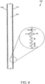
- FIG. 4 is a schematic front view of a portion of an example embodiment of spacer 106.
- Spacer 106 includes elongate strip 110, sidewall 124, and elongate strip 114.
- elongate strips 110 and 114 have an undulating shape.
- elongate strips 110 and 114 are formed of a metal ribbon, such as stainless steel, which is then bent into the undulating shape.
- Some possible embodiments of the undulating shape include sinusoidal, arcuate, square, rectangular, triangular, and other desired shapes.
- Some embodiments are formed of other materials, and can be formed by other processes, such as molding. Note that while FIG.
- elongate strip 114 may have an undulating shape that is much larger than the undulating shape of elongate strip 110 and vice versa.
- Another possible embodiment includes a flat elongate strip combined with either type of undulating strip. Other combinations and arrangements are also possible.
- the undulating shape resists permanent deformation, such as kinks and fractures. This allows elongate strips 110 and 114 to be more easily handled during manufacturing without damaging elongate strips 110 and 114.
- the undulating shape also increases the structural stability of elongate strips 110 and 114 to improve the ability of spacer 106 to withstand compressive and torsional loads.
- Some embodiments of elongate strips 110 and 114 are also able to extend and contract, which is beneficial, for example, when spacer 106 is formed around a corner. In some embodiments, the undulating shape reduces the need for notching or other stress relief.
- elongate strips 110 and 114 have material thicknesses T7.
- T7 is typically in a range from about 0.0001 inches to about 0.010 inches, and preferably from about 0.0003 inches to about 0.004 inches.
- Such thin material thickness reduces material costs and reduces thermal conductivity through elongate strips 110 and 114.
- the undulating shape of elongate strips 110 and 114 defines a waveform having a peak-to-peak amplitude and a peak-to-peak period.
- the peak-to-peak amplitude is also the overall thickness T9 of elongate strips 110 and 114.
- T9 is typically in a range from about 0.005 inches to about 0.1 inches, and preferably from about 0.02 inches to about 0.04 inches.
- P1 is the peak-to-peak period of undulating elongate strips 110 and 114.
- PI is typically in a range from about 0.005 inches to about 0.1 inches, and preferably from about 0.02 inches to about 0.04 inches. As described with reference to FIG. 7 , larger waveforms are used in other embodiments. Yet other embodiments include other dimensions.
- FIGS. 5-7 illustrate an example embodiment of spacer 106 in which continuous sidewalls 124 and 126 are arranged at edges of elongate strips 110 and 114.
- FIG. 5 is a schematic perspective view of the example spacer 106.
- FIG. 6 is a cross-sectional view of the example spacer 106 shown in FIG. 5 .
- FIG. 7 is a schematic side view of the example spacer 106 shown in FIG. 5 .
- Spacer 106 includes elongate strips 110 and 114 separated by sidewalls 124 and 126.
- sidewalls 124 and 126 are continuous along the length of spacer 106.
- Sidewalls 124 and 126 provide a uniform or substantially uniform spacing between elongate strips 110 and 114.
- spacer 106 are made according to the following process.
- Elongate strips 110 and 114 are typically formed first.
- the elongate strips 110 and 114 are made of a material, such as metal, that is formed into a thin and long ribbon (or multiple ribbons), such as by cutting the ribbon from a larger sheet.
- the thin and long ribbon is then shaped to include the undulating shape, if desired.
- the thin and long ribbon may also be punched or drilled to form apertures 116 in elongate strip 110, if desired. This is accomplished, for example, by passing the thin and long ribbon between a pair of corrugated rollers.
- the teeth of the roller bend the ribbon into an undulating shape. Different undulating shapes are possible in different embodiments by using rollers having appropriately shaped teeth.
- Example teeth shapes include sinusoidal teeth, triangular teeth, semi-circular teeth, square (or rectangular) teeth, saw-tooth shaped teeth, or other desired shapes.
- Elongate strips having no undulating pattern are used in some embodiments, in which case the thin and long ribbons typically do not require further shaping.
- the elongate strips 110 and 114 may alternatively be formed by other processes, such as by molding or extruding.
- elongate strips 110 and 114 are cut to a desired length while they are still in the long and thin ribbon form and prior to forming the undulating shape. In other embodiments, elongate strips are cut after forming the undulating shape.
- Another possible embodiment forms long and substantially continuous spacers 106 that are cut to length after forming spacer 106 including elongate strips 110 and 114 as well as sidewalls 124 and 126.
- spacer 106 is formed to have a length sufficient to extend along an entire perimeter of a window. In other embodiments, spacer 106 is formed to have a length sufficient for a single side or portion of a window.
- sidewalls 124 and 126 are formed between elongate strips 110 and 114.
- elongate strips 110 and 114 are passed through a guide that orients elongate strips 110 and 114 in a parallel arrangement and spaces them a desired distance apart.
- An extrusion die is arranged near the guide and between elongate strips 110 and 114.
- a sidewall material is extruded into the space between elongate strips 110 and 114, such as shown in FIG. 5 .
- Extrusion typically involves heating the sidewall material and using a hydraulic press to push the sidewall material through the extrusion die.
- continuous sidewalls 124 and 126 are formed at each end of elongate strips 110 and 114.
- the guide presses the extruded sidewalls 124 and 126 against interior surfaces of elongate strips 110 and 114, such that the sidewalls 124 and 126 conform to the undulating shape and adhere to elongate strips 110 and 114.
- sidewalls 124 and 126 are extruded into the space between elongate strips 110 and 114, while the elongate strips are held stationary in a guide or template that acts to maintain the appropriate alignment and spacing of the elongate strips 110 and 114 while sidewalls 124 and 126 are inserted therein.
- a robotic arm is used to guide an extrusion die along the space between elongate strips 110 and 114. The robotic arm moves the extrusion die to position the extruded sidewalls 124 and 126 within the elongate strips 110 and 114 that remain stationary during the process.
- extruded sidewalls 124 and 126 are formed in separate steps. In other embodiments, extruded sidewalls 124 and 126 are formed simultaneously, such as using two extrusion dies.
- sidewalls 124 and 126 are formed by passing the sidewall material through a series of rollers, to roll form the sidewalls into a desired shape. The roll formed sidewalls are then inserted between elongate strips 110 and 114. In some embodiments the sidewall material is heated and pressed against elongate strips 110 and 114 to shape and bond the sidewalls 124 and 126 to the elongate strips 110 and 114. In other embodiments, an adhesive is used to bond sidewalls 124 and 126 to elongate strips 110 and 114.
- sidewalls 124 and 126 are formed by molding. After molding, the sidewalls 124 and 126 are inserted into the space between elongate strips. In some embodiments a fastener, such as an adhesive, is used to bond sidewalls 124 and 126 to elongate strips 110 and 114. In another possible embodiment, portions of sidewalls 124 and 126 are melted and pressed against elongate strips 110 and 114 such that they grip the undulating shaped surface.
- a fastener such as an adhesive
- sidewalls 124 and 126 are rigid. When rigid sidewalls are mated with elongate strips 110 and 114, the resulting spacer also becomes rigid because the sidewalls 124 and 126 act to prevent flexing of elongate strips 110 and 114.
- sidewalls Although two sidewalls are illustrated in this example, other embodiments include one or more sidewalls (e.g., three, four, five, etc.). Further, sidewalls need not be located at sides of spacer 106. For example, one or more additional sidewalls are included at or about the center of spacer 106 in some embodiments.
- Additional features are formed in spacers 106 in some embodiments.
- An example of an additional feature is a muntin bar hole for mounting of a muntin bar.
- Muntin bar holes can be formed in spacer 106 or in elongate strip 116 either during the formation of elongate strip 116 or spacer 106, or after the formation of spacer 106.
- spacer 106 is connected to one or more sheets 102 and/or 104, such as shown in FIG. 1 .
- Spacer 106 can be connected to sheet 102 during or after the spacer 106 manufacturing processes discussed above.
- One or more sealant and/or adhesive materials are used in some embodiments to fasten spacer 106 to one or more sheets 102 and/or 104.
- FIG. 6 is a cross sectional view of the example spacer 106 shown in FIG. 5 .
- Spacer 106 includes elongate strip 110, elongate strip 114 sidewall 124 and sidewall 126.
- Elongate strip 110 includes external surface 340 and internal surface 342.
- Elongate strip 114 includes external surface 330 and internal surface 332.
- sidewalls 124 and 126 are flush with or substantially flush with edges of elongate strips 110 and 114.
- W1 is the overall width of spacer 106.
- W1 is typically in a range from about 0.1 inches to about 2 inches, and preferably from about 0.3 inches to about 1 inch.
- T1 is the overall thickness of spacer 106 from external surface 330 to external surface 340.
- T1 is typically in a range from about 0.02 inches to about 1 inch, and preferably from about 0.1 inches to about 0.5 inches.
- T2 is the distance between elongate strip 110 and elongate strip 114, and more specifically the distance from internal surface 332 to interior surface 342.
- T2 is also the height of sidewalls 124 and 126, which maintain the space between elongate strips 110 and 114.
- T2 is in a range from about 0.02 inches to about 0.5 inches, and preferably from about 0.05 inches to about 0.15 inches.
- elongate strips 110 and 114 and filler 112 are non-linear, such as having an undulating shape described below.
- T2 is an average thickness.
- G is the thickness of sidewalls 110 and 114. G is typically in a range from about 0.01 inches to about 0.5 inches, and preferably from about 0.1 inches to about 0.3 inches. Other embodiments include other dimensions than those discussed in this example.
- FIG. 7 is a schematic side view of the example spacer 106 shown in FIG. 5 .
- the spacer 106 includes elongate strips 110 and 114 and sidewall 124.
- This side view illustrates the undulating shape of example elongate strips 110 and 114. Further details regarding the undulating shape are described herein with reference to FIG. 4 .
- edges of sidewall 124 have an undulating shape that mates with the undulating shape of elongate strips 110 and 114.
- FIGS. 8-10 illustrate an example embodiment of spacer 106 in which continuous sidewalls 124 and 126 are arranged at intermediate positions between edges of elongate strips 110 and 114.
- FIG. 8 is a schematic perspective view of the example spacer of the example spacer 106.
- FIG. 9 is a cross-sectional view of the example spacer 106 shown in FIG. 8 .
- FIG. 10 is as schematic side view of the example spacer 106 shown in FIG. 8 .
- Spacer 106 includes elongate strips 110 and 114 separated by sidewalls 124 and 126.
- sidewalls 124 and 126 are continuous along the length of space or 106.
- the sidewalls 124 and 126 provide a uniform or substantially uniform spacing between elongate strips 110 and 114.
- offset distance S is typically in a range from about 0.01 inches to about 0.5 inches, and preferably from about 0.1 inches to about 0.3 inches. Other example dimensions shown in FIG. 9 are described in more detail herein, such as with reference to FIGS. 3 and 6 .
- the offset of sidewalls 124 and 126 provides additional structural stability to toward the center of elongate strips 110 and 114, such as to increase the resistance of space or 106 two pending or buckling under a load.
- the offset also provides a space for adhesive, sealants, or other materials.
- a space is defined between edges of elongate strips 110 and 114 and adjacent to offset sidewall 124.
- a bead of sealant is applied to this space in some embodiments.
- the sheet of transparent material is then applied to the bead to connect and seal edges of spacer 106 to the sheet of transparent material. Sealant is also applied to a space formed adjacent to offset sidewall 126 in some embodiments, which is then used to connect and seal the edge of spacer 106 to another sheet of transparent material.
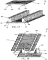
- FIGS. 11-15 illustrate another example embodiment of spacer 106 including divided sidewalls.
- FIG. 11 is a schematic perspective view of the example spacer 106 arranged in an assembled configuration.
- FIG. 12 is a schematic perspective view of the example spacer 106 shown in FIG. 11 arranged in an unassembled configuration.
- FIG. 13 is another schematic perspective view of the example spacer 106 shown in FIG. 11 arranged in an unassembled configuration.
- FIG. 14 is a cross-sectional view of the example spacer 106 shown in FIG. 11 arranged in an assembled configuration.
- FIG. 15 is a side view of the example spacer 106 shown in FIG. 11 arranged in an assembled configuration.
- Spacer 106 includes elongate strips 110 and 114 and sidewalls 124 and 126.
- elongate strip 110 includes apertures to allow moisture to pass through elongate strip 110.
- Filler 112 such as including a desiccant, is included within spacer 106 in some embodiments, but is not shown here. Some embodiments do not include filler 112.
- sidewalls 124 and 126 are located at an intermediate position between the edges of elongate strips 110 and 114, but in other embodiments sidewalls 124 and 126 are flush with edges of elongate strips 110 and 114.
- Spacer 106 includes sidewalls 124 and 126.
- the example spacer 106 shown in FIGS. 11-13 includes non-continuous sidewalls 124 and 126, including a plurality of spaced sidewall portions. Other embodiments, however, include continuous sidewalls without spaces.
- the space between sidewall portions allows spacer 106 to utilize the flexibility of elongate strips 110 and 114 and provides room for the spacer 106 to bend. As a result, spacer 106 can be bent to form a corner (such as a 90 degree corner).
- Sidewall 124 includes a first portion 801, second portion 803, and an example fastening mechanism.
- a particular example of a fastening mechanism includes a spline and a notched portion.
- First portion 801 includes a spline 802 as part of the fastening mechanism, alternatively referred to as a protrusion, and is connected to elongate strip 114.
- Second portion 803 includes a notched portion 804 as another portion of the fastening mechanism, and is connected to elongate strip 110.
- First and second portions 801 and 803 are engageable with each other using the fastening mechanism to form sidewall 124.
- first and second portions 801 and 803 are also separable from each other to separate elongate strip 110 from elongate strip 114.
- Sidewall 126 includes a first portion 805 and a second portion 807.
- First portion 805 includes a spline 806, alternatively referred to as a protrusion, and is connected to elongate strip 114.
- Second portion 807 includes a notched portion 808, and is connected to elongate strip 110.
- First and second portions 805 and 807 are engageable with each other to form sidewall 126.
- first and second portions 805 and 807 are also separable from each other to separate elongate strip 110 from elongate strip 114.
- first portions 801 and 805 are secured to elongate strip 114 and second portions 803 and 807 are secured to elongate strip 110.
- first and second portions 801, 805, 803, and 807 are formed using an extrusion process, which forms the first and second portions 801, 805, 803, and 807 onto the respective elongate strips 114 and 110.
- the first portions 801 and 805 are extruded individually in some embodiments, but are extruded simultaneously in other embodiments.
- the second portions 803 and 807 are extruded individually in some embodiments, but are extruded simultaneously in other embodiments.
- some embodiments pre-form first and second portions 801, 805, 803, and 807 and are later adhered or fastened to elongate strips 114 and 110.
- a portion of the pre-made first and second portions is melted in some embodiments and then pressed onto the respective elongate strip 114 or 110.
- elongate strips 110 and 114 can be secured together.
- a fabricator may press elongate strips 110 and 114 together.
- a machine may be used to press elongate strips 110 and 114 together.
- spacer 106 when spline 804 is disconnected from sidewalls 124 and 126, spacer 106 is flexible. Then, once spline 804 is connected to sidewalls 124 and 126, spacer 106 locks in place and becomes substantially rigid. In this way the spacer 106 is easily manipulated into a desired configuration and once there, is connected to lock the spacer 106 in the desired configuration.
- W1 is the overall width of spacer 106 and the distance between sheets 102 and 104. W1 is typically in a range from about 0.1 inches to about 2 inches, and preferably from about 0.3 inches to about 1 inch.
- T1 is the overall thickness of spacer 106 from external surface 330 to external surface 340. T1 is typically in a range from about 0.02 inches to about 1 inch, and preferably from about 0.1 inches to about 0.5 inches.
- T2 is the distance between elongate strip 110 and elongate strip 114, and more specifically the distance from internal surface 332 to interior surface 342. In other words, T2 is the height of sidewalls 124 and 126.
- T2 is in a range from about 0.02 inches to about 0.5 inches, and preferably from about 0.05 inches to about 0.15 inches. In some embodiments elongate strips 110 and 114 are not linear, such as having an undulating shape described below. Therefore, in some of these embodiments, T2 is an average thickness. G is the thickness of sidewalls 124 and 126. G is typically in a range from about 0.01 inches to about 0.5 inches, and preferably from about 0.1 inches to about 0.3 inches. Other embodiments include other dimensions.
- sidewalls 124 and 126 are offset from the edges of elongate strips 110 and 114.
- the offset distance S is typically in a range from about 0.01 inches to about 0.5 inches, and preferably from about 0.1 inches to about 0.3 inches.
- spacer 106 include sidewalls 124 and 126 that are divided into first and second portions. As shown in FIG. 14 , first portions 801 and 805 have a height M and second portions 803 and 807 have a height N. Height N does not include the height of spline 804, such as shown in FIG. 13 . The sum of M and N is equal to height T1.
- FIG. 15 shows a side view of the spacer 106 shown in FIG. 11 including a non-continuous sidewall 124, including a plurality of spaced sidewall portions 1502 and 1504. Additional sidewall portions are not visible in FIG. 15 .
- Y is the spacing between adjacent sidewall portions-such as sidewall portion 1502 and sidewall portion 1504. The space Y is typically in a range from about 0.001 inches to about 0.5 inches and preferably from about 0.01 inches to about 0.05 inches.
- J is the width of sidewall portions 1502 and 1504. The width J is typically in a range from about 0.01 inch to about 1 inch, and preferably from about 0.05 inches to about 0.3 inches.
- FIG. 16 is a schematic cross-sectional view of another possible embodiment of window assembly 100.
- Window assembly 100 includes sheet 102, sheet 104, and an example spacer 106.
- Spacer 106 includes elongate strip 110, elongate strip 114, sidewalls 124 and 126, first sealant 302 and 304, and second sealant 402 and 404.
- spacer 106 further includes fastener aperture 1002, fastener 1004, and intermediate member 1006.
- spacer 106 includes filler 112.
- intermediary member 1006 is a sheet of glass or plastic, that are included to form a triple-paned window.
- intermediary member is a film or plate.
- intermediary member 1006 is a film or plate of material that absorbs at least some of the sun's ultraviolet radiation as it passes through the window 100, thereby warming interior space 120.
- intermediary member 1006 reflects ultraviolet radiation, thereby cooling interior space 120 and preventing some or all of the ultraviolet radiation from passing through the window.
- intermediary member 1006 divides interior space into two or more regions.
- Intermediary member 1006 is a Mylar film in some embodiments.
- intermediary member 1006 is a muntin bar.
- Intermediary member 1006 acts, in some embodiments, to provide additional support to spacer 106.
- a benefit of some embodiments is that the addition of intermediary member 1006 does not require additional spacers 106 or sealants.
- connection of intermediary member 1006 to spacer 106 can be accomplished in various ways.
- One way is to punch or cut apertures 1002 in elongate strip 110 of spacer 106 at the desired location(s).
- apertures 1002 are arranged as slots and the like.
- a fastener 1002 is then inserted into the aperture and connected to elongate strip 110.
- a fastener is a screw.
- Another example is a pin.
- Apertures 1002 are not required in all embodiments.
- fastener 1004 is an adhesive that does not require apertures 1002.
- Other embodiments include a fastener 1004 and an adhesive.
- Some fasteners 1004 are also arranged to connect with an intermediary member 1006, to connect the intermediary member 1006 to spacer 106.
- An example of fastener 1004 is a muntin bar clip.
- FIGS. 17-20 illustrate another example embodiment of spacer 106.
- FIG. 17 is a perspective view of the example spacer 106 arranged in an unassembled configuration.
- FIG. 18 is another perspective view of the example spacer 106 shown in FIG. 17 arranged in an unassembled configuration.
- FIG. 19 is a cross-sectional view of the example spacer 106 shown in FIG. 17 arranged in an unassembled configuration.
- FIG. 20 is a side view of the example spacer 106 shown in FIG. 17 arranged in an unassembled configuration.
- Spacer 106 includes elongate strips 110 and 114 and sidewalls 124 and 126.
- elongate strip 110 includes apertures 116, such as to allow moisture to pass through elongate strip 110.
- spacer 106 includes non-continuous sidewalls sidewalls 124 and 126, including a plurality of sidewall portions. Sidewalls 124 and 126 provide a uniform or substantially uniform spacing between elongate strips 110 and 114.
- each portion of sidewalls 124 and 126 includes a fastening mechanism including a pair of hooks 1702 and 1704.
- Hooks 1702 and 1704 are configured such that hook 1702 is engagable with hook 1704.
- first portions 801 and 805 are separable from second portions 803 and 807.
- Hooks 1702 and 1704 are configured to be engageable by arranging first and second portions 801 and 803 and first and second portions 805 and 807 as shown in FIG. 17 , and then pressing them together (such as by applying a force to elongate strips 110 and 114) to cause hooks 1702 and 1704 to latch together.
- the latching of hooks 1702 and 1704 is performed using a zipper mechanism.
- a zipper mechanism can also be used to disengage hooks 1702 and 1704 in some embodiments.
- FIG. 19 is a cross-sectional view of the spacer 106 shown in FIG. 17 .
- sidewalls 124 and 126 are offset from the edges of elongate sheets 110 and 114, having an offset distance S. In other embodiments, sidewalls 124 and 126 are flush with the edges of elongate strips 110 and 114.
- Q is the height of first portions 801 and 805.
- P is the height of second portions 803 and 807.
- FIG. 20 is a side view of example spacer 106 shown in FIG. 17 .
- Spacer 106 includes sidewall portion 2002 and sidewall portion 2004. Additional side wall portions are not visible in FIG. 20 .
- Y is the distance of a space between adjacent sidewall portions 2002 and 2004.
- J is the width of sidewall portions 2002 and 2004. Examples of Y and J are discussed herein. Note that while FIGS. 17-20 show sidewalls 124 and 126 as being segmented into a plurality of sidewall portions, some embodiments include continuous sidewalls. In other words, in some embodiments, Y is equal to zero.
- Elongate strips 110 and 114 can be fabricated from various materials including, but not limited to, metals, plastics, and ceramics. In addition, elongate strips 110 and 114 can be fabricated via various methods including, but not limited to, roll forming, extrusion, molding, stamping, or a combination of these.
- FIGS. 21-22 illustrate another example embodiment of spacer 106.
- FIG. 21 is a schematic perspective view of the example spacer 106.
- FIG. 22 is a schematic cross-sectional view of the example spacer shown in FIG. 21 .
- spacer 106 includes elongate strips 110, elongate strip 114, sidewall 124, and sidewall 126.
- Sidewalls 124 and 126 include first portions 801 and 803 and second portions 805 and 807.
- elongate strip 110, first potion 803, and second portion 805 form a continuous piece.
- Elongate strip 114, first portion 801, and second portion 807 also form a continuous piece.
- elongate strips 110 and 114 are formed separately from sidewalls 124 and 126.
- elongate strips 110 and 114 are first formed, such as by bending long and thin ribbons of material into an undulating shape. Sidewalls 110 and 114 are then formed by extruding the sidewalls onto the elongate strips 110 and 114.
- a fastener is used, such as adhesive, to connect sidewalls 124 and 126 to elongate strips 110 and 114.
- First portions 801 and 803 of sidewalls 124 and 126 include a recessed region 2102 at an end.
- Second portions 805 and 807 include a protrusion 2104.
- Protrusions 2104 are configured to mate with recessed regions 2102 to connect first portions 801 and 803 with second portions 805 and 807.
- sidewalls 124 and 126 are located along the edges of elongate strips 110 and 114 in some embodiments, and are offset by a distance S from the edges of elongate strips in other embodiments.
- spacer 106 shown in FIGS. 21 and 22 may have dimensions W1, T, T2, and G similar to those describe above with regard to FIG. 14 .
- Other embodiments include other dimensions.
- first portions 2102 of elongate strips 110 and 114 include recessed regions 2102 in the form of grooves.
- Second portions 2104 of elongate strips 110 and 114 include protrusions 2104 in the form of tongues 2106.
- Recessed regions 2102 are formed such that they snap together with protrusions 2104 to form an assembled spacer 106.
- recessed regions 2102 have a slightly smaller width than protrusions 2104 such that when protrusions 2104 are pressed into recesses 2102, friction holds the pieces together.
- protrusions 2206 and 2208 have prongs 2210 (shown in FIG. 22 ) that engage receiver 2212 to hold elongate strips 110 and 114 together.
- a zipper mechanism is used to connect first portion 2102 with second portion 2104. In some embodiments the zipper is also used to disconnect first portion 2102 from second portion 2104.
- Elongate strips 110 and 114 are fabricated from possible materials including, but not limited to, metals, plastics, and ceramics. In addition, elongate strips 110 and 114 are fabricated via various possible methods including, but not limited to, casting, and extrusion.
- FIG. 23 illustrates another example embodiment of spacer 106.
- FIG. 23 is a cross-sectional view of spacer 106 including elongate strip 110, elongate strip 114, sidewall 124, and sidewall 126.
- Sidewalls 124 and 126 include first portions 2302 and second portions 2304. sidewalls 124 and 126.
- First portions 2302 of sidewalls 124 and 126 include recessed portions 2306.
- Second portions 2304 of sidewalls 124 and 126 include protrusions 2308.
- recessed portions 2306 are in the form of grooves.
- Protrusions 2308 are in the form of tongues.
- Protrusions 2308 are configured to mate with recessed portions 2306. Some embodiments are configured to snap together. Once connected, spacer 106 remains connected due to friction or an additional fastener, such as adhesive or sealant.
- elongate strip 110 and second portions 2304 are formed of a continuous piece of material.
- elongate strip 114 and first portions 2302 are formed of a continuous piece of material.
- spacer 106 is formed of long and thin ribbons of material that are bent, such as by roll forming, into the configuration shown. Other embodiments are made by processes such as extrusion or casting.
- FIG. 24 illustrates another embodiment of an example spacer 106.
- FIG. 24 is a cross-sectional view of spacer 106 including elongate strip 110, elongate strip 114, sidewall 124, and sidewall 126.
- Sidewalls 124 and 126 include first portions 2402 and second portions 2404.
- First portions 2402 of sidewalls 124 and 126 include recessed portions 2406.
- Second portions 2404 of sidewalls 124 and 126 include protrusions 2408.
- recessed portions 2406 are in the form of grooves that extend longitudinally along an end of first portions 2402.
- Protrusions 2408 are in the form of tongues that extend longitudinally along second portions 2404.
- Protrusions 2408 are configured to mate with recessed portions 2406. Some embodiments are configured to snap together. Once connected, spacer 106 remains connected due to friction. In another embodiment an additional fastener, such as adhesive or sealant, is used to connect first and second portions of spacer 106.
- elongate strip 110 and first portions 2402 are formed of a continuous piece of material.
- elongate strip 114 and second portions 2302 are formed of a continuous piece of material.
- spacer 106 is formed of long and thin ribbons of material that are bent, such as by roll forming, into the configuration shown. Other embodiments are made by processes such as extrusion or casting.
- FIG. 25 is a cross-sectional view of another example spacer 106 including elongate strip 110, elongate strip 114, sidewall 124, and sidewall 126.
- sidewalls 124 and 126 include first portions 2502 and second portions 2504.
- First portion 2502 includes recessed region 2506.
- Second portion 2504 includes recessed region 2508.
- recessed region 2508 is in the form of a groove.
- protrusion 2506 is in the form of a tongue.
- Other embodiments include a plurality of grooves and a plurality of tongues.
- Other possible embodiments include a plurality of teeth and a plurality of spaced recesses configured to receive the teeth therein.
- Elongate strips 110 and 114 may be made from materials including, but not limited to, metals and plastics. In addition, elongate strips 110 and 114 may be manufactured via methods including, but not limited to, rolling, bending, and extrusion. First portions 2502 including protrusions 2506 are formed directly into elongate strip 114 in some embodiments. Second portions 2504 are made by, for example, extruding a material onto elongate strip 110. Recessed region 2508 is formed in some embodiments through the extrusion process. In other embodiments, recessed region 2508 is formed by cutting, drilling, routing, or grinding a groove into a face at an end of second portion 2504.
- Second portion 2504 is made of a material such as metal, plastic, ceramics, or combinations of these materials.
- first portion 2504 is bonded to elongate sheet 110 by one or more fastening methods, such as thermal bonding, ultrasonic welding, adhesive, or use of another fastener.
- FIG. 26 is a cross-sectional view of another example spacer 106 including elongate strip 110, elongate strip 114, sidewall 124, and sidewall 126.
- elongate strip 114 includes recessed regions 2602 in the form of parallel grooves.
- Sidewalls 124 and 126 include protrusions 2604 extending out from the ends of the sidewalls 124 and 126.
- protrusions 2604 are in the form of tongues. The protrusions 2604 are configured to engage with recessed regions 2602.
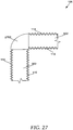
- FIG. 27 is a front view of an example spacer 106 and an example corner key 2702. Some embodiments of spacer 106 are not flexible. In such embodiments, the spacer 106 may be connected to a corner fastener, such as a corner key 2702.
- Spacer 106 includes elongate strip 110, sidewall 502, and elongate strip 114.
- elongate strips 110 and 114 have an undulating shape.
- a corner key 2702 is used to form the corner.
- Some embodiments of spacer 106 can be arranged to form a corner without corner key 2702.
- sidewall 502 is made from a material that is able to bend and flex without kinking or breaking.
- Elongate strips 110 and 114 include an undulating shape. As a result, elongate strips 110 and 114 are arranged to expand and compress as necessary.
- continuous sidewalls 124 and 126 may be constructed of a flexible material that allows spacer 106 to be bent.
- the material used to fabricate continuous sidewalls 124 and 126 may be heated to soften the material thereby making in pliable.
- the curves maybe formed while the material is in a pliable form.
- the material may then be allowed to set and/or cure such that a ridge or semi flexible corner is formed.
- the curves may be formed by cutting continuous strips of spacer 106 to form the corners. For instance, a continuous strip of spacer 106 may be cut along 45° angles to form a mitered corners.
- portions of plurality of sidewalls 124 and 126 may be removed to form a corner.
- portions of sidewall 124 (124a, 124b, and 124b) and sidewall 126 may be removed from elongate strip 114. With portions 124a, 124b, and 124c removed elongate strip 114 can be bent to form a corner. Once elongate strip 114 is bent elongate strip 110 may be secured via spline 804.
- spline 804 may have protuberances that contact notch 802 such that spline 804 does not move within notch 802 thereby forming a ridged corner. In other embodiments, spline 804 may be allowed to move within notch 802 such that spacer 106 may be bent to form a corner or other non-liner shape.
- window assemblies and window spacers some embodiments are used for other purposes.
- another possible embodiment according to the present disclosure is a spacer for a sealed unit.
Landscapes
- Structural Engineering (AREA)
- Engineering & Computer Science (AREA)
- Civil Engineering (AREA)
- Architecture (AREA)
- Securing Of Glass Panes Or The Like (AREA)
- Joining Of Glass To Other Materials (AREA)
- Laminated Bodies (AREA)
- Building Environments (AREA)
- Sealing Material Composition (AREA)
- Drying Of Gases (AREA)
- Gasket Seals (AREA)
- Extrusion Moulding Of Plastics Or The Like (AREA)
- Cell Separators (AREA)
- Connection Of Plates (AREA)
Abstract
Description
- This application is being filed on 13 November 2008, as a PCT International Patent application in the name of Infinite Edge Technologies, LLC, a U.S. national corporation, applicant for the designation of all countries except the U.S., and Paul Trpkovski, a citizen of the U.S., applicant for the designation of the U.S. only, and claims priority to
U.S. Provisional Patent Application Serial No. 60/987,681 filed on 13 November 2007 U.S. Provisional Patent Application Serial No. 61/038,803 filed on 24 March 2008 U.S. Provisional Patent Application Serial No. 61/049,593 filed on 01 May 2008 U.S. Provisional Patent Application Serial No. 61/049,599 filed on 01 May 2008 - Windows often include two facing sheets of glass separated by an air space. The air space reduces heat transfer through the window to insulate the interior of a building to which it is attached from external temperature variations. As a result, the energy efficiency of the building is improved, and a more even temperature distribution is achieved within the building.
- In general terms, this disclosure is directed to a window assembly and a window spacer. In one possible configuration and by non-limiting example, the window assembly includes a first sheet, a second sheet, and a spacer arranged between the first sheet and the second sheet. The spacer includes a first elongate strip, a second elongate strip, and continuous sidewalls or a plurality of sidewalls.
- One aspect is a spacer comprising: a first elongate strip; a second elongate strip; and at least one extruded sidewall engaging the first elongate strip to the second elongate strip.
- Another aspect is a sealed unit assembly comprising: a first transparent material; a second transparent material; and a spacer assembly disposed between the first and second transparent materials, the spacer assembly comprising: a first elongate strip having a first side adjacent the first transparent material and a second side adjacent the second transparent material; a second elongate strip having a first side adjacent the first transparent material and second side adjacent the second transparent material; and at least one sidewall connecting the first elongate strip to the second elongate strip.
- Yet another aspect is a method of making a spacer, the method comprising: arranging at least a portion of a first elongate strip and a second elongate strip in a spaced relationship, the first elongate strip including a first surface and the second elongate strip including a second surface; extruding a material through an extrusion nozzle to form at least one sidewall; and moving the extrusion nozzle relative to the first and second elongate strips while extruding to apply the material to the first surface of the first elongate strip and to the second surface of the second elongate strip to connect the first and second elongate strips.
- A further aspect is a method of making a spacer, the method comprising: forming a first sidewall portion onto a first elongate strip, the first sidewall portion including a protrusion; and forming a second sidewall portion onto a second elongate strip, the second sidewall portion including a notched portion.
- Another aspect is a spacer comprising: a first elongate strip; a second elongate strip; a first sidewall portion having a first fastening mechanism, the first sidewall portion attached to the first elongate strip; and a second sidewall portion having a second fastening mechanism, the second sidewall portion attached to the second elongate strip, wherein the first fastening mechanism is arranged and configured to securely engage with the second fastening mechanism to connect the first sidewall portion to the second sidewall portion.
- There is no requirement that an arrangement include all features characterized herein to obtain some advantage according to the present disclosure.
-
-
FIG. 1 is a schematic front view of a window assembly according to the present disclosure. -
FIG. 2 is a schematic perspective view of a corner section of the window assembly shown inFIG. 1 . -
FIG. 3 is a schematic cross-sectional view of a portion of the window assembly shown inFIG. 1 including a first sealant. -
FIG. 4 is a schematic front view of a portion of another embodiment of the spacer; -
FIG. 5 is a perspective schematic of a spacer. -
FIG. 6 is a schematic cross-sectional view of a portion of the spacer shown inFIG. 5 . -
FIG. 7 is a side view of a portion of the spacer shown inFIG. 5 . -
FIG. 8 is a perspective schematic of a spacer. -
FIG. 9 is a schematic cross-sectional view of a portion of the spacer shown inFIG. 8 . -
FIG. 10 is a side view of a portion of the spacer shown inFIG. 8 . -
FIG. 11 is a perspective schematic of a spacer. -
FIG. 12 is an exploded assembly perspective schematic of the spacer shown inFIG. 11 . -
FIG. 13 is an exploded assembly perspective schematic of the spacer shown inFIG. 11 . -
FIG. 14 is a schematic cross-sectional view of a portion of the spacer shown inFIG. 11 . -
FIG. 15 is a side view of a portion of the spacer shown inFIG. 11 . -
FIG. 16 is a schematic cross-sectional view of another embodiment of a window assembly including an intermediary member. -
FIG. 17 is an exploded assembly perspective schematic of a spacer. -
FIG. 18 is an exploded assembly perspective schematic of a spacer. -
FIG. 19 is a schematic cross-sectional view of a portion of the spacer shown inFIGS. 17 and 18 . -
FIG. 20 is a side view of a portion of the spacer shown inFIGS. 17 and 18 . -
FIG. 21 is an exploded assembly perspective schematic of a spacer. -
FIG. 22 is a schematic cross-sectional view of a portion of the spacer shown inFIG. 21 . -
FIG. 23 is a schematic cross-sectional view of a spacer. -
FIG. 24 is a schematic cross-sectional view of a spacer. -
FIG. 25 is a schematic cross-sectional view of a spacer. -
FIG. 26 is a schematic cross-sectional view of a spacer. -
FIG. 27 is a schematic front view of a portion of the spacer shown inFIG. 4 arranged in a corner configuration. - Various embodiments will be described in detail with reference to the drawings, wherein like reference numerals represent like parts and assemblies throughout the several views. Reference to various embodiments does not limit the scope of the claims attached hereto. Additionally, any examples set forth in this specification are not intended to be limiting and merely set forth some of the many possible embodiments for the appended claims.
-
FIGS. 1 and2 illustrate awindow assembly 100 according to the present disclosure.FIG. 1 is a schematic front view ofwindow assembly 100.FIG. 2 is a schematic perspective view of a corner section ofwindow assembly 100. -
Window assembly 100 includessheet 102,sheet 104, andspacer 106.Sheets sheets -
Spacer 106 includeselongate strip 110,elongate strip 114, andsidewalls spacer 106 also includesfiller 112.Spacer 106 is disposed betweensheets sheets spacer 106 is arranged to form a closed loop near to the perimeter ofsheets Spacer 106 is able to withstand compressive forces applied tosheets 102 and/or 104 to maintain a desired space betweensheets interior space 120 is defined withinwindow assembly 100 byspacer 106 andsheets -
Elongate strips - On their own,
elongate strips spacer 106 to be bent to form non-liner shapes (e.g., curves). Bending and torsional flexibility also allows for ease of window manufacturing. Such flexibility includes either elastic or plastic deformation such thatelongate strips window assembly 100. Some embodiments ofspacer 106 include elongate strips that do not have substantial flexibility, but rather are substantially rigid. In some embodiments,elongate strips spacer 106 is substantially rigid. In some embodiments,elongate strips filler 112 from ultraviolet radiation. - Some embodiments include
filler 112 that is arranged betweenelongate strip 110 andelongate strip 114. In some embodiments,filler 112 is a deformable material. Being deformable may allowspacer 106 to be formed around corners ofwindow assembly 100. In some embodiments,filler 112 is a desiccant that acts to remove moisture frominterior space 120. Desiccants include molecular sieve and silica gel type desiccants. One example of a desiccant is a beaded desiccant, such as PHONOSORB ® molecular sieve beads manufactured by W. R. Grace & Co. of Columbia, MD. If desired, an adhesive is used to attach beaded desiccant betweenelongate strips - In other embodiments,
filler 112 is a material that provides support to elongatestrips filler 112,filler 112 fills space betweenelongate strips elongate strips spacer 106 does not rely solely on the strength and stability ofelongate strips sheets elongate strips filler 112 is a matrix desiccant material that not only acts to provide structural support betweenelongate strips interior space 120. - Examples of a filler material include adhesive, foam, putty, resin, silicon rubber, or other materials. Some filler materials are a desiccant or include a desiccant, such as a matrix material. Matrix material includes desiccant and other filler material. Examples of matrix desiccants include those manufactured by W.R. Grace & Co. and H.B. Fuller Corporation. In some embodiments a beaded desiccant is combined with another filler material.
- In some embodiments,
filler 112 is made of a material providing thermal insulation. The thermal insulation reduces heat transfer throughspacer 106 both betweensheets interior space 120 and an exterior side ofspacer 106. - In some embodiments,
elongate strip 110 includes a plurality of apertures 116 (shown inFIG. 2 ).Apertures 116 allow gas and moisture to pass throughelongate strip 110. As a result, moisture located withininterior space 120 is allowed to pass throughelongate strip 110 where it is removed by desiccant offiller 112. In another embodiment,apertures 116 are used for registration. In yet another embodiment, apertures provide reduced thermal transfer. In one example,apertures 116 have a diameter in a range from about 0.002 inches to about 0.050 inches.Apertures 116 are made by any suitable method, such as cutting, punching, drilling, laser forming, or the like. -
Spacer 106 can be connected tosheets spacer 106 is connected tosheets window assembly 100 to supportspacer 106 betweensheets spacer 106 is connected to the frame or sash by a fastener, such as adhesive. Also in possible embodiments,spacer 106 is fastened to the frame or sash prior to installation ofsheets - In some embodiments, ends of
spacer 106 can be connected together with a fastener to form a closed loop. As such,spacer 106 andsheets interior space 120 ofwindow assembly 100.Interior space 120 reduces heat transfer throughwindow assembly 100. - When the
window assembly 100 is fully assembled, a gas is sealed withininterior space 120. In some embodiments, the gas is air. Other embodiments include oxygen, carbon dioxide, nitrogen, or other gases. Yet other embodiments include an inert gas, such as helium, neon or a noble gas such as krypton, argon, and the like. Combinations of these or other gases are used in other embodiments. -
FIG. 3 is a schematic cross-sectional view of a portion ofwindow assembly 100. In this embodiment,window assembly 100 includessheet 102,sheet 104,spacer 106, and also includessealants -
Sheet 102 includesouter surface 310,inner surface 312, andperimeter 314.Sheet 104 includesouter surface 320,inner surface 322, andperimeter 324. In one example, W is the thickness ofsheets -
Spacer 106 is arranged betweeninner surface 312 andinner surface 322.Spacer 106 is typically arranged nearperimeters perimeters spacer 106. D1 is typically in a range from about 0 inches to about 2 inches, and preferably from about 0.1 inches to about 0.5 inches. However, in other embodiments spacer 106 is arranged in other locations betweensheets -
Spacer 106 maintains a space betweensheets spacer 106 and the distance betweensheets -
Spacer 106 includeselongate strip 110,elongate strip 114,sidewall 124, andsidewall 126.Elongate strip 110 includesexternal surface 330,internal surface 332,edge 334,edge 336, andapertures 116.Elongate strip 114 includesexternal surface 340,internal surface 342,edge 344, and edge 346. In some embodiments,external surface 330 ofelongate strip 110 is visible by a person when looking throughwindow assembly 100.External surface 330 ofelongate strip 110 provides a clean and finished appearance tospacer 106. A benefit of some embodiments ofspacer 106 is that roll forming is not required to bendelongate strips - In one example, T1 is the overall thickness of
spacer 106 fromexternal surface 330 toexternal surface 340. T1 is typically in a range from about 0.02 inches to about 1 inch, and preferably from about 0.1 inches to about 0.5 inches. T2 is the distance betweenelongate strip 110 andelongate strip 114, and more specifically the distance frominternal surface 332 tointerior surface 342. T2 is also the thickness offiller material 112. T2 is in a range from about 0.02 inches to about 0.5 inches, and preferably from about 0.05 inches to about 0.15 inches. In some embodiments elongatestrips filler 112 are not linear, some examples have an undulating shape such as described below and shown inFIG. 4 . As a result,spacer 106 does not always have a constant thickness in all embodiments. As a result, T2 is an average thickness in some embodiments. Other embodiments include other dimensions. - In this embodiment, a
first sealant spacer 106 tosheets sealant 302 is applied to an edge ofspacer 106, such as onedges filler 112 and then pressed againstinner surface 312 ofsheet 102.Sealant 304 is also applied to an edge ofspacer 106, such as onedges 336 and 346, and an edge offiller 112 and then pressed againstinner surface 322 ofsheet 104. In other embodiments, beads ofsealant sheets spacer 106 is then pressed into the beads. - In some embodiments,
sealants sealants spacer 106 tosheets sealant spacer 106 is an orientation normal toinner surfaces sheets First sealant spacer 106 andsheets interior space 120. Examples offirst sealant -
First sealant spacer 106, such that thefirst sealant contacts surfaces elongate strips first sealant spacer 106 can be beneficial. For example, the additional contact area increases adhesion strength. The increased thickness ofsealants sealants external surfaces spacer 106. - In some embodiments, portions of
elongate strip 114 are connected to elongatestrip 110 withoutfiller 112 between. For example, a portion ofelongate strip 114 may be connected to elongatestrip 110 with a fastener, such as a adhesive, weld, rivet, or other fastener. -
FIG. 4 is a schematic front view of a portion of an example embodiment ofspacer 106.Spacer 106 includeselongate strip 110,sidewall 124, andelongate strip 114. In this embodiment,elongate strips elongate strips FIG. 4 showselongate strips elongate strip 114 may have an undulating shape that is much larger than the undulating shape ofelongate strip 110 and vice versa. Another possible embodiment includes a flat elongate strip combined with either type of undulating strip. Other combinations and arrangements are also possible. - One of the benefits of the undulating shape is that the flexibility of
elongate strips elongate strips elongate strips elongate strips spacer 106 to withstand compressive and torsional loads. Some embodiments ofelongate strips spacer 106 is formed around a corner. In some embodiments, the undulating shape reduces the need for notching or other stress relief. - In one example,
elongate strips elongate strips elongate strips elongate strips elongate strips FIG. 7 , larger waveforms are used in other embodiments. Yet other embodiments include other dimensions. -
FIGS. 5-7 illustrate an example embodiment ofspacer 106 in whichcontinuous sidewalls elongate strips FIG. 5 is a schematic perspective view of theexample spacer 106.FIG. 6 is a cross-sectional view of theexample spacer 106 shown inFIG. 5 .FIG. 7 is a schematic side view of theexample spacer 106 shown inFIG. 5 .Spacer 106 includeselongate strips sidewalls spacer 106.Sidewalls elongate strips - Some embodiments of
spacer 106 are made according to the following process. Elongate strips 110 and 114 are typically formed first. The elongate strips 110 and 114 are made of a material, such as metal, that is formed into a thin and long ribbon (or multiple ribbons), such as by cutting the ribbon from a larger sheet. The thin and long ribbon is then shaped to include the undulating shape, if desired. The thin and long ribbon may also be punched or drilled to formapertures 116 inelongate strip 110, if desired. This is accomplished, for example, by passing the thin and long ribbon between a pair of corrugated rollers. The teeth of the roller bend the ribbon into an undulating shape. Different undulating shapes are possible in different embodiments by using rollers having appropriately shaped teeth. Example teeth shapes include sinusoidal teeth, triangular teeth, semi-circular teeth, square (or rectangular) teeth, saw-tooth shaped teeth, or other desired shapes. Elongate strips having no undulating pattern are used in some embodiments, in which case the thin and long ribbons typically do not require further shaping. The elongate strips 110 and 114 may alternatively be formed by other processes, such as by molding or extruding. - In some embodiments,
elongate strips continuous spacers 106 that are cut to length after formingspacer 106 includingelongate strips sidewalls spacer 106 is formed to have a length sufficient for a single side or portion of a window. - After the
elongate strips elongate strips elongate strips elongate strips elongate strips elongate strips elongate strips FIG. 5 . Extrusion typically involves heating the sidewall material and using a hydraulic press to push the sidewall material through the extrusion die. In this example,continuous sidewalls elongate strips sidewalls elongate strips sidewalls strips - In another possible embodiment, sidewalls 124 and 126 are extruded into the space between
elongate strips elongate strips sidewalls elongate strips sidewalls elongate strips - In another possible embodiment, sidewalls 124 and 126 are formed by passing the sidewall material through a series of rollers, to roll form the sidewalls into a desired shape. The roll formed sidewalls are then inserted between
elongate strips elongate strips sidewalls elongate strips sidewalls strips - In another possible embodiment, sidewalls 124 and 126 are formed by molding. After molding, the
sidewalls sidewalls strips sidewalls elongate strips - In some embodiments, sidewalls 124 and 126 are rigid. When rigid sidewalls are mated with
elongate strips sidewalls elongate strips sidewalls spacer 106 is flexible. - Although two sidewalls are illustrated in this example, other embodiments include one or more sidewalls (e.g., three, four, five, etc.). Further, sidewalls need not be located at sides of
spacer 106. For example, one or more additional sidewalls are included at or about the center ofspacer 106 in some embodiments. - Additional features are formed in
spacers 106 in some embodiments. An example of an additional feature is a muntin bar hole for mounting of a muntin bar. Muntin bar holes can be formed inspacer 106 or inelongate strip 116 either during the formation ofelongate strip 116 orspacer 106, or after the formation ofspacer 106. - In some embodiments spacer 106 is connected to one or
more sheets 102 and/or 104, such as shown inFIG. 1 .Spacer 106 can be connected tosheet 102 during or after thespacer 106 manufacturing processes discussed above. One or more sealant and/or adhesive materials are used in some embodiments to fastenspacer 106 to one ormore sheets 102 and/or 104. -
FIG. 6 is a cross sectional view of theexample spacer 106 shown inFIG. 5 .Spacer 106 includeselongate strip 110,elongate strip 114sidewall 124 andsidewall 126.Elongate strip 110 includesexternal surface 340 andinternal surface 342.Elongate strip 114 includesexternal surface 330 andinternal surface 332. In the example embodiment shown inFIG. 6 ,sidewalls elongate strips - Example dimensions are now described with reference to
FIG. 6 for an example embodiment as shown, but other embodiments include other dimensions. In one example, W1 is the overall width ofspacer 106. W1 is typically in a range from about 0.1 inches to about 2 inches, and preferably from about 0.3 inches to about 1 inch. T1 is the overall thickness ofspacer 106 fromexternal surface 330 toexternal surface 340. T1 is typically in a range from about 0.02 inches to about 1 inch, and preferably from about 0.1 inches to about 0.5 inches. T2 is the distance betweenelongate strip 110 andelongate strip 114, and more specifically the distance frominternal surface 332 tointerior surface 342. T2 is also the height ofsidewalls elongate strips strips filler 112 are non-linear, such as having an undulating shape described below. In some of these embodiments, T2 is an average thickness. G is the thickness ofsidewalls -
FIG. 7 is a schematic side view of theexample spacer 106 shown inFIG. 5 . Thespacer 106 includeselongate strips sidewall 124. This side view illustrates the undulating shape of exampleelongate strips FIG. 4 . In this example, edges ofsidewall 124 have an undulating shape that mates with the undulating shape ofelongate strips -
FIGS. 8-10 illustrate an example embodiment ofspacer 106 in whichcontinuous sidewalls elongate strips FIG. 8 is a schematic perspective view of the example spacer of theexample spacer 106.FIG. 9 is a cross-sectional view of theexample spacer 106 shown inFIG. 8 .FIG. 10 is as schematic side view of theexample spacer 106 shown inFIG. 8 .Spacer 106 includeselongate strips sidewalls sidewalls elongate strips - In the example embodiment of
spacer 106, shown inFIGS. 8-10 ,sidewalls strips FIG. 9 by offset distance S. In one example, offset distance S is typically in a range from about 0.01 inches to about 0.5 inches, and preferably from about 0.1 inches to about 0.3 inches. Other example dimensions shown inFIG. 9 are described in more detail herein, such as with reference toFIGS. 3 and6 . - In some embodiments, the offset of
sidewalls elongate strips elongate strips sidewall 124. A bead of sealant is applied to this space in some embodiments. The sheet of transparent material is then applied to the bead to connect and seal edges ofspacer 106 to the sheet of transparent material. Sealant is also applied to a space formed adjacent to offsetsidewall 126 in some embodiments, which is then used to connect and seal the edge ofspacer 106 to another sheet of transparent material. -
FIGS. 11-15 illustrate another example embodiment ofspacer 106 including divided sidewalls.FIG. 11 is a schematic perspective view of theexample spacer 106 arranged in an assembled configuration.FIG. 12 is a schematic perspective view of theexample spacer 106 shown inFIG. 11 arranged in an unassembled configuration.FIG. 13 is another schematic perspective view of theexample spacer 106 shown inFIG. 11 arranged in an unassembled configuration.FIG. 14 is a cross-sectional view of theexample spacer 106 shown inFIG. 11 arranged in an assembled configuration.FIG. 15 is a side view of theexample spacer 106 shown inFIG. 11 arranged in an assembled configuration. -
Spacer 106 includeselongate strips sidewalls strip 110 includes apertures to allow moisture to pass throughelongate strip 110.Filler 112, such as including a desiccant, is included withinspacer 106 in some embodiments, but is not shown here. Some embodiments do not includefiller 112. - In this example, sidewalls 124 and 126 are located at an intermediate position between the edges of
elongate strips elongate strips -
Spacer 106 includessidewalls example spacer 106 shown inFIGS. 11-13 includesnon-continuous sidewalls spacer 106 to utilize the flexibility ofelongate strips spacer 106 to bend. As a result,spacer 106 can be bent to form a corner (such as a 90 degree corner). -
Sidewall 124 includes afirst portion 801,second portion 803, and an example fastening mechanism. A particular example of a fastening mechanism includes a spline and a notched portion. However, it is recognized that a variety of other fastening mechanisms are used in other embodiments. Some alternate examples of fastening mechanisms are described herein.First portion 801 includes aspline 802 as part of the fastening mechanism, alternatively referred to as a protrusion, and is connected to elongatestrip 114.Second portion 803 includes a notchedportion 804 as another portion of the fastening mechanism, and is connected to elongatestrip 110. First andsecond portions sidewall 124. In some embodiments, first andsecond portions elongate strip 110 fromelongate strip 114. -
Sidewall 126 includes afirst portion 805 and asecond portion 807.First portion 805 includes aspline 806, alternatively referred to as a protrusion, and is connected to elongatestrip 114.Second portion 807 includes a notchedportion 808, and is connected to elongatestrip 110. First andsecond portions sidewall 126. In some embodiments, first andsecond portions elongate strip 110 fromelongate strip 114. - During fabrication,
first portions strip 114 andsecond portions strip 110. In some embodiments, first andsecond portions second portions elongate strips first portions second portions - Rather than extruding directly onto
elongate strips second portions strips elongate strip - Once
splines 804 are attached to elongatestrip 110 and thenotch 802 portion of plurality ofsidewalls elongate strips elongate strips elongate strips - In some embodiments, when
spline 804 is disconnected fromsidewalls spacer 106 is flexible. Then, oncespline 804 is connected to sidewalls 124 and 126,spacer 106 locks in place and becomes substantially rigid. In this way thespacer 106 is easily manipulated into a desired configuration and once there, is connected to lock thespacer 106 in the desired configuration. - Example dimensions of
spacer 106 are shown inFIG. 14 . In one example, W1 is the overall width ofspacer 106 and the distance betweensheets spacer 106 fromexternal surface 330 toexternal surface 340. T1 is typically in a range from about 0.02 inches to about 1 inch, and preferably from about 0.1 inches to about 0.5 inches. T2 is the distance betweenelongate strip 110 andelongate strip 114, and more specifically the distance frominternal surface 332 tointerior surface 342. In other words, T2 is the height ofsidewalls strips sidewalls - In
FIG. 14 ,sidewalls elongate strips sidewalls elongate strips - Some embodiments of
spacer 106 includesidewalls FIG. 14 ,first portions second portions spline 804, such as shown inFIG. 13 . The sum of M and N is equal to height T1. -
FIG. 15 shows a side view of thespacer 106 shown inFIG. 11 including anon-continuous sidewall 124, including a plurality of spacedsidewall portions FIG. 15 . Y is the spacing between adjacent sidewall portions-such assidewall portion 1502 andsidewall portion 1504. The space Y is typically in a range from about 0.001 inches to about 0.5 inches and preferably from about 0.01 inches to about 0.05 inches. J is the width ofsidewall portions -
FIG. 16 is a schematic cross-sectional view of another possible embodiment ofwindow assembly 100.Window assembly 100 includessheet 102,sheet 104, and anexample spacer 106.Spacer 106 includeselongate strip 110,elongate strip 114,sidewalls first sealant second sealant spacer 106 further includesfastener aperture 1002,fastener 1004, andintermediate member 1006. In some embodiments spacer 106 includesfiller 112. - Some embodiments include an
intermediary member 106 that is connected tospacer 106. In one embodiment,intermediary member 1006 is a sheet of glass or plastic, that are included to form a triple-paned window. In another embodiment, intermediary member is a film or plate. For example,intermediary member 1006 is a film or plate of material that absorbs at least some of the sun's ultraviolet radiation as it passes through thewindow 100, thereby warminginterior space 120. In another embodiment,intermediary member 1006 reflects ultraviolet radiation, thereby coolinginterior space 120 and preventing some or all of the ultraviolet radiation from passing through the window. In some embodiments,intermediary member 1006 divides interior space into two or more regions.Intermediary member 1006 is a Mylar film in some embodiments. In another embodiment,intermediary member 1006 is a muntin bar.Intermediary member 1006 acts, in some embodiments, to provide additional support to spacer 106. A benefit of some embodiments is that the addition ofintermediary member 1006 does not requireadditional spacers 106 or sealants. - Connection of
intermediary member 1006 to spacer 106 can be accomplished in various ways. One way is to punch or cutapertures 1002 inelongate strip 110 ofspacer 106 at the desired location(s). In some embodiments,apertures 1002 are arranged as slots and the like. Afastener 1002 is then inserted into the aperture and connected to elongatestrip 110. One example of a fastener is a screw. Another example is a pin.Apertures 1002 are not required in all embodiments. In some embodiments,fastener 1004 is an adhesive that does not requireapertures 1002. Other embodiments include afastener 1004 and an adhesive. Somefasteners 1004 are also arranged to connect with anintermediary member 1006, to connect theintermediary member 1006 tospacer 106. An example offastener 1004 is a muntin bar clip. -
FIGS. 17-20 illustrate another example embodiment ofspacer 106.FIG. 17 is a perspective view of theexample spacer 106 arranged in an unassembled configuration.FIG. 18 is another perspective view of theexample spacer 106 shown inFIG. 17 arranged in an unassembled configuration.FIG. 19 is a cross-sectional view of theexample spacer 106 shown inFIG. 17 arranged in an unassembled configuration.FIG. 20 is a side view of theexample spacer 106 shown inFIG. 17 arranged in an unassembled configuration. -
Spacer 106 includeselongate strips sidewalls elongate strip 110 includesapertures 116, such as to allow moisture to pass throughelongate strip 110. In this embodiment,spacer 106 includes non-continuous sidewalls sidewalls 124 and 126, including a plurality of sidewall portions.Sidewalls elongate strips - In this example, each portion of
sidewalls hooks Hooks hook 1702 is engagable withhook 1704. When disengaged,first portions second portions Hooks second portions second portions FIG. 17 , and then pressing them together (such as by applying a force to elongatestrips 110 and 114) to causehooks hooks hooks -
FIG. 19 is a cross-sectional view of thespacer 106 shown inFIG. 17 . InFIG. 19 sidewalls elongate sheets elongate strips first portions second portions -
FIG. 20 is a side view ofexample spacer 106 shown inFIG. 17 .Spacer 106 includessidewall portion 2002 andsidewall portion 2004. Additional side wall portions are not visible inFIG. 20 . Y is the distance of a space betweenadjacent sidewall portions sidewall portions FIGS. 17-20 show sidewalls - Elongate strips 110 and 114 can be fabricated from various materials including, but not limited to, metals, plastics, and ceramics. In addition,
elongate strips -
FIGS. 21-22 illustrate another example embodiment ofspacer 106.FIG. 21 is a schematic perspective view of theexample spacer 106.FIG. 22 is a schematic cross-sectional view of the example spacer shown inFIG. 21 . As discussed above,spacer 106 includeselongate strips 110,elongate strip 114,sidewall 124, andsidewall 126.Sidewalls first portions second portions - In this embodiment,
elongate strip 110,first potion 803, andsecond portion 805 form a continuous piece.Elongate strip 114,first portion 801, andsecond portion 807 also form a continuous piece. In other embodiments,elongate strips sidewalls elongate strips Sidewalls elongate strips sidewalls strips -
First portions sidewalls region 2102 at an end.Second portions protrusion 2104.Protrusions 2104 are configured to mate with recessedregions 2102 to connectfirst portions second portions - As described above,
sidewalls elongate strips spacer 106 shown inFIGS. 21 and 22 may have dimensions W1, T, T2, and G similar to those describe above with regard toFIG. 14 . Other embodiments include other dimensions. - In some embodiments, as shown in
FIGS. 21 and 22 ,first portions 2102 ofelongate strips regions 2102 in the form of grooves.Second portions 2104 ofelongate strips protrusions 2104 in the form of tongues 2106. Recessedregions 2102 are formed such that they snap together withprotrusions 2104 to form an assembledspacer 106. In some embodiments recessedregions 2102 have a slightly smaller width thanprotrusions 2104 such that whenprotrusions 2104 are pressed intorecesses 2102, friction holds the pieces together. In other embodiments, protrusions 2206 and 2208 have prongs 2210 (shown inFIG. 22 ) that engagereceiver 2212 to holdelongate strips - In some embodiments a zipper mechanism is used to connect
first portion 2102 withsecond portion 2104. In some embodiments the zipper is also used to disconnectfirst portion 2102 fromsecond portion 2104. - Elongate strips 110 and 114 are fabricated from possible materials including, but not limited to, metals, plastics, and ceramics. In addition,
elongate strips -
FIG. 23 illustrates another example embodiment ofspacer 106.FIG. 23 is a cross-sectional view ofspacer 106 includingelongate strip 110,elongate strip 114,sidewall 124, andsidewall 126.Sidewalls first portions 2302 andsecond portions 2304.sidewalls -
First portions 2302 ofsidewalls portions 2306.Second portions 2304 ofsidewalls protrusions 2308. In this example, recessedportions 2306 are in the form of grooves.Protrusions 2308 are in the form of tongues.Protrusions 2308 are configured to mate with recessedportions 2306. Some embodiments are configured to snap together. Once connected,spacer 106 remains connected due to friction or an additional fastener, such as adhesive or sealant. - In this embodiment,
elongate strip 110 andsecond portions 2304 are formed of a continuous piece of material. Similarly,elongate strip 114 andfirst portions 2302 are formed of a continuous piece of material. In some embodiments spacer 106 is formed of long and thin ribbons of material that are bent, such as by roll forming, into the configuration shown. Other embodiments are made by processes such as extrusion or casting. -
FIG. 24 illustrates another embodiment of anexample spacer 106.FIG. 24 is a cross-sectional view ofspacer 106 includingelongate strip 110,elongate strip 114,sidewall 124, andsidewall 126.Sidewalls first portions 2402 andsecond portions 2404. -
First portions 2402 ofsidewalls portions 2406.Second portions 2404 ofsidewalls protrusions 2408. In this example, recessedportions 2406 are in the form of grooves that extend longitudinally along an end offirst portions 2402.Protrusions 2408 are in the form of tongues that extend longitudinally alongsecond portions 2404.Protrusions 2408 are configured to mate with recessedportions 2406. Some embodiments are configured to snap together. Once connected,spacer 106 remains connected due to friction. In another embodiment an additional fastener, such as adhesive or sealant, is used to connect first and second portions ofspacer 106. - In this embodiment,
elongate strip 110 andfirst portions 2402 are formed of a continuous piece of material. Similarly,elongate strip 114 andsecond portions 2302 are formed of a continuous piece of material. In some embodiments spacer 106 is formed of long and thin ribbons of material that are bent, such as by roll forming, into the configuration shown. Other embodiments are made by processes such as extrusion or casting. -
FIG. 25 is a cross-sectional view of anotherexample spacer 106 includingelongate strip 110,elongate strip 114,sidewall 124, andsidewall 126. In this embodiment, sidewalls 124 and 126 includefirst portions 2502 andsecond portions 2504.First portion 2502 includes recessedregion 2506.Second portion 2504 includes recessedregion 2508. In some embodiments recessedregion 2508 is in the form of a groove. In some embodiments protrusion 2506 is in the form of a tongue. Other embodiments include a plurality of grooves and a plurality of tongues. Other possible embodiments include a plurality of teeth and a plurality of spaced recesses configured to receive the teeth therein. - Elongate strips 110 and 114 may be made from materials including, but not limited to, metals and plastics. In addition,
elongate strips First portions 2502 includingprotrusions 2506 are formed directly intoelongate strip 114 in some embodiments.Second portions 2504 are made by, for example, extruding a material ontoelongate strip 110. Recessedregion 2508 is formed in some embodiments through the extrusion process. In other embodiments, recessedregion 2508 is formed by cutting, drilling, routing, or grinding a groove into a face at an end ofsecond portion 2504.Second portion 2504 is made of a material such as metal, plastic, ceramics, or combinations of these materials. In some embodimentsfirst portion 2504 is bonded to elongatesheet 110 by one or more fastening methods, such as thermal bonding, ultrasonic welding, adhesive, or use of another fastener. -
FIG. 26 is a cross-sectional view of anotherexample spacer 106 includingelongate strip 110,elongate strip 114,sidewall 124, andsidewall 126. In this embodiment,elongate strip 114 includes recessedregions 2602 in the form of parallel grooves.Sidewalls protrusions 2604 extending out from the ends of thesidewalls protrusions 2604 are configured to engage with recessedregions 2602. -
FIG. 27 is a front view of anexample spacer 106 and anexample corner key 2702. Some embodiments ofspacer 106 are not flexible. In such embodiments, thespacer 106 may be connected to a corner fastener, such as acorner key 2702. -
Spacer 106 includeselongate strip 110,sidewall 502, andelongate strip 114. In this embodiment,elongate strips corner key 2702 is used to form the corner. Some embodiments ofspacer 106 can be arranged to form a corner withoutcorner key 2702. In these embodiments,sidewall 502 is made from a material that is able to bend and flex without kinking or breaking. - Elongate strips 110 and 114 include an undulating shape. As a result,
elongate strips continuous sidewalls continuous sidewalls spacer 106 to be bent. In other embodiments employingcontinuous sidewalls continuous sidewalls continuous sidewalls continuous sidewalls spacer 106 to form the corners. For instance, a continuous strip ofspacer 106 may be cut along 45° angles to form a mitered corners. - In embodiments employing plurality of
sidewalls sidewalls FIG. 11 , portions of sidewall 124 (124a, 124b, and 124b) and sidewall 126 (removed portions not shown) may be removed fromelongate strip 114. Withportions elongate strip 114 can be bent to form a corner. Onceelongate strip 114 is bentelongate strip 110 may be secured viaspline 804. In an embodiment,spline 804 may have protuberances that contactnotch 802 such thatspline 804 does not move withinnotch 802 thereby forming a ridged corner. In other embodiments,spline 804 may be allowed to move withinnotch 802 such thatspacer 106 may be bent to form a corner or other non-liner shape. - Although the present disclosure refers to window assemblies and window spacers, some embodiments are used for other purposes. For example, another possible embodiment according to the present disclosure is a spacer for a sealed unit.
- The various embodiments described above are provided by way of illustration only and should not be construed to limit the claims attached hereto. Those skilled in the art will readily recognize various modifications and changes that may be made without following the example embodiments and applications illustrated and described herein, and without departing from the intended scope of the following claims.
Claims (15)
- A method of making a spacer for a window assembly including at least two window sheets of a transparent, translucent, or semi-transparent material, the method comprising:arranging at least a portion of first and second elongate strips of a metal material in a spaced relationship, the first elongate strip defining a first surface and the second elongate strip defining a second surface;extruding a non-metal material through an extrusion die to form first and second sidewalls; andmoving the first and second elongate strips relative to the extrusion die while extruding to apply the first and second sidewalls to the first surface of the first elongate strip and to the second surface of the second elongate strip to connect the first and second elongate strips,wherein the first and second elongate strips are arranged and configured to extend between the at least two window sheets.
- The method of claim 1, wherein arranging and moving the first and second elongate strips comprises passing the first and second elongate strips through a guide that orients the first and second elongate strips in a parallel arrangement and in the spaced relationship.
- The method of claim 2, wherein the guide and the extrusion die are arranged such that the first and second sidewalls are offset by an offset distance from outer edges of the first and second elongate strips, the offset distance being greater than zero.
- The method of claim 2, wherein the guide causes the first and second sidewalls to be pressed against the first and second surfaces of the first and second elongate strips, respectively.
- The method of claim 4, wherein extruding the non-metal material comprises heating the non-metal material and using a device to force the non-metal material through the extrusion die.
- The method of claim 4, wherein at least one of the first and second elongate strips defines an undulating shape.
- The method of claim 6, further comprising passing at least one of the first and second elongate strips through a set of corrugated rollers to form the undulating shape.
- The method of claim 6, wherein the first and second elongate strips each define the undulating shape.
- The method of claim 6, wherein the first elongate strip defines the undulating shape and the second elongate strip defines a different undulating shape.
- The method of claim 1, wherein the metal material is stainless steel.
- The method of claim 1, wherein the non-metal material is plastic.
- The method of claim 1, further comprising depositing a filler material in an interior space defined between the first and second elongate strips and the first and second sidewalls.
- The method of claim 12, further comprising depositing a sealant material in outer spaces defined between (i) the first and second elongate strips and the first sidewall and (ii) the first and second elongate strips and the second sidewall, wherein the outer spaces are distinct from the interior space.
- The method of claim 12, wherein the filler material comprises a desiccant.
- The method of claim 14, wherein one of the first and second elongate strips defines a plurality of apertures.
Applications Claiming Priority (6)
| Application Number | Priority Date | Filing Date | Title |
|---|---|---|---|
| US98768107P | 2007-11-13 | 2007-11-13 | |
| US3880308P | 2008-03-24 | 2008-03-24 | |
| US4959908P | 2008-05-01 | 2008-05-01 | |
| US4959308P | 2008-05-01 | 2008-05-01 | |
| PCT/US2008/083445 WO2009064919A1 (en) | 2007-11-13 | 2008-11-13 | Box spacer with sidewalls |
| EP08849504.9A EP2220322B1 (en) | 2007-11-13 | 2008-11-13 | Box spacer with sidewalls |
Related Parent Applications (2)
| Application Number | Title | Priority Date | Filing Date |
|---|---|---|---|
| PCT/US2008/083445 Previously-Filed-Application WO2009064919A1 (en) | 2007-11-13 | 2008-11-13 | Box spacer with sidewalls |
| EP08849504.9A Division EP2220322B1 (en) | 2007-11-13 | 2008-11-13 | Box spacer with sidewalls |
Publications (2)
| Publication Number | Publication Date |
|---|---|
| EP3318713A1 true EP3318713A1 (en) | 2018-05-09 |
| EP3318713B1 EP3318713B1 (en) | 2022-09-21 |
Family
ID=40219375
Family Applications (6)
| Application Number | Title | Priority Date | Filing Date |
|---|---|---|---|
| EP08849306A Withdrawn EP2220321A1 (en) | 2007-11-13 | 2008-11-13 | Reinforced window spacer |
| EP08849504.9A Active EP2220322B1 (en) | 2007-11-13 | 2008-11-13 | Box spacer with sidewalls |
| EP08850093A Withdrawn EP2220323A1 (en) | 2007-11-13 | 2008-11-13 | Material with undulating shape |
| EP08849236.8A Active EP2220320B1 (en) | 2007-11-13 | 2008-11-13 | Sealed unit and spacer |
| EP08850693A Withdrawn EP2220324A1 (en) | 2007-11-13 | 2008-11-13 | Sealed unit and spacer with stabilized elongate strip |
| EP17195481.1A Active EP3318713B1 (en) | 2007-11-13 | 2008-11-13 | Box spacer with sidewalls |
Family Applications Before (5)
| Application Number | Title | Priority Date | Filing Date |
|---|---|---|---|
| EP08849306A Withdrawn EP2220321A1 (en) | 2007-11-13 | 2008-11-13 | Reinforced window spacer |
| EP08849504.9A Active EP2220322B1 (en) | 2007-11-13 | 2008-11-13 | Box spacer with sidewalls |
| EP08850093A Withdrawn EP2220323A1 (en) | 2007-11-13 | 2008-11-13 | Material with undulating shape |
| EP08849236.8A Active EP2220320B1 (en) | 2007-11-13 | 2008-11-13 | Sealed unit and spacer |
| EP08850693A Withdrawn EP2220324A1 (en) | 2007-11-13 | 2008-11-13 | Sealed unit and spacer with stabilized elongate strip |
Country Status (15)
| Country | Link |
|---|---|
| US (9) | US8596024B2 (en) |
| EP (6) | EP2220321A1 (en) |
| JP (2) | JP2011503403A (en) |
| KR (2) | KR20100097154A (en) |
| CN (3) | CN101918667A (en) |
| AU (2) | AU2008320959A1 (en) |
| BR (2) | BRPI0820152B1 (en) |
| CA (3) | CA2704970C (en) |
| DK (3) | DK2220320T3 (en) |
| ES (1) | ES2751099T3 (en) |
| MX (2) | MX2010005259A (en) |
| PL (3) | PL3318713T3 (en) |
| RU (2) | RU2476659C2 (en) |
| TW (5) | TW200934952A (en) |
| WO (5) | WO2009064919A1 (en) |
Families Citing this family (70)
| Publication number | Priority date | Publication date | Assignee | Title |
|---|---|---|---|---|
| US20070227097A1 (en) * | 2006-03-15 | 2007-10-04 | Gallagher Raymond G | Composite spacer bar for reducing heat transfer from a warm side to a cold side along an edge of an insulated glazing unit |
| US20100031591A1 (en) * | 2007-03-15 | 2010-02-11 | Gallagher Raymond G | Composite spacer bar for reducing heat transfer from a warm side to a cold side along an edge of an insulated glazing unit |
| WO2009064919A1 (en) | 2007-11-13 | 2009-05-22 | Infinite Edge Technologies, Llc | Box spacer with sidewalls |
| US8967219B2 (en) | 2010-06-10 | 2015-03-03 | Guardian Ig, Llc | Window spacer applicator |
| US9309714B2 (en) | 2007-11-13 | 2016-04-12 | Guardian Ig, Llc | Rotating spacer applicator for window assembly |
| EP2454437B1 (en) * | 2009-07-14 | 2017-05-10 | Guardian IG, LLC | Stretched strips for spacer and sealed unit |
| US8731699B2 (en) * | 2009-09-29 | 2014-05-20 | Hp3 Software, Inc. | Dynamic, lean insulated glass unit assembly line scheduler |
| GB2487685B (en) * | 2009-09-29 | 2015-04-01 | P E T Polymer Extrusion Technology Inc | Apparatus for making insulating translucent panel assemblies |
| DE102010006127A1 (en) * | 2010-01-29 | 2011-08-04 | Technoform Glass Insulation Holding GmbH, 34277 | Spacer profile with reinforcement layer |
| US9689195B2 (en) * | 2010-03-27 | 2017-06-27 | Robert S. Jones | Vacuum insulating glass unit with viscous edge seal |
| US9732552B2 (en) | 2010-03-27 | 2017-08-15 | Robert S. Jones | Vacuum insulating glass unit with viscous edge seal |
| CA2793476C (en) * | 2010-03-27 | 2018-05-01 | Robert S. Jones | Vacuum insulating glass unit with viscous edge seal |
| DE102010049806A1 (en) * | 2010-10-27 | 2012-05-03 | Technoform Glass Insulation Holding Gmbh | Spacer profile and insulating disk unit with such a spacer profile |
| US9228389B2 (en) | 2010-12-17 | 2016-01-05 | Guardian Ig, Llc | Triple pane window spacer, window assembly and methods for manufacturing same |
| DE102010056128A1 (en) * | 2010-12-22 | 2012-06-28 | Glaswerke Arnold Gmbh & Co. Kg | Spacer for insulating glass units and method for its production |
| WO2012092466A1 (en) | 2010-12-29 | 2012-07-05 | Guardian Industries Corp. | Grid keeper for insulating glass unit, and insulating glass unit incorporating the same |
| DE102011009359A1 (en) | 2011-01-25 | 2012-07-26 | Technoform Glass Insulation Holding Gmbh | Spacer profile and insulating disk unit with such a spacer profile |
| US8776350B2 (en) | 2011-05-31 | 2014-07-15 | Guardian Industries Corp. | Spacer systems for insulated glass (IG) units, and/or methods of making the same |
| US8871316B2 (en) | 2011-05-31 | 2014-10-28 | Guardian Industries Corp. | Insulated glass (IG) units including spacer systems, and/or methods of making the same |
| US9556066B2 (en) | 2011-12-13 | 2017-01-31 | Guardian Industries Corp. | Insulating glass units with low-E and antireflective coatings, and/or methods of making the same |
| DE202012013491U1 (en) * | 2012-01-13 | 2017-02-24 | Saint-Gobain Glass France | Spacers for insulating glazings |
| EP2626496A1 (en) | 2012-02-10 | 2013-08-14 | Technoform Glass Insulation Holding GmbH | Spacer profile for a spacer frame for an insulating glass unit with interspace elements and insulating glass unit |
| EP2855819A4 (en) | 2012-05-29 | 2016-01-06 | Quanex Ig Systems Inc | Spacer for insulating glazing unit |
| US20130319598A1 (en) | 2012-05-30 | 2013-12-05 | Cardinal Ig Company | Asymmetrical insulating glass unit and spacer system |
| US9260907B2 (en) | 2012-10-22 | 2016-02-16 | Guardian Ig, Llc | Triple pane window spacer having a sunken intermediate pane |
| US9689196B2 (en) | 2012-10-22 | 2017-06-27 | Guardian Ig, Llc | Assembly equipment line and method for windows |
| USD736594S1 (en) | 2012-12-13 | 2015-08-18 | Cardinal Ig Company | Spacer for a multi-pane glazing unit |
| US8789343B2 (en) | 2012-12-13 | 2014-07-29 | Cardinal Ig Company | Glazing unit spacer technology |
| US9234381B2 (en) | 2013-01-07 | 2016-01-12 | WexEnergy LLC | Supplemental window for fenestration |
| US9845636B2 (en) | 2013-01-07 | 2017-12-19 | WexEnergy LLC | Frameless supplemental window for fenestration |
| US10196850B2 (en) | 2013-01-07 | 2019-02-05 | WexEnergy LLC | Frameless supplemental window for fenestration |
| US10883303B2 (en) | 2013-01-07 | 2021-01-05 | WexEnergy LLC | Frameless supplemental window for fenestration |
| US9691163B2 (en) | 2013-01-07 | 2017-06-27 | Wexenergy Innovations Llc | System and method of measuring distances related to an object utilizing ancillary objects |
| US9663983B2 (en) | 2013-01-07 | 2017-05-30 | WexEnergy LLC | Frameless supplemental window for fenestration incorporating infiltration blockers |
| JP6419168B2 (en) * | 2013-09-30 | 2018-11-07 | サン−ゴバン グラス フランスSaint−Gobain Glass France | Multi-layer glass spacer |
| EP3080376A1 (en) | 2013-12-12 | 2016-10-19 | Saint-Gobain Glass France | Spacer for insulating glazing units, comprising extruded profiled seal |
| WO2015086457A2 (en) | 2013-12-12 | 2015-06-18 | Saint-Gobain Glass France | Double glazing having improved sealing |
| US10301868B2 (en) | 2014-06-27 | 2019-05-28 | Saint-Gobain Glass France | Insulated glazing comprising a spacer, and production method |
| TR201815606T4 (en) | 2014-06-27 | 2018-11-21 | Saint Gobain | Insulating glazing with spacer and the method for making it, as well as its use as building glazing. |
| EP3421709B2 (en) | 2014-09-25 | 2022-11-30 | Saint-Gobain Glass France | Spacer for insulating glazing |
| JP2016081775A (en) * | 2014-10-17 | 2016-05-16 | パナソニックIpマネジメント株式会社 | Lighting device and attachment structure of the same |
| MX2017011083A (en) | 2015-03-02 | 2017-11-10 | Saint Gobain | Glass fiber-reinforced spacer for insulating glazing. |
| US9759007B2 (en) | 2015-05-18 | 2017-09-12 | PDS IG Holding, LLC | Spacer for retaining muntin bars and method of assembly |
| USD777345S1 (en) | 2015-05-21 | 2017-01-24 | Saint-Gobain Glass France | Spacer bar |
| KR20180045006A (en) * | 2015-09-03 | 2018-05-03 | 쌩-고벵 글래스 프랑스 | Method and apparatus for filling a spacer frame for manufacturing insulating glazing |
| US9556666B1 (en) | 2015-09-03 | 2017-01-31 | Cardinal Ig Company | Automatic adjustable nozzle systems |
| AU2016316631A1 (en) * | 2015-09-04 | 2018-03-29 | Agc Glass Europe | Highly insulated floor-to-ceiling window |
| EP3418053B1 (en) * | 2016-02-19 | 2020-04-22 | Riken Technos Corporation | Decorative sheet |
| RU2620241C1 (en) | 2016-03-30 | 2017-05-23 | Общество с ограниченной ответственностью "Теплориум" | Energy efficient light-transparent construction |
| US20180001501A1 (en) * | 2016-06-03 | 2018-01-04 | Unique Fabricating, Inc. | Multiple-axis articulating member and method for making same |
| USD837411S1 (en) * | 2016-12-09 | 2019-01-01 | Panasonic Intellectual Property Management Co., Ltd. | Vacuum-insulated glass plate |
| USD837412S1 (en) * | 2017-01-20 | 2019-01-01 | Panasonic Intellectual Property Management Co., Ltd. | Vacuum-insulated glass plate |
| CN107035279A (en) * | 2017-04-17 | 2017-08-11 | 姚献忠 | Sets of transparent panels component |
| US10227817B2 (en) * | 2017-05-08 | 2019-03-12 | Advanced Building Systems, Inc. | Vented insulated glass unit |
| IL271006B2 (en) | 2017-05-30 | 2024-09-01 | WexEnergy LLC | Complementary window without a frame for window design |
| US10107027B1 (en) | 2017-10-24 | 2018-10-23 | Quaker Window Products Co. | Thermally enhanced multi-component window |
| US10947772B2 (en) | 2017-10-24 | 2021-03-16 | Quaker Window Products Co. | Thermally enhanced multi-component glass doors and windows |
| JP2020070135A (en) * | 2018-10-30 | 2020-05-07 | 株式会社日立製作所 | Elevator scale structure |
| US11352831B2 (en) | 2019-05-24 | 2022-06-07 | PDS IG Holding LLC | Glass seal tracking spacer applicator |
| DE102019121691A1 (en) * | 2019-08-12 | 2021-02-18 | Ensinger Gmbh | Spacer for insulating glass panes |
| DE102019121690A1 (en) * | 2019-08-12 | 2021-02-18 | Ensinger Gmbh | Spacer for insulating glass panes |
| EP4130420A4 (en) * | 2020-04-01 | 2024-04-03 | Aestech Ltd | TRANSLUCENT ENCLOSURE STRUCTURE |
| US11859439B2 (en) | 2020-04-15 | 2024-01-02 | Vitro Flat Glass Llc | Low thermal conducting spacer assembly for an insulating glazing unit |
| KR20230040307A (en) | 2020-07-15 | 2023-03-22 | 가디언 글라스, 엘엘씨 | Dynamic Shades with Reactive Gas Compatible Desiccants and/or Related Methods |
| WO2022072813A1 (en) * | 2020-10-02 | 2022-04-07 | WexEnergy LLC | Frameless supplemental window for fenestration |
| WO2022144775A1 (en) | 2020-12-30 | 2022-07-07 | Guardian Glass, LLC | Millimeter radio-wave signal compatibile electrostatically-driven shade, and/or method of making the same |
| US12428903B2 (en) * | 2021-01-27 | 2025-09-30 | Saint-Gobain Glass France | Spacer for insulating glazing |
| US12116832B2 (en) | 2021-02-17 | 2024-10-15 | Vitro Flat Glass Llc | Multi-pane insulated glass unit having a relaxed film forming a third pane and method of making the same |
| CN115059388B (en) * | 2022-07-11 | 2024-01-19 | 常熟中信建材有限公司 | High-stability hollow mosaic glass with built-in sunshade shutter and assembling process thereof |
| WO2025117232A1 (en) * | 2023-11-27 | 2025-06-05 | Corning Incorporated | Igu having suspended thin center pane and related methods and systems |
Citations (2)
| Publication number | Priority date | Publication date | Assignee | Title |
|---|---|---|---|---|
| DE4101277A1 (en) * | 1991-01-17 | 1992-07-23 | Grimm Friedrich Bjoern | Double glazing - has profiled distance pieces to hold the panes at gap with elastic adhesive to transfer forces from one pane side to the other |
| US5890289A (en) * | 1991-12-26 | 1999-04-06 | Bay Mills Limited | Method of making an insulating spacer for spacing apart panes of a multiple pane unit |
Family Cites Families (294)
| Publication number | Priority date | Publication date | Assignee | Title |
|---|---|---|---|---|
| US423704A (en) * | 1890-03-18 | Grinding-mill | ||
| US1310206A (en) | 1919-07-15 | Rolling mill | ||
| US367236A (en) * | 1887-07-26 | Relief-valve for compressors | ||
| US32436A (en) * | 1861-05-28 | Adjustable weatheb-strip | ||
| US1425207A (en) | 1919-04-29 | 1922-08-08 | Bert B Milner | Corrugated metal plate |
| US1988964A (en) * | 1932-07-15 | 1935-01-22 | Barrows Charles Storrs | Pane |
| US2125690A (en) * | 1933-11-02 | 1938-08-02 | Budd Edward G Mfg Co | Box section beam |
| US2213468A (en) * | 1935-12-26 | 1940-09-03 | Libbey Owens Ford Glass Co | Multiple glass sheet glazing unit |
| US2122453A (en) * | 1936-05-26 | 1938-07-05 | Pittsburgh Plate Glass Co | Double glazing unit |
| US2235680A (en) * | 1937-07-14 | 1941-03-18 | Libbey Owens Ford Glass Co | Multiple glass sheet glazing unit and method of making the same |
| US2275812A (en) * | 1938-05-13 | 1942-03-10 | Robert Mitchell Co Ltd | Preformed multipane glazing unit |
| US2356386A (en) * | 1941-05-19 | 1944-08-22 | Couelle Jacques | Structural member |
| US2597097A (en) * | 1943-01-11 | 1952-05-20 | Libbey Owens Ford Glass Co | Multiple glazing unit |
| US2419400A (en) * | 1943-01-11 | 1947-04-22 | Libbey Owens Ford Glass Co | Multiple glazing unit |
| US2507097A (en) * | 1945-10-15 | 1950-05-09 | Abbott Lab | Ampoule opener |
| US2618819A (en) | 1947-05-02 | 1952-11-25 | Libbey Owens Ford Glass Co | Edging strip |
| US2708774A (en) * | 1949-11-29 | 1955-05-24 | Rca Corp | Multiple glazed unit |
| US2838810A (en) * | 1954-07-09 | 1958-06-17 | Pittsburgh Plate Glass Co | Multiple glazed unit |
| US2833031A (en) * | 1954-11-09 | 1958-05-06 | Columbus Auto Parts | Method of making curved corrugated wedge members |
| US2885746A (en) * | 1956-06-13 | 1959-05-12 | B B Chem Co | Articles for removing moisture from enclosed spaces and structures including the articles |
| US3045297A (en) * | 1956-07-31 | 1962-07-24 | Ljungdahl Erland Samuel | Multiple pane window unit |
| US3027608A (en) * | 1959-06-22 | 1962-04-03 | Libbey Owens Ford Glass Co | Multiple glass sheet glazing units |
| DE1175192B (en) | 1959-11-26 | 1964-08-06 | Joachim Pfeiffer Dipl Ing | Method and device for ironing strangfoermigem good, z. B. Band |
| DE1259823B (en) | 1962-03-02 | 1968-02-01 | Steinmueller Gmbh L & C | Method and device for the production of sheet metal strips with a corrugated central zone |
| DE1189518B (en) | 1962-12-24 | 1965-03-25 | Leipziger Buchbindereimaschine | Device for turning over and deforming thread-like staple legs |
| US3280523A (en) | 1964-01-08 | 1966-10-25 | Pittsburgh Plate Glass Co | Multiple glazing unit |
| DE1904907U (en) | 1964-01-15 | 1964-11-19 | Walter Dipl Ing Ruf | SHOT-PROOF ALL-ROAD WHEEL. |
| US3288667A (en) | 1964-04-29 | 1966-11-29 | Pittsburgh Plate Glass Co | Sealing element |
| US3614848A (en) * | 1964-06-09 | 1971-10-26 | Pullman Inc | Foam structural element |
| US3367161A (en) * | 1965-08-18 | 1968-02-06 | Hrant J. Avakian | Louvered zigzag fin strip forming machine |
| US3538668A (en) * | 1967-12-01 | 1970-11-10 | Howard A Anderson | Reinforced architectural shapes |
| DE1752713C2 (en) | 1968-07-05 | 1983-09-01 | Mannesmann AG, 4000 Düsseldorf | Process for rolling tubes in a stretch-reducing mill |
| DE1904907A1 (en) * | 1969-01-31 | 1970-08-13 | Bostik Gmbh | Sealed multiple washer with spacer |
| DE6903785U (en) | 1969-01-31 | 1969-10-30 | Bostik Gmbh | SEALED MULTIPLE PANEL WITH SPACER |
| DE2035481A1 (en) * | 1970-07-17 | 1972-01-20 | Fa Friedrich Kocks, 4000 Dusseldorf | Process for rolling fine iron |
| LU62150A1 (en) | 1970-11-27 | 1972-08-03 | ||
| US3957406A (en) * | 1971-04-26 | 1976-05-18 | Usm Corporation | Hot melt applicators |
| US3661099A (en) * | 1971-04-28 | 1972-05-09 | Westvaco Corp | Pallet deck |
| DE2123655B2 (en) * | 1971-05-13 | 1973-10-18 | Ungerer Geb. Dollinger, Irma, 7530 Pforzheim | Combined stretching line for metal strips |
| SE362279B (en) | 1971-08-09 | 1973-12-03 | Emmaboda Glasverk Ab | |
| US3839137A (en) | 1972-01-28 | 1974-10-01 | Du Pont | Corrugated film having increased stiffness |
| DE2304223C3 (en) * | 1972-01-31 | 1979-02-01 | Johan Caspar Dipl.-Ing. Hoevik Falkenberg (Norwegen) | Cross-corrugated sheet metal web for nailable components |
| US3758996A (en) | 1972-05-05 | 1973-09-18 | Ppg Industries Inc | Multiple glazed unit |
| US3974011A (en) | 1972-11-23 | 1976-08-10 | Friedrich G. K. Jarchow | Method for cementing in the manufacture of double-pane insulating glass units |
| US4027517A (en) * | 1974-01-07 | 1977-06-07 | Bodnar Ernest R | Method and apparatus for embossing sheet metal strip and sheet metal panel |
| SE390185B (en) | 1974-03-01 | 1976-12-06 | Berthagen N T L | ISOLERRUTA |
| US3971243A (en) | 1974-04-18 | 1976-07-27 | The Boeing Company | Method for die forming strip material |
| GB1508778A (en) | 1974-06-26 | 1978-04-26 | Glaverbel | Hollow panel units |
| US3935893A (en) * | 1974-07-15 | 1976-02-03 | General Motors Corporation | Self-sealing vehicle tire and sealant composition |
| FR2287278A1 (en) * | 1974-10-10 | 1976-05-07 | Saint Gobain | PROCESS AND DEVICE FOR COATING THE SLICES OF A MULTIPLE GLAZING |
| DE2456991A1 (en) | 1974-12-03 | 1976-06-16 | Jenaer Glaswerk Schott & Gen | COMPONENT WITH AGAINST FIRE RESISTANT GLAZING |
| FR2294314A1 (en) * | 1974-12-11 | 1976-07-09 | Saint Gobain | SPACER FOR MULTIPLE GLAZING |
| US4113799A (en) | 1975-07-14 | 1978-09-12 | Rocket Research Corp. | Elastomeric sealant composition |
| US3956998A (en) | 1975-08-06 | 1976-05-18 | Bavetz James W | Furnace wall assembly having reduced thermal conductivity |
| GB1531134A (en) | 1975-08-20 | 1978-11-01 | Atomic Energy Authority Uk | Methods of fabricating bodies and to bodies so fabricated |
| US4080482A (en) | 1975-11-11 | 1978-03-21 | D. C. Glass Limited | Spacer for glass sealed unit and interlock member therefor |
| US4002048A (en) * | 1975-12-19 | 1977-01-11 | Aetna-Standard Engineering Company | Method of stretch reducing of tubular stock |
| US4074480A (en) * | 1976-02-12 | 1978-02-21 | Burton Henry W G | Kit for converting single-glazed window to double-glazed window |
| US4057945A (en) | 1976-10-19 | 1977-11-15 | Gerald Kessler | Insulating spacer for double insulated glass |
| US4113905A (en) * | 1977-01-06 | 1978-09-12 | Gerald Kessler | D.i.g. foam spacer |
| US4057944A (en) | 1977-03-11 | 1977-11-15 | Videre Corporation | Thermally insulated panel |
| JPS5828150Y2 (en) | 1977-03-26 | 1983-06-18 | 吉田工業株式会社 | Heat and sound insulation glass equipment |
| US4084029A (en) * | 1977-07-25 | 1978-04-11 | The Boeing Company | Sine wave beam web and method of manufacture |
| GB1579726A (en) | 1977-08-23 | 1980-11-26 | Pilkington Brothers Ltd | Multiple glazing |
| CH630993A5 (en) | 1977-11-04 | 1982-07-15 | Giesbrecht Ag | Insulating-glass pane |
| US4222209A (en) * | 1978-02-27 | 1980-09-16 | Peterson Metal Products, Ltd. | Cornerpiece for use in multiple pane window |
| US4233833A (en) | 1978-06-05 | 1980-11-18 | United States Gypsum Company | Method for stretching sheet metal and structural members formed therefrom |
| US4222213A (en) * | 1978-11-14 | 1980-09-16 | Gerald Kessler | Insulating spacer for double insulated glass |
| US4241146A (en) | 1978-11-20 | 1980-12-23 | Eugene W. Sivachenko | Corrugated plate having variable material thickness and method for making same |
| US4431691A (en) | 1979-01-29 | 1984-02-14 | Tremco, Incorporated | Dimensionally stable sealant and spacer strip and composite structures comprising the same |
| US4244203A (en) * | 1979-03-29 | 1981-01-13 | Olin Corporation | Cooperative rolling process and apparatus |
| JPS5938841B2 (en) * | 1980-01-14 | 1984-09-19 | 新日本製鐵株式会社 | Method of rolling a strip by winding it around a roll |
| DE3026129A1 (en) | 1980-07-10 | 1982-02-04 | Erwin Kampf Gmbh & Co Maschinenfabrik, 5276 Wiehl | METAL TAPE RACKING SYSTEM |
| DE3047338C2 (en) | 1980-12-16 | 1987-08-20 | Fr. Xaver Bayer Isolierglasfabrik Kg, 7807 Elzach | Spacer for multi-pane insulating glass |
| AT370346B (en) * | 1981-03-25 | 1983-03-25 | Voest Alpine Ag | PLANT FOR THE HOT ROLLING OF TAPE OR TABLED ROLLED GOODS |
| AT370706B (en) * | 1981-04-03 | 1983-04-25 | Lisec Peter | DEVICE FOR ASSEMBLING INSULATING GLASS PANELS |
| AT385499B (en) | 1981-05-11 | 1988-04-11 | Lisec Peter | DEVICE FOR PRESSING INSULATING GLASS |
| US4453855A (en) * | 1981-08-03 | 1984-06-12 | Thermetic Glass, Inc. | Corner construction for spacer used in multi-pane windows |
| US4520602A (en) * | 1981-08-03 | 1985-06-04 | Thermetic Glass, Inc. | Multi-pane sealed window and method for forming same |
| DE3143659A1 (en) | 1981-11-04 | 1983-05-11 | Helmut Lingemann GmbH & Co, 5600 Wuppertal | DRYER APPLICATION FOR INSULATING GLAZING OR THE LIKE, AND A SPACER PROFILE FILLED WITH THE DRYING APPLICATION |
| CH659506A5 (en) * | 1981-12-03 | 1987-01-30 | Peter Lisec | DEVICE FOR ADAPTING SPACER FRAME. |
| US4400338A (en) | 1982-02-16 | 1983-08-23 | Tremco, Incorporated | Method for making sealant |
| US4499703A (en) * | 1982-02-16 | 1985-02-19 | The Bf Goodrich Company | Method of retro-fitting windows |
| FR2525314A1 (en) | 1982-04-16 | 1983-10-21 | Phenol Eng | Airtight joint for vacuum container - has mercury bath in groove in flexible elastomer housing |
| AT383581B (en) * | 1982-04-19 | 1987-07-27 | Lisec Peter | DEVICE FOR FILLING SPACER FRAME WITH HYGROSCOPIC MATERIAL |
| US4481800A (en) | 1982-10-22 | 1984-11-13 | Kennecott Corporation | Cold rolling mill for metal strip |
| GB8319264D0 (en) | 1983-07-15 | 1983-08-17 | Omniglass Ltd | Corner for spacer strip of sealed window units |
| GB2138063B (en) * | 1983-02-04 | 1986-04-30 | Glaverbel | Multiple glazing unit |
| CA1246978A (en) | 1983-04-09 | 1988-12-20 | Franz Bayer | Method of and apparatus for making spacers for use in multiple-pane windows of the like |
| DE3337058C1 (en) | 1983-10-12 | 1985-02-28 | Julius & August Erbslöh GmbH & Co, 5600 Wuppertal | Spacers for windows, doors or the like. |
| GB8311813D0 (en) * | 1983-04-29 | 1983-06-02 | West G A W | Coding and storing raster scan images |
| DE3379761D1 (en) | 1983-06-16 | 1989-06-01 | Olin Corp | Multi-gauge metal strip, method of forming same and leadframes produced therefrom |
| AT379860B (en) | 1983-11-16 | 1986-03-10 | Steinleitner Wolfgang Ing | SPACER FOR INSULATING GLAZING |
| DE3404006A1 (en) | 1984-02-06 | 1985-08-08 | Karl 7531 Neuhausen Lenhardt | DEVICE FOR APPLYING AN ADHESIVE STRING OF PLASTIC TO A GLASS PANEL |
| AT405724B (en) * | 1984-06-14 | 1999-11-25 | Lisec Peter | DEVICE FOR MACHINING THE EDGE AREAS OF A GLASS PANEL |
| AT395710B (en) | 1984-07-05 | 1993-02-25 | Lisec Peter | DEVICE FOR SMOOTHING SEALING MEASURES ON INSULATING GLASS |
| GB2162228B (en) * | 1984-07-25 | 1987-07-15 | Sanden Corp | Double-glazed window for a refrigerator |
| SE453108B (en) * | 1984-08-10 | 1988-01-11 | Lars Eriksson | SPACES FOR THE CREATION OF A CLOSED SPACE BETWEEN TWO GLASS SHEETS |
| AT379359B (en) | 1984-08-22 | 1985-12-27 | Eckelt Josef | METHOD AND DEVICE FOR PRODUCING A SPACER FOR INSULATING WINDOWS |
| AT380528B (en) * | 1984-10-11 | 1986-06-10 | Eckelt Josef | METHOD AND DEVICE FOR PRODUCING A SPACER FOR INSULATING WINDOWS |
| US4567710A (en) * | 1985-02-19 | 1986-02-04 | Reed Michael R | Multiple glazed panel |
| US4951927A (en) * | 1985-03-11 | 1990-08-28 | Libbey-Owens-Ford Co. | Method of making an encapsulated multiple glazed unit |
| DE3545418A1 (en) | 1985-10-17 | 1987-04-23 | Gartner & Co J | SPACERS |
| DE3539153C1 (en) | 1985-11-05 | 1986-07-17 | Sundwiger Eisenhütte Maschinenfabrik Grah & Co, 5870 Hemer | System for straightening and slitting metal strips |
| CA1290625C (en) * | 1985-11-07 | 1991-10-15 | Gunter Berdan | Spacer assembly for multiple glazed unit |
| DE3539878A1 (en) * | 1985-11-11 | 1987-05-14 | Karl Lenhardt | SPACERS ON A DEVICE FOR CONNECTING TWO GLASS PANELS TO AN EDGE-INSERTED INSULATING GLASS DISC |
| DE3637561A1 (en) * | 1985-11-18 | 1987-05-21 | Lisec Peter | Device for fitting flexible spacers on glass panels |
| US4881355A (en) | 1986-03-12 | 1989-11-21 | Usg Interiors, Inc. | Cold roll-formed structures and method and apparatus for producing same |
| US4654057A (en) | 1986-04-01 | 1987-03-31 | Rhodes Barry V | Dehumidifier |
| DE3762534D1 (en) * | 1986-06-05 | 1990-06-07 | Peter Lisec | DEVICE FOR ADAPTING SPACER FRAME. |
| AT390433B (en) | 1986-09-01 | 1990-05-10 | Lisec Peter | DEVICE FOR APPLYING FLEXIBLE SPACERS |
| CA1285177C (en) | 1986-09-22 | 1991-06-25 | Michael Glover | Multiple pane sealed glazing unit |
| DE3633620A1 (en) | 1986-10-02 | 1988-04-14 | Gartner & Co J | THERMAL INSULATING WINDOW OR FACADE ARRANGEMENT IN THE TRANSPARENT AREA |
| US4835130A (en) | 1986-10-16 | 1989-05-30 | Tremco Incorporated | Selectively permeable zeolite adsorbents and sealants made therefrom |
| JPH07115586B2 (en) * | 1986-10-27 | 1995-12-13 | 一仁 深澤 | Car body shock absorber |
| CA1290624C (en) | 1986-10-31 | 1991-10-15 | Kenneth R. Parker | Insulating glass unit |
| AT390946B (en) | 1986-11-03 | 1990-07-25 | Lisec Peter | DEVICE FOR SHAPING A CORNER AND CRESSING THE ENDS OF FLEXIBLE SPACERS |
| US4814215A (en) | 1986-11-07 | 1989-03-21 | The B. F. Goodrich Company | Adhesive composition, process, and product |
| US4808452A (en) * | 1986-11-14 | 1989-02-28 | Products Research & Chemical Corp. | Multi-pane thermally insulating construction |
| US4780164A (en) | 1986-11-20 | 1988-10-25 | Cardinal Ig Company | Method for producing gas-containing insulating glass assemblies |
| US4753096A (en) * | 1986-12-04 | 1988-06-28 | Wallis Bernard J | Apparatus for controlling height of corrugations formed in a continuous length of strip stock |
| CA1260624A (en) | 1986-12-18 | 1989-09-26 | James R. Clements | Unidirectional conduction metal to metal adhesive |
| AT393827B (en) | 1987-01-15 | 1991-12-27 | Lisec Peter | METHOD AND DEVICE FOR FILLING AN INSULATING GLASS UNIT WITH FILLING GAS |
| US4791773A (en) | 1987-02-02 | 1988-12-20 | Taylor Lawrence H | Panel construction |
| SE459672B (en) | 1987-02-16 | 1989-07-24 | Plannja Ab | PROFILED PLATE FOR BUILDING END |
| US4973426A (en) | 1987-03-04 | 1990-11-27 | Chisso Corporation | Optically active compound having a plurality of asymmetric carbon atoms |
| AT391821B (en) * | 1987-05-11 | 1990-12-10 | Lisec Peter | DEVICE FOR PRODUCING SPACER FRAME FOR INSULATING GLASS |
| US4885926A (en) | 1987-05-11 | 1989-12-12 | Peter Lisec | Apparatus for the production of spacer frames |
| AT387765B (en) | 1987-06-09 | 1989-03-10 | Lisec Peter | DEVICE FOR HANDLING SPACER FRAME |
| US4769505A (en) | 1987-07-17 | 1988-09-06 | Union Carbide Corporation | Process for the preparation of the parylene dimer |
| US4762743A (en) | 1987-07-31 | 1988-08-09 | Bio-Rad Laboratories, Inc. | Corrugated wedge spacers for slab gel molds |
| DE3729036A1 (en) * | 1987-08-31 | 1989-03-09 | Ver Glaswerke Gmbh | INSULATED GLASS PANEL FOR MOTOR VEHICLES |
| AT391681B (en) * | 1987-09-16 | 1990-11-12 | Lisec Peter | METHOD AND DEVICE FOR CLOSING OPENINGS IN SPACERS |
| AT391682B (en) | 1987-10-05 | 1990-11-12 | Lisec Peter | SYSTEM FOR PROMOTING SPACER FRAME FOR INSULATING GLASS |
| AT398307B (en) * | 1987-10-05 | 1994-11-25 | Lisec Peter | DEVICE FOR HEATING THE FRONT AREA OF GLASS PANELS |
| DE3887061T2 (en) * | 1987-10-09 | 1994-05-26 | Hitachi Ltd | Control process for hot plate mill. |
| AT393830B (en) * | 1988-01-11 | 1991-12-27 | Lisec Peter | DEVICE FOR FILLING INSULATING GLASS WITH SPECIAL GAS |
| JPH0688055B2 (en) | 1988-01-14 | 1994-11-09 | 株式会社日立製作所 | Rolling machine and rolling equipment |
| AT398308B (en) | 1988-03-14 | 1994-11-25 | Lisec Peter | DEVICE FOR COATING SPACER FRAME |
| AT390431B (en) | 1988-03-25 | 1990-05-10 | Mawak Warenhandel | DEVICE FOR SETTING UP DISTANCES |
| EP0337978A1 (en) | 1988-04-11 | 1989-10-18 | Peter Lisec | Method for filling the peripheral edge joints of double glazings with a sealant |
| US4835926A (en) * | 1988-08-18 | 1989-06-06 | King Richard T | Spacer element for multiglazed windows and windows using the element |
| NO177867C (en) * | 1988-09-27 | 1995-12-06 | Lingemann Helmut Gmbh & Co | Spacer for a multilayer insulating glass, as well as a method for making such a spacer |
| US5254377A (en) | 1988-09-27 | 1993-10-19 | Helmut Lingemann Gmbh & Co. | Laminated multilayer insulating glass and a spacer for the laminated multilayer insulating glass |
| US5080146A (en) * | 1989-03-20 | 1992-01-14 | The United States Of America As Represented By The United States Department Of Energy | Method and apparatus for filling thermal insulating systems |
| DE3912676A1 (en) * | 1989-04-18 | 1990-10-25 | Bwg Bergwerk Walzwerk | METHOD AND DEVICE FOR CONTINUOUSLY REACHING THIN BANDS, ESPECIALLY METAL BANDS |
| US5290611A (en) * | 1989-06-14 | 1994-03-01 | Taylor Donald M | Insulative spacer/seal system |
| US5302425A (en) | 1989-06-14 | 1994-04-12 | Taylor Donald M | Ribbon type spacer/seal system |
| CA1327730C (en) * | 1989-06-15 | 1994-03-15 | Gunter Berdan | Window glass seal |
| ATE124755T1 (en) * | 1989-06-16 | 1995-07-15 | Cardinal Ig Co | INSULATING GLAZING WITH INSULATING SPACER. |
| US5079054A (en) * | 1989-07-03 | 1992-01-07 | Ominiglass Ltd. | Moisture impermeable spacer for a sealed window unit |
| US5052164A (en) | 1989-08-30 | 1991-10-01 | Plasteco, Inc. | Method for manufacturing a panel assembly and structure resulting therefrom |
| GB8922046D0 (en) | 1989-09-29 | 1989-11-15 | Morton Int Ltd | Manufacture of insulated glass units |
| DE3935992C2 (en) | 1989-10-28 | 1993-10-14 | Ppg Glastechnik Gmbh | Device for connecting two glass sheets to form an insulating glass pane glued to the edge |
| US5086596A (en) * | 1990-07-18 | 1992-02-11 | Bend Millwork Systems, Inc. | Weep and sealing window system |
| US5675944A (en) | 1990-09-04 | 1997-10-14 | P.P.G. Industries, Inc. | Low thermal conducting spacer assembly for an insulating glazing unit and method of making same |
| US5088258A (en) | 1990-09-07 | 1992-02-18 | Weather Shield Mfg., Inc. | Thermal broken glass spacer |
| US5209034A (en) * | 1990-12-18 | 1993-05-11 | Tremco, Inc. | Prevention of fogging and discoloration of multi-pane windows |
| DE4100631A1 (en) * | 1991-01-11 | 1992-07-16 | Ver Glaswerke Gmbh | CAR GLASS DISC PREPARED FOR ASSEMBLY BY GLUE |
| FR2673215A1 (en) * | 1991-02-22 | 1992-08-28 | Joubert Jean Louis | DEVICE FOR SEALING BETWEEN AT LEAST TWO NON - JOINING PARALLEL ELEMENTS. |
| US5773135A (en) * | 1991-04-22 | 1998-06-30 | Lafond; Luc | Insulated assembly incorporating a thermoplastic barrier member |
| US6528131B1 (en) * | 1991-04-22 | 2003-03-04 | Luc Lafond | Insulated assembly incorporating a thermoplastic barrier member |
| US5441779A (en) * | 1991-04-22 | 1995-08-15 | Lafond; Luc | Insulated assembly incorporating a thermoplastic barrier member |
| US5759665A (en) * | 1991-04-22 | 1998-06-02 | Lafond; Luc | Insulated assembly incorporating a thermoplastic barrier member |
| US5308662A (en) * | 1991-07-16 | 1994-05-03 | Southwall Technologies Inc. | Window construction with UV protecting treatment |
| JPH07504241A (en) | 1991-10-25 | 1995-05-11 | ラフォンド,ルク | Insulation strips and methods for single and multiple atmosphere insulating assemblies |
| US5658645A (en) | 1991-10-25 | 1997-08-19 | Lafond; Luc | Insulation strip and method for single and multiple atmosphere insulating assemblies |
| AT396782B (en) * | 1991-12-23 | 1993-11-25 | Lisec Peter | DEVICE FOR PROMOTING INSULATED GLASS PANELS INCLUDING SOMETHING RIGHT |
| US5439716A (en) | 1992-03-19 | 1995-08-08 | Cardinal Ig Company | Multiple pane insulating glass unit with insulative spacer |
| US5512341A (en) | 1992-05-18 | 1996-04-30 | Crane Plastics Company Limited Partnership | Metal-polymer composite insulative spacer for glass members and insulative window containing same |
| DE59304791D1 (en) * | 1992-07-16 | 1997-01-30 | Peter Lisec | Device for producing spacer frames for insulating glass panes from hollow profile strips |
| US5295292A (en) | 1992-08-13 | 1994-03-22 | Glass Equipment Development, Inc. | Method of making a spacer frame assembly |
| GB9218150D0 (en) | 1992-08-26 | 1992-10-14 | Pilkington Glass Ltd | Insulating units |
| DE9302744U1 (en) * | 1992-12-18 | 1994-05-19 | Lisec, Peter, Amstetten-Hausmening | Device for filling insulating glass panes with a gas other than air |
| DE4300480A1 (en) | 1993-01-11 | 1994-07-14 | Kunert Heinz | Safety glass element with thermal insulation properties |
| AT399501B (en) * | 1993-03-12 | 1995-05-26 | Lisec Peter | METHOD FOR PARTIAL FILLING OF HOLLOW BODIES WITH GRANULES AND DEVICE FOR IMPLEMENTING THE METHOD |
| US5531047A (en) * | 1993-08-05 | 1996-07-02 | Ppg Industries, Inc. | Glazing unit having three or more glass sheets and having a low thermal edge, and method of making same |
| JP3338524B2 (en) * | 1993-08-27 | 2002-10-28 | 新日本石油精製株式会社 | Method of changing solvent composition in dewaxing device |
| US5461840A (en) | 1993-10-13 | 1995-10-31 | Taylor; Donald M. | Cardboard spacer/seal as thermal insulator |
| US5394671A (en) | 1993-10-13 | 1995-03-07 | Taylor; Donald M. | Cardboard spacer/seal as thermal insulator |
| ATE166420T1 (en) * | 1994-03-24 | 1998-06-15 | Peter Lisec | METHOD FOR ASSEMBLING INSULATING GLASS PANES, THE INTERIOR OF WHICH IS FILLED WITH A HEAVY GAS AND DEVICE FOR FILLING INSULATING GLASS PANELS WITH HEAVY GAS |
| AUPM559994A0 (en) * | 1994-05-12 | 1994-06-02 | Clyde Industries Limited Trading As Jacques | Jaw crushers |
| US5873256A (en) * | 1994-07-07 | 1999-02-23 | Denniston; James G. T. | Desiccant based humidification/dehumidification system |
| CH688059A5 (en) * | 1994-07-26 | 1997-04-30 | Matec Holding Ag | Double glazing. |
| US5581971A (en) | 1994-09-16 | 1996-12-10 | Alumet Manufacturing, Inc. | Glass spacer bar for use in multipane window construction and method of making the same |
| US5644894A (en) | 1994-10-20 | 1997-07-08 | Ppg Industries, Inc. | Multi-sheet glazing unit and method of making same |
| US5553440A (en) | 1994-10-20 | 1996-09-10 | Ppg Industries, Inc. | Multi-sheet glazing unit and method of making same |
| US5617699A (en) | 1994-10-20 | 1997-04-08 | Ppg Industries, Inc. | Spacer for an insulating unit having improved resistance to torsional twist |
| IT1271710B (en) * | 1994-11-08 | 1997-06-04 | Selema Srl | FLUSHING UNIT FOR DRYING MACHINES, UNDER VOLTAGE, FOR METAL TAPES, WITH WORKING ROLLS WITH INCREASING DIAMETER |
| US5573618A (en) | 1994-12-23 | 1996-11-12 | Cardinal Ig Company | Method for assembling custom glass assemblies |
| DE19503510C2 (en) | 1995-02-03 | 1996-12-19 | Sekurit Saint Gobain Deutsch | Method for producing an IR-reflective laminated glass pane for motor vehicles |
| US5568714A (en) | 1995-05-17 | 1996-10-29 | Alumet Manufacturing Inc. | Spacer-frame bar having integral thermal break |
| US6136446A (en) * | 1995-05-19 | 2000-10-24 | Prc-Desoto International, Inc. | Desiccant matrix for an insulating glass unit |
| WO1997026434A1 (en) * | 1996-01-16 | 1997-07-24 | Tremco, Inc. | Continuous flexible spacer assembly |
| US5630306A (en) * | 1996-01-22 | 1997-05-20 | Bay Mills Limited | Insulating spacer for creating a thermally insulating bridge |
| FR2744165A1 (en) * | 1996-01-25 | 1997-08-01 | Vivet Jean Claude | Independent and self=supporting double=glazed unit |
| US6038825A (en) * | 1996-02-21 | 2000-03-21 | The Lockformer Company | Insulated glass window spacer and method for making window spacer |
| US5851609A (en) * | 1996-02-27 | 1998-12-22 | Truseal Technologies, Inc. | Preformed flexible laminate |
| GB2311949A (en) * | 1996-03-26 | 1997-10-15 | Hadley Ind Plc | Rigid thin sheet material |
| JPH09272848A (en) * | 1996-04-08 | 1997-10-21 | Shin Etsu Polymer Co Ltd | Room temperature curable moisture absorbing adhesive tape for double glazing and double glazing using the same |
| US5806272A (en) | 1996-05-31 | 1998-09-15 | Lafond; Luc | Foam core spacer assembly |
| US5983593A (en) * | 1996-07-16 | 1999-11-16 | Dow Corning Corporation | Insulating glass units containing intermediate plastic film and method of manufacture |
| US5813191A (en) | 1996-08-29 | 1998-09-29 | Ppg Industries, Inc. | Spacer frame for an insulating unit having strengthened sidewalls to resist torsional twist |
| DE19642669C1 (en) * | 1996-10-16 | 1998-03-05 | Erbsloeh Ag | Mullion for insertion between glass panes of insulating glass window |
| US5879764A (en) * | 1996-11-06 | 1999-03-09 | W. R. Grace & Co.-Conn. | Desiccation using polymer-bound desiccant beads |
| DE19645599A1 (en) | 1996-11-06 | 1998-05-07 | Kampf Gmbh & Co Maschf | Device for stretching thin metal strips |
| ES2166984T3 (en) | 1996-11-18 | 2002-05-01 | Luc Lafond | APPARATUS FOR THE AUTOMATED APPLICATION OF SEPARATING MATERIAL AND METHOD OF USING THE SAME. |
| US6131364A (en) | 1997-07-22 | 2000-10-17 | Alumet Manufacturing, Inc. | Spacer for insulated windows having a lengthened thermal path |
| US20040079047A1 (en) * | 1997-07-22 | 2004-04-29 | Peterson Wallace H. | Spacer for insulated windows having a lengthened thermal path |
| US6055783A (en) * | 1997-09-15 | 2000-05-02 | Andersen Corporation | Unitary insulated glass unit and method of manufacture |
| GB9724077D0 (en) * | 1997-11-15 | 1998-01-14 | Dow Corning Sa | Insulating glass units |
| CN1163430C (en) | 1997-12-24 | 2004-08-25 | 日本板硝子株式会社 | Cushion spacer for glass plate and glass laminate |
| FR2773505B1 (en) | 1998-01-13 | 2000-02-25 | Lorraine Laminage | CONTROL PROCESS OF A CONTINUOUS SCREENING OPERATION OF A METAL BAND |
| US6289641B1 (en) | 1998-01-30 | 2001-09-18 | Ppg Industries Ohio, Inc. | Glazing unit having three or more spaced sheets and a single spacer frame and method of making same |
| US6115989A (en) | 1998-01-30 | 2000-09-12 | Ppg Industries Ohio, Inc. | Multi-sheet glazing unit and method of making same |
| US6250026B1 (en) * | 1998-01-30 | 2001-06-26 | Ppg Industries Ohio, Inc. | Multi-sheet glazing unit having a single spacer frame and method of making same |
| JP2002501999A (en) | 1998-01-30 | 2002-01-22 | ピーピージー・インダストリーズ・オハイオ・インコーポレイテッド | Multilayer sheet glass unit and method for forming the same |
| DE19805348A1 (en) * | 1998-02-11 | 1999-08-12 | Caprano & Brunnhofer | Spacer profile for insulating washer unit |
| US5873764A (en) * | 1998-03-12 | 1999-02-23 | Scherr; Mark J. | Side evacuating balloon inflater |
| US6266940B1 (en) * | 1998-07-31 | 2001-07-31 | Edgetech I.G., Inc. | Insert for glazing unit |
| DE19950535A1 (en) * | 1998-10-20 | 2000-05-11 | Yokohama Rubber Co Ltd | Thermoplastic elastomer composition, useful for the production of double glazing panels, comprises a partially crosslinked dispersed rubber phase and a continuous thermoplastic phase |
| GB2389138B (en) * | 1999-07-21 | 2004-03-10 | Wallace Harvey Peterson | Spacer for insulated windows having a lengthened thermal path |
| CA2384189C (en) | 1999-09-01 | 2008-04-15 | Prc-Desoto International, Inc. | Insulating glass unit with structural primary sealant system |
| SE513927C2 (en) | 2000-02-11 | 2000-11-27 | Sven Melker Nilsson | Method of folding metal foil and foil packages of such foil |
| RU2195382C2 (en) | 2000-02-15 | 2002-12-27 | БОГУСЛАВСКИЙ Борис Зельманович | Method for making article and apparatus for performing the same |
| US20010032436A1 (en) | 2000-03-10 | 2001-10-25 | Riegelman Harry M. | Insulated channel seal for glass panes |
| DE10011759A1 (en) | 2000-03-13 | 2001-09-27 | Erbsloeh Rolltech As | Hollow profile to form spacer for panes of multipane insulation glass; is formed from strip of sheet metal and has longitudinal folded bars projecting on inner side at slight angle form side walls |
| DE10013117A1 (en) | 2000-03-17 | 2001-09-27 | Thorwesten Vent Gmbh | Silo and/or filter unit for inflammable dry bulk freight, comprises a cylindrical wall, a lid, a charge and discharge unit, and a pressure relief element. |
| US6823644B1 (en) | 2000-04-13 | 2004-11-30 | Wallace H. Peterson | Spacer frame bar for insulated window |
| FR2807783B1 (en) * | 2000-04-13 | 2002-12-20 | Saint Gobain Vitrage | INSULATING GLAZING AND MANUFACTURING METHOD THEREOF |
| US6197129B1 (en) * | 2000-05-04 | 2001-03-06 | The United States Of America As Represented By The United States Department Of Energy | Method for producing ultrafine-grained materials using repetitive corrugation and straightening |
| DE10023541C2 (en) * | 2000-05-13 | 2002-09-19 | Bayer Isolierglas & Maschtech | Insulating glass pane with single panes and with a spacer profile |
| WO2002027111A1 (en) * | 2000-09-27 | 2002-04-04 | Frederick George Best | Improved edge insulation for vacuum insulation panels |
| US20090301637A1 (en) | 2000-09-27 | 2009-12-10 | Gerhard Reichert | Spacer assembly for insulating glazing unit and method for assembling an insulating glazing unit |
| US7493739B2 (en) * | 2000-10-20 | 2009-02-24 | Truseal Technologies, Inc. | Continuous flexible spacer assembly having sealant support member |
| US6581341B1 (en) * | 2000-10-20 | 2003-06-24 | Truseal Technologies | Continuous flexible spacer assembly having sealant support member |
| DE60113871T2 (en) * | 2000-11-01 | 2006-07-27 | Medi-Physics, Inc., Arlington Heights | METHOD FOR THE PRODUCTION OF A RADIOACTIVE ELEMENT FOR BRACHYTHERAPY |
| CN1222675C (en) | 2000-11-08 | 2005-10-12 | Afg工业公司 | Continuous ribbed tube flexible spacer assembly and window assembly |
| US6686002B2 (en) * | 2001-01-11 | 2004-02-03 | Seal-Ops, Llc | Sealing strip composition |
| US6500516B2 (en) | 2001-02-02 | 2002-12-31 | Panelite Llc | Light transmitting panels |
| GB0114691D0 (en) | 2001-06-15 | 2001-08-08 | Rasmussen O B | Laminates of films and methods and apparatus for their manufacture |
| CA2397159A1 (en) * | 2001-08-09 | 2003-02-09 | Edgetech I.G., Inc. | Spacer assembly for insulating glazing units and method of making the same |
| DE10141020A1 (en) | 2001-08-22 | 2003-03-13 | Grace Gmbh & Co Kg | Desiccant based on clay-bound zeolite, process for its production and its use |
| US6606837B2 (en) * | 2001-08-28 | 2003-08-19 | Cardinal Ig | Methods and devices for simultaneous application of end sealant and sash sealant |
| US6622456B2 (en) | 2001-11-06 | 2003-09-23 | Truseal Telenologies, Inc. | Method and apparatus for filling the inner space of insulating glass units with inert gases |
| US6793971B2 (en) | 2001-12-03 | 2004-09-21 | Cardinal Ig Company | Methods and devices for manufacturing insulating glass units |
| EP1323468A1 (en) * | 2001-12-31 | 2003-07-02 | Grace GmbH & Co. KG | Adsorbing material comprised of porous functional solid incorporated in a polymer matrix |
| DE20200349U1 (en) | 2002-01-10 | 2003-05-22 | Glaswerke Arnold GmbH & Co. KG, 73630 Remshalden | Window frame double glazing separator profile made of folded stainless steel with welded outer seam |
| WO2003074830A1 (en) * | 2002-03-06 | 2003-09-12 | Ensinger Kunststofftechnologie Gbr | Spacers |
| DE10212359B4 (en) * | 2002-03-20 | 2005-10-06 | Peter Lisec | Method and device for machine application of a spacer strip on a glass pane |
| BR0211505A (en) | 2002-05-31 | 2004-09-14 | Pirelli | Vehicle wheel tire and process to produce the same |
| CN2542797Y (en) * | 2002-06-11 | 2003-04-02 | 王宝锋 | Double glazing assembly |
| US7043881B2 (en) * | 2002-06-14 | 2006-05-16 | Tem-Pace, Inc. | Insulated glass assembly with an internal lighting system |
| HUE030710T2 (en) | 2002-07-03 | 2017-06-28 | Quanex Ig Systems Inc | Spacer and muntin elements for insulating glazing units |
| US20060104710A1 (en) * | 2002-07-19 | 2006-05-18 | Lafond Luc M | Flexible corner forming spacer |
| DE10311830A1 (en) * | 2003-03-14 | 2004-09-23 | Ensinger Kunststofftechnologie Gbr | Spacer profile between glass panes in a double glazing structure has an organic and/or inorganic bonding agent matrix containing particles to adsorb water vapor and keep the space dry |
| US7950194B2 (en) * | 2003-06-23 | 2011-05-31 | Ppg Industries Ohio, Inc. | Plastic spacer stock, plastic spacer frame and multi-sheet unit, and method of making same |
| US7827761B2 (en) | 2003-06-23 | 2010-11-09 | Ppg Industries Ohio, Inc. | Plastic spacer stock, plastic spacer frame and multi-sheet unit, and method of making same |
| US7856791B2 (en) | 2003-06-23 | 2010-12-28 | Ppg Industries Ohio, Inc. | Plastic spacer stock, plastic spacer frame and multi-sheet unit, and method of making same |
| US6889759B2 (en) * | 2003-06-25 | 2005-05-10 | Evapco, Inc. | Fin for heat exchanger coil assembly |
| US7296388B2 (en) | 2003-08-12 | 2007-11-20 | Valentz Arthur J | Skylight having a molded plastic frame |
| CN2648022Y (en) * | 2003-09-17 | 2004-10-13 | 刘喜革 | Sealing glue strip for double glass combined gap |
| US7641954B2 (en) * | 2003-10-03 | 2010-01-05 | Cabot Corporation | Insulated panel and glazing system comprising the same |
| DE10356216A1 (en) * | 2003-12-02 | 2005-07-14 | Usd Formteiltechnik Gmbh | insulating glass unit |
| JP4869949B2 (en) * | 2004-02-04 | 2012-02-08 | エッジテック アイ ジー インコーポレイテッド | Method for forming an insulating glazing unit |
| DE102004032023B4 (en) | 2004-07-01 | 2007-06-06 | Peter Lisec | Method and device for producing an insulating glass pane |
| US7445682B2 (en) * | 2004-09-29 | 2008-11-04 | Ged Intergrated Solution, Inc. | Window component stock transferring |
| US7610681B2 (en) * | 2004-09-29 | 2009-11-03 | Ged Integrated Solutions, Inc. | Window component stock indexing |
| SE527722C2 (en) * | 2005-07-11 | 2006-05-23 | Ortic 3D Ab | Roll forming method for producing metal beam with hat profile, comprises forming hat corners between clamping rolls for side flanges and support roll for central flange |
| JP2007126347A (en) * | 2005-10-04 | 2007-05-24 | Nippon Sheet Glass Co Ltd | Multiple glass |
| US20070116907A1 (en) * | 2005-11-18 | 2007-05-24 | Landon Shayne J | Insulated glass unit possessing room temperature-cured siloxane sealant composition of reduced gas permeability |
| US8025941B2 (en) | 2005-12-01 | 2011-09-27 | Guardian Industries Corp. | IG window unit and method of making the same |
| DE102005058028B3 (en) | 2005-12-05 | 2007-08-02 | Peter Lisec | Method and device for closing the corner joint of the spacer of an insulating glass pane |
| US8257805B2 (en) * | 2006-01-09 | 2012-09-04 | Momentive Performance Materials Inc. | Insulated glass unit possessing room temperature-curable siloxane-containing composition of reduced gas permeability |
| US20070178256A1 (en) | 2006-02-01 | 2007-08-02 | Landon Shayne J | Insulated glass unit with sealant composition having reduced permeability to gas |
| US7541076B2 (en) * | 2006-02-01 | 2009-06-02 | Momentive Performance Materials Inc. | Insulated glass unit with sealant composition having reduced permeability to gas |
| JP4479690B2 (en) * | 2006-04-07 | 2010-06-09 | 旭硝子株式会社 | Multi-layer glass spacer, multi-layer glass |
| US7448246B2 (en) | 2006-05-02 | 2008-11-11 | Ged Integrated Solutions, Inc. | Window frame corner fabrication |
| US20080060290A1 (en) * | 2006-07-24 | 2008-03-13 | Ged Integrated Solutions, Inc. | Thermally Efficient Window Frame |
| JP4420913B2 (en) * | 2006-08-01 | 2010-02-24 | アルメタックス株式会社 | Multi-layer plate-like member seal structure |
| US7963378B2 (en) * | 2006-08-10 | 2011-06-21 | O-Flex Group, Inc. | Corrugated tubular energy absorbing structure |
| CN101528862A (en) | 2006-10-24 | 2009-09-09 | 西巴控股有限公司 | Method for producing high strength paper |
| GB0714257D0 (en) * | 2007-07-23 | 2007-08-29 | Dow Corning | Sealant for insulating glass unit |
| US9309714B2 (en) * | 2007-11-13 | 2016-04-12 | Guardian Ig, Llc | Rotating spacer applicator for window assembly |
| WO2009064919A1 (en) | 2007-11-13 | 2009-05-22 | Infinite Edge Technologies, Llc | Box spacer with sidewalls |
| US8967219B2 (en) | 2010-06-10 | 2015-03-03 | Guardian Ig, Llc | Window spacer applicator |
| US8114488B2 (en) * | 2007-11-16 | 2012-02-14 | Guardian Industries Corp. | Window for preventing bird collisions |
| WO2010094446A1 (en) | 2009-02-18 | 2010-08-26 | Plus Inventia Ag | Spacer for insulating glass panes |
| IT1391489B1 (en) | 2008-10-17 | 2011-12-23 | For El S P A | AUTOMATIC MACHINE FOR THE CONTINUOUS EXTRUSION OF THERMOPLASTIC SEALANT ON THE SPACER PROFILE DURING THE DISCONTINUOUS APPLICATION OF THE SAME ON GLASS SHEET AND AUTOMATIC PROCEDURE FOR THE CONTINUOUS EXTRUSION OF THERMOPLASTIC SEALANT ON THE SPACER PROFILE DURING THE DISCONTINUOUS APPLICATION OF THE SAME ON GLASS SHEET. |
| US10125535B2 (en) | 2009-04-07 | 2018-11-13 | Lisec Austria Gmbh | Spacer for spacing glass panes in a multiple glass pane, a multiple glass pane, and a method for producing a multiple glass pane |
| EP2454437B1 (en) | 2009-07-14 | 2017-05-10 | Guardian IG, LLC | Stretched strips for spacer and sealed unit |
| US8448386B2 (en) * | 2009-12-11 | 2013-05-28 | 2Fl Enterprises, Llc | Window remediation system and method |
| AT509993B1 (en) | 2010-09-23 | 2012-01-15 | Inova Lisec Technologiezentrum | PLASTER BETWEEN THE END OF PRE-PREPARED SPACERS FOR INSULATING GLASS AND METHOD FOR MANUFACTURING THE SAME |
| US9228389B2 (en) * | 2010-12-17 | 2016-01-05 | Guardian Ig, Llc | Triple pane window spacer, window assembly and methods for manufacturing same |
-
2008
- 2008-11-13 WO PCT/US2008/083445 patent/WO2009064919A1/en not_active Ceased
- 2008-11-13 PL PL17195481.1T patent/PL3318713T3/en unknown
- 2008-11-13 WO PCT/US2008/083449 patent/WO2009064921A1/en not_active Ceased
- 2008-11-13 KR KR20107012976A patent/KR20100097154A/en not_active Ceased
- 2008-11-13 DK DK08849236T patent/DK2220320T3/en active
- 2008-11-13 BR BRPI0820152-8A patent/BRPI0820152B1/en not_active IP Right Cessation
- 2008-11-13 MX MX2010005259A patent/MX2010005259A/en active IP Right Grant
- 2008-11-13 US US12/270,215 patent/US8596024B2/en active Active
- 2008-11-13 WO PCT/US2008/083428 patent/WO2009064905A1/en not_active Ceased
- 2008-11-13 TW TW97143875A patent/TW200934952A/en unknown
- 2008-11-13 AU AU2008320959A patent/AU2008320959A1/en not_active Abandoned
- 2008-11-13 US US12/270,362 patent/US20090120018A1/en not_active Abandoned
- 2008-11-13 JP JP2010534184A patent/JP2011503403A/en not_active Ceased
- 2008-11-13 EP EP08849306A patent/EP2220321A1/en not_active Withdrawn
- 2008-11-13 CN CN200880115633XA patent/CN101918667A/en active Pending
- 2008-11-13 US US12/270,393 patent/US20090123694A1/en not_active Abandoned
- 2008-11-13 DK DK17195481.1T patent/DK3318713T3/en active
- 2008-11-13 EP EP08849504.9A patent/EP2220322B1/en active Active
- 2008-11-13 US US12/270,315 patent/US8151542B2/en active Active
- 2008-11-13 EP EP08850093A patent/EP2220323A1/en not_active Withdrawn
- 2008-11-13 ES ES08849236T patent/ES2751099T3/en active Active
- 2008-11-13 EP EP08849236.8A patent/EP2220320B1/en active Active
- 2008-11-13 CA CA2704970A patent/CA2704970C/en not_active Expired - Fee Related
- 2008-11-13 PL PL08849504T patent/PL2220322T3/en unknown
- 2008-11-13 BR BRPI0820150-1A patent/BRPI0820150A2/en not_active IP Right Cessation
- 2008-11-13 CN CN2008801158585A patent/CN101932787B/en active Active
- 2008-11-13 RU RU2010123824/03A patent/RU2476659C2/en active
- 2008-11-13 EP EP08850693A patent/EP2220324A1/en not_active Withdrawn
- 2008-11-13 CN CN201510050165.4A patent/CN104727705B/en active Active
- 2008-11-13 MX MX2010005260A patent/MX2010005260A/en not_active Application Discontinuation
- 2008-11-13 CA CA2704965A patent/CA2704965C/en not_active Expired - Fee Related
- 2008-11-13 WO PCT/US2008/083441 patent/WO2009064915A1/en not_active Ceased
- 2008-11-13 TW TW97143874A patent/TW200930882A/en unknown
- 2008-11-13 EP EP17195481.1A patent/EP3318713B1/en active Active
- 2008-11-13 TW TW97143868A patent/TW200930881A/en unknown
- 2008-11-13 TW TW97143872A patent/TW200930869A/en unknown
- 2008-11-13 RU RU2010123825/03A patent/RU2483184C2/en active
- 2008-11-13 KR KR20107012974A patent/KR20100097153A/en not_active Ceased
- 2008-11-13 AU AU2008320973A patent/AU2008320973A1/en not_active Abandoned
- 2008-11-13 TW TW97143870A patent/TW200930883A/en unknown
- 2008-11-13 WO PCT/US2008/083435 patent/WO2009064909A1/en not_active Ceased
- 2008-11-13 DK DK08849504.9T patent/DK2220322T3/en active
- 2008-11-13 CA CA2909299A patent/CA2909299C/en not_active Expired - Fee Related
- 2008-11-13 JP JP2010534186A patent/JP5577547B2/en not_active Expired - Fee Related
- 2008-11-13 US US12/270,289 patent/US20090120019A1/en not_active Abandoned
- 2008-11-13 PL PL08849236T patent/PL2220320T3/en unknown
-
2012
- 2012-03-19 US US13/424,088 patent/US8795568B2/en active Active
- 2012-10-22 US US13/657,526 patent/US9187949B2/en active Active
-
2013
- 2013-11-04 US US14/071,405 patent/US9127502B2/en active Active
-
2015
- 2015-09-04 US US14/845,695 patent/US9617781B2/en active Active
Patent Citations (2)
| Publication number | Priority date | Publication date | Assignee | Title |
|---|---|---|---|---|
| DE4101277A1 (en) * | 1991-01-17 | 1992-07-23 | Grimm Friedrich Bjoern | Double glazing - has profiled distance pieces to hold the panes at gap with elastic adhesive to transfer forces from one pane side to the other |
| US5890289A (en) * | 1991-12-26 | 1999-04-06 | Bay Mills Limited | Method of making an insulating spacer for spacing apart panes of a multiple pane unit |
Also Published As
Similar Documents
| Publication | Publication Date | Title |
|---|---|---|
| EP2220322B1 (en) | Box spacer with sidewalls | |
| EP2655776B1 (en) | Triple pane window spacer, window assembly and methods for manufacturing same | |
| EP2909411B1 (en) | Window assembly having a sunken intermediate pane | |
| CA2087937C (en) | Insulating glass unit | |
| EP3679216B1 (en) | Thermally efficient window frame | |
| MXPA97006462A (en) | Spacer frame for insulating unit with reinforced side walls to resist the torsio alabeo | |
| UA74216C2 (en) | Unit of spacer frame and sealant including the element of fixation of the sealant, method to make it and window block | |
| NL7909183A (en) | COMBINED SEALING AND DISTANCE STRIP AND COMPOSITE CONSTRUCTION PROVIDED WITH SUCH A STRIP. | |
| CN116480249A (en) | Profile buckle structure and profile and door panel |
Legal Events
| Date | Code | Title | Description |
|---|---|---|---|
| PUAI | Public reference made under article 153(3) epc to a published international application that has entered the european phase |
Free format text: ORIGINAL CODE: 0009012 |
|
| STAA | Information on the status of an ep patent application or granted ep patent |
Free format text: STATUS: THE APPLICATION HAS BEEN PUBLISHED |
|
| AC | Divisional application: reference to earlier application |
Ref document number: 2220322 Country of ref document: EP Kind code of ref document: P |
|
| AK | Designated contracting states |
Kind code of ref document: A1 Designated state(s): AT BE BG CH CY CZ DE DK EE ES FI FR GB GR HR HU IE IS IT LI LT LU LV MC MT NL NO PL PT RO SE SI SK TR |
|
| RIN1 | Information on inventor provided before grant (corrected) |
Inventor name: TRPKOVSKI, PAUL |
|
| STAA | Information on the status of an ep patent application or granted ep patent |
Free format text: STATUS: REQUEST FOR EXAMINATION WAS MADE |
|
| 17P | Request for examination filed |
Effective date: 20181024 |
|
| RBV | Designated contracting states (corrected) |
Designated state(s): AT BE BG CH CY CZ DE DK EE ES FI FR GB GR HR HU IE IS IT LI LT LU LV MC MT NL NO PL PT RO SE SI SK TR |
|
| STAA | Information on the status of an ep patent application or granted ep patent |
Free format text: STATUS: EXAMINATION IS IN PROGRESS |
|
| 17Q | First examination report despatched |
Effective date: 20190806 |
|
| RAP1 | Party data changed (applicant data changed or rights of an application transferred) |
Owner name: GUARDIAN GLASS, LLC |
|
| GRAP | Despatch of communication of intention to grant a patent |
Free format text: ORIGINAL CODE: EPIDOSNIGR1 |
|
| STAA | Information on the status of an ep patent application or granted ep patent |
Free format text: STATUS: GRANT OF PATENT IS INTENDED |
|
| INTG | Intention to grant announced |
Effective date: 20220512 |
|
| GRAS | Grant fee paid |
Free format text: ORIGINAL CODE: EPIDOSNIGR3 |
|
| GRAA | (expected) grant |
Free format text: ORIGINAL CODE: 0009210 |
|
| STAA | Information on the status of an ep patent application or granted ep patent |
Free format text: STATUS: THE PATENT HAS BEEN GRANTED |
|
| AC | Divisional application: reference to earlier application |
Ref document number: 2220322 Country of ref document: EP Kind code of ref document: P |
|
| AK | Designated contracting states |
Kind code of ref document: B1 Designated state(s): AT BE BG CH CY CZ DE DK EE ES FI FR GB GR HR HU IE IS IT LI LT LU LV MC MT NL NO PL PT RO SE SI SK TR |
|
| REG | Reference to a national code |
Ref country code: GB Ref legal event code: FG4D |
|
| REG | Reference to a national code |
Ref country code: CH Ref legal event code: EP |
|
| REG | Reference to a national code |
Ref country code: IE Ref legal event code: FG4D |
|
| REG | Reference to a national code |
Ref country code: DE Ref legal event code: R096 Ref document number: 602008064612 Country of ref document: DE |
|
| REG | Reference to a national code |
Ref country code: AT Ref legal event code: REF Ref document number: 1520036 Country of ref document: AT Kind code of ref document: T Effective date: 20221015 |
|
| REG | Reference to a national code |
Ref country code: DK Ref legal event code: T3 Effective date: 20221026 |
|
| REG | Reference to a national code |
Ref country code: LT Ref legal event code: MG9D |
|
| REG | Reference to a national code |
Ref country code: NL Ref legal event code: MP Effective date: 20220921 |
|
| PG25 | Lapsed in a contracting state [announced via postgrant information from national office to epo] |
Ref country code: SE Free format text: LAPSE BECAUSE OF FAILURE TO SUBMIT A TRANSLATION OF THE DESCRIPTION OR TO PAY THE FEE WITHIN THE PRESCRIBED TIME-LIMIT Effective date: 20220921 Ref country code: NO Free format text: LAPSE BECAUSE OF FAILURE TO SUBMIT A TRANSLATION OF THE DESCRIPTION OR TO PAY THE FEE WITHIN THE PRESCRIBED TIME-LIMIT Effective date: 20221221 Ref country code: LV Free format text: LAPSE BECAUSE OF FAILURE TO SUBMIT A TRANSLATION OF THE DESCRIPTION OR TO PAY THE FEE WITHIN THE PRESCRIBED TIME-LIMIT Effective date: 20220921 Ref country code: LT Free format text: LAPSE BECAUSE OF FAILURE TO SUBMIT A TRANSLATION OF THE DESCRIPTION OR TO PAY THE FEE WITHIN THE PRESCRIBED TIME-LIMIT Effective date: 20220921 Ref country code: FI Free format text: LAPSE BECAUSE OF FAILURE TO SUBMIT A TRANSLATION OF THE DESCRIPTION OR TO PAY THE FEE WITHIN THE PRESCRIBED TIME-LIMIT Effective date: 20220921 |
|
| REG | Reference to a national code |
Ref country code: AT Ref legal event code: MK05 Ref document number: 1520036 Country of ref document: AT Kind code of ref document: T Effective date: 20220921 |
|
| PG25 | Lapsed in a contracting state [announced via postgrant information from national office to epo] |
Ref country code: HR Free format text: LAPSE BECAUSE OF FAILURE TO SUBMIT A TRANSLATION OF THE DESCRIPTION OR TO PAY THE FEE WITHIN THE PRESCRIBED TIME-LIMIT Effective date: 20220921 Ref country code: GR Free format text: LAPSE BECAUSE OF FAILURE TO SUBMIT A TRANSLATION OF THE DESCRIPTION OR TO PAY THE FEE WITHIN THE PRESCRIBED TIME-LIMIT Effective date: 20221222 |
|
| PG25 | Lapsed in a contracting state [announced via postgrant information from national office to epo] |
Ref country code: RO Free format text: LAPSE BECAUSE OF FAILURE TO SUBMIT A TRANSLATION OF THE DESCRIPTION OR TO PAY THE FEE WITHIN THE PRESCRIBED TIME-LIMIT Effective date: 20220921 Ref country code: PT Free format text: LAPSE BECAUSE OF FAILURE TO SUBMIT A TRANSLATION OF THE DESCRIPTION OR TO PAY THE FEE WITHIN THE PRESCRIBED TIME-LIMIT Effective date: 20230123 Ref country code: ES Free format text: LAPSE BECAUSE OF FAILURE TO SUBMIT A TRANSLATION OF THE DESCRIPTION OR TO PAY THE FEE WITHIN THE PRESCRIBED TIME-LIMIT Effective date: 20220921 Ref country code: CZ Free format text: LAPSE BECAUSE OF FAILURE TO SUBMIT A TRANSLATION OF THE DESCRIPTION OR TO PAY THE FEE WITHIN THE PRESCRIBED TIME-LIMIT Effective date: 20220921 Ref country code: AT Free format text: LAPSE BECAUSE OF FAILURE TO SUBMIT A TRANSLATION OF THE DESCRIPTION OR TO PAY THE FEE WITHIN THE PRESCRIBED TIME-LIMIT Effective date: 20220921 |
|
| PG25 | Lapsed in a contracting state [announced via postgrant information from national office to epo] |
Ref country code: SK Free format text: LAPSE BECAUSE OF FAILURE TO SUBMIT A TRANSLATION OF THE DESCRIPTION OR TO PAY THE FEE WITHIN THE PRESCRIBED TIME-LIMIT Effective date: 20220921 Ref country code: IS Free format text: LAPSE BECAUSE OF FAILURE TO SUBMIT A TRANSLATION OF THE DESCRIPTION OR TO PAY THE FEE WITHIN THE PRESCRIBED TIME-LIMIT Effective date: 20230121 Ref country code: EE Free format text: LAPSE BECAUSE OF FAILURE TO SUBMIT A TRANSLATION OF THE DESCRIPTION OR TO PAY THE FEE WITHIN THE PRESCRIBED TIME-LIMIT Effective date: 20220921 |
|
| REG | Reference to a national code |
Ref country code: DE Ref legal event code: R097 Ref document number: 602008064612 Country of ref document: DE |
|
| PG25 | Lapsed in a contracting state [announced via postgrant information from national office to epo] |
Ref country code: NL Free format text: LAPSE BECAUSE OF FAILURE TO SUBMIT A TRANSLATION OF THE DESCRIPTION OR TO PAY THE FEE WITHIN THE PRESCRIBED TIME-LIMIT Effective date: 20220921 Ref country code: MC Free format text: LAPSE BECAUSE OF FAILURE TO SUBMIT A TRANSLATION OF THE DESCRIPTION OR TO PAY THE FEE WITHIN THE PRESCRIBED TIME-LIMIT Effective date: 20220921 |
|
| REG | Reference to a national code |
Ref country code: CH Ref legal event code: PL |
|
| REG | Reference to a national code |
Ref country code: BE Ref legal event code: MM Effective date: 20221130 |
|
| PLBE | No opposition filed within time limit |
Free format text: ORIGINAL CODE: 0009261 |
|
| STAA | Information on the status of an ep patent application or granted ep patent |
Free format text: STATUS: NO OPPOSITION FILED WITHIN TIME LIMIT |
|
| PG25 | Lapsed in a contracting state [announced via postgrant information from national office to epo] |
Ref country code: LI Free format text: LAPSE BECAUSE OF NON-PAYMENT OF DUE FEES Effective date: 20221130 Ref country code: CH Free format text: LAPSE BECAUSE OF NON-PAYMENT OF DUE FEES Effective date: 20221130 |
|
| GBPC | Gb: european patent ceased through non-payment of renewal fee |
Effective date: 20221221 |
|
| 26N | No opposition filed |
Effective date: 20230622 |
|
| PG25 | Lapsed in a contracting state [announced via postgrant information from national office to epo] |
Ref country code: SI Free format text: LAPSE BECAUSE OF FAILURE TO SUBMIT A TRANSLATION OF THE DESCRIPTION OR TO PAY THE FEE WITHIN THE PRESCRIBED TIME-LIMIT Effective date: 20220921 Ref country code: LU Free format text: LAPSE BECAUSE OF NON-PAYMENT OF DUE FEES Effective date: 20221113 |
|
| PG25 | Lapsed in a contracting state [announced via postgrant information from national office to epo] |
Ref country code: IE Free format text: LAPSE BECAUSE OF NON-PAYMENT OF DUE FEES Effective date: 20221113 Ref country code: GB Free format text: LAPSE BECAUSE OF NON-PAYMENT OF DUE FEES Effective date: 20221221 |
|
| PG25 | Lapsed in a contracting state [announced via postgrant information from national office to epo] |
Ref country code: FR Free format text: LAPSE BECAUSE OF NON-PAYMENT OF DUE FEES Effective date: 20221121 Ref country code: BE Free format text: LAPSE BECAUSE OF NON-PAYMENT OF DUE FEES Effective date: 20221130 |
|
| PGFP | Annual fee paid to national office [announced via postgrant information from national office to epo] |
Ref country code: DK Payment date: 20231116 Year of fee payment: 16 |
|
| PG25 | Lapsed in a contracting state [announced via postgrant information from national office to epo] |
Ref country code: HU Free format text: LAPSE BECAUSE OF FAILURE TO SUBMIT A TRANSLATION OF THE DESCRIPTION OR TO PAY THE FEE WITHIN THE PRESCRIBED TIME-LIMIT; INVALID AB INITIO Effective date: 20081113 |
|
| PG25 | Lapsed in a contracting state [announced via postgrant information from national office to epo] |
Ref country code: CY Free format text: LAPSE BECAUSE OF FAILURE TO SUBMIT A TRANSLATION OF THE DESCRIPTION OR TO PAY THE FEE WITHIN THE PRESCRIBED TIME-LIMIT Effective date: 20220921 |
|
| PG25 | Lapsed in a contracting state [announced via postgrant information from national office to epo] |
Ref country code: IT Free format text: LAPSE BECAUSE OF FAILURE TO SUBMIT A TRANSLATION OF THE DESCRIPTION OR TO PAY THE FEE WITHIN THE PRESCRIBED TIME-LIMIT Effective date: 20220921 |
|
| PG25 | Lapsed in a contracting state [announced via postgrant information from national office to epo] |
Ref country code: BG Free format text: LAPSE BECAUSE OF FAILURE TO SUBMIT A TRANSLATION OF THE DESCRIPTION OR TO PAY THE FEE WITHIN THE PRESCRIBED TIME-LIMIT Effective date: 20220921 |
|
| PG25 | Lapsed in a contracting state [announced via postgrant information from national office to epo] |
Ref country code: MT Free format text: LAPSE BECAUSE OF FAILURE TO SUBMIT A TRANSLATION OF THE DESCRIPTION OR TO PAY THE FEE WITHIN THE PRESCRIBED TIME-LIMIT Effective date: 20220921 |
|
| PGFP | Annual fee paid to national office [announced via postgrant information from national office to epo] |
Ref country code: PL Payment date: 20240913 Year of fee payment: 17 |
|
| PGFP | Annual fee paid to national office [announced via postgrant information from national office to epo] |
Ref country code: DE Payment date: 20240925 Year of fee payment: 17 |
|
| REG | Reference to a national code |
Ref country code: DK Ref legal event code: EBP Effective date: 20241130 |
|
| PG25 | Lapsed in a contracting state [announced via postgrant information from national office to epo] |
Ref country code: DK Free format text: LAPSE BECAUSE OF NON-PAYMENT OF DUE FEES Effective date: 20241130 |
|
| PG25 | Lapsed in a contracting state [announced via postgrant information from national office to epo] |
Ref country code: TR Free format text: LAPSE BECAUSE OF FAILURE TO SUBMIT A TRANSLATION OF THE DESCRIPTION OR TO PAY THE FEE WITHIN THE PRESCRIBED TIME-LIMIT Effective date: 20220921 |