JP4869949B2 - Method for forming an insulating glazing unit - Google Patents
Method for forming an insulating glazing unit Download PDFInfo
- Publication number
- JP4869949B2 JP4869949B2 JP2006552313A JP2006552313A JP4869949B2 JP 4869949 B2 JP4869949 B2 JP 4869949B2 JP 2006552313 A JP2006552313 A JP 2006552313A JP 2006552313 A JP2006552313 A JP 2006552313A JP 4869949 B2 JP4869949 B2 JP 4869949B2
- Authority
- JP
- Japan
- Prior art keywords
- sealant
- spacer body
- spacer
- glass sheet
- forming
- Prior art date
- Legal status (The legal status is an assumption and is not a legal conclusion. Google has not performed a legal analysis and makes no representation as to the accuracy of the status listed.)
- Active
Links
- 238000000034 method Methods 0.000 title abstract description 65
- 125000006850 spacer group Chemical group 0.000 claims abstract description 237
- 239000000565 sealant Substances 0.000 claims abstract description 192
- 239000011521 glass Substances 0.000 claims abstract description 108
- 239000000853 adhesive Substances 0.000 claims description 35
- 230000001070 adhesive effect Effects 0.000 claims description 35
- 239000005357 flat glass Substances 0.000 claims description 11
- 238000004519 manufacturing process Methods 0.000 claims description 10
- 239000002274 desiccant Substances 0.000 claims description 9
- 239000006260 foam Substances 0.000 claims description 6
- 239000000463 material Substances 0.000 description 14
- 238000010438 heat treatment Methods 0.000 description 4
- 238000001816 cooling Methods 0.000 description 3
- 230000009969 flowable effect Effects 0.000 description 3
- 230000004888 barrier function Effects 0.000 description 2
- 238000011109 contamination Methods 0.000 description 2
- 238000010586 diagram Methods 0.000 description 2
- 239000011888 foil Substances 0.000 description 2
- 239000012943 hotmelt Substances 0.000 description 2
- 238000009413 insulation Methods 0.000 description 2
- 230000007246 mechanism Effects 0.000 description 2
- 239000002184 metal Substances 0.000 description 2
- 229920002367 Polyisobutene Polymers 0.000 description 1
- 239000012790 adhesive layer Substances 0.000 description 1
- 125000000484 butyl group Chemical group [H]C([*])([H])C([H])([H])C([H])([H])C([H])([H])[H] 0.000 description 1
- 239000006261 foam material Substances 0.000 description 1
- 239000004615 ingredient Substances 0.000 description 1
- 230000010354 integration Effects 0.000 description 1
- 230000002093 peripheral effect Effects 0.000 description 1
- 230000001681 protective effect Effects 0.000 description 1
- 230000000717 retained effect Effects 0.000 description 1
- 238000010792 warming Methods 0.000 description 1
Images


Classifications
-
- E—FIXED CONSTRUCTIONS
- E06—DOORS, WINDOWS, SHUTTERS, OR ROLLER BLINDS IN GENERAL; LADDERS
- E06B—FIXED OR MOVABLE CLOSURES FOR OPENINGS IN BUILDINGS, VEHICLES, FENCES OR LIKE ENCLOSURES IN GENERAL, e.g. DOORS, WINDOWS, BLINDS, GATES
- E06B3/00—Window sashes, door leaves, or like elements for closing wall or like openings; Layout of fixed or moving closures, e.g. windows in wall or like openings; Features of rigidly-mounted outer frames relating to the mounting of wing frames
- E06B3/66—Units comprising two or more parallel glass or like panes permanently secured together
- E06B3/663—Elements for spacing panes
- E06B3/66309—Section members positioned at the edges of the glazing unit
- E06B3/66342—Section members positioned at the edges of the glazing unit characterised by their sealed connection to the panes
- E06B3/66352—Section members positioned at the edges of the glazing unit characterised by their sealed connection to the panes with separate sealing strips between the panes and the spacer
-
- E—FIXED CONSTRUCTIONS
- E06—DOORS, WINDOWS, SHUTTERS, OR ROLLER BLINDS IN GENERAL; LADDERS
- E06B—FIXED OR MOVABLE CLOSURES FOR OPENINGS IN BUILDINGS, VEHICLES, FENCES OR LIKE ENCLOSURES IN GENERAL, e.g. DOORS, WINDOWS, BLINDS, GATES
- E06B3/00—Window sashes, door leaves, or like elements for closing wall or like openings; Layout of fixed or moving closures, e.g. windows in wall or like openings; Features of rigidly-mounted outer frames relating to the mounting of wing frames
- E06B3/66—Units comprising two or more parallel glass or like panes permanently secured together
- E06B3/663—Elements for spacing panes
- E06B3/66309—Section members positioned at the edges of the glazing unit
- E06B3/66328—Section members positioned at the edges of the glazing unit of rubber, plastics or similar materials
-
- E—FIXED CONSTRUCTIONS
- E06—DOORS, WINDOWS, SHUTTERS, OR ROLLER BLINDS IN GENERAL; LADDERS
- E06B—FIXED OR MOVABLE CLOSURES FOR OPENINGS IN BUILDINGS, VEHICLES, FENCES OR LIKE ENCLOSURES IN GENERAL, e.g. DOORS, WINDOWS, BLINDS, GATES
- E06B3/00—Window sashes, door leaves, or like elements for closing wall or like openings; Layout of fixed or moving closures, e.g. windows in wall or like openings; Features of rigidly-mounted outer frames relating to the mounting of wing frames
- E06B3/66—Units comprising two or more parallel glass or like panes permanently secured together
- E06B3/67—Units comprising two or more parallel glass or like panes permanently secured together characterised by additional arrangements or devices for heat or sound insulation or for controlled passage of light
-
- E—FIXED CONSTRUCTIONS
- E06—DOORS, WINDOWS, SHUTTERS, OR ROLLER BLINDS IN GENERAL; LADDERS
- E06B—FIXED OR MOVABLE CLOSURES FOR OPENINGS IN BUILDINGS, VEHICLES, FENCES OR LIKE ENCLOSURES IN GENERAL, e.g. DOORS, WINDOWS, BLINDS, GATES
- E06B3/00—Window sashes, door leaves, or like elements for closing wall or like openings; Layout of fixed or moving closures, e.g. windows in wall or like openings; Features of rigidly-mounted outer frames relating to the mounting of wing frames
- E06B3/66—Units comprising two or more parallel glass or like panes permanently secured together
- E06B3/673—Assembling the units
- E06B3/67304—Preparing rigid spacer members before assembly
- E06B3/67321—Covering spacer elements, e.g. with sealants
-
- E—FIXED CONSTRUCTIONS
- E06—DOORS, WINDOWS, SHUTTERS, OR ROLLER BLINDS IN GENERAL; LADDERS
- E06B—FIXED OR MOVABLE CLOSURES FOR OPENINGS IN BUILDINGS, VEHICLES, FENCES OR LIKE ENCLOSURES IN GENERAL, e.g. DOORS, WINDOWS, BLINDS, GATES
- E06B3/00—Window sashes, door leaves, or like elements for closing wall or like openings; Layout of fixed or moving closures, e.g. windows in wall or like openings; Features of rigidly-mounted outer frames relating to the mounting of wing frames
- E06B3/66—Units comprising two or more parallel glass or like panes permanently secured together
- E06B3/673—Assembling the units
- E06B3/67365—Transporting or handling panes, spacer frames or units during assembly
-
- E—FIXED CONSTRUCTIONS
- E06—DOORS, WINDOWS, SHUTTERS, OR ROLLER BLINDS IN GENERAL; LADDERS
- E06B—FIXED OR MOVABLE CLOSURES FOR OPENINGS IN BUILDINGS, VEHICLES, FENCES OR LIKE ENCLOSURES IN GENERAL, e.g. DOORS, WINDOWS, BLINDS, GATES
- E06B3/00—Window sashes, door leaves, or like elements for closing wall or like openings; Layout of fixed or moving closures, e.g. windows in wall or like openings; Features of rigidly-mounted outer frames relating to the mounting of wing frames
- E06B3/66—Units comprising two or more parallel glass or like panes permanently secured together
- E06B3/673—Assembling the units
- E06B3/67326—Assembling spacer elements with the panes
- E06B3/6733—Assembling spacer elements with the panes by applying, e.g. extruding, a ribbon of hardenable material on or between the panes
-
- E—FIXED CONSTRUCTIONS
- E06—DOORS, WINDOWS, SHUTTERS, OR ROLLER BLINDS IN GENERAL; LADDERS
- E06B—FIXED OR MOVABLE CLOSURES FOR OPENINGS IN BUILDINGS, VEHICLES, FENCES OR LIKE ENCLOSURES IN GENERAL, e.g. DOORS, WINDOWS, BLINDS, GATES
- E06B3/00—Window sashes, door leaves, or like elements for closing wall or like openings; Layout of fixed or moving closures, e.g. windows in wall or like openings; Features of rigidly-mounted outer frames relating to the mounting of wing frames
- E06B3/66—Units comprising two or more parallel glass or like panes permanently secured together
- E06B3/673—Assembling the units
- E06B3/67365—Transporting or handling panes, spacer frames or units during assembly
- E06B3/67369—Layout of the assembly streets
-
- Y—GENERAL TAGGING OF NEW TECHNOLOGICAL DEVELOPMENTS; GENERAL TAGGING OF CROSS-SECTIONAL TECHNOLOGIES SPANNING OVER SEVERAL SECTIONS OF THE IPC; TECHNICAL SUBJECTS COVERED BY FORMER USPC CROSS-REFERENCE ART COLLECTIONS [XRACs] AND DIGESTS
- Y10—TECHNICAL SUBJECTS COVERED BY FORMER USPC
- Y10T—TECHNICAL SUBJECTS COVERED BY FORMER US CLASSIFICATION
- Y10T156/00—Adhesive bonding and miscellaneous chemical manufacture
- Y10T156/12—Surface bonding means and/or assembly means with cutting, punching, piercing, severing or tearing
- Y10T156/1317—Means feeding plural workpieces to be joined
- Y10T156/1343—Cutting indefinite length web after assembly with discrete article
-
- Y—GENERAL TAGGING OF NEW TECHNOLOGICAL DEVELOPMENTS; GENERAL TAGGING OF CROSS-SECTIONAL TECHNOLOGIES SPANNING OVER SEVERAL SECTIONS OF THE IPC; TECHNICAL SUBJECTS COVERED BY FORMER USPC CROSS-REFERENCE ART COLLECTIONS [XRACs] AND DIGESTS
- Y10—TECHNICAL SUBJECTS COVERED BY FORMER USPC
- Y10T—TECHNICAL SUBJECTS COVERED BY FORMER US CLASSIFICATION
- Y10T156/00—Adhesive bonding and miscellaneous chemical manufacture
- Y10T156/17—Surface bonding means and/or assemblymeans with work feeding or handling means
- Y10T156/1702—For plural parts or plural areas of single part
- Y10T156/1712—Indefinite or running length work
-
- Y—GENERAL TAGGING OF NEW TECHNOLOGICAL DEVELOPMENTS; GENERAL TAGGING OF CROSS-SECTIONAL TECHNOLOGIES SPANNING OVER SEVERAL SECTIONS OF THE IPC; TECHNICAL SUBJECTS COVERED BY FORMER USPC CROSS-REFERENCE ART COLLECTIONS [XRACs] AND DIGESTS
- Y10—TECHNICAL SUBJECTS COVERED BY FORMER USPC
- Y10T—TECHNICAL SUBJECTS COVERED BY FORMER US CLASSIFICATION
- Y10T156/00—Adhesive bonding and miscellaneous chemical manufacture
- Y10T156/17—Surface bonding means and/or assemblymeans with work feeding or handling means
- Y10T156/1702—For plural parts or plural areas of single part
- Y10T156/1744—Means bringing discrete articles into assembled relationship
- Y10T156/1751—At least three articles
-
- Y—GENERAL TAGGING OF NEW TECHNOLOGICAL DEVELOPMENTS; GENERAL TAGGING OF CROSS-SECTIONAL TECHNOLOGIES SPANNING OVER SEVERAL SECTIONS OF THE IPC; TECHNICAL SUBJECTS COVERED BY FORMER USPC CROSS-REFERENCE ART COLLECTIONS [XRACs] AND DIGESTS
- Y10—TECHNICAL SUBJECTS COVERED BY FORMER USPC
- Y10T—TECHNICAL SUBJECTS COVERED BY FORMER US CLASSIFICATION
- Y10T156/00—Adhesive bonding and miscellaneous chemical manufacture
- Y10T156/17—Surface bonding means and/or assemblymeans with work feeding or handling means
- Y10T156/1702—For plural parts or plural areas of single part
- Y10T156/1744—Means bringing discrete articles into assembled relationship
- Y10T156/1768—Means simultaneously conveying plural articles from a single source and serially presenting them to an assembly station
-
- Y—GENERAL TAGGING OF NEW TECHNOLOGICAL DEVELOPMENTS; GENERAL TAGGING OF CROSS-SECTIONAL TECHNOLOGIES SPANNING OVER SEVERAL SECTIONS OF THE IPC; TECHNICAL SUBJECTS COVERED BY FORMER USPC CROSS-REFERENCE ART COLLECTIONS [XRACs] AND DIGESTS
- Y10—TECHNICAL SUBJECTS COVERED BY FORMER USPC
- Y10T—TECHNICAL SUBJECTS COVERED BY FORMER US CLASSIFICATION
- Y10T156/00—Adhesive bonding and miscellaneous chemical manufacture
- Y10T156/17—Surface bonding means and/or assemblymeans with work feeding or handling means
- Y10T156/1788—Work traversing type and/or means applying work to wall or static structure
- Y10T156/179—Work traversing type and/or means applying work to wall or static structure with liquid applying means
Abstract
Description
本発明の背景技術
1. 技術分野
本発明は、一般に、絶縁グレージングユニット、およびより特には、スペーサーボディにシーラントを適用し、シーラントを保持するスペーサーボディで絶縁グレージングユニットを形成する方法に関する。特に、本発明は、スペーサーボディにシーラントを適用し、次に、シーラントの破損を最小限にするためにスペーサーボディに配置されたシーラントを妨害せずに、グレージングユニットを形成する方法に関する。
Background Art of the Present Invention TECHNICAL FIELD The present invention relates generally to an insulating glazing unit, and more particularly to a method of applying a sealant to a spacer body and forming the insulating glazing unit with a spacer body that retains the sealant. In particular, the invention relates to a method of applying a sealant to a spacer body and then forming a glazing unit without disturbing the sealant disposed on the spacer body to minimize sealant breakage.
2. 背景的事項
絶縁グレージングユニットは一般に間隔を置かれ、周囲スペーサーによって保持される第1および第2の板ガラスを含んでいる。種々様々のスペーサー構成は当該技術分野において公知である。スペーサーの共通の態様は、それらが第1および第2の板ガラスを物理的に分離しつつ、板ガラスの周囲で密閉されたシールを提供し、絶縁チャンバーが、板ガラス間、およびスペーサーの内側に画定されるようにするということである。密閉されたシールは、少なくともスペーサーボディとガラスの間のインターフェースにわたって配置される第一のシーラントによって形成される。密閉されたシールは、完全に第一のシーラントによって形成されることができ、または第一のシーラントおよびスペーサーボディの要素(たとえば、金属フォイル)の組み合わせによって形成されることができる。
2. Background Information Insulating glazing units generally include first and second glass panes that are spaced apart and held by peripheral spacers. A wide variety of spacer configurations are known in the art. A common aspect of the spacer is to provide a hermetic seal around the glazing while they physically separate the first and second glazings, and an insulating chamber is defined between the glazings and inside the spacer. It is to make it. The hermetic seal is formed by a first sealant disposed over at least the interface between the spacer body and the glass. The hermetic seal can be formed entirely by the first sealant or can be formed by a combination of the first sealant and a spacer body element (eg, a metal foil).
先行技術における絶縁グレージングユニット製作システムでは、絶縁グレージングユニットを密閉してシールする第一のシーラントは、異なる位置、方法および回数でスペーサーボディに適用される。1つの製作システムでは、第一のシーラントは、1対の板ガラス間、およびスペーサーの外側に形成された通路内へ適用される。この種のシステムは、たとえば、米国特許3,759,771中に、示される。この種のシステムの短所は、第一のシーラントの適用が、スペーサーとガラスの両方のために設計されているということである。したがって、適用方法は、一方の成分のためにには最適化されない。別の製作システムでは、スペーサーボディを絶縁グレージングユニットを製造する場所にデリバリーするための貯蔵および運送用コンテナに入れる前に、第一のシーラントはスペーサーボディに適用される。この種のスペーサーシステムは、たとえば、米国特許4,431,691中に、示される。システムのこれらのタイプでは、シーラントを保持するスペーサーボディは貯蔵容器から運び出され、次に、周囲フレームを形成するために1枚のガラスに適用される。シーラントを保持するスペーサーもそれらの貯蔵容器から取り除かれ、フレームに形成され、次に、ガラスに適用されることができる。ガラスの第2のシートは外側のチャンネルを形成するために適用される。その後、成分は加熱されたローラープレスに通され、ガラスに対して第一のシーラントを濡らし、第一のシールを形成する。これらの実施態様では、ガラスに適用される前に、スペーサーボディに適用される第一のシーラントは、貯蔵、出荷およびハンドリング中に損傷を受ける場合がある。損傷を受けたシーラントは、ウィンドウメーカーの保証方針の下で、窓を交換することをウィンドウメーカーに要求する漏れを形成する場合がある。これらのシステムの別の短所は、シーラントが最初に当初からガラスにエンゲージされている場合には、シーラントの温度をコントロールするのが難しいということである。これらの問題の1つの解決策は、シーラントとガラスの間の良好な接着を保証するために熱および圧力(たとえば、加熱されたローラープレスにユニットを通す)を加えることである。これらの先行技術方法は欠点を持っており、これらの欠点の解決策が望まれている。 In prior art insulation glazing unit fabrication systems, the first sealant that seals and seals the insulation glazing unit is applied to the spacer body in different positions, methods and times. In one fabrication system, the first sealant is applied between a pair of glass panes and into a passage formed outside the spacer. Such a system is shown, for example, in US Pat. No. 3,759,771. The disadvantage of this type of system is that the first sealant application is designed for both spacers and glass. Therefore, the application method is not optimized for one component. In another fabrication system, the first sealant is applied to the spacer body prior to placing the spacer body in a storage and shipping container for delivery to the location where the insulating glazing unit is manufactured. This type of spacer system is shown, for example, in US Pat. No. 4,431,691. In these types of systems, the spacer body holding the sealant is carried out of the storage container and then applied to a piece of glass to form a perimeter frame. The spacers holding the sealant can also be removed from their storage containers, formed into a frame, and then applied to the glass. A second sheet of glass is applied to form the outer channel. The ingredients are then passed through a heated roller press to wet the first sealant against the glass and form a first seal. In these embodiments, before being applied to the glass, the first sealant applied to the spacer body may be damaged during storage, shipping and handling. Damaged sealants may form leaks that require the window manufacturer to replace the window under the window manufacturer's warranty policy. Another disadvantage of these systems is that it is difficult to control the temperature of the sealant when the sealant is initially engaged with the glass. One solution to these problems is to apply heat and pressure (eg, passing the unit through a heated roller press) to ensure good adhesion between the sealant and the glass. These prior art methods have drawbacks and a solution to these drawbacks is desired.
簡単な発明の要約
本発明の1つの特徴は、絶縁グレージングユニットの製造工程とシーラントの適用工程の一体化にある。スペーサーボディがその貯蔵容器から運び出された後、絶縁グレージングユニットが形成される場所である生産設備で、シーラントはスペーサーボディに適用される。別の特徴は、シーラントがスペーサーボディに適用された後、シーラントが手で扱われないということである。別の特徴は、シーラントがスペーサーボディに適用された後、シーラントがガラスと結合されるので、シーラントのスペーサーへの適用を最適化する機会、およびガラスとシーラントを保持するスペーサーとの結合を最適化する機会を提供することである。本発明の別の特徴は、シーラントがスペーサーボディおよびガラスに適用される際の、シーラントの温度をコントロールする能力である。これらの特徴は、個々に、または組み合わせて利用されることができる。
BRIEF SUMMARY OF THE INVENTION One feature of the present invention resides in the integration of the insulating glazing unit manufacturing process and the sealant application process. The sealant is applied to the spacer body at the production facility where the insulating glazing unit is formed after the spacer body is carried out of its storage container. Another feature is that the sealant is not handled by hand after the sealant has been applied to the spacer body. Another feature is that after the sealant is applied to the spacer body, the sealant is bonded to the glass, so the opportunity to optimize the application of the sealant to the spacer and the bond between the glass and the spacer that holds the sealant is optimized. Is to provide an opportunity to do. Another feature of the present invention is the ability to control the temperature of the sealant as it is applied to the spacer body and glass. These features can be utilized individually or in combination.
1つの実施態様では、本発明は、絶縁グレージングユニットを形成する際の板ガラスにスペーサーを適用する方法を提供する;
本発明の方法は以下に関する:
(A) 絶縁グレージングユニットの板ガラスの内側表面に結合するように適合された一対の接着剤を有する面を含むスペーサーボディを貯蔵容器中に提供する工程;
(B) 貯蔵容器からスペーサーボディを取り出す工程;
(C) 工程(B)の後に、スペーサーボディにシーラントを適用し、シーラントを保持するスペーサーボディを形成する工程;
(D) 1つの面上にある接着剤で、シーラントを保持するスペーサーボディを第1の板ガラスに結合する工程;および
(E) 工程(C)および工程(D)の後に、シーラントを保持するスペーサーボディからスペーサーフレームを形成する工程;を含み、
工程(C)の後にシーラントを保持するスペーサーボディを手で扱う工程のない、
絶縁グレージングユニットを形成する際に、板ガラスにスペーサーを適用する方法。
同様の数字は、明細書の全体にわたって同様の部分を参照する。
In one embodiment, the present invention provides a method of applying a spacer to a glass sheet in forming an insulating glazing unit;
The method of the invention relates to:
(A) providing a spacer body in the storage container that includes a surface having a pair of adhesives adapted to bond to the inner surface of the glass sheet of the insulating glazing unit;
(B) removing the spacer body from the storage container;
(C) After step (B), applying a sealant to the spacer body to form a spacer body that holds the sealant;
(D) bonding the spacer body holding the sealant to the first glass sheet with an adhesive on one side; and
(E) after step (C) and step (D), forming a spacer frame from a spacer body holding a sealant;
There is no process of handling the spacer body holding the sealant by hand after the process (C).
A method of applying a spacer to a glass sheet when forming an insulating glazing unit.
Like numbers refer to like parts throughout the specification.
発明の詳細な説明
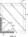
本発明の方法に従って作られた例示的な絶縁グレージングユニットは、図1および9の中の数字6によって一般に示される。絶縁グレージングユニット6は、一般に1対の板ガラス22を間隔を置いた構成で支持し、板ガラス22の間、およびスペーサーアセンブリー8の内側に絶縁チャンバー40を画定するスペーサーアセンブリー8を含む。スペーサーアセンブリー8は少なくとも1つのスペーサーボディ10および第一のシーラント18を含む。この出願の文脈においては、第一のシーラントは、スペーサーの構造要素とガラスの間にシールを形成するシーラントである。スペーサーアセンブリー8は任意に第2のシーラント44を含むことができる。スペーサーボディ10は、組み合わせて使用される様々な任意の要素を含むことができ、種々様々の物質から作られることができる。例えば、スペーサーボディ10は、スペーサーボディ10を板ガラス22へしっかりと取り付けられるために使用される防湿剤および接着剤を含むことができる。発明の例示的な実施態様では、スペーサーボディ10は軟質フォーム物質から形成される。スペーサーボディ10は任意に乾燥剤を有することができる。
DETAILED DESCRIPTION OF THE INVENTION An exemplary insulating glazing unit made in accordance with the method of the present invention is generally indicated by the numeral 6 in FIGS. The insulating glazing unit 6 generally includes a
例示的な実施態様では、スペーサーボディ10は、貯蔵容器24中に保持されて絶縁ガラスメーカーに供給される。貯蔵容器24は柔軟なスペーサーボディ10が乾燥剤を含む場合に、乾燥剤を保存するために密閉してシールされることができる。例えば、スペーサーボディ10は、オハイオ州ケンブリッジのエッジテック アイジーによって連邦に公認された、SUPER SPACERの商標の下で販売されるスペーサーボディのような柔軟なスペーサーボディであることがある。例示的なスペーサーボディ10は米国特許4,831、799に示される。それらの開示は、参照されここに組込まれる。柔軟なスペーサーボディが使用される場合、柔軟なスペーサーボディはコンテナ24内でリールに巻かれ、コイルにされることができる。例示的な実施態様では、スペーサーボディ10は、接着剤14を支持する1対のショルダーの間におかれた金属フォイル防湿層12を有する。接着剤14は、スペーサーボディ10を板ガラス22へしっかりと取り付けるために使用される。例示的なスペーサーボディ10は、ショルダーの下にノッチ16を画定する。スペーサーボディ10は、絶縁エアポケットを画定するショルダーの間に直接配置された長さ方向の開口を画定することができる。開口は、さらにショルダー間の直接の熱の通過を防止する。
In the exemplary embodiment,
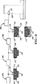
本発明の一体化されたオンラインシーラント適用方法の略図は、図9に示される。一体化されたシーラントの適用により絶縁グレージングユニット6を形成するために、スペーサーボディ10は貯蔵容器24から取り出され、絶縁グレージングユニット6を形成しつつ、ガラスにスペーサーを適用する装置内に置かれる。ストリッパ26は接着層14から保護カバー15を取り除く。その後、スペーサーボディ10は、スペーサーボディ10にシーラント18を適用する装置28と相互作用する。適切なメカニズムが提供され、スペーサーボディ10がシーラントアプリケーター28を通って移動され、シーラント18が適用される。例えば、これらのメカニズムは適切なガイドおよびローラーを含むことができる。この方法の利点は、スペーサーボディ10へのシーラント18の適用を最適化し、エアポケットを防止し、シーラント18を適切な量で、適切な位置に適用するように装置28を構成することができることである。アプリケーター28は、1対の相対して配置されたアプリケーターノズル20を含むことができる。シーラント18は異なるノズル20で、相対して配置されたノッチ16の両方に同時に適用されることができる。図面の中で示されるように、ノズル20は斜めにすることができるし、またはそれらが対面するように直線状にすることができる。別の実施態様では、シーラント18は第1の位置で、第1のノズルで1つの角ノッチ16に適用され、別の角ノッチ16には第2のノズルで、第1の位置の下流の第2の位置で適用されることができる。アプリケーター28にはスペーサーボディ10をガラス22に適用するアプリケーターがともに配置され、それとともに移動する。この位置に配置された時、シーラントがスペーサーボディに適用された後、シーラントが汚染される機会はほとんどはない。シーラントは、さらにガラスと結合される前に冷える時間がほとんどない。
A schematic diagram of the integrated on-line sealant application method of the present invention is shown in FIG. In order to form the insulating glazing unit 6 by the application of an integrated sealant, the
その後、オフ−ラインの貯蔵工程または手による取り扱い工程なしに、スペーサーボディ10は図3に示されるようにガラス22に適用される。新たに適用されたシーラント18は、望ましくない汚染の機会がほとんどなく、ガラスと直ちに結合される。シーラント18の適用は、従来当該技術分野において認識されていない方法で製造工程へ、このように統合される。発明の1つの実施態様では、シーラントを保持するスペーサーボディがガラス22に適用される際に、フレームが形成される。スペーサーボディ10およびシーラント18は、ガラス22の周囲に従う自動設備の使用を介してフレームへ作成されることができる。スペーサーボディ10およびシーラント18は、手動のアプリケーターで、周囲部のフレームへ作成されることもできる。そのような手動のアプリケーターは、ユーザが手動でシーラントを保持するスペーサーボディを扱わずに、ガラスに手動でスペーサーボディを適用することを可能にする。
The
第2の板ガラス22が適用され(図7)、2つの板ガラス22とスペーサーボディ10の間で画定された、絶縁チャンバー40を備えた絶縁グレージングユニット8を作成する。外側に向いたシーラントチャンネル42も、板ガラス22の端から内側にスペーサーボディ10を配置することにより画定されることができる。いくつかの実施態様では、その後、第2のシーラント44が、当該技術分野において公知の技術の様々な方法のうちの任意の方法によりチャンネル42内に配置される。シーラント44はシーラント18と同じシーラントであることができ、または絶縁グレージングユニットの所望の特性に応じて本質的に異なるシーラントであることができる。シーラント18は、絶縁グレージングユニット中でスペーサーボディと板ガラス22の間で密閉されたシールを作成するために、当業者に公知の種々様々のシーラントの任意の物であることができる。非制限的な例を提供する目的のために、シーラント18は、ポリイソブチレン、ホットメルトブチル、ホットメルト物質、UV硬化可能な物質、または硬化してせん断力に耐える構造強度を有する物質であることができる。他の物質が硬化した後に非流動性になるのに対し、これらの物質のうちのいくつかは適用され、冷却された後にも流動性を保持する。この方法により適用されることができる別のタイプのシーラント18は、ガラスと架橋し、シーラントとガラスの間の接着を形成することができるシーラントである。
A
本発明の1つの利点は、シーラントの適用がガラス適用工程から独立し、ガラス22が、スペーサーボディ10へのシーラント18の適用を邪魔しないということである。この方法では、このように両方の工程を独立して最適化することが許容される。別の利点は、シーラント18の温度がスペーサーボディ10への理想的な適用のためにコントロールされることができ、次に、ガラス22の理想的な適用のために異なる温度に変更されることができるということである。いくつかの実施態様では、ユーザーは、図2における高温から、図3における低温にシーラント18を冷却し、シーラント18がガラス22に適用される際にシーラント18内に幾分かの熱が残っていることを望むことがある。スペーサーボディ10にシーラント18が適用される場合、典型的にはシーラント18は外界温度以上に熱される。いくつかのシーラント18では、それがガラスに適用されるまで、その高い温度を維持することが望まれる。他のシーラントでは、シーラント18の温度は、図2の位置から図3の位置へ高くされる必要があることがある。他の実施態様では、ユーザーは、図2の位置から図3の位置まで一定の温度を維持することを望むことがある。これらの実施態様の各々では、適切な冷却/加熱装置29(たとえば、エアナイフまたはアキュムレータまたはヒーター)が、シーラント18によって保持される熱を調節するために使用されることができる。
One advantage of the present invention is that the application of the sealant is independent of the glass application process and the
本発明の別の利点は、シーラント18の一体化されたオンラインの適用が、シーラント18の汚染の機会を最小限にするということである。シーラント18が図2の位置と図3の位置の間に暴露される環境は、理想的なシーラント条件に精密にコントロールされることができる。本発明の方法は、さらに、スペーサーボディがガラス22に適用される前にハンドリングされる際に生ずる従来技術における課題を回避することができる。なぜなら、シーラントの適用とシーラントを保持するスペーサーボディとガラスとの結合の間に手による取り扱いをする必要がないからである。この方法は、さらに貯蔵と輸送中にシーラントが不格好になるという問題を回避する。シーラントが流動性を有する場合、シーラントは貯蔵および輸送中に不格好になる場合がある(それらが流動性を有する物質である場合、および特にそれらが熱いコンテナ中で輸送される場合)。シーラントは、さらに、スペーサーボディに隣接した他のパッケージの重量が加えられた場合、輸送中に不格好になる。
Another advantage of the present invention is that the integrated online application of
独立した実施態様では、本発明は、スペーサーボディ10がガラス22に適用される時に角を形成する新規な方法を提供する。図5および図6の角成形方法は上に記載されたシーラント適用方法とは独立であるが、本発明の方法と組み合わせて使用されることができる。新しい角成形方法は(誇張されて)図5および図6中に示される。図5は、スペーサーフレームのための角位置を示す。アプリケーターが角位置に到着する時に、アプリケーターはスペーサーボディ10にノッチを付け、スペーサーボディ10中に部分的なノッチ30を作成する。ノッチ30は、スペーサーボディ10のショルダー間の厚いインナーボディ部分32のみを通って伸びる。ノッチ30は円形、三角形、長方形、あるいは様々な他の任意の形状であることができる。ボディ10のショルダー領域を部分的にのみノッチ30を通すことによって、ノッチ30はシーラント18の邪魔をせず、図6中に示されるように、スペーサーボディ10が90度に折られる場合、膨らまされた領域34を作る。ボディ10が角の周囲に容易に曲がることを可能にするために、ノッチ30は完全にショルダー領域を通って伸びることができる。シーラント18のふくらみは、スペーサーフレームの角に強いシールを作成するのを支援する。角は伝統的に封鎖するのが最も困難な領域である。部分的なノッチは、角部での増大した量のスペーサーボディ10および角部での増大した量のシーラント18を保証する。
In an independent embodiment, the present invention provides a novel method of forming corners when the
上記では、ある用語は簡潔さ、明瞭さおよび理解のために使用された。そのような用語が記述的な目的に使用され、広く解釈されるように意図されるので、先行技術の要求を越えて不必要な制限がそれから示唆されるべきではない。さらに、発明の記述および実例は例である。また、発明は示され、記載された詳細なものに制限されない。
また本発明の実施態様は以下のものを包含する。
1.(A) 絶縁グレージングユニットの板ガラスの内側表面に結合するように適合された一対の接着剤を有する面を含むスペーサーボディを貯蔵容器中に提供する工程;
(B) 貯蔵容器からスペーサーボディを取り出す工程;
(C) 工程(B)の後に、スペーサーボディにシーラントを適用し、シーラントを保持するスペーサーボディを形成する工程;
(D) 1つの面上にある接着剤で、シーラントを保持するスペーサーボディを第1の板ガラスに結合する工程;および
(E) 工程(C)および工程(D)の後に、シーラントを保持するスペーサーボディからスペーサーフレームを形成する工程;を含み、
工程(C)の後にシーラントを保持するスペーサーボディを手で扱う工程のない、
絶縁グレージングユニットを形成する際に、板ガラスにスペーサーを適用する方法。
2. シーラントを保持するスペーサーボディを板ガラスにアプリケーターヘッドで取り付け、アプリケーターヘッドでスペーサーボディにシーラントを適用する、前記第1項記載の方法。
3. スペーサーボディが貯蔵容器中にコイルとして提供され、工程(B)の間に貯蔵容器からスペーサーボディの少なくとも1部分をほどく工程を更に含む、前記第1項記載の方法。
4. 柔軟で、乾燥剤を含む、フォームベースの物質の形態でスペーサーボディを提供する工程を更に含む、前記第1項記載の方法。
5. 工程(C)が、グレージングユニットの板ガラスに隣接して構成されたスペーサーボディの相対する側に、間隔を置いた配置でシーラントを適用する工程を更に含む、前記第1項記載の方法。
6. 工程(C)の後で、シーラントを保持するスペーサーボディがグレージングユニットの第1の板ガラスに結合される前に、シーラントが冷却される、前記第1項記載の方法。
7. 工程(C)の前に周囲温度以上の温度へシーラントを加熱する工程を含み、シーラントの温度が周囲温度に戻る前に工程(D)を行う、前記第6項記載の方法。
8. 工程(C)の後で、シーラントを保持するスペーサーボディがグレージングユニットの第1の板ガラスに結合される前に、シーラントが温められる、前記第1項記載の方法。
9. 工程(B)の後にシーラントとガラスを結合する工程を更に含む、前記第1項記載の方法。
10. 2枚のガラスとスペーサーボディの間に外側に向いたシーラントチャンネルを形成し、外側に向いたシーラントチャンネルを物質で充填する工程を更に含む、前記第1項記載の方法。
11. (A) 柔軟で、フォーム形態で、乾燥剤を含み、両側に付着した接着剤を有するスペーサーボディを貯蔵容器中に提供する工程;
(B) 貯蔵容器からスペーサーボディの一部を取り出す工程;
(C) 工程(B)の後に、第1の温度でスペーサーボディの相対する側に、接着剤を完全には覆うことなくシーラントを適用し、シーラントを保持するスペーサーボディを形成する工程;
(D) 工程(C)の後に、シーラントを保持するスペーサーボディに第1の板ガラスを接着剤で取り付けてスペーサーフレームを形成し、シーラントの一部が第1の板ガラスと結合し、第1の板ガラスとスペーサーボディの間にシールを形成する工程;および
(E) 第2の板ガラスをシーラントを保持するスペーサーフレームに接着剤で取り付け、シーラントの他の部分が第2の板ガラスとスペーサーフレームの間に密閉されたシールを形成するようにする工程;
を含む、絶縁されたグレージングユニットを形成する方法。
12. 工程(C)と(D)の間に、シーラントを保持するスペーサーボディを手で扱う工程がない、前記第11項記載の方法。
13. 工程(C)と(D)の間に、シーラントを冷却する工程を含む、前記第11項記載の方法。
14. 工程(C)の後に、絶縁されたグレージングユニットのガラスとシーラントを結合する工程を更に含む、前記第11項記載の方法。
15. (A) 絶縁グレージングユニットを作るために適合された自動化装置中にスペーサーボディを提供する工程であって、ここで該スペーサーボディは、絶縁グレージングユニットの板ガラスの内側表面に結合するように適合された接着剤を有する少なくとも2つの面を有し、該接着剤はスペーサーボディを板ガラスの内側表面にしっかりと取り付けるように適合される;
(B) 工程(A)の後にスペーサーボディにシーラントを適用し、複数の板ガラスの内側表面に結合するように適合され、それぞれの面に隣接して配置されたシーラント部分を有する、シーラントを保持するスペーサーボディを形成する工程;
(C) 工程(B)の後に、シーラントを保持するスペーサーボディが接着剤により板ガラスの内側表面に結合され、シーラントを保持するスペーサーボディからスペーサーフレームを形成する工程;ここで工程(B)の後にシーラントを保持するスペーサーボディを手で取り扱う工程がない;および
(D) スペーサーフレームを使用して絶縁グレージングユニットを形成する工程;
を含む、絶縁グレージングユニットを形成する方法。
16. ガラスにシーラントを保持するスペーサーボディを適用しつつ、スペーサーフレームを形成する工程をさらに含む、前記第15項記載の方法。
17. スペーサーボディが貯蔵容器中にコイルとして提供され、工程(A)の前に貯蔵容器からスペーサーボディの少なくとも1部分をほどく工程を更に含む、前記第15項記載の方法。
18. 柔軟で、乾燥剤を含む、フォームベースの物質の形態でスペーサーボディを提供する工程を更に含む、前記第15項記載の方法。
19. 工程(B)の後で工程(C)の前にシーラントを冷却する工程を含む、前記第15項記載の方法。
20. 工程(B)の前に雰囲気温度以上にシーラントを加熱する工程をさらに含み、シーラントが雰囲気温度に戻る前に工程(C)を行う、前記第19項記載の方法。
21. 工程(B)の後で、シーラントを保持するスペーサーボディをグレージングユニットの第1の板ガラスに結合する前に、シーラントを温める工程をさらに含む、前記第15項記載の方法。
22. 外側に向いたシーラントチャンネルを、2枚の板ガラスとスペーサーボディの間に形成し、外側に向いたシーラントチャンネルを物質で充填する工程を更に含む、前記第15項記載の方法。
23. (A) 絶縁グレージングユニットの複数の板ガラスの内側表面に結合するように適合された一対の接着剤を有する面を含むスペーサーボディを貯蔵容器中に提供する工程;
(B) 貯蔵容器からスペーサーボディを取り出す工程;
(C) 工程(B)の後に、スペーサーボディにシーラントを適用し、シーラントを保持するスペーサーボディを形成する工程;
(D) 工程(C)の後に、接着剤で第1の板ガラスにシーラントを保持するスペーサーボディを接着させることにより、第1の板ガラス上に直接スペーサーフレームを形成し、シーラントの一部が第1の板ガラスと結合し、第1の板ガラスとスペーサーボディの間にシールを形成する工程;および
(E) 第2の板ガラスを接着剤でスペーサーフレームに接着し、シーラントの他の部分が第2の板ガラスとスペーサーボディの間にシールを形成する工程;を含む、絶縁グレージングユニットの製造方法。
24. スペーサーボディが貯蔵容器中にコイルとして提供され、工程(B)の間に貯蔵容器からスペーサーボディの少なくとも1部分をほどく工程を更に含む、前記第23項記載の方法。
25. 柔軟で、乾燥剤を含む、フォームベースの物質の形態でスペーサーボディを提供する工程を更に含む、前記第23項記載の方法。
26. 工程(C)が、グレージングユニットの板ガラスに隣接して構成されたスペーサーボディの相対する側に、間隔を置いた配置でシーラントを適用する工程を更に含む、前記第23項記載の方法。
27. 工程(C)の後で、シーラントを保持するスペーサーボディがグレージングユニットの第1の板ガラスに結合される前に、シーラントが冷却される、前記第23項記載の方法。
28. 工程(C)の前に周囲温度以上の温度へシーラントを加熱する工程を含み、シーラントの温度が周囲温度に戻る前に工程(D)を行う、前記第27項記載の方法。
29. 工程(C)の後で、シーラントを保持するスペーサーボディがグレージングユニットの第1の板ガラスに結合される前に、シーラントが温められる、前記第23項記載の方法。
30. 外側に向いたシーラントチャンネルを、2枚の板ガラスとスペーサーボディの間に形成し、外側に向いたシーラントチャンネルを物質で充填する工程を更に含む、前記第23項記載の方法。
31. (A) スペーサーボディを貯蔵容器中に提供する工程;
(B) 貯蔵容器からスペーサーボディを取り出す工程;
(C) 工程(B)の後に、スペーサーボディにシーラントを適用し、シーラントを保持するスペーサーボディを形成する工程;
(D) 工程(C)の後に、接着剤で第1の板ガラスにシーラントを保持するスペーサーボディを接着させることにより、第1の板ガラス上に直接スペーサーフレームを形成し、シーラントの一部が第1の板ガラスと結合し、第1の板ガラスとスペーサーボディの間にシールを形成する工程;および
(E) 第2の板ガラスを接着剤でスペーサーフレームに接着し、シーラントの他の部分が第2の板ガラスとスペーサーボディの間にシールを形成する工程;を含む、絶縁グレージングユニットの製造方法。
32. スペーサーボディが貯蔵容器中にコイルとして提供され、工程(B)の間に貯蔵容器からスペーサーボディの少なくとも1部分をほどく工程を更に含む、前記第31項記載の方法。
33. 柔軟で、乾燥剤を含む、フォームベースの物質の形態でスペーサーボディを提供する工程を更に含む、前記第31項記載の方法。
34. 工程(C)が、グレージングユニットの板ガラスに隣接して構成されたスペーサーボディの相対する側に、間隔を置いた配置でシーラントを適用する工程を更に含む、前記第31項記載の方法。
In the above, certain terms have been used for brevity, clarity and understanding. Since such terms are used for descriptive purposes and are intended to be broadly construed, no unnecessary limitations beyond the requirements of the prior art should then be suggested. Further, the description and illustration of the invention are examples. Moreover, the invention is not limited to the details shown and described.
Embodiments of the present invention include the following.
1. (A) providing a spacer body in the storage container that includes a surface having a pair of adhesives adapted to bond to the inner surface of the glass sheet of the insulating glazing unit;
(B) removing the spacer body from the storage container;
(C) After step (B), applying a sealant to the spacer body to form a spacer body that holds the sealant;
(D) bonding the spacer body holding the sealant to the first glass sheet with an adhesive on one side; and
(E) after step (C) and step (D), forming a spacer frame from a spacer body holding a sealant;
There is no process of handling the spacer body holding the sealant by hand after the process (C).
A method of applying a spacer to a glass sheet when forming an insulating glazing unit.
2. The method according to claim 1, wherein the spacer body holding the sealant is attached to the glass plate with an applicator head, and the sealant is applied to the spacer body with the applicator head.
3. The method of claim 1, further comprising the step of providing the spacer body as a coil in the storage container and unwinding at least a portion of the spacer body from the storage container during step (B).
4). The method of claim 1, further comprising providing the spacer body in the form of a foam-based material that is flexible and includes a desiccant.
5. The method of claim 1, wherein step (C) further comprises applying a sealant in a spaced arrangement to opposite sides of a spacer body configured adjacent to the glazing unit glass sheet.
6). The method of claim 1, wherein after step (C), the sealant is cooled before the spacer body holding the sealant is bonded to the first glass sheet of the glazing unit.
7). The method according to claim 6, further comprising the step of heating the sealant to a temperature equal to or higher than the ambient temperature before the step (C), and performing the step (D) before the temperature of the sealant returns to the ambient temperature.
8). The method of claim 1, wherein after step (C), the sealant is warmed before the spacer body holding the sealant is bonded to the first glass sheet of the glazing unit.
9. The method according to claim 1, further comprising a step of bonding the sealant and the glass after the step (B).
10. The method of claim 1, further comprising forming an outwardly directed sealant channel between the two glasses and the spacer body, and filling the outwardly directed sealant channel with the material.
11. (A) providing a spacer body in a storage container that is flexible, in foam form, includes a desiccant and has an adhesive attached to both sides;
(B) a step of removing a part of the spacer body from the storage container;
(C) after step (B), applying a sealant to the opposite side of the spacer body at a first temperature without completely covering the adhesive to form a spacer body holding the sealant;
(D) After the step (C), the first plate glass is attached to the spacer body holding the sealant with an adhesive to form a spacer frame, and a part of the sealant is bonded to the first plate glass. Forming a seal between the spacer body and the spacer body; and
(E) attaching the second glass sheet to the spacer frame holding the sealant with an adhesive so that the other part of the sealant forms a sealed seal between the second glass sheet and the spacer frame;
Forming an insulated glazing unit.
12 12. The method according to claim 11, wherein there is no step of manually handling the spacer body holding the sealant between steps (C) and (D).
13. The method according to claim 11, comprising a step of cooling the sealant between steps (C) and (D).
14 The method of claim 11, further comprising the step of bonding the glass and sealant of the insulated glazing unit after step (C).
15. (A) Providing a spacer body in an automated apparatus adapted to make an insulating glazing unit, wherein the spacer body is adapted to bond to the inner surface of the glass sheet of the insulating glazing unit. Having at least two sides with an adhesive, the adhesive being adapted to securely attach the spacer body to the inner surface of the glazing;
(B) applying a sealant to the spacer body after step (A) and holding the sealant, adapted to bond to the inner surface of the plurality of glass panes and having a sealant portion disposed adjacent to each face Forming a spacer body;
(C) After step (B), a spacer body holding the sealant is bonded to the inner surface of the glass sheet with an adhesive and forming a spacer frame from the spacer body holding the sealant; here after step (B) No manual handling of the spacer body holding the sealant; and
(D) forming an insulating glazing unit using a spacer frame;
Forming an insulating glazing unit.
16. 16. The method of
17. 16. The method of
18. 16. The method of
19. 16. The method of
20. The method according to claim 19, further comprising heating the sealant to a temperature equal to or higher than the ambient temperature before the step (B), and performing the step (C) before the sealant returns to the ambient temperature.
21. 16. The method of
22. 16. The method of
23. (A) providing a spacer body in a storage container that includes a surface having a pair of adhesives adapted to bond to the inner surface of a plurality of glass panes of an insulating glazing unit;
(B) removing the spacer body from the storage container;
(C) After step (B), applying a sealant to the spacer body to form a spacer body that holds the sealant;
(D) After step (C), a spacer frame is formed directly on the first glass sheet by bonding a spacer body holding the sealant to the first glass sheet with an adhesive, and a part of the sealant is first Forming a seal between the first glass sheet and the spacer body; and
(E) A method of manufacturing an insulating glazing unit, comprising: adhering a second plate glass to a spacer frame with an adhesive, and forming a seal between the second plate glass and the spacer body with another part of the sealant.
24. 24. The method of claim 23, further comprising the step of providing the spacer body as a coil in the storage container and unwinding at least a portion of the spacer body from the storage container during step (B).
25. 24. The method of claim 23, further comprising providing the spacer body in the form of a foam-based material that is flexible and includes a desiccant.
26. 24. The method of claim 23, wherein step (C) further comprises applying a sealant in a spaced arrangement to opposite sides of a spacer body configured adjacent to the glazing unit glass sheet.
27. 24. The method of claim 23, wherein after step (C), the sealant is cooled before the spacer body holding the sealant is bonded to the first glass sheet of the glazing unit.
28. 28. The method of
29. 24. The method of claim 23, wherein after step (C), the sealant is warmed before the spacer body holding the sealant is bonded to the first glass sheet of the glazing unit.
30. 24. The method of claim 23, further comprising forming an outwardly directed sealant channel between the two glass panes and the spacer body, and filling the outwardly directed sealant channel with the material.
31. (A) providing a spacer body in the storage container;
(B) removing the spacer body from the storage container;
(C) After step (B), applying a sealant to the spacer body to form a spacer body that holds the sealant;
(D) After step (C), a spacer frame is formed directly on the first glass sheet by bonding a spacer body holding the sealant to the first glass sheet with an adhesive, and a part of the sealant is first Forming a seal between the first glass sheet and the spacer body; and
(E) A method of manufacturing an insulating glazing unit, comprising: adhering a second plate glass to a spacer frame with an adhesive, and forming a seal between the second plate glass and the spacer body with another part of the sealant.
32. 32. The method of claim 31, further comprising the step of providing the spacer body as a coil in the storage container and unwinding at least a portion of the spacer body from the storage container during step (B).
33. 32. The method of claim 31, further comprising providing the spacer body in the form of a foam-based material that is flexible and includes a desiccant.
34. 32. The method of claim 31, wherein step (C) further comprises applying a sealant in a spaced arrangement to opposite sides of a spacer body configured adjacent to the glazing unit glass sheet.
Claims (5)
(B) 該貯蔵容器から少なくとも一部の該スペーサーボディを取り出す工程;
(C) 工程(B)の後に、該スペーサーボディにシーラントを適用し、シーラントを保持するスペーサーボディを形成する工程;
(D) 1つの面上にある接着剤で、該シーラントを保持するスペーサーボディを第1の板ガラスに結合する工程;および
(E) 工程(C)および工程(D)の後に、該シーラントの一部を該第1の板ガラスと結合し、該第1の板ガラスと該スペーサーボディの間にシールを形成し、該シーラントを保持するスペーサーボディからスペーサーフレームを形成する工程;を含み、
工程(C)の後に該シーラントを保持するスペーサーボディを手で扱う工程がなく、さらに
(F) 他の面上にある接着剤で、該シーラントを保持するスペーサーフレームに、第2の板ガラスを取り付け、シーラントの他の部分が該第2の板ガラスと該スペーサーフレームの間に密閉されたシールを形成する工程;を含む
絶縁グレージングユニットを形成する際に、板ガラスにスペーサーを適用する方法。(A) providing a spacer body including a surface having a pair of adhesives in a storage container;
(B) step of taking at least a portion of the spacer body from the storage container;
After step (C) (B), forming a spacer body to apply the sealant to the spacer body retains the sealant;
(D) an adhesive located on one surface, the spacer body for holding the sealant step to bind to the first glass sheet; after and (E) Step (C) and step (D), of the sealant one Combining a portion with the first glass sheet, forming a seal between the first glass sheet and the spacer body, and forming a spacer frame from the spacer body holding the sealant ;
No step is to deal with the spacer body with the hand holding the sealant after step (C), further
(F) With the adhesive on the other surface, the second plate glass was attached to the spacer frame holding the sealant, and the other part of the sealant was sealed between the second plate glass and the spacer frame. Forming a seal; and applying a spacer to the glass sheet when forming an insulating glazing unit.
(B) 該貯蔵容器から該スペーサーボディの少なくとも一部を取り出す工程;
(C) 工程(B)の後に、第1の温度で該スペーサーボディの相対する側に、該接着剤を完全には覆うことなくシーラントを適用し、シーラントを保持するスペーサーボディを形成する工程;
(D) 工程(C)の後に、該シーラントを保持するスペーサーボディに第1の板ガラスを該接着剤で取り付けてスペーサーフレームを形成し、該シーラントの一部が該第1の板ガラスと結合し、該第1の板ガラスと該スペーサーボディの間にシールを形成する工程;および
(E) 第2の板ガラスをシーラントを保持する該スペーサーフレームに該接着剤で取り付け、該シーラントの他の部分が該第2の板ガラスと該スペーサーフレームの間に密閉されたシールを形成する工程;
を含む、絶縁されたグレージングユニットを形成する方法。(A) a step of providing a spacer body that is a flexible foam and includes a desiccant, wherein the spacer body is a spacer body with adhesive applied on both sides thereof;
Step (B) from said storage container to retrieve at least a portion of the spacer body;
After step (C) (B), on opposite sides of the spacer body at a first temperature, forming a spacer body to apply the sealant without covering completely the adhesive to hold the sealant;
After the step (D) (C), the first glass sheet to the spacer body for holding the sealant to form a spacer frame is attached with the adhesive, a portion of the sealant is bonded to said first glass sheet, step of forming a seal between said first glass sheet and the spacer body; attached in the adhesive and (E) a second glass sheet to the spacer frame to hold the sealant, other parts of the sealant is the first forming a closed seal between the two glass sheets and the spacer frame;
Forming an insulated glazing unit.
(B) 工程(A)の後に該スペーサーボディにシーラントを適用し、複数の板ガラスの内側表面に結合することができ、それぞれの面に隣接して配置されたシーラント部分を有する、シーラントを保持するスペーサーボディを形成する工程;
(C) 工程(B)の後に、該シーラントを保持するスペーサーボディが該接着剤により該板ガラスの内側表面に結合され、該シーラントを保持するスペーサーボディからスペーサーフレームを形成し、シーラントの一部が第1の板ガラスと結合し、該第1の板ガラスと該スペーサーボディの間にシールを形成する工程;ここで工程(B)の後に該シーラントを保持するスペーサーボディを手で取り扱う工程がなく;さらに
(D) 他の面上にある接着剤で、該シーラントを保持するスペーサーフレームに第2の板ガラスを取り付け、シーラントの他の部分が該第2の板ガラスと該スペーサーフレームの間に密閉されたシールを形成することにより該スペーサーフレームを使用して絶縁グレージングユニットを形成する工程;
を含む、絶縁グレージングユニットを形成する方法。(A) Providing a spacer body in an automated apparatus adapted to make an insulating glazing unit, wherein the spacer body is adapted to bond to the inner surface of the glass sheet of the insulating glazing unit. having at least two surfaces with an adhesive, the adhesive can be attached securely the spacer body to the inner surface of the glass sheet;
(B) sealant was applied to the spacer body after step (A), can be coupled to the inner surfaces of the glass sheets, having a sealant portion disposed adjacent each side to hold the sealant Forming a spacer body;
After step (C) (B), the spacer body for holding the sealant is bonded to the inner surface of the glass sheet by the adhesive, a spacer frame formed from a spacer body for holding the sealant, a part of the sealant no step is handled by hand spacer body for holding the sealant after where step (B);; bonded to the first glass sheet to form a seal between the first glass sheet and the spacer body further (D) A seal in which the second plate glass is attached to the spacer frame holding the sealant with an adhesive on the other surface, and the other part of the sealant is sealed between the second plate glass and the spacer frame. Forming an insulating glazing unit using the spacer frame by forming:
Forming an insulating glazing unit.
(B) 該貯蔵容器から少なくとも一部の該スペーサーボディを取り出す工程;
(C) 工程(B)の後に、該スペーサーボディにシーラントを適用し、シーラントを保持するスペーサーボディを形成する工程;
(D) 工程(C)の後に、該接着剤で第1の板ガラスに該シーラントを保持するスペーサーボディを接着させることにより、該第1の板ガラス上に直接スペーサーフレームを形成し、該シーラントの一部が該第1の板ガラスと結合し、該第1の板ガラスと該スペーサーボディの間にシールを形成する工程;および
(E) 第2の板ガラスを該接着剤で該スペーサーフレームに接着し、シーラントの他の部分が該第2の板ガラスと該スペーサーボディの間にシールを形成する工程;を含む、絶縁グレージングユニットの製造方法。(A) providing a spacer body including a surface having an adhesive one pair capable you to bind to the inner surfaces of the glass sheets of the insulating glazing unit during the storage vessel;
(B) step of taking at least a portion of the spacer body from the storage container;
After step (C) (B), forming a spacer body to apply the sealant to the spacer body retains the sealant;
After the step (D) (C), by bonding the spacer body for holding the sealant to the first glass sheet with the adhesive, the directly spacer frame formed on a first glass sheet, of the sealant one parts are bound to the first glass sheet, a step of forming a seal between the first glass sheet and the spacer body; and (E) a second glass sheet is bonded to the spacer frame in the adhesive, sealant another portion of the step of forming a seal between said second glass sheet and the spacer body; including, manufacturing method of the insulating glazing unit.
(B) 該貯蔵容器から少なくとも一部の該スペーサーボディを取り出す工程;
(C) 工程(B)の後に、該スペーサーボディにシーラントを適用し、シーラントを保持するスペーサーボディを形成する工程;
(D) 工程(C)の後に、該接着剤で第1の板ガラスに該シーラントを保持するスペーサーボディを接着させることにより、該第1の板ガラス上に直接スペーサーフレームを形成し、該シーラントの一部が該第1の板ガラスと結合し、該第1の板ガラスと該スペーサーボディの間にシールを形成する工程;および
(E) 第2の板ガラスを該接着剤で該スペーサーフレームに接着し、シーラントの他の部分が該第2の板ガラスと該スペーサーボディの間にシールを形成する工程;を含む、絶縁グレージングユニットの製造方法。(A) providing a spacer body in the storage container;
(B) step of taking at least a portion of the spacer body from the storage container;
After step (C) (B), forming a spacer body to apply the sealant to the spacer body retains the sealant;
After the step (D) (C), by bonding the spacer body for holding the sealant to the first glass sheet with the adhesive, the directly spacer frame formed on a first glass sheet, of the sealant one parts are bound to the first glass sheet, a step of forming a seal between the first glass sheet and the spacer body; and (E) a second glass sheet is bonded to the spacer frame in the adhesive, sealant another portion of the step of forming a seal between said second glass sheet and the spacer body; including, manufacturing method of the insulating glazing unit.
Applications Claiming Priority (3)
| Application Number | Priority Date | Filing Date | Title |
|---|---|---|---|
| US54155204P | 2004-02-04 | 2004-02-04 | |
| US60/541,552 | 2004-02-04 | ||
| PCT/US2005/003759 WO2005078227A1 (en) | 2004-02-04 | 2005-02-04 | A method for forming an insulating glazing unit |
Publications (3)
| Publication Number | Publication Date |
|---|---|
| JP2007520417A JP2007520417A (en) | 2007-07-26 |
| JP2007520417A5 JP2007520417A5 (en) | 2008-03-13 |
| JP4869949B2 true JP4869949B2 (en) | 2012-02-08 |
Family
ID=34860196
Family Applications (1)
| Application Number | Title | Priority Date | Filing Date |
|---|---|---|---|
| JP2006552313A Active JP4869949B2 (en) | 2004-02-04 | 2005-02-04 | Method for forming an insulating glazing unit |
Country Status (17)
| Country | Link |
|---|---|
| US (3) | US7347909B2 (en) |
| EP (2) | EP2439372B1 (en) |
| JP (1) | JP4869949B2 (en) |
| KR (1) | KR101092316B1 (en) |
| CN (1) | CN100594286C (en) |
| AT (1) | ATE542021T1 (en) |
| AU (1) | AU2005213671B2 (en) |
| CA (1) | CA2555798C (en) |
| DK (2) | DK1711677T3 (en) |
| ES (2) | ES2379360T3 (en) |
| HU (1) | HUE039956T2 (en) |
| LT (1) | LT2439372T (en) |
| PL (2) | PL1711677T3 (en) |
| PT (2) | PT1711677E (en) |
| RU (1) | RU2384686C2 (en) |
| SI (1) | SI2439372T1 (en) |
| WO (1) | WO2005078227A1 (en) |
Families Citing this family (26)
| Publication number | Priority date | Publication date | Assignee | Title |
|---|---|---|---|---|
| DE10350312B4 (en) * | 2003-10-28 | 2005-12-01 | Peter Lisec | Method and device for applying an elastoplastic tape in the manufacture of an insulating glass pane |
| KR101092316B1 (en) * | 2004-02-04 | 2011-12-09 | 에지테크 아이지 인코포레이티드 | A method for forming an insulating glazing unit |
| DE102004032023B4 (en) * | 2004-07-01 | 2007-06-06 | Peter Lisec | Method and device for producing an insulating glass pane |
| US9309714B2 (en) | 2007-11-13 | 2016-04-12 | Guardian Ig, Llc | Rotating spacer applicator for window assembly |
| EP2220322B1 (en) * | 2007-11-13 | 2017-10-11 | Guardian IG, LLC | Box spacer with sidewalls |
| WO2009126186A1 (en) | 2008-04-10 | 2009-10-15 | Cardinal Ig Company | Manufacturing of photovoltaic subassemblies |
| IT1391489B1 (en) * | 2008-10-17 | 2011-12-23 | For El S P A | AUTOMATIC MACHINE FOR THE CONTINUOUS EXTRUSION OF THERMOPLASTIC SEALANT ON THE SPACER PROFILE DURING THE DISCONTINUOUS APPLICATION OF THE SAME ON GLASS SHEET AND AUTOMATIC PROCEDURE FOR THE CONTINUOUS EXTRUSION OF THERMOPLASTIC SEALANT ON THE SPACER PROFILE DURING THE DISCONTINUOUS APPLICATION OF THE SAME ON GLASS SHEET. |
| GB0906293D0 (en) | 2009-04-14 | 2009-05-20 | Beresford Gary P | Multiple panel glazing unit |
| WO2011008860A1 (en) * | 2009-07-14 | 2011-01-20 | Infinite Edge Technologies, Llc | Stretched strips for spacer and sealed unit |
| DE102009035002A1 (en) * | 2009-07-24 | 2011-01-27 | Bystronic Lenhardt Gmbh | Method for producing an insulating glass pane |
| CA2813168C (en) * | 2009-09-29 | 2017-11-21 | Nebula Glass International, Inc. d/b/a Glasslam N.G.I., Inc. | Method and apparatus for making insulating translucent panel assemblies |
| WO2011156722A1 (en) | 2010-06-10 | 2011-12-15 | Infinite Edge Technologies, Llc | Window spacer applicator |
| US9228389B2 (en) | 2010-12-17 | 2016-01-05 | Guardian Ig, Llc | Triple pane window spacer, window assembly and methods for manufacturing same |
| WO2012088541A2 (en) | 2010-12-23 | 2012-06-28 | Saint-Gobain Performance Plastics Corporation | Structural glazing spacer |
| KR101203829B1 (en) | 2011-04-05 | 2012-11-21 | (주)리노테크 | a combine device for prevent insulating and dew forms of triple glass |
| DE102011115911A1 (en) | 2011-10-14 | 2013-04-18 | Schollglas Holding- und Geschäftsführungsgesellschaft mbH | Spacer profile for insulating glass panel, has side wall portion that is provided with primary region which opens into outer wall, and secondary region which is merged with the pressure adhesive coated portion |
| EP3354836A1 (en) | 2012-05-29 | 2018-08-01 | Quanex IG Systems, Inc. | Spacer for insulating glazing unit |
| US9260907B2 (en) | 2012-10-22 | 2016-02-16 | Guardian Ig, Llc | Triple pane window spacer having a sunken intermediate pane |
| US9689196B2 (en) | 2012-10-22 | 2017-06-27 | Guardian Ig, Llc | Assembly equipment line and method for windows |
| CN203334895U (en) * | 2013-05-22 | 2013-12-11 | 辽宁双强塑胶科技发展股份有限公司 | Spacing sealing strip for hollow glass, hollow glass and window |
| US9266141B2 (en) | 2013-09-10 | 2016-02-23 | Awi Licensing Company | System for applying a coating to a workpiece |
| EA033838B1 (en) * | 2014-01-08 | 2019-12-02 | Лисец Аустриа Гмбх | Method for coating side faces of spacers for insulating glass with an adhesive material |
| WO2015116898A1 (en) | 2014-02-03 | 2015-08-06 | Peter Petit | Compliant hermetic seal system for flat glass panel assembly |
| US10526836B2 (en) | 2017-01-30 | 2020-01-07 | GS Research LLC | Adhesive-attached window glazing assembly, multi-glazed window assembly and method therefor |
| EP3511507B1 (en) * | 2018-01-11 | 2021-07-07 | Prowerb AG | Compound glass panel and method for producing same |
| US10982485B2 (en) * | 2018-11-02 | 2021-04-20 | Saint-Gobain Glass France | Installation system for fabricating multiple glazing units and method thereof |
Citations (1)
| Publication number | Priority date | Publication date | Assignee | Title |
|---|---|---|---|---|
| GB2045229A (en) * | 1979-02-15 | 1980-10-29 | Kaeuferle Werner | Method of, and apparatus for producing a composite sheet |
Family Cites Families (35)
| Publication number | Priority date | Publication date | Assignee | Title |
|---|---|---|---|---|
| US3399294A (en) * | 1966-01-24 | 1968-08-27 | Richard R. Thieben | Heated insulated glass window structure |
| US3759771A (en) | 1971-04-26 | 1973-09-18 | W Battersby | Method of making double glazing unit |
| DE2214175B1 (en) | 1972-03-23 | 1973-08-23 | Lenhardt, Karl, 7531 Hamberg | DEVICE FOR EXPRESSING KITTMASSES FROM THE NOZZLE OF A FRAME LEG TRANSFER MACHINE FOR THE INSULATING GLASS FACTORY |
| US4431691A (en) | 1979-01-29 | 1984-02-14 | Tremco, Incorporated | Dimensionally stable sealant and spacer strip and composite structures comprising the same |
| DE2905841C2 (en) | 1979-02-15 | 1984-04-19 | Josef Käuferle KG Stahlbau, 8890 Aichach | Method and plant for the production of a composite panel |
| DE8004362U1 (en) | 1980-02-19 | 1980-05-29 | Saar-Gummiwerk Gmbh, 6619 Bueschfeld | INSULATED GLASS PANEL |
| US5105591A (en) * | 1980-04-03 | 1992-04-21 | Glass Equipment Development, Inc. | Spacer frame for an insulating glass panel and method of making the same |
| AT390433B (en) * | 1986-09-01 | 1990-05-10 | Lisec Peter | DEVICE FOR APPLYING FLEXIBLE SPACERS |
| US5007217A (en) * | 1986-09-22 | 1991-04-16 | Lauren Manufacturing Company | Multiple pane sealed glazing unit |
| CA1285177C (en) * | 1986-09-22 | 1991-06-25 | Michael Glover | Multiple pane sealed glazing unit |
| EP0299496B1 (en) * | 1987-07-17 | 1994-04-13 | Asahi Glass Company Ltd. | Electrolytic capacitor |
| US4950344A (en) * | 1988-12-05 | 1990-08-21 | Lauren Manufacturing Company | Method of manufacturing multiple-pane sealed glazing units |
| CH681102A5 (en) * | 1990-08-10 | 1993-01-15 | Geilinger Ag | |
| DE4029669C1 (en) * | 1990-09-19 | 1991-07-18 | Lenhardt Maschinenbau Gmbh, 7531 Neuhausen, De | |
| CN2194969Y (en) * | 1994-04-11 | 1995-04-19 | 李宝骏 | Decompression type single-frame double glazing window |
| US5888341A (en) * | 1994-05-26 | 1999-03-30 | Lafond; Luc | Apparatus for the automated application of spacer material |
| DE9416966U1 (en) | 1994-10-24 | 1995-01-12 | Lenhardt Maschinenbau | Device for coating spacer frames for insulating glass panes on both sides with an adhesive and sealing compound |
| US5932062A (en) * | 1995-10-25 | 1999-08-03 | Manser; Russell D. | Automated sealant applicator |
| ES2166984T3 (en) * | 1996-11-18 | 2002-05-01 | Luc Lafond | APPARATUS FOR THE AUTOMATED APPLICATION OF SEPARATING MATERIAL AND METHOD OF USING THE SAME. |
| MXPA99005203A (en) * | 1996-12-05 | 2006-07-18 | Sashlite Llc | Integrated multipane window unit and sash. |
| CA2200024C (en) * | 1997-03-14 | 2001-05-22 | Stephen Field | Manufacture of insulating glass units |
| DE19881385D2 (en) * | 1997-09-25 | 2000-07-13 | Caprano & Brunnhofer | Spacer profile for insulating washer unit |
| US6434910B1 (en) * | 1999-01-14 | 2002-08-20 | Afg Industries, Inc. | Rubber core spacer with central cord |
| CN100352783C (en) * | 1999-09-01 | 2007-12-05 | Prc-迪索托国际公司 | Insulating glass unit with structural primary sealant system |
| CN2409314Y (en) * | 1999-10-16 | 2000-12-06 | 杨友靠 | Vacuum sound insulation double-layer glass |
| FR2807783B1 (en) * | 2000-04-13 | 2002-12-20 | Saint Gobain Vitrage | INSULATING GLAZING AND MANUFACTURING METHOD THEREOF |
| DE10023541C2 (en) * | 2000-05-13 | 2002-09-19 | Bayer Isolierglas & Maschtech | Insulating glass pane with single panes and with a spacer profile |
| US6630028B2 (en) * | 2000-12-08 | 2003-10-07 | Glass Equipment Development, Inc. | Controlled dispensing of material |
| DE10212359B4 (en) | 2002-03-20 | 2005-10-06 | Peter Lisec | Method and device for machine application of a spacer strip on a glass pane |
| US6926782B2 (en) * | 2002-06-27 | 2005-08-09 | Glass Equipment Development, Inc. | Method and apparatus for processing sealant of an insulating glass unit |
| DE10250052A1 (en) * | 2002-10-25 | 2004-05-13 | Erbslöh Aluminium Gmbh | Spacer for panes of multiple isoler glass |
| DE10350312B4 (en) | 2003-10-28 | 2005-12-01 | Peter Lisec | Method and device for applying an elastoplastic tape in the manufacture of an insulating glass pane |
| KR101092316B1 (en) * | 2004-02-04 | 2011-12-09 | 에지테크 아이지 인코포레이티드 | A method for forming an insulating glazing unit |
| DE102004032023B4 (en) * | 2004-07-01 | 2007-06-06 | Peter Lisec | Method and device for producing an insulating glass pane |
| ITTV20040117A1 (en) * | 2004-10-20 | 2005-01-20 | For El Base Di Vianello Fortun | AUTOMATIC MACHINE FOR THE APPLICATION OF SPACER PROFILE ON GLASS SHEET AND AUTOMATIC PROCEDURE FOR THE APPLICATION OF SPACER PROFILE ON GLASS SHEET. |
-
2005
- 2005-02-04 KR KR1020067015756A patent/KR101092316B1/en active IP Right Grant
- 2005-02-04 DK DK05712985.0T patent/DK1711677T3/en active
- 2005-02-04 CN CN200580004034A patent/CN100594286C/en active Active
- 2005-02-04 PT PT05712985T patent/PT1711677E/en unknown
- 2005-02-04 US US11/051,525 patent/US7347909B2/en active Active
- 2005-02-04 RU RU2006127550/03A patent/RU2384686C2/en active
- 2005-02-04 CA CA2555798A patent/CA2555798C/en active Active
- 2005-02-04 ES ES05712985T patent/ES2379360T3/en active Active
- 2005-02-04 WO PCT/US2005/003759 patent/WO2005078227A1/en active Application Filing
- 2005-02-04 AU AU2005213671A patent/AU2005213671B2/en active Active
- 2005-02-04 EP EP11009296.2A patent/EP2439372B1/en active Active
- 2005-02-04 PT PT11009296T patent/PT2439372T/en unknown
- 2005-02-04 DK DK11009296.2T patent/DK2439372T3/en active
- 2005-02-04 AT AT05712985T patent/ATE542021T1/en active
- 2005-02-04 ES ES11009296.2T patent/ES2688795T3/en active Active
- 2005-02-04 SI SI200532228T patent/SI2439372T1/en unknown
- 2005-02-04 JP JP2006552313A patent/JP4869949B2/en active Active
- 2005-02-04 EP EP05712985A patent/EP1711677B1/en not_active Revoked
- 2005-02-04 PL PL05712985T patent/PL1711677T3/en unknown
- 2005-02-04 PL PL11009296T patent/PL2439372T3/en unknown
- 2005-02-04 LT LTEP11009296.2T patent/LT2439372T/en unknown
- 2005-02-04 HU HUE11009296A patent/HUE039956T2/en unknown
-
2008
- 2008-01-30 US US12/022,591 patent/US8043455B2/en active Active
-
2011
- 2011-10-25 US US13/280,706 patent/US8617332B2/en active Active
Patent Citations (1)
| Publication number | Priority date | Publication date | Assignee | Title |
|---|---|---|---|---|
| GB2045229A (en) * | 1979-02-15 | 1980-10-29 | Kaeuferle Werner | Method of, and apparatus for producing a composite sheet |
Also Published As
Similar Documents
| Publication | Publication Date | Title |
|---|---|---|
| JP4869949B2 (en) | Method for forming an insulating glazing unit | |
| JP2007520417A5 (en) | ||
| RU2267001C2 (en) | Isolating glass pack, method of production the same and profile forming distance piece of the glass pack | |
| US3832254A (en) | Method of making a multiple glazed unit having a thermoplastic,spacer-dehydrator element | |
| ES2300495T3 (en) | INSULATING GLASS AND ITS MANUFACTURING PROCEDURE. | |
| WO2002014640A1 (en) | Double glazing | |
| JP2005508280A5 (en) | ||
| WO2010011307A2 (en) | Glass block with low-e center lite | |
| CA3123203A1 (en) | Igu cooling assembly and method of operation | |
| EP3414417B1 (en) | Vacuum insulating glass window unit including edge seal and/or method of making the same | |
| HU231318B1 (en) | Thermal insulation glazing panel | |
| WO2020261166A1 (en) | Heat-insulating glass panel | |
| CN114364857A (en) | Insulating glass panel | |
| JPS6382908A (en) | Heat sealing device |
Legal Events
| Date | Code | Title | Description |
|---|---|---|---|
| A521 | Request for written amendment filed |
Free format text: JAPANESE INTERMEDIATE CODE: A523 Effective date: 20080128 |
|
| A621 | Written request for application examination |
Free format text: JAPANESE INTERMEDIATE CODE: A621 Effective date: 20080128 |
|
| A131 | Notification of reasons for refusal |
Free format text: JAPANESE INTERMEDIATE CODE: A131 Effective date: 20110530 |
|
| A521 | Request for written amendment filed |
Free format text: JAPANESE INTERMEDIATE CODE: A523 Effective date: 20110825 |
|
| TRDD | Decision of grant or rejection written | ||
| A01 | Written decision to grant a patent or to grant a registration (utility model) |
Free format text: JAPANESE INTERMEDIATE CODE: A01 Effective date: 20111024 |
|
| A01 | Written decision to grant a patent or to grant a registration (utility model) |
Free format text: JAPANESE INTERMEDIATE CODE: A01 |
|
| A61 | First payment of annual fees (during grant procedure) |
Free format text: JAPANESE INTERMEDIATE CODE: A61 Effective date: 20111116 |
|
| R150 | Certificate of patent or registration of utility model |
Ref document number: 4869949 Country of ref document: JP Free format text: JAPANESE INTERMEDIATE CODE: R150 Free format text: JAPANESE INTERMEDIATE CODE: R150 |
|
| FPAY | Renewal fee payment (event date is renewal date of database) |
Free format text: PAYMENT UNTIL: 20141125 Year of fee payment: 3 |
|
| R250 | Receipt of annual fees |
Free format text: JAPANESE INTERMEDIATE CODE: R250 |
|
| S533 | Written request for registration of change of name |
Free format text: JAPANESE INTERMEDIATE CODE: R313533 |
|
| R350 | Written notification of registration of transfer |
Free format text: JAPANESE INTERMEDIATE CODE: R350 |
|
| R250 | Receipt of annual fees |
Free format text: JAPANESE INTERMEDIATE CODE: R250 |
|
| R250 | Receipt of annual fees |
Free format text: JAPANESE INTERMEDIATE CODE: R250 |
|
| R250 | Receipt of annual fees |
Free format text: JAPANESE INTERMEDIATE CODE: R250 |
|
| R250 | Receipt of annual fees |
Free format text: JAPANESE INTERMEDIATE CODE: R250 |
|
| R250 | Receipt of annual fees |
Free format text: JAPANESE INTERMEDIATE CODE: R250 |
|
| R250 | Receipt of annual fees |
Free format text: JAPANESE INTERMEDIATE CODE: R250 |
|
| R250 | Receipt of annual fees |
Free format text: JAPANESE INTERMEDIATE CODE: R250 |
|
| R250 | Receipt of annual fees |
Free format text: JAPANESE INTERMEDIATE CODE: R250 |
|
| R250 | Receipt of annual fees |
Free format text: JAPANESE INTERMEDIATE CODE: R250 |