EP3318666A1 - Knitted fabric and method for knitting same - Google Patents
Knitted fabric and method for knitting same Download PDFInfo
- Publication number
- EP3318666A1 EP3318666A1 EP16817975.2A EP16817975A EP3318666A1 EP 3318666 A1 EP3318666 A1 EP 3318666A1 EP 16817975 A EP16817975 A EP 16817975A EP 3318666 A1 EP3318666 A1 EP 3318666A1
- Authority
- EP
- European Patent Office
- Prior art keywords
- top portion
- knitting
- knitted fabric
- knitted
- base
- Prior art date
- Legal status (The legal status is an assumption and is not a legal conclusion. Google has not performed a legal analysis and makes no representation as to the accuracy of the status listed.)
- Granted
Links
Images




Classifications
-
- D—TEXTILES; PAPER
- D04—BRAIDING; LACE-MAKING; KNITTING; TRIMMINGS; NON-WOVEN FABRICS
- D04B—KNITTING
- D04B21/00—Warp knitting processes for the production of fabrics or articles not dependent on the use of particular machines; Fabrics or articles defined by such processes
- D04B21/10—Open-work fabrics
-
- D—TEXTILES; PAPER
- D04—BRAIDING; LACE-MAKING; KNITTING; TRIMMINGS; NON-WOVEN FABRICS
- D04B—KNITTING
- D04B21/00—Warp knitting processes for the production of fabrics or articles not dependent on the use of particular machines; Fabrics or articles defined by such processes
- D04B21/06—Patterned fabrics or articles
-
- D—TEXTILES; PAPER
- D04—BRAIDING; LACE-MAKING; KNITTING; TRIMMINGS; NON-WOVEN FABRICS
- D04B—KNITTING
- D04B21/00—Warp knitting processes for the production of fabrics or articles not dependent on the use of particular machines; Fabrics or articles defined by such processes
- D04B21/06—Patterned fabrics or articles
- D04B21/08—Patterned fabrics or articles characterised by thread material
-
- D—TEXTILES; PAPER
- D04—BRAIDING; LACE-MAKING; KNITTING; TRIMMINGS; NON-WOVEN FABRICS
- D04B—KNITTING
- D04B21/00—Warp knitting processes for the production of fabrics or articles not dependent on the use of particular machines; Fabrics or articles defined by such processes
- D04B21/10—Open-work fabrics
- D04B21/12—Open-work fabrics characterised by thread material
-
- D—TEXTILES; PAPER
- D10—INDEXING SCHEME ASSOCIATED WITH SUBLASSES OF SECTION D, RELATING TO TEXTILES
- D10B—INDEXING SCHEME ASSOCIATED WITH SUBLASSES OF SECTION D, RELATING TO TEXTILES
- D10B2401/00—Physical properties
- D10B2401/20—Physical properties optical
-
- D—TEXTILES; PAPER
- D10—INDEXING SCHEME ASSOCIATED WITH SUBLASSES OF SECTION D, RELATING TO TEXTILES
- D10B—INDEXING SCHEME ASSOCIATED WITH SUBLASSES OF SECTION D, RELATING TO TEXTILES
- D10B2403/00—Details of fabric structure established in the fabric forming process
- D10B2403/01—Surface features
- D10B2403/011—Dissimilar front and back faces
- D10B2403/0113—One surface including hollow piping or integrated straps, e.g. for inserts or mountings
-
- D—TEXTILES; PAPER
- D10—INDEXING SCHEME ASSOCIATED WITH SUBLASSES OF SECTION D, RELATING TO TEXTILES
- D10B—INDEXING SCHEME ASSOCIATED WITH SUBLASSES OF SECTION D, RELATING TO TEXTILES
- D10B2403/00—Details of fabric structure established in the fabric forming process
- D10B2403/01—Surface features
- D10B2403/011—Dissimilar front and back faces
- D10B2403/0114—Dissimilar front and back faces with one or more yarns appearing predominantly on one face, e.g. plated or paralleled yarns
-
- D—TEXTILES; PAPER
- D10—INDEXING SCHEME ASSOCIATED WITH SUBLASSES OF SECTION D, RELATING TO TEXTILES
- D10B—INDEXING SCHEME ASSOCIATED WITH SUBLASSES OF SECTION D, RELATING TO TEXTILES
- D10B2403/00—Details of fabric structure established in the fabric forming process
- D10B2403/02—Cross-sectional features
-
- D—TEXTILES; PAPER
- D10—INDEXING SCHEME ASSOCIATED WITH SUBLASSES OF SECTION D, RELATING TO TEXTILES
- D10B—INDEXING SCHEME ASSOCIATED WITH SUBLASSES OF SECTION D, RELATING TO TEXTILES
- D10B2403/00—Details of fabric structure established in the fabric forming process
- D10B2403/02—Cross-sectional features
- D10B2403/021—Lofty fabric with equidistantly spaced front and back plies, e.g. spacer fabrics
- D10B2403/0213—Lofty fabric with equidistantly spaced front and back plies, e.g. spacer fabrics with apertures, e.g. with one or more mesh fabric plies
-
- Y—GENERAL TAGGING OF NEW TECHNOLOGICAL DEVELOPMENTS; GENERAL TAGGING OF CROSS-SECTIONAL TECHNOLOGIES SPANNING OVER SEVERAL SECTIONS OF THE IPC; TECHNICAL SUBJECTS COVERED BY FORMER USPC CROSS-REFERENCE ART COLLECTIONS [XRACs] AND DIGESTS
- Y02—TECHNOLOGIES OR APPLICATIONS FOR MITIGATION OR ADAPTATION AGAINST CLIMATE CHANGE
- Y02P—CLIMATE CHANGE MITIGATION TECHNOLOGIES IN THE PRODUCTION OR PROCESSING OF GOODS
- Y02P70/00—Climate change mitigation technologies in the production process for final industrial or consumer products
- Y02P70/50—Manufacturing or production processes characterised by the final manufactured product
- Y02P70/62—Manufacturing or production processes characterised by the final manufactured product related technologies for production or treatment of textile or flexible materials or products thereof, including footwear
Definitions
- the present invention relates to a knitted fabric having ridge portions formed thereon along a knitting direction and a method of knitting such a fabric. More particularly, the present invention relates to a knitted fabric knitted so that the color of the knitted fabric which is visually recognized by an observer who looks at the knitted fabric from a direction intersecting the knitting direction is changed in accordance with the position of the observer, and a method of knitting such a fabric.
- a knitted fabric to allow clothes or the like to have an excellent, beautiful appearance or liveness has been actively developed.
- a knitted fabric is provided with a color effect which is produced by a method such as using a plurality of yarns having different colors or made of different materials, combining structures, or using a mesh design or the like, and clothes or the like using such a knitted fabric exhibit an excellent, beautiful appearance or liveness caused by the color effect provided on the knitted fabric.
- a knitted fabric provided with a color effect for example, a knitted fabric provided with a color effect called "iridescence" (Japanese Unexamined Patent Application Publication No. 2003-41465 ) and a knitted or woven fabric provided with a color effect which is produced by decorating the surface of the fabric with an uneven pattern (Japanese Unexamined Patent Application Publication No. 2013-124419 ) have been proposed.
- the conventional knitted fabric disclosed in Japanese Unexamined Patent Application Publication No. 2003-41465 is produced by knitting a fabric with yarns which can be dyed in different colors by dyeing alternately using different dying methods or different dyes, and then dying the knitted fabric by alternately using the different dying methods or different dyes so that the portions dyed by the different methods appear on the surface of the knitted fabric with an almost equal area. Because of having the portions dyed by the different methods with an equal area, the knitted fabric exhibits an iridescent color effect.
- the conventional knitted or woven fabric disclosed in Japanese Unexamined Patent Application Publication No. 2013-124419 is a composite fabric composed of an upper fabric and a lower fabric, and has a single-layer structure portion and a double-layer hollow structure portion formed alternately thereon, the upper fabric and the lower fabric being combined together at the single-layer structure portion, and the upper fabric and the lower fabric being separated from each other at the double-layer hollow structure portion.
- the double-layer hollow structure portion in the lower fabric uses a heat-shrinkable fiber yarn, and, in producing the knitted or woven fabric, the double-layer hollow structure portion in the lower fabric is shrunk by thermal processing and thereby the double-layer hollow structure portion in the upper fabric is raised to form a ridge, whereby the surface of the knitted or woven fabric is decorated with an uneven pattern.
- yarns of different colors are arranged in right and left surfaces that constitute the ridge of the upper fabric so that the observer can visually recognize different colors between when looking at the knitted or woven fabric from one surface side and when looking at the knitted or woven fabric from the other surface side, which exhibits a color effect.
- both of the above-described conventional arts provide a knitted fabric with a color effect. Therefore, clothes or the like using such a knitted fabric can exhibit an extraordinary, beautiful appearance or liveness because the knitted fabric looks different when the position of the observer relative to the knitted fabric is changed by a motion of the wearer.
- the above-described conventional knitted fabric requires performing at least two dyeing steps after the fabric is knitted. Therefore, the production process for the knitted fabric is complex and takes much time, which increases the production cost. Further, the knitting yarns to be used for the knitted fabric have to be able to be dyed in different colors; therefore, there is a problem that the knitting yarns are limited in kind.
- the above-described conventional knitted or woven fabric has the ridges that are the double-layer hollow structure portions in the upper fabric raised by heat shrinkage of the double-layer hollow structure portions in the lower fabric.
- These ridges cannot be freely controlled in shape, and therefore the ridges are non-uniform in shape. Accordingly, for example, if the top portions of the ridges are different in position, on some ridges, right and left surfaces thereof have different colors arranged thereon, whereas on other ridges, a color supposed to be arranged only on one surface thereof is arranged on a part of the other surface thereof. Therefore, there is a problem that, when the fabric is looked at from the other surface side, it lacks uniformity because the color supposed to be arranged on the one surface is visually recognized on a part of the other surface, and it is therefore difficult to obtain a sufficient color effect.
- the ridges merely result from parts of the upper fabric being raised; therefore, it cannot be said that the ridges per se have high shape stability. Therefore, the ridges are easily transformed in shape when an external force is applied thereto. Accordingly, if this knitted or woven fabric is used for clothes or the like, there is a problem that the ridges are transformed in shape when an external force is applied thereto by a motion of the wearer, and therefore the clothes or the like have trouble exhibiting an expected color effect.
- the conventional knitted or woven fabric has the problem that it is difficult to exhibit a color effect; therefore, even if it is used for clothes or the like, the clothes or the like are not necessarily provided with a sufficient beauty or liveness.
- the present invention has been achieved in view of the above-described circumstances, and an object thereof is to provide a kitted fabric which does not particularly require knitting yarns to be used therefor to be limited in kind, can be produced at low cost, and can exhibit a stable color effect, and a method of knitting such a fabric.
- the present invention for solving the above-described problems, relates to a knitted fabric having a base and a plurality of ridge portions formed in parallel to each other along a knitting direction on the base, the ridge portions each including a top portion and two side wall portions, the top portion being formed by a stitch row extending along the knitting direction, the two side wall portions each being formed by a stitch row extending in the knitting direction and knitted such that it is knitted in the base at the base side thereof and engaged with the top portion at the top portion side thereof to couple the top portion to the base, at least one of the top and two side wall portions having a different color arranged thereon from the others of the top portion and two side wall portions.
- the top portion has arranged thereon a color different from a color arranged on the two side wall portions
- the color arranged on the top portion is visually recognized
- the color arranged on the top portion is visually recognized, whereas when the knitted fabric is looked at from the direction intersecting the knitting direction, the color arranged on the top portion as well as the color arranged on the two side wall portions are visually recognized.
- the top portion and one of the side wall portions have arranged thereon a color different from a color arranged on the other of the side wall portions, when the knitted fabric is looked at from the one side wall portion side, the color arranged on the top portion and the one side wall portion is visually recognized, whereas when the knitted fabric is looked at from the other side wall portion side, the color arranged on the other side wall portion is visually recognized.
- the color arranged on the top portion is visually recognized.
- the color arranged on the top portion as well as the color arranged on the one side wall portion are visually recognized, whereas when the knitted fabric is looked at from the other side wall portion side, the color arranged on the top portion as well as the color arranged on the other side wall portion are visually recognized.
- this knitted fabric exhibits a color effect such that the color of the knitted fabric which is visually recognized by an observer who looks at the knitted fabric is changed in accordance with the position of the observer.
- the ridge portion per se has high shape stability and it is less likely to be transformed in shape even when an external force is applied thereto. Therefore, the degree of the color effect of the knitted fabric is less likely to be influenced by the manner of use, and therefore the color effect can be sufficiently exhibited.
- the top portion is formed by at least two chain-stitch rows coupled to each other by a coupling yarn, each of the two side wall portions is formed by a chain-stitch row, and the chain-stitch rows of the side wall portions are engaged with the top portion in a state where loops formed on the top portion sides thereof are inserted in the chain-stitch rows of the top portion.
- the knitted fabric can be preferably knitted by a fabric knitting method which uses a knitting machine to knit a knitted fabric having a base and a plurality of ridge portions formed in parallel to each other along a knitting direction on the base, the ridge portions each including a top portion and two side wall portions coupling the top portion to the base, the knitting machine including at least one pair of needle beds having a plurality of knitting needles and facing each other, and a feed mechanism feeding a knitting yarn to the knitting needles, the method including:
- the base and the ridge portions can be formed by knitting chain-stitch rows at the time of knitting. Therefore, as compared with a case where ridges are formed by performing a certain process after knitting as in the conventional method, the ridge portions are less likely to be non-uniform in shape, and therefore the problem that the color effect is not sufficiently exhibited due to nonuniformity in shape of the ridge portions can be solved. Further, this method does not require a dyeing step after knitting, and therefore an increase in cost can be suppressed.
- the knitting yarns to be used therefor are not particularly limited in kind and can be freely selected for use from filament yarns and spun yarns.
- the coupling yarn may be extended between a part of the top portion of each ridge portion and parts of the top portions of other ridge portions adjacent thereto to form a mesh portion.
- the ridge portions can have more improved shape stability.
- the mesh portion being formed causes the ridge portions to be visually recognized through openings of the mesh portion; therefore, as compared with the case where no mesh portion is formed, it is possible to express a complicated pattern.
- the above knitted fabric may have formed thereon a knitted area having at least one cut (opening), the knitted area being knitted to couple a part of the top portion of each ridge portion to parts of the top portions of other ridge portions adjacent thereto.
- the ridge portions can have improved shape stability and the color effect can be stably exhibited.
- the knitted fabric can show a complicated pattern on the surface thereof.
- the base may have at least one stitch row formed therein between each ridge portion and other ridge portions adjacent thereto.
- each ridge portion is spaced apart from the ridge portions adjacent thereto, and therefore the space between the ridge portions is made wider. Therefore, the ranges of the position of the observer which allow the side wall portions to be visually recognized are changed, which allows the color effect to be exhibited differently from the case where the space between the ridge portions is narrow.
- making the space between the ridge portions excessively wide could make the ranges of the position of the observer which allow the side wall portions to be visually recognized too small to sufficiently exhibit the color effect, or could cause the base to be visually recognized so much that the beautiful appearance of the knitted fabric is impaired.
- the number of stitch rows to be formed is adjusted so that the space between the ridge portions is approximately 1.5 mm to 4 mm (which is equivalent to approximately 3 to 5 knitting needles).
- the base may be formed in a mesh pattern and may use a transparent yarn for the knitting yarn therefor. Forming the base in a mesh pattern enables reduction of the weight of the knitted fabric and, when such a knitted fabric is used for clothes or the like, the clothes or the like can have high air permeability. Further, using a transparent yarn for the knitting yarn for the base makes the base inconspicuous and accentuates the colors of the ridge portions, which enhances the color effect produced by arranging different colors on the top portion and two side wall portions constituting the ridge portion.
- the knitted fabric according to the present invention does not particularly require the knitting yarns to be used therefor to be limited in kind, reduces production costs, and nevertheless can stably exhibit an enhanced color effect.
- this knitted fabric is used for clothes or the like, the knitted fabric can provide the clothes or the like with an extremely excellent, beautiful appearance or liveness.
- the fabric knitting method according to the present invention it is possible to make the ridge portions less likely to be non-uniform in shape; therefore, it is possible to knit a fabric which sufficiently exhibits a color effect.
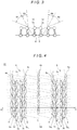
- Fig. 1 shows details of a structure of a warp-knitted fabric 1 according to a first embodiment
- Fig. 2 is a sectional view taken along the line A-A in Fig. 1
- the warp-knitted fabric 1 consists of a base 2 and ridge portions 6 formed along a knitting direction, each ridge portion 6 being composed of a top portion 3 and two side wall portions 4, 5 respectively formed at both sides of the top portion 3.
- the top portion 3 is formed by two chain-stitch rows 3a, 3b coupled to each other by a coupling yarn 3c, and the side wall portions 4, 5 are formed by chain-stitch rows 4a, 5a having loops 4a 1 , 5a 1 , which are described later, engaged with the two chain-stitch rows 3a, 3b, respectively.
- the base 2 is composed of chain-stitch rows 2a, 2b and coupling portions 2d formed between the ridge portions 6, the chain-stitch rows 2a, 2b respectively having the chain-stitch rows 4a, 5a of the side wall portions 4, 5 connected thereto, and each coupling portion 2d being formed by a coupling yarn 2c coupling the chain-stitch rows 2a, 2b to each other.
- the chain-stitch rows 3a, 3b constituting the top portion 3 and the chain stitch rows 4a, 5a constituting the side wall portions 4, 5 are indicated by solid lines
- the coupling yarn 3c of the top portion 3 is indicated by broken lines
- the coupling yarn 2c of the base 2 is indicated by dotted lines
- illustration of the chain-stitch rows 2a, 2b of the base 2 is omitted.
- a knitting yarn of a first color is used for the two chain-stitch rows 3a, 3b constituting the top portion 3
- a knitting yarn of a second color is used for the chain-stitch row 4a constituting the side wall portion 4
- a knitting yarn of a third color is used for the chain-stitch row 5a constituting the side wall portion 5
- a transparent knitting yarn is used for the chain-stitch rows 2a, 2b constituting the base 2 and the coupling yarns 2c, 3c.
- chain-stitch rows 2a, 2b constituting the base 2 may respectively use colored yarns of the same colors as those of the chain-stitch rows 4a, 5a of the side wall portions 4, 5 connected thereto, and the coupling yarn 3c of the top portion 3 may use a colored yarn of the same color as that of the chain-stitch rows 3a, 3b constituting the top portion 3.
- examples of the knitting yarns used for the chain-stitch rows 2a, 2b of the base 2, chain-stitch rows 3a, 3b and coupling yarns 3c of the top portions 3, and chain-stitch rows 4a, 5a of the side wall portions 4, 5 in this embodiment include filament yarns, such as a polyester yarn, a nylon yarn, a rayon yarn, and the like, as well as spun yarns.
- examples of the coupling yarn 2c of the base 2 include mono-filament yarns with high transparency made of polyester, thermoplastic elastomer, nylon, or the like.
- This warp-knitted fabric 1 can be knitted by using a well-known double raschel knitting machine including two needle beds having a plurality of knitting needles and oppositely arranged, and a feed mechanism feeding predetermined yarns to the needle beds.
- the top portion 3 is formed by knitting the two chain-stitch rows 3a, 3b with the knitting yarn of the first color that is fed by the feed mechanism, and simultaneously coupling the two chain-stitch rows 3a, 3b that are adjacent to each other in a wale direction to each other with the coupling yarn 3c.
- the two chain-stitch rows 4a, 5a constituting the side wall portions 4, 5 are respectively knitted with the knitting yarns of the second and third colors that are fed by the feed mechanism, and the chain-stitch rows 2a, 2b constituting the base 2 are knitted with a transparent knitting yarn that is fed by the feed mechanism, and simultaneously the chain-stitch rows 2a, 2b are coupled to other chain-stitch rows 2a, 2b located near them with a plurality of coupling yarns 2c, along the wale direction.
- the loops 4a 1 , 5a 1 are formed on the sides facing the chain-stitch rows of the top portion 3 (sides facing the front-side needle bed) of the chain-stitch rows 4a, 5a, and the loops 4a 1 , 5a 1 are inserted into stitches of the chain-stitch rows 3a, 3b of the top portion 3, whereby the chain-stitch rows 4a, 5a of the side wall portions 4, 5 are engaged with the chain-stitch rows 3a, 3b of the top portion 3.
- chain-stitch rows 4a, 5a of the side wall portions 4, 5 are knitted into the chain-stitch rows 2a, 2b of the base 2, whereby the chain-stitch rows 4a, 5a of the side wall portions 4, 5 are connected to the chain-stitch rows 2a, 2b of the base 2, respectively.
- the top portion 3 is coupled to the base 2 by the side wall portions 4, 5, whereby a three-dimensional warp-knitted fabric is knitted in which the ridge portions 6 each composed of the top portion 3 and the side wall portions 4, 5 are formed on the base 2.
- each ridge portion 6 is composed of the top portion 3 and the side wall portions 4, 5, which are each formed by a chain-stitch row, and the chain-stitch rows 4a, 5a constituting the side wall portions 4, 5 are engaged with the chain-stitch rows 3a, 3b of the top portion 3 and knitted in the chain-stitch rows 2a, 2b of the base 2. Therefore, the ridge portions 6 have higher shape stability than the conventional ones.
- the height h from the base 2 to the top portion 3 depends on the distance between the oppositely arranged two needle beds in the double raschel knitting machine and the elasticities of the knitting yarns. However, when the height h is higher, the shape of the ridge portions 6 is more breakable. Therefore, it is preferred that the distance between the needle beds is changed or a tension or the like during knitting is adjusted so that the height h is approximately 1 mm to 4 mm.
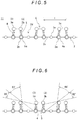
- the color of the warp-knitted fabric 1 visually recognized by an observer who looks at the warp-knitted fabric 1 from a direction intersecting the knitting direction is changed in accordance with the position of the observer. Specifically, when the observer looks at the warp-knitted fabric 1 from the inside of the region R1 that is located on the left side of the sheet in Fig. 3 , the top portion 3 as well as the side wall portion 4 are visually recognized by the observer; therefore, the observer can visually recognize the first and second colors. Meanwhile, the side wall portion 5 is located in the observer's blind spot; therefore, the third color is not visually recognized by the observer.
- the observer looks at the warp-knitted fabric 1 from the inside of the region R2 that is located on the right side of the sheet in Fig. 3 , the top portion 3 as well as the side wall portion 5 are visually recognized by the observer; therefore, the observer can visually recognize the first and third colors. Meanwhile, the side wall portion 4 is located in the observer's blind spot; therefore, the second color is not visually recognized by the observer.
- the angles of the region R1 and region R2 are approximately 40° to 60°.
- the region 3 and the region 4 in Fig. 3 accompany the region R1 and the region R2, respectively.
- the region R3 and the region R4 complement a duration in which the position of the observer changes from the inside of the region R1 to the inside of the region R2, that is, transition from the state where the observer visually recognizes the first and second colors to the state where the observer mainly visually recognizes the first and third colors, thereby effectively serving to produce an elegant color effect.
- the warp-knitted fabric 1 produces a color effect such that the color of the warp-knitted fabric 1 visually recognized by an observer who looks at the warp-knitted fabric 1 is changed in accordance with the position of the observer.
- this warp-knitted fabric 1 is used for clothes, a bag, shoes, or the like, the color effect is exhibited by a change of the position of the observer relative to the surface of the warp-knitted fabric 1 caused by a motion of the wearer; which allows the clothes or the like to have an excellent beautiful appearance or liveness.
- the coupling yarn 2c uses a transparent knitting yarn, the colors of the ridge portions 6 are more conspicuous than in a case where the coupling yarn 2c uses a colored yarn.
- the ridge portions 6 are much less likely to be non-uniform in shape as described above, the color effect is stably exhibited as compared with the conventional knitted fabrics. Further, because the ridge portions 6 have high shape stability, the color effect is stably exhibited even when the warp-knitted fabric 1 is used for clothes or the like and an external force is applied thereto due to a motion of the wearer.
- a warp-knitted fabric 11 according to a second embodiment of the present invention is described with reference to Figs. 4 and 5 .
- Fig. 4 omits illustration of the chain-stitch rows 2a, 2b of the base 2
- Fig. 5 illustrates a total of three ridge portions by illustrating a ridge portion which is not illustrated in Fig. 4 .
- the same components as those of the warp-knitted fabric 1 are denoted by the same reference signs and detailed description thereof is omitted.
- the warp-knitted fabric 11 is knitted such that the coupling portion 2d of the base 2 has a chain-stitch row 2e as a part of the base 2 knitted therein which is knitted with a knitting yarn different from the coupling yarn 2c, and the chain-stitch rows 2a, 2b, 2e including the chain-stitch row 2e are coupled to other chain-stitch rows 2a, 2b 2e located near them by a plurality of coupling yarns 2c in a wale direction. Note that it does not matter whether the knitting yarn used for the chain-stitch row 2e is colored or colorless; however, using a transparent knitting yarn can easily accentuate the colors of the ridge portion 6.
- the space between the ridge portions 6 is wider than that of the warp-knitted fabric 1. Therefore, as shown in Fig. 6 , the region R1' from which the top portion 3 and the side wall portion 4 are visually recognized and the region R2' from which the top portion 3 and the side wall portion 5 are visually recognized are smaller than the region R1 and the region R2 for the warp-knitted fabric 1, respectively. Meanwhile, the region R3' and the region R4' are larger than the region R3 and the region R4, respectively.
- the warp-knitted fabric 11 exhibits a more brilliant color change.
- the number of chain-stitch rows 2e knitted in the coupling portion 2d is not necessarily limited to one and may be two or more. However, making the space between the ridge portions 6 excessively wide could make the region R1' and the region R2' too small to sufficiently exhibit the color effect, or could cause the base 2 to be exposed so much that the beauty of the knitted fabric 11 is impaired.
- the number of chain-stitch rows 2e is determined taking the height h of the ridge portions 6 into account so that the ranges of the region R1' and region R2' are an appropriate value (preferably, approximately not smaller than 20°), the ranges of the region R3' and region R4' are an appropriate value (preferably, approximately not smaller than 40°), and the space I between the ridge portions 6 is approximately 1.5 mm to 4 mm (which is equivalent to approximately 3 to 5 knitting needles).
- a warp-knitted fabric 21 according to third embodiment of the present invention is described below with reference to Fig. 7 .
- the same components as those of the warp-knitted fabric 1 are denoted by the same reference signs and detailed description thereof is omitted.
- Fig. 7 also omits illustration of the chain-stitch rows 2a, 2b of the base 2.
- the warp-knitted fabric 21 is knitted such that the coupling portion 2d of the base 2 has a chain-stitch row 2e knitted therein, and parts of the chain-stitch rows 2a, 2b, 2e including the chain-stitch row 2e are coupled to parts of other chain-stitch rows 2a, 2b, 2e located near them by a plurality of coupling yarns 2c in a wale direction so that the coupling portion 2d of the base 2 is formed in a so-called mesh pattern.
- the chain-stitch row 2e is indicated by solid lines.
- this warp-knitted fabric 21 produces a color effect such that the color of the warp-knitted fabric is changed in accordance with the position of the observer who looks at the warp-knitted fabric 21. Further, forming the coupling portion 2d of the base 2 in a mesh pattern enables reduction of the weight of the warp-knitted fabric 21 itself and, when it is used for clothes or the like, the clothes or the like can have high air permeability.
- a warp-knitted fabric 31 according to a fourth embodiment is described below with reference to Fig. 8 .
- the same components as those of the warp-knitted fabric 1 are denoted by the same reference signs and detailed description thereof is omitted.
- the coupling portion 2d of the base 2 has a stitch row 2f formed therein which is composed of loops and if formed by the coupling yarn 2c, and the coupling yarn 2c is connected to the chain-stitch rows 4a, 5a of the side wall portions 4, 5, whereby the coupling portion 2d of the base 2 is formed in a mesh pattern.
- this warp-knitted fabric 31 also produces a color effect such that the color of the knitted fabric 31 is changed in accordance with the position of the observer who looks at the warp-knitted fabric 31. Further, forming the coupling portion 2d in a mesh pattern enables reduction of the weight of the knitted fabric itself and, when it is used for clothes or the like, the clothes or the like can have high air permeability.
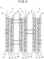
- a warp-knitted fabric 41 according to a fifth embodiment is described below with reference to Fig. 9 .
- the same components as those of the warp-knitted fabric 1 are denoted by the same reference signs and detailed description thereof is omitted.
- illustration of the base 2 is entirely omitted.
- this warp-knitted fabric 41 is knitted such that a part of the top portion 3 of each ridge portion 6 is coupled to parts of the top portions 3 of other ridge portions 6 adjacent thereto by a plurality of coupling yarns 7 so that a mesh-patterned structure is formed in a plane lying almost at the same height as the top portions 3.
- the coupling yarns 7 are colored yarns.
- the coupling yarns 7 are indicated by dotted lines.
- this warp-knitted fabric 41 may have a knitted structure having cuts (small openings) formed therein which is formed in a plane lying almost at the same height as the top portions 3 by knitting a wide knitted area with the plurality of knitting yarns 7 that couple the top portions 3 to each other.
- Fig. 10 illustrates a thus-knitted warp-knitted fabric 51 which is seen from the surface side.
- the reference sign 52 indicates the wide knitted area and the reference sign 53 indicate the cut.
- the warp-knitted fabric 51 As shown in Fig. 10 , on this warp-knitted fabric 51, the wide knitted area 52 knitted with the plurality of coupling yarns 7 is visually recognized by the observer and the top portions 3 and side wall portions 4, 5 of the ridge portions 6 are visually recognized through the cuts 53. Therefore, the warp-knitted fabric 51 has a beautiful appearance different from those of warp-knitted fabrics having no wide knitted area 52 knitted therein, and a complicated pattern appears on the surface of the warp-knitted fabric 51.
- the appearance of the warp-knitted fabric 51 is changed by changing the color of the coupling yarns 7 or combination of the colors of the knitting yarn for the chain-stitch rows 3a, 3b of the top portion 3 and knitting yarns for the chain-stitch rows 4a, 5a of the side wall portions 4, 5. Therefore, when the warp-knitted fabric 51 is used for clothes or shoes, it is easy to allow the clothes or shoes to have diversity in appearance.
- the chain-stitch rows 3a, 3b constituting the top portion 3 are knitted with a knitting yarn of a first color
- the chain-stitch row 4a constituting one side wall portion 4 is knitted with a knitting yarn of a second color
- the chain-stitch row 5a constituting the other side wall portion 5 is knitted with a knitting yarn of a third color, whereby different colors are arranged on the top portion 3 and the side wall portions 4, 5.
- the present invention is not limited thereto and it is enough if any one of the top portion 3 and side wall portions 4, 5 is of a different color from the others of them.
- the chain-stitch rows 3a, 3b, 4a constituting the top portion 3 and the side wall portion 4 may be knitted with a knitting yarn of a first color, with the chain-stitch row 5a constituting the side wall portion 5 being knitted with a knitting yarn of a second color.
- the observer visually recognizes only the first color when looking at the warp-knitted fabric from the side wall portion 4 side, whereas the observer visually recognizes the first and second colors when looking at the warp-knitted fabric from the side wall portion 5 side.
- the chain-stitch rows 3a, 3b of the top portion 3 may be knitted with a knitting yarn of a first color, with the chain-stitch rows 4a, 5a of the side wall portions 4, 5 being knitted with a knitting yarn of a second color.
- the observer visually recognizes the first and second colors when looking at the warp-knitted fabric from the side wall portion 4 side or the side wall portion 5 side, whereas the observer visually recognizes almost only the first color when looking at the warp-knitted fabric from the front side.
- any one of the top portion 3 and side wall portions 4, 5 is of a different color from the others of them, it is possible to allow the knitted fabric to exhibit the color effect such that the color of the knitted fabric is changed in accordance with the position of the observer who looks at the knitted fabric from a direction intersecting the knitting direction.
- the top portion 3 is knitted by coupling the two chain-stitch rows 3a, 3b to each other with the coupling yarn 3c.
- the number of chain-stitch rows constituting the top portion 3 is not limited thereto and the top portion 3 may be knitted by coupling three or more chain-stitch rows to each other with a coupling yarn.
- the coupling yarn 2c uses a transparent yarn.
- the present invention is not limited thereto and the coupling yarn may use a colored yarn.
Landscapes
- Engineering & Computer Science (AREA)
- Textile Engineering (AREA)
- Knitting Of Fabric (AREA)
Abstract
Description
- The present invention relates to a knitted fabric having ridge portions formed thereon along a knitting direction and a method of knitting such a fabric. More particularly, the present invention relates to a knitted fabric knitted so that the color of the knitted fabric which is visually recognized by an observer who looks at the knitted fabric from a direction intersecting the knitting direction is changed in accordance with the position of the observer, and a method of knitting such a fabric.
- In recent years, more and more consumers desire more high-fashion clothes, bags, and shoes and, in order to meet such consumers' desires, a knitted fabric to allow clothes or the like to have an excellent, beautiful appearance or liveness has been actively developed. Typically, such a knitted fabric is provided with a color effect which is produced by a method such as using a plurality of yarns having different colors or made of different materials, combining structures, or using a mesh design or the like, and clothes or the like using such a knitted fabric exhibit an excellent, beautiful appearance or liveness caused by the color effect provided on the knitted fabric.
- As for such a knitted fabric provided with a color effect, for example, a knitted fabric provided with a color effect called "iridescence" (Japanese Unexamined Patent Application Publication No.
2003-41465 2013-124419 - The conventional knitted fabric disclosed in Japanese Unexamined Patent Application Publication No.
2003-41465 - The conventional knitted or woven fabric disclosed in Japanese Unexamined Patent Application Publication No.
2013-124419 - As described above, both of the above-described conventional arts provide a knitted fabric with a color effect. Therefore, clothes or the like using such a knitted fabric can exhibit an extraordinary, beautiful appearance or liveness because the knitted fabric looks different when the position of the observer relative to the knitted fabric is changed by a motion of the wearer.
-
- Patent Literature 1: Japanese Unexamined Patent Application Publication No.
2003-41465 - Patent Literature 2: Japanese Unexamined Patent Application Publication No.
2013-124419 - By the way, in order to obtain a color effect, the above-described conventional knitted fabric requires performing at least two dyeing steps after the fabric is knitted. Therefore, the production process for the knitted fabric is complex and takes much time, which increases the production cost. Further, the knitting yarns to be used for the knitted fabric have to be able to be dyed in different colors; therefore, there is a problem that the knitting yarns are limited in kind.
- Further, performing different dyeing steps necessarily increases the amount of dye liquids to be used therefor; therefore, the disposal of waste liquids is costly. Further, there is also a problem that a heavy burden is imposed on the environment.
- On the other hand, the above-described conventional knitted or woven fabric has the ridges that are the double-layer hollow structure portions in the upper fabric raised by heat shrinkage of the double-layer hollow structure portions in the lower fabric. These ridges cannot be freely controlled in shape, and therefore the ridges are non-uniform in shape. Accordingly, for example, if the top portions of the ridges are different in position, on some ridges, right and left surfaces thereof have different colors arranged thereon, whereas on other ridges, a color supposed to be arranged only on one surface thereof is arranged on a part of the other surface thereof. Therefore, there is a problem that, when the fabric is looked at from the other surface side, it lacks uniformity because the color supposed to be arranged on the one surface is visually recognized on a part of the other surface, and it is therefore difficult to obtain a sufficient color effect.
- Further, the ridges merely result from parts of the upper fabric being raised; therefore, it cannot be said that the ridges per se have high shape stability. Therefore, the ridges are easily transformed in shape when an external force is applied thereto. Accordingly, if this knitted or woven fabric is used for clothes or the like, there is a problem that the ridges are transformed in shape when an external force is applied thereto by a motion of the wearer, and therefore the clothes or the like have trouble exhibiting an expected color effect.
- As described above, the conventional knitted or woven fabric has the problem that it is difficult to exhibit a color effect; therefore, even if it is used for clothes or the like, the clothes or the like are not necessarily provided with a sufficient beauty or liveness.
- The present invention has been achieved in view of the above-described circumstances, and an object thereof is to provide a kitted fabric which does not particularly require knitting yarns to be used therefor to be limited in kind, can be produced at low cost, and can exhibit a stable color effect, and a method of knitting such a fabric.
- The present invention, for solving the above-described problems, relates to a knitted fabric having a base and a plurality of ridge portions formed in parallel to each other along a knitting direction on the base,
the ridge portions each including a top portion and two side wall portions, the top portion being formed by a stitch row extending along the knitting direction, the two side wall portions each being formed by a stitch row extending in the knitting direction and knitted such that it is knitted in the base at the base side thereof and engaged with the top portion at the top portion side thereof to couple the top portion to the base,
at least one of the top and two side wall portions having a different color arranged thereon from the others of the top portion and two side wall portions. - On the above knitted fabric, because at least one of the top portion and two side wall portions constituting each ridge portion has a different color arranged thereon from the others of them, a color effect such that the color of the knitted fabric which is visually recognized by an observer who looks at the knitted fabric from a direction intersecting the knitting direction is changed in accordance with the position of the observer is exhibited.
- For example, in a case the top portion has arranged thereon a color different from a color arranged on the two side wall portions, when the surface of the knitted fabric is looked at from the front side, the color arranged on the top portion is visually recognized, whereas when the knitted fabric is looked at from the direction intersecting the knitting direction, the color arranged on the top portion as well as the color arranged on the two side wall portions are visually recognized.
- Further, in a case where the top portion and one of the side wall portions have arranged thereon a color different from a color arranged on the other of the side wall portions, when the knitted fabric is looked at from the one side wall portion side, the color arranged on the top portion and the one side wall portion is visually recognized, whereas when the knitted fabric is looked at from the other side wall portion side, the color arranged on the other side wall portion is visually recognized.
- Furthermore, in a case where the top portion and the two side wall portions have different colors arranged thereon from one another, when the surface of the knitted fabric is looked at from the front side, the color arranged on the top portion is visually recognized. When the knitted fabric is looked at from one side wall portion side, the color arranged on the top portion as well as the color arranged on the one side wall portion are visually recognized, whereas when the knitted fabric is looked at from the other side wall portion side, the color arranged on the top portion as well as the color arranged on the other side wall portion are visually recognized.
- Thus, this knitted fabric exhibits a color effect such that the color of the knitted fabric which is visually recognized by an observer who looks at the knitted fabric is changed in accordance with the position of the observer.
- Further, in the knitted fabric according to the present invention, because the side wall portions are knitted in the base and engaged with the top portion, the ridge portion per se has high shape stability and it is less likely to be transformed in shape even when an external force is applied thereto. Therefore, the degree of the color effect of the knitted fabric is less likely to be influenced by the manner of use, and therefore the color effect can be sufficiently exhibited.
- Note that, in the above knitted fabric, it is preferred that the top portion is formed by at least two chain-stitch rows coupled to each other by a coupling yarn, each of the two side wall portions is formed by a chain-stitch row, and the chain-stitch rows of the side wall portions are engaged with the top portion in a state where loops formed on the top portion sides thereof are inserted in the chain-stitch rows of the top portion.
- In this case, the knitted fabric can be preferably knitted by a fabric knitting method which uses a knitting machine to knit a knitted fabric having a base and a plurality of ridge portions formed in parallel to each other along a knitting direction on the base, the ridge portions each including a top portion and two side wall portions coupling the top portion to the base, the knitting machine including at least one pair of needle beds having a plurality of knitting needles and facing each other, and a feed mechanism feeding a knitting yarn to the knitting needles, the method including:
- while causing the feed mechanism to feed at least one of knitting needles corresponding to the top portion and the two side wall portions with a knitting yarn of a color different from a color of a knitting yarn to be fed to the others of the knitting needles;
- on one of the pair of needle beds, knitting at least two chain-stitch rows and coupling the chain-stitch rows to each other with a coupling yarn to form the top portion; and
- on the other of the pair of needle beds, knitting chain-stitch rows such that loops inserted in the chain-stitch rows constituting the top portion are formed on sides thereof facing the one of the pair of needle beds to form the two side wall portions coupled to the top portion, and forming the base coupled to the two side wall portions.
- With this knitting method, the base and the ridge portions can be formed by knitting chain-stitch rows at the time of knitting. Therefore, as compared with a case where ridges are formed by performing a certain process after knitting as in the conventional method, the ridge portions are less likely to be non-uniform in shape, and therefore the problem that the color effect is not sufficiently exhibited due to nonuniformity in shape of the ridge portions can be solved. Further, this method does not require a dyeing step after knitting, and therefore an increase in cost can be suppressed.
- Note that, as long as at least one of the top portion and two side wall portions is able to have a different color from the others of them as mentioned above, the knitting yarns to be used therefor are not particularly limited in kind and can be freely selected for use from filament yarns and spun yarns.
- Further, in the above knitted fabric, the coupling yarn may be extended between a part of the top portion of each ridge portion and parts of the top portions of other ridge portions adjacent thereto to form a mesh portion. In this case, because each ridge portion is coupled to other ridge portions adjacent thereto by the mesh portion, the ridge portions can have more improved shape stability. Further, the mesh portion being formed causes the ridge portions to be visually recognized through openings of the mesh portion; therefore, as compared with the case where no mesh portion is formed, it is possible to express a complicated pattern.
- Furthermore, the above knitted fabric may have formed thereon a knitted area having at least one cut (opening), the knitted area being knitted to couple a part of the top portion of each ridge portion to parts of the top portions of other ridge portions adjacent thereto. Also in this case, similarly to the above case, because the ridge portions are coupled to each other by the knitted area, the ridge portions can have improved shape stability and the color effect can be stably exhibited. Further, because the ridge portions are visually recognized through the cut, as compared with the case where no knitted area is formed, the knitted fabric can show a complicated pattern on the surface thereof.
- Further, the base may have at least one stitch row formed therein between each ridge portion and other ridge portions adjacent thereto. In this case, each ridge portion is spaced apart from the ridge portions adjacent thereto, and therefore the space between the ridge portions is made wider. Therefore, the ranges of the position of the observer which allow the side wall portions to be visually recognized are changed, which allows the color effect to be exhibited differently from the case where the space between the ridge portions is narrow. Note that making the space between the ridge portions excessively wide could make the ranges of the position of the observer which allow the side wall portions to be visually recognized too small to sufficiently exhibit the color effect, or could cause the base to be visually recognized so much that the beautiful appearance of the knitted fabric is impaired. Accordingly, it is preferred that the number of stitch rows to be formed is adjusted so that the space between the ridge portions is approximately 1.5 mm to 4 mm (which is equivalent to approximately 3 to 5 knitting needles).
- Note that the base may be formed in a mesh pattern and may use a transparent yarn for the knitting yarn therefor. Forming the base in a mesh pattern enables reduction of the weight of the knitted fabric and, when such a knitted fabric is used for clothes or the like, the clothes or the like can have high air permeability. Further, using a transparent yarn for the knitting yarn for the base makes the base inconspicuous and accentuates the colors of the ridge portions, which enhances the color effect produced by arranging different colors on the top portion and two side wall portions constituting the ridge portion.
- As described above, the knitted fabric according to the present invention does not particularly require the knitting yarns to be used therefor to be limited in kind, reduces production costs, and nevertheless can stably exhibit an enhanced color effect. When this knitted fabric is used for clothes or the like, the knitted fabric can provide the clothes or the like with an extremely excellent, beautiful appearance or liveness.
- Further, with the fabric knitting method according to the present invention, it is possible to make the ridge portions less likely to be non-uniform in shape; therefore, it is possible to knit a fabric which sufficiently exhibits a color effect.
-
-
Fig. 1 shows details of a structure of a warp-knitted fabric according to a first embodiment; -
Fig. 2 is a sectional view taken along the line A-A inFig. 1 ; -
Fig. 3 is an illustration for explaining a color effect of the warp-knitted fabric according to the first embodiment; -
Fig. 4 shows details of a structure of a warp-knitted fabric according to a second embodiment; -
Fig. 5 is a sectional view taken along the line B-B inFig. 4 ; -
Fig. 6 is an illustration for explaining a color effect of the warp-knitted fabric according to the second embodiment; -
Fig. 7 shows details of a structure of a warp-knitted fabric according to a third embodiment; -
Fig. 8 shows details of a structure of a warp-knitted fabric according to a fourth embodiment; -
Fig. 9 shows details of a structure of a warp-knitted fabric according to a fifth embodiment; and -
Fig. 10 shows a variation of the warp-knitted fabric according to the fifth embodiment. - Hereinafter, specific embodiments of the present invention will be described with reference to the drawings.
-
Fig. 1 shows details of a structure of a warp-knittedfabric 1 according to a first embodiment, andFig. 2 is a sectional view taken along the line A-A inFig. 1 . As shown inFigs. 1 and 2 , the warp-knittedfabric 1 consists of abase 2 andridge portions 6 formed along a knitting direction, eachridge portion 6 being composed of atop portion 3 and twoside wall portions top portion 3. - The
top portion 3 is formed by two chain-stitch rows coupling yarn 3c, and theside wall portions stitch rows 5a having loops stitch rows base 2 is composed of chain-stitch rows coupling portions 2d formed between theridge portions 6, the chain-stitch rows stitch rows side wall portions coupling portion 2d being formed by acoupling yarn 2c coupling the chain-stitch rows Fig. 1 , the chain-stitch rows top portion 3 and thechain stitch rows side wall portions coupling yarn 3c of thetop portion 3 is indicated by broken lines, thecoupling yarn 2c of thebase 2 is indicated by dotted lines, and illustration of the chain-stitch rows base 2 is omitted. - Further, in the warp-knitted
fabric 1 according to this embodiment, a knitting yarn of a first color is used for the two chain-stitch rows top portion 3, a knitting yarn of a second color is used for the chain-stitch row 4a constituting theside wall portion 4, a knitting yarn of a third color is used for the chain-stitch row 5a constituting theside wall portion 5, and a transparent knitting yarn is used for the chain-stitch rows base 2 and thecoupling yarns stitch rows base 2 may respectively use colored yarns of the same colors as those of the chain-stitch rows side wall portions coupling yarn 3c of thetop portion 3 may use a colored yarn of the same color as that of the chain-stitch rows top portion 3. - Note that examples of the knitting yarns used for the chain-
stitch rows base 2, chain-stitch rows coupling yarns 3c of thetop portions 3, and chain-stitch rows side wall portions coupling yarn 2c of thebase 2 include mono-filament yarns with high transparency made of polyester, thermoplastic elastomer, nylon, or the like. - This warp-knitted
fabric 1 can be knitted by using a well-known double raschel knitting machine including two needle beds having a plurality of knitting needles and oppositely arranged, and a feed mechanism feeding predetermined yarns to the needle beds. - Specifically, on one of the needle beds (front-side needle bed), the
top portion 3 is formed by knitting the two chain-stitch rows stitch rows coupling yarn 3c. - On the other hand, on the other of the needle beds (rear-side needle bed), the two chain-
stitch rows side wall portions stitch rows base 2 are knitted with a transparent knitting yarn that is fed by the feed mechanism, and simultaneously the chain-stitch rows stitch rows coupling yarns 2c, along the wale direction. - In the knitted fabric according to this embodiment, when the chain-
stitch rows side wall portions loops stitch rows loops stitch rows top portion 3, whereby the chain-stitch rows side wall portions stitch rows top portion 3. Meanwhile, the chain-stitch rows side wall portions stitch rows base 2, whereby the chain-stitch rows side wall portions stitch rows base 2, respectively. - Thus, the
top portion 3 is coupled to thebase 2 by theside wall portions ridge portions 6 each composed of thetop portion 3 and theside wall portions base 2. - In the thus-knitted wrap-knitted
fabric 1, because thebase 2 and theridge portions 6 are formed at the time of knitting, theridge portions 6 are less likely to be non-uniform in shape and theridge portions 6 are therefore almost uniform in shape. Further, eachridge portion 6 is composed of thetop portion 3 and theside wall portions stitch rows side wall portions stitch rows top portion 3 and knitted in the chain-stitch rows base 2. Therefore, theridge portions 6 have higher shape stability than the conventional ones. - Note that the height h from the
base 2 to thetop portion 3 depends on the distance between the oppositely arranged two needle beds in the double raschel knitting machine and the elasticities of the knitting yarns. However, when the height h is higher, the shape of theridge portions 6 is more breakable. Therefore, it is preferred that the distance between the needle beds is changed or a tension or the like during knitting is adjusted so that the height h is approximately 1 mm to 4 mm. - Next, a color effect produced by the warp-knitted
fabric 1 is described below with reference toFig. 3 . - The color of the warp-knitted
fabric 1 visually recognized by an observer who looks at the warp-knittedfabric 1 from a direction intersecting the knitting direction is changed in accordance with the position of the observer. Specifically, when the observer looks at the warp-knittedfabric 1 from the inside of the region R1 that is located on the left side of the sheet inFig. 3 , thetop portion 3 as well as theside wall portion 4 are visually recognized by the observer; therefore, the observer can visually recognize the first and second colors. Meanwhile, theside wall portion 5 is located in the observer's blind spot; therefore, the third color is not visually recognized by the observer. - In contrast, when the observer looks at the warp-knitted
fabric 1 from the inside of the region R2 that is located on the right side of the sheet inFig. 3 , thetop portion 3 as well as theside wall portion 5 are visually recognized by the observer; therefore, the observer can visually recognize the first and third colors. Meanwhile, theside wall portion 4 is located in the observer's blind spot; therefore, the second color is not visually recognized by the observer. Note that, in this embodiment, the angles of the region R1 and region R2 are approximately 40° to 60°. - The
region 3 and theregion 4 inFig. 3 accompany the region R1 and the region R2, respectively. For example, the region R3 and the region R4 complement a duration in which the position of the observer changes from the inside of the region R1 to the inside of the region R2, that is, transition from the state where the observer visually recognizes the first and second colors to the state where the observer mainly visually recognizes the first and third colors, thereby effectively serving to produce an elegant color effect. - As described above, the warp-knitted
fabric 1 according to this embodiment produces a color effect such that the color of the warp-knittedfabric 1 visually recognized by an observer who looks at the warp-knittedfabric 1 is changed in accordance with the position of the observer. When this warp-knittedfabric 1 is used for clothes, a bag, shoes, or the like, the color effect is exhibited by a change of the position of the observer relative to the surface of the warp-knittedfabric 1 caused by a motion of the wearer; which allows the clothes or the like to have an excellent beautiful appearance or liveness. Note that, because thecoupling yarn 2c uses a transparent knitting yarn, the colors of theridge portions 6 are more conspicuous than in a case where thecoupling yarn 2c uses a colored yarn. - Further, on the warp-knitted
fabric 1, because theridge portions 6 are much less likely to be non-uniform in shape as described above, the color effect is stably exhibited as compared with the conventional knitted fabrics. Further, because theridge portions 6 have high shape stability, the color effect is stably exhibited even when the warp-knittedfabric 1 is used for clothes or the like and an external force is applied thereto due to a motion of the wearer. - Next, a warp-knitted
fabric 11 according to a second embodiment of the present invention is described with reference toFigs. 4 and5 . Note thatFig. 4 omits illustration of the chain-stitch rows base 2, andFig. 5 illustrates a total of three ridge portions by illustrating a ridge portion which is not illustrated inFig. 4 . Further, in the following description, the same components as those of the warp-knittedfabric 1 are denoted by the same reference signs and detailed description thereof is omitted. - As shown in
Figs. 4 and5 , the warp-knittedfabric 11 is knitted such that thecoupling portion 2d of thebase 2 has a chain-stitch row 2e as a part of thebase 2 knitted therein which is knitted with a knitting yarn different from thecoupling yarn 2c, and the chain-stitch rows stitch row 2e are coupled to other chain-stitch rows 2b 2e located near them by a plurality ofcoupling yarns 2c in a wale direction. Note that it does not matter whether the knitting yarn used for the chain-stitch row 2e is colored or colorless; however, using a transparent knitting yarn can easily accentuate the colors of theridge portion 6. - In this warp-knitted
fabric 11, because the chain-stitch row 2e is additionally knitted in thecoupling portion 2d of thebase 2, the space between theridge portions 6 is wider than that of the warp-knittedfabric 1. Therefore, as shown inFig. 6 , the region R1' from which thetop portion 3 and theside wall portion 4 are visually recognized and the region R2' from which thetop portion 3 and theside wall portion 5 are visually recognized are smaller than the region R1 and the region R2 for the warp-knittedfabric 1, respectively. Meanwhile, the region R3' and the region R4' are larger than the region R3 and the region R4, respectively. - Accordingly, because the region R3' and the region R4' are larger, the warp-knitted
fabric 11 exhibits a more brilliant color change. - Note that the number of chain-
stitch rows 2e knitted in thecoupling portion 2d is not necessarily limited to one and may be two or more. However, making the space between theridge portions 6 excessively wide could make the region R1' and the region R2' too small to sufficiently exhibit the color effect, or could cause thebase 2 to be exposed so much that the beauty of the knittedfabric 11 is impaired. Therefore, it is preferred that the number of chain-stitch rows 2e is determined taking the height h of theridge portions 6 into account so that the ranges of the region R1' and region R2' are an appropriate value (preferably, approximately not smaller than 20°), the ranges of the region R3' and region R4' are an appropriate value (preferably, approximately not smaller than 40°), and the space I between theridge portions 6 is approximately 1.5 mm to 4 mm (which is equivalent to approximately 3 to 5 knitting needles). - Next, a warp-knitted
fabric 21 according to third embodiment of the present invention is described below with reference toFig. 7 . Note that, similarly to the above description, the same components as those of the warp-knittedfabric 1 are denoted by the same reference signs and detailed description thereof is omitted. Further,Fig. 7 also omits illustration of the chain-stitch rows base 2. - As shown in
Fig. 7 , the warp-knittedfabric 21 according to the third embodiment is knitted such that thecoupling portion 2d of thebase 2 has a chain-stitch row 2e knitted therein, and parts of the chain-stitch rows stitch row 2e are coupled to parts of other chain-stitch rows coupling yarns 2c in a wale direction so that thecoupling portion 2d of thebase 2 is formed in a so-called mesh pattern. Note that, inFig. 7 , the chain-stitch row 2e is indicated by solid lines. - Similarly to the warp-knitted
fabric 1, this warp-knittedfabric 21 produces a color effect such that the color of the warp-knitted fabric is changed in accordance with the position of the observer who looks at the warp-knittedfabric 21. Further, forming thecoupling portion 2d of thebase 2 in a mesh pattern enables reduction of the weight of the warp-knittedfabric 21 itself and, when it is used for clothes or the like, the clothes or the like can have high air permeability. - Next, a warp-knitted
fabric 31 according to a fourth embodiment is described below with reference toFig. 8 . Note that, in the following description, similarly to the above descriptions, the same components as those of the warp-knittedfabric 1 are denoted by the same reference signs and detailed description thereof is omitted. - As shown in
Fig. 8 , differently from the warp-knittedfabrics fabric 31, thecoupling portion 2d of thebase 2 has astitch row 2f formed therein which is composed of loops and if formed by thecoupling yarn 2c, and thecoupling yarn 2c is connected to the chain-stitch rows side wall portions coupling portion 2d of thebase 2 is formed in a mesh pattern. - Similarly to the warp-knitted
fabric 21, this warp-knittedfabric 31 also produces a color effect such that the color of the knittedfabric 31 is changed in accordance with the position of the observer who looks at the warp-knittedfabric 31. Further, forming thecoupling portion 2d in a mesh pattern enables reduction of the weight of the knitted fabric itself and, when it is used for clothes or the like, the clothes or the like can have high air permeability. - Next, a warp-knitted
fabric 41 according to a fifth embodiment is described below with reference toFig. 9 . Note that, similarly to the above descriptions, the same components as those of the warp-knittedfabric 1 are denoted by the same reference signs and detailed description thereof is omitted. Further, inFig. 9 , illustration of thebase 2 is entirely omitted. - As shown in
Fig. 9 , this warp-knittedfabric 41 is knitted such that a part of thetop portion 3 of eachridge portion 6 is coupled to parts of thetop portions 3 ofother ridge portions 6 adjacent thereto by a plurality ofcoupling yarns 7 so that a mesh-patterned structure is formed in a plane lying almost at the same height as thetop portions 3. Note that it is preferred that thecoupling yarns 7 are colored yarns. Further, inFig. 9 , thecoupling yarns 7 are indicated by dotted lines. - In this warp-knitted
fabric 41, because the mesh-patterned structure is formed in a plane lying almost at the same height as thetop portions 3, theridge portions 6 are visually recognized through openings of the mesh pattern by the observer. Therefore, as compared with the case where no mesh-patterned structure is formed, it is possible to express a complicated pattern. Further, because eachridge portion 6 is coupled toother ridge portions 6, theridge portions 6 can have improved shape stability. - Note that this warp-knitted
fabric 41 may have a knitted structure having cuts (small openings) formed therein which is formed in a plane lying almost at the same height as thetop portions 3 by knitting a wide knitted area with the plurality ofknitting yarns 7 that couple thetop portions 3 to each other.Fig. 10 illustrates a thus-knitted warp-knittedfabric 51 which is seen from the surface side. InFig. 10 , thereference sign 52 indicates the wide knitted area and thereference sign 53 indicate the cut. - As shown in
Fig. 10 , on this warp-knittedfabric 51, the wide knittedarea 52 knitted with the plurality ofcoupling yarns 7 is visually recognized by the observer and thetop portions 3 andside wall portions ridge portions 6 are visually recognized through thecuts 53. Therefore, the warp-knittedfabric 51 has a beautiful appearance different from those of warp-knitted fabrics having no wide knittedarea 52 knitted therein, and a complicated pattern appears on the surface of the warp-knittedfabric 51. Further, the appearance of the warp-knittedfabric 51 is changed by changing the color of thecoupling yarns 7 or combination of the colors of the knitting yarn for the chain-stitch rows top portion 3 and knitting yarns for the chain-stitch rows side wall portions fabric 51 is used for clothes or shoes, it is easy to allow the clothes or shoes to have diversity in appearance. - Hereinbefore, several embodiments of the present invention have been described. However, the present invention is not limited thereto and can be implemented in other modes.
- For example, in the above embodiments, the chain-
stitch rows top portion 3 are knitted with a knitting yarn of a first color, the chain-stitch row 4a constituting oneside wall portion 4 is knitted with a knitting yarn of a second color, and the chain-stitch row 5a constituting the otherside wall portion 5 is knitted with a knitting yarn of a third color, whereby different colors are arranged on thetop portion 3 and theside wall portions top portion 3 andside wall portions - Specifically, the chain-
stitch rows top portion 3 and theside wall portion 4 may be knitted with a knitting yarn of a first color, with the chain-stitch row 5a constituting theside wall portion 5 being knitted with a knitting yarn of a second color. In this case, the observer visually recognizes only the first color when looking at the warp-knitted fabric from theside wall portion 4 side, whereas the observer visually recognizes the first and second colors when looking at the warp-knitted fabric from theside wall portion 5 side. - Further, the chain-
stitch rows top portion 3 may be knitted with a knitting yarn of a first color, with the chain-stitch rows side wall portions side wall portion 4 side or theside wall portion 5 side, whereas the observer visually recognizes almost only the first color when looking at the warp-knitted fabric from the front side. - Thus, when any one of the
top portion 3 andside wall portions - Further, in the above embodiments, the
top portion 3 is knitted by coupling the two chain-stitch rows coupling yarn 3c. However, the number of chain-stitch rows constituting thetop portion 3 is not limited thereto and thetop portion 3 may be knitted by coupling three or more chain-stitch rows to each other with a coupling yarn. - Furthermore, in the above embodiments, the
coupling yarn 2c uses a transparent yarn. However, the present invention is not limited thereto and the coupling yarn may use a colored yarn. -
- 1, 11, 21, 31, 41, 51
- Warp-knitted fabric
- 2
- Base
- 2a, 2b
- Chain-stitch row
- 2c
- Coupling yarn
- 2d
- Coupling portion
- 2e
- Chain-stitch row
- 2f
- Stitch row
- 3
- Top portion
- 3a, 3b
- Chain-stitch row
- 3c
- Coupling yarn
- 4, 5
- Side wall portion
- 4a, 5a
- Chain-stitch row
- 4a1, 5a1
- Loop
- 6
- Ridge portion
- 7
- Coupling yarn
Claims (13)
- A knitted fabric having a base and a plurality of ridge portions formed in parallel to each other along a knitting direction on the base, characterized in that:each of the ridge portions comprises a top portion and two side wall portions, the top portion being formed by a stitch row extending in the knitting direction, each of the two side wall portions being formed by a stitch row extending in the knitting direction and knitted such that it is knitted in the base at the base side thereof and engaged with the top portion at the top portion side thereof to couple the top portion to the base; andat least one of the top portion and two side wall portions has a different color arranged thereon from the others of the top portion and two side wall portions.
- The knitted fabric according to claim 1, characterized in that:the top portion is formed by at least two chain-stitch rows coupled to each other by a coupling yarn;each of the two side wall portions is formed by a chain-stitch row; andthe chain-stitch rows of the side wall portions are engaged with the top portion in a state where loops formed on the top portion sides thereof are inserted in the chain-stitch rows of the top portion.
- The knitted fabric according to claim 1 or 2, characterized in that the coupling yarn is extended between a part of the top portion of each of the ridge portions and parts of the top portions of other ridge portions adjacent thereto to form a mesh portion.
- The knitted fabric according to claim 1 or 2, characterized in that the knitted fabric has formed thereon a knitted area having at least one cut, the knitted area being knitted to couple a part of the top portion of each of the ridge portions to parts of the top portions of other ridge portions adjacent thereto.
- The knitted fabric according to any one of claims 1 to 4, characterized in that the base has at least one stitch row formed therein between each of the ridge portions and other ridge portions adjacent thereto.
- The knitted fabric according to any one of claims 1 to 5, characterized in that the base is formed in a mesh pattern.
- The knitted fabric according to any one of claims 1 to 6, characterized in that the base is made of a transparent yarn.
- A fabric knitting method using a knitting machine to knit a knitted fabric having a base and a plurality of ridge portions formed in parallel to each other along a knitting direction on the base, the ridge portions each comprising a top portion and two side wall portions coupling the top portion to the base, the knitting machine comprising at least one pair of needle beds having a plurality of knitting needles and facing each other, and a feed mechanism feeding a knitting yarn to the knitting needles, the method characterized by comprising:while causing the feed mechanism to feed at least one of knitting needles corresponding to the top portion and the two side wall portions with a knitting yarn of a color different from a color of a knitting yarn to be fed to the others of the knitting needles;on one of the pair of needle beds, knitting at least two chain-stitch rows and coupling the chain-stitch rows to each other with a coupling yarn to form the top portion; andon another one of the pair of needle beds, knitting chain-stitch rows such that loops inserted in the chain-stitch rows constituting the top portion are formed on sides thereof facing the one of the pair of needle beds to form the two side wall portions coupled to the top portion, and forming the base coupled to the two side wall portions.
- The fabric knitting method according to claim 8, characterized by extending the coupling yarn between a part of the top portion of each of the ridge portions and parts of the top portions of other ridge portions adjacent thereto to form a mesh portion.
- The fabric knitting method according to claim 8, characterized by forming a knitted area having at least one cut, the knitted area being knitted to couple a part of the top portion of each of the ridge portions to parts of the top portions of other ridge portions adjacent thereto.
- The fabric knitting method according to any one of claims 8 to 10, characterized by forming at least one stitch row between each of the ridge portions and other ridge portions adjacent thereto in the base.
- The fabric knitting method according to any one of claims 8 to 11, characterized by forming the base in a mesh pattern.
- The fabric knitting method according to any one of claims 8 to 12, characterized by causing the feed mechanism to feed a transparent yarn to knitting needles corresponding to the base.
Applications Claiming Priority (3)
| Application Number | Priority Date | Filing Date | Title |
|---|---|---|---|
| JP2015133530 | 2015-07-02 | ||
| JP2016108624A JP6196352B2 (en) | 2015-07-02 | 2016-05-31 | Knitted fabric and its knitting method |
| PCT/JP2016/069303 WO2017002867A1 (en) | 2015-07-02 | 2016-06-29 | Knitted fabric and method for knitting same |
Publications (3)
| Publication Number | Publication Date |
|---|---|
| EP3318666A1 true EP3318666A1 (en) | 2018-05-09 |
| EP3318666A4 EP3318666A4 (en) | 2019-01-23 |
| EP3318666B1 EP3318666B1 (en) | 2021-12-29 |
Family
ID=57829963
Family Applications (1)
| Application Number | Title | Priority Date | Filing Date |
|---|---|---|---|
| EP16817975.2A Active EP3318666B1 (en) | 2015-07-02 | 2016-06-29 | Knitted fabric and method for knitting same |
Country Status (4)
| Country | Link |
|---|---|
| US (1) | US10597805B2 (en) |
| EP (1) | EP3318666B1 (en) |
| JP (1) | JP6196352B2 (en) |
| CN (1) | CN107709643B (en) |
Families Citing this family (17)
| Publication number | Priority date | Publication date | Assignee | Title |
|---|---|---|---|---|
| US9192204B1 (en) | 2014-09-30 | 2015-11-24 | Nike, Inc. | Article of footwear upper incorporating a textile component with tensile elements |
| US9078488B1 (en) | 2014-09-30 | 2015-07-14 | Nike, Inc. | Article of footwear incorporating a lenticular knit structure |
| US10822728B2 (en) * | 2014-09-30 | 2020-11-03 | Nike, Inc. | Knitted components exhibiting color shifting effects |
| US9375046B2 (en) | 2014-09-30 | 2016-06-28 | Nike, Inc. | Article of footwear incorporating a knitted component with inlaid tensile elements and method of assembly |
| USD845650S1 (en) * | 2016-05-24 | 2019-04-16 | Toray Industries, Inc. | Textile fabric |
| JP2018104841A (en) * | 2016-12-26 | 2018-07-05 | 東レ株式会社 | Fiber structure |
| CN109715872B (en) * | 2017-06-15 | 2020-08-21 | 福建华峰新材料有限公司 | A color-changing fabric for the transmission of graphic and text information |
| CN108385266B (en) * | 2018-04-10 | 2023-11-17 | 信泰(福建)科技有限公司 | A kind of see-through double jacquard jacquard mesh fabric and its production method |
| CN112368435A (en) * | 2018-08-10 | 2021-02-12 | 株式会社黑田蕾丝 | Lace knitted fabric |
| CN109667052B (en) * | 2019-02-13 | 2024-05-10 | 信泰(福建)科技有限公司 | A deformation-changing color-changing fabric and its manufacturing process |
| US11566353B2 (en) * | 2019-04-05 | 2023-01-31 | Nike, Inc. | Knit component with differing visual effects |
| US12209337B2 (en) * | 2019-11-07 | 2025-01-28 | Adidas Ag | Knitted garments having colored regions and textured elements and methods of forming the same |
| CN111455548B (en) * | 2020-04-17 | 2022-03-11 | 福建华峰新材料有限公司 | A kind of warp knitted jacquard single-layer mesh cloth and production method |
| CN111733515B (en) * | 2020-06-09 | 2025-08-26 | 信泰(福建)科技有限公司 | A mesh-type jacquard creel double jacquard mesh and a manufacturing method thereof |
| US20240263369A1 (en) * | 2021-06-01 | 2024-08-08 | Asahi Kasei Kabushiki Kaisha | Surface Covering Material |
| MX2023014323A (en) | 2021-06-01 | 2023-12-13 | Asahi Chemical Ind | DOUBLE RASCHEL KNIT FABRIC AND SURFACE COVERING MATERIAL CONTAINING IT. |
| JP7813268B2 (en) * | 2023-10-25 | 2026-02-12 | 林テレンプ株式会社 | Vehicle seat covering material using double knit circular knit fabric, child seat covering material using double knit circular knit fabric, and nursing bed covering material using double knit circular knit fabric |
Family Cites Families (28)
| Publication number | Priority date | Publication date | Assignee | Title |
|---|---|---|---|---|
| JPS6233341A (en) | 1985-08-06 | 1987-02-13 | Canon Inc | Optical information recording and reproducing device |
| JPS61239064A (en) * | 1986-04-01 | 1986-10-24 | 日本マイヤ−株式会社 | Knitting of warp knitted fabric having different loop lengths |
| US5385036A (en) * | 1993-05-24 | 1995-01-31 | Guilford Mills, Inc. | Warp knitted textile spacer fabric, method of producing same, and products produced therefrom |
| WO1995026698A1 (en) * | 1994-03-30 | 1995-10-12 | Smith & Nephew Plc | Medical articles |
| FR2749327B1 (en) * | 1996-06-04 | 1998-06-26 | Commissariat Energie Atomique | KNITTED DOUBLE-SKIN TEXTILE STRUCTURE AND ORIENTABLE BONDING YARN AND METHOD FOR MANUFACTURING THE SAME |
| JP3567702B2 (en) * | 1997-11-13 | 2004-09-22 | 旭土建株式会社 | 3D structural net |
| WO2001044551A1 (en) * | 1999-12-16 | 2001-06-21 | Asahi Doken Kabushiki Kaisha | Three-dimensional maquisette style knitted fabric |
| WO2002050352A1 (en) * | 2000-12-18 | 2002-06-27 | Asahi Doken Kabushiki Kaisha | Double knitted fabric |
| JP3751183B2 (en) * | 2000-03-31 | 2006-03-01 | セーレン株式会社 | 3D warp knitted fabric |
| JP2002138352A (en) * | 2000-10-26 | 2002-05-14 | Suminoe Textile Co Ltd | 3D knitting |
| JP4832663B2 (en) * | 2001-05-16 | 2011-12-07 | 株式会社デルタツーリング | Cushion structure |
| JP2003041465A (en) | 2001-05-25 | 2003-02-13 | Fuasutaa:Kk | Warp knitted fabric with brilliance of iridescent color |
| US7235504B2 (en) * | 2001-09-28 | 2007-06-26 | Seiren Co., Ltd. | Three dimensional knitted fabric having unevenness |
| JP3926187B2 (en) * | 2002-03-29 | 2007-06-06 | セーレン株式会社 | Three-dimensional warp knitted fabric and its knitting method |
| JP4413189B2 (en) * | 2003-03-31 | 2010-02-10 | セーレン株式会社 | Three-dimensional warp knitted fabric that prevents slippage |
| EP1612312A4 (en) * | 2003-03-31 | 2007-02-28 | Seiren Co Ltd | Warp knit fabric with steric structure |
| DE20319433U1 (en) * | 2003-12-14 | 2004-07-01 | Weber, Notger | Absorptive textile three-dimensional textile panel for geriatric and bedridden patients, and shock-absorbing panel for electronic components |
| US7731279B2 (en) * | 2004-04-28 | 2010-06-08 | Massachusetts Institute Of Technology | Rapid cooling and heating of car seats with massaging effects |
| US7076974B1 (en) * | 2005-10-06 | 2006-07-18 | Tsan-Jee Chen | Warp knitting fabric |
| JP4853781B2 (en) * | 2006-09-16 | 2012-01-11 | Tbカワシマ株式会社 | Double knitted fabric |
| JP4849411B2 (en) * | 2007-04-02 | 2012-01-11 | セーレン株式会社 | Saddle-shaped double russell and its manufacturing method |
| US7913520B1 (en) * | 2010-01-20 | 2011-03-29 | Li Cheng Enterprise Co., Ltd | Structure of spacer fabric and thickness-controlled knitting method for producing the same |
| US8448475B2 (en) * | 2010-04-09 | 2013-05-28 | Seiren Co., Ltd. | Skin material for interior material |
| JP5618809B2 (en) | 2010-12-16 | 2014-11-05 | 株式会社島精機製作所 | Knitting method of knitted fabric and knitted fabric |
| JP5764397B2 (en) * | 2011-06-22 | 2015-08-19 | 株式会社Shindo | Moire striped decorative band |
| JP5939782B2 (en) * | 2011-12-13 | 2016-06-22 | 株式会社Shindo | Irregular pattern decorative strip and method for producing the same |
| CN104342842B (en) * | 2014-08-18 | 2015-09-09 | 福建省晋江市华宇织造有限公司 | A kind of far three-layer mesh fabric and production method thereof |
| JP6233341B2 (en) * | 2015-03-27 | 2017-11-22 | Jfeスチール株式会社 | Metal strip draining device and metal strip draining method |
-
2016
- 2016-05-31 JP JP2016108624A patent/JP6196352B2/en active Active
- 2016-06-29 EP EP16817975.2A patent/EP3318666B1/en active Active
- 2016-06-29 CN CN201680039128.6A patent/CN107709643B/en active Active
- 2016-06-29 US US15/735,757 patent/US10597805B2/en active Active
Also Published As
| Publication number | Publication date |
|---|---|
| US20180179676A1 (en) | 2018-06-28 |
| CN107709643B (en) | 2020-06-30 |
| EP3318666A4 (en) | 2019-01-23 |
| CN107709643A (en) | 2018-02-16 |
| JP2017014676A (en) | 2017-01-19 |
| JP6196352B2 (en) | 2017-09-13 |
| US10597805B2 (en) | 2020-03-24 |
| EP3318666B1 (en) | 2021-12-29 |
Similar Documents
| Publication | Publication Date | Title |
|---|---|---|
| EP3318666B1 (en) | Knitted fabric and method for knitting same | |
| JP5342974B2 (en) | Warp knitted fabric, tubular warp knitted fabric and manufacturing method thereof | |
| ES2907693T3 (en) | Knitting and knitting process | |
| CN104164737B (en) | The weaving method of rib-loop style knitted fabric and rib-loop style knitted fabric | |
| CN101663428B (en) | Knitting method for knitted fabric and knitted fabric | |
| IT9021148A1 (en) | SWEATER OR FLEECE KNITWEAR AND CIRCULAR KNITTING MACHINE FOR THEIR MANUFACTURE. | |
| EP3385420B1 (en) | Warp knitting machine, warp knitted fabric manufacturing method and warp knitted fabric | |
| CN103046216A (en) | Knitting method of spacer fabric and spacer fabric | |
| EP3453793A1 (en) | Woven/knitted fabric | |
| JP2013124419A (en) | Decorative narrow belt with uneven pattern and method for manufacturing the same | |
| JPWO2018066463A1 (en) | Warp knitted fabric and its knitting method | |
| JP2001123361A (en) | Patterned three-dimensional fabric by double raschel machine and method for knitting the same fabric | |
| CN102268777A (en) | Knitting method for a knitted fabric having a bifurcation part, and the knitted fabric | |
| CN102534977A (en) | Knitting method of knitted fabric and knitted fabric | |
| JP2014234577A (en) | Warp knitted fabric, and method of manufacturing the same | |
| WO2018123532A1 (en) | Fiber structure | |
| JP5731797B2 (en) | Iridescent color tones | |
| JP3217916U (en) | Decorative fabric | |
| KR101985840B1 (en) | Knitted fabric knitting method and knitted fabric | |
| WO2018123533A1 (en) | Fiber structure | |
| CN216610329U (en) | A high-strength twill knitted fabric | |
| CN215512567U (en) | Three-dimensional color pattern fabric | |
| KR100957451B1 (en) | Irregular two-tone kniting and weaving method thereof | |
| CN121675150A (en) | Mesh-penetrating ground color jacquard gradual-change multilayer knitted fabric and knitting process thereof | |
| JPS584106B2 (en) | How to knit two-sided pile fabric |
Legal Events
| Date | Code | Title | Description |
|---|---|---|---|
| STAA | Information on the status of an ep patent application or granted ep patent |
Free format text: STATUS: THE INTERNATIONAL PUBLICATION HAS BEEN MADE |
|
| PUAI | Public reference made under article 153(3) epc to a published international application that has entered the european phase |
Free format text: ORIGINAL CODE: 0009012 |
|
| STAA | Information on the status of an ep patent application or granted ep patent |
Free format text: STATUS: REQUEST FOR EXAMINATION WAS MADE |
|
| 17P | Request for examination filed |
Effective date: 20180201 |
|
| AK | Designated contracting states |
Kind code of ref document: A1 Designated state(s): AL AT BE BG CH CY CZ DE DK EE ES FI FR GB GR HR HU IE IS IT LI LT LU LV MC MK MT NL NO PL PT RO RS SE SI SK SM TR |
|
| AX | Request for extension of the european patent |
Extension state: BA ME |
|
| DAV | Request for validation of the european patent (deleted) | ||
| DAX | Request for extension of the european patent (deleted) | ||
| REG | Reference to a national code |
Ref country code: DE Ref legal event code: R079 Ref document number: 602016067897 Country of ref document: DE Free format text: PREVIOUS MAIN CLASS: D04B0021060000 Ipc: D04B0021080000 |
|
| A4 | Supplementary search report drawn up and despatched |
Effective date: 20190104 |
|
| RIC1 | Information provided on ipc code assigned before grant |
Ipc: D04B 21/08 20060101AFI20181218BHEP Ipc: D04B 21/12 20060101ALI20181218BHEP |
|
| RAP1 | Party data changed (applicant data changed or rights of an application transferred) |
Owner name: TORAY INDUSTRIES, INC. |
|
| STAA | Information on the status of an ep patent application or granted ep patent |
Free format text: STATUS: EXAMINATION IS IN PROGRESS |
|
| 17Q | First examination report despatched |
Effective date: 20201221 |
|
| GRAP | Despatch of communication of intention to grant a patent |
Free format text: ORIGINAL CODE: EPIDOSNIGR1 |
|
| STAA | Information on the status of an ep patent application or granted ep patent |
Free format text: STATUS: GRANT OF PATENT IS INTENDED |
|
| INTG | Intention to grant announced |
Effective date: 20210916 |
|
| GRAS | Grant fee paid |
Free format text: ORIGINAL CODE: EPIDOSNIGR3 |
|
| GRAA | (expected) grant |
Free format text: ORIGINAL CODE: 0009210 |
|
| STAA | Information on the status of an ep patent application or granted ep patent |
Free format text: STATUS: THE PATENT HAS BEEN GRANTED |
|
| AK | Designated contracting states |
Kind code of ref document: B1 Designated state(s): AL AT BE BG CH CY CZ DE DK EE ES FI FR GB GR HR HU IE IS IT LI LT LU LV MC MK MT NL NO PL PT RO RS SE SI SK SM TR |
|
| REG | Reference to a national code |
Ref country code: GB Ref legal event code: FG4D |
|
| REG | Reference to a national code |
Ref country code: CH Ref legal event code: EP |
|
| REG | Reference to a national code |
Ref country code: DE Ref legal event code: R096 Ref document number: 602016067897 Country of ref document: DE |
|
| REG | Reference to a national code |
Ref country code: AT Ref legal event code: REF Ref document number: 1458727 Country of ref document: AT Kind code of ref document: T Effective date: 20220115 |
|
| REG | Reference to a national code |
Ref country code: IE Ref legal event code: FG4D |
|
| REG | Reference to a national code |
Ref country code: LT Ref legal event code: MG9D |
|
| REG | Reference to a national code |
Ref country code: ES Ref legal event code: FG2A Ref document number: 2907693 Country of ref document: ES Kind code of ref document: T3 Effective date: 20220426 |
|
| PG25 | Lapsed in a contracting state [announced via postgrant information from national office to epo] |
Ref country code: RS Free format text: LAPSE BECAUSE OF FAILURE TO SUBMIT A TRANSLATION OF THE DESCRIPTION OR TO PAY THE FEE WITHIN THE PRESCRIBED TIME-LIMIT Effective date: 20211229 Ref country code: LT Free format text: LAPSE BECAUSE OF FAILURE TO SUBMIT A TRANSLATION OF THE DESCRIPTION OR TO PAY THE FEE WITHIN THE PRESCRIBED TIME-LIMIT Effective date: 20211229 Ref country code: FI Free format text: LAPSE BECAUSE OF FAILURE TO SUBMIT A TRANSLATION OF THE DESCRIPTION OR TO PAY THE FEE WITHIN THE PRESCRIBED TIME-LIMIT Effective date: 20211229 Ref country code: BG Free format text: LAPSE BECAUSE OF FAILURE TO SUBMIT A TRANSLATION OF THE DESCRIPTION OR TO PAY THE FEE WITHIN THE PRESCRIBED TIME-LIMIT Effective date: 20220329 |
|
| REG | Reference to a national code |
Ref country code: NL Ref legal event code: MP Effective date: 20211229 |
|
| REG | Reference to a national code |
Ref country code: AT Ref legal event code: MK05 Ref document number: 1458727 Country of ref document: AT Kind code of ref document: T Effective date: 20211229 |
|
| PG25 | Lapsed in a contracting state [announced via postgrant information from national office to epo] |
Ref country code: SE Free format text: LAPSE BECAUSE OF FAILURE TO SUBMIT A TRANSLATION OF THE DESCRIPTION OR TO PAY THE FEE WITHIN THE PRESCRIBED TIME-LIMIT Effective date: 20211229 Ref country code: NO Free format text: LAPSE BECAUSE OF FAILURE TO SUBMIT A TRANSLATION OF THE DESCRIPTION OR TO PAY THE FEE WITHIN THE PRESCRIBED TIME-LIMIT Effective date: 20220329 Ref country code: LV Free format text: LAPSE BECAUSE OF FAILURE TO SUBMIT A TRANSLATION OF THE DESCRIPTION OR TO PAY THE FEE WITHIN THE PRESCRIBED TIME-LIMIT Effective date: 20211229 Ref country code: HR Free format text: LAPSE BECAUSE OF FAILURE TO SUBMIT A TRANSLATION OF THE DESCRIPTION OR TO PAY THE FEE WITHIN THE PRESCRIBED TIME-LIMIT Effective date: 20211229 Ref country code: GR Free format text: LAPSE BECAUSE OF FAILURE TO SUBMIT A TRANSLATION OF THE DESCRIPTION OR TO PAY THE FEE WITHIN THE PRESCRIBED TIME-LIMIT Effective date: 20220330 |
|
| PG25 | Lapsed in a contracting state [announced via postgrant information from national office to epo] |
Ref country code: NL Free format text: LAPSE BECAUSE OF FAILURE TO SUBMIT A TRANSLATION OF THE DESCRIPTION OR TO PAY THE FEE WITHIN THE PRESCRIBED TIME-LIMIT Effective date: 20211229 |
|
| PG25 | Lapsed in a contracting state [announced via postgrant information from national office to epo] |
Ref country code: SM Free format text: LAPSE BECAUSE OF FAILURE TO SUBMIT A TRANSLATION OF THE DESCRIPTION OR TO PAY THE FEE WITHIN THE PRESCRIBED TIME-LIMIT Effective date: 20211229 Ref country code: SK Free format text: LAPSE BECAUSE OF FAILURE TO SUBMIT A TRANSLATION OF THE DESCRIPTION OR TO PAY THE FEE WITHIN THE PRESCRIBED TIME-LIMIT Effective date: 20211229 Ref country code: RO Free format text: LAPSE BECAUSE OF FAILURE TO SUBMIT A TRANSLATION OF THE DESCRIPTION OR TO PAY THE FEE WITHIN THE PRESCRIBED TIME-LIMIT Effective date: 20211229 Ref country code: PT Free format text: LAPSE BECAUSE OF FAILURE TO SUBMIT A TRANSLATION OF THE DESCRIPTION OR TO PAY THE FEE WITHIN THE PRESCRIBED TIME-LIMIT Effective date: 20220429 Ref country code: EE Free format text: LAPSE BECAUSE OF FAILURE TO SUBMIT A TRANSLATION OF THE DESCRIPTION OR TO PAY THE FEE WITHIN THE PRESCRIBED TIME-LIMIT Effective date: 20211229 Ref country code: CZ Free format text: LAPSE BECAUSE OF FAILURE TO SUBMIT A TRANSLATION OF THE DESCRIPTION OR TO PAY THE FEE WITHIN THE PRESCRIBED TIME-LIMIT Effective date: 20211229 |
|
| PG25 | Lapsed in a contracting state [announced via postgrant information from national office to epo] |
Ref country code: PL Free format text: LAPSE BECAUSE OF FAILURE TO SUBMIT A TRANSLATION OF THE DESCRIPTION OR TO PAY THE FEE WITHIN THE PRESCRIBED TIME-LIMIT Effective date: 20211229 Ref country code: AT Free format text: LAPSE BECAUSE OF FAILURE TO SUBMIT A TRANSLATION OF THE DESCRIPTION OR TO PAY THE FEE WITHIN THE PRESCRIBED TIME-LIMIT Effective date: 20211229 |
|
| PG25 | Lapsed in a contracting state [announced via postgrant information from national office to epo] |
Ref country code: IS Free format text: LAPSE BECAUSE OF FAILURE TO SUBMIT A TRANSLATION OF THE DESCRIPTION OR TO PAY THE FEE WITHIN THE PRESCRIBED TIME-LIMIT Effective date: 20220429 |
|
| REG | Reference to a national code |
Ref country code: DE Ref legal event code: R097 Ref document number: 602016067897 Country of ref document: DE |
|
| PG25 | Lapsed in a contracting state [announced via postgrant information from national office to epo] |
Ref country code: DK Free format text: LAPSE BECAUSE OF FAILURE TO SUBMIT A TRANSLATION OF THE DESCRIPTION OR TO PAY THE FEE WITHIN THE PRESCRIBED TIME-LIMIT Effective date: 20211229 Ref country code: AL Free format text: LAPSE BECAUSE OF FAILURE TO SUBMIT A TRANSLATION OF THE DESCRIPTION OR TO PAY THE FEE WITHIN THE PRESCRIBED TIME-LIMIT Effective date: 20211229 |
|
| PLBE | No opposition filed within time limit |
Free format text: ORIGINAL CODE: 0009261 |
|
| STAA | Information on the status of an ep patent application or granted ep patent |
Free format text: STATUS: NO OPPOSITION FILED WITHIN TIME LIMIT |
|
| 26N | No opposition filed |
Effective date: 20220930 |
|
| PG25 | Lapsed in a contracting state [announced via postgrant information from national office to epo] |
Ref country code: MC Free format text: LAPSE BECAUSE OF FAILURE TO SUBMIT A TRANSLATION OF THE DESCRIPTION OR TO PAY THE FEE WITHIN THE PRESCRIBED TIME-LIMIT Effective date: 20211229 |
|
| REG | Reference to a national code |
Ref country code: CH Ref legal event code: PL |
|
| REG | Reference to a national code |
Ref country code: BE Ref legal event code: MM Effective date: 20220630 |
|
| PG25 | Lapsed in a contracting state [announced via postgrant information from national office to epo] |
Ref country code: SI Free format text: LAPSE BECAUSE OF FAILURE TO SUBMIT A TRANSLATION OF THE DESCRIPTION OR TO PAY THE FEE WITHIN THE PRESCRIBED TIME-LIMIT Effective date: 20211229 |
|
| PG25 | Lapsed in a contracting state [announced via postgrant information from national office to epo] |
Ref country code: LU Free format text: LAPSE BECAUSE OF NON-PAYMENT OF DUE FEES Effective date: 20220629 Ref country code: LI Free format text: LAPSE BECAUSE OF NON-PAYMENT OF DUE FEES Effective date: 20220630 Ref country code: IE Free format text: LAPSE BECAUSE OF NON-PAYMENT OF DUE FEES Effective date: 20220629 Ref country code: CH Free format text: LAPSE BECAUSE OF NON-PAYMENT OF DUE FEES Effective date: 20220630 |
|
| PG25 | Lapsed in a contracting state [announced via postgrant information from national office to epo] |
Ref country code: BE Free format text: LAPSE BECAUSE OF NON-PAYMENT OF DUE FEES Effective date: 20220630 |
|
| P01 | Opt-out of the competence of the unified patent court (upc) registered |
Effective date: 20230515 |
|
| PG25 | Lapsed in a contracting state [announced via postgrant information from national office to epo] |
Ref country code: HU Free format text: LAPSE BECAUSE OF FAILURE TO SUBMIT A TRANSLATION OF THE DESCRIPTION OR TO PAY THE FEE WITHIN THE PRESCRIBED TIME-LIMIT; INVALID AB INITIO Effective date: 20160629 |
|
| PG25 | Lapsed in a contracting state [announced via postgrant information from national office to epo] |
Ref country code: MK Free format text: LAPSE BECAUSE OF FAILURE TO SUBMIT A TRANSLATION OF THE DESCRIPTION OR TO PAY THE FEE WITHIN THE PRESCRIBED TIME-LIMIT Effective date: 20211229 Ref country code: CY Free format text: LAPSE BECAUSE OF FAILURE TO SUBMIT A TRANSLATION OF THE DESCRIPTION OR TO PAY THE FEE WITHIN THE PRESCRIBED TIME-LIMIT Effective date: 20211229 |
|
| PG25 | Lapsed in a contracting state [announced via postgrant information from national office to epo] |
Ref country code: MT Free format text: LAPSE BECAUSE OF FAILURE TO SUBMIT A TRANSLATION OF THE DESCRIPTION OR TO PAY THE FEE WITHIN THE PRESCRIBED TIME-LIMIT Effective date: 20211229 |
|
| PGFP | Annual fee paid to national office [announced via postgrant information from national office to epo] |
Ref country code: DE Payment date: 20250507 Year of fee payment: 10 |
|
| PGFP | Annual fee paid to national office [announced via postgrant information from national office to epo] |
Ref country code: GB Payment date: 20250508 Year of fee payment: 10 |
|
| PGFP | Annual fee paid to national office [announced via postgrant information from national office to epo] |
Ref country code: IT Payment date: 20250522 Year of fee payment: 10 |
|
| PGFP | Annual fee paid to national office [announced via postgrant information from national office to epo] |
Ref country code: FR Payment date: 20250508 Year of fee payment: 10 |
|
| PGFP | Annual fee paid to national office [announced via postgrant information from national office to epo] |
Ref country code: ES Payment date: 20250701 Year of fee payment: 10 |
|
| PG25 | Lapsed in a contracting state [announced via postgrant information from national office to epo] |
Ref country code: TR Free format text: LAPSE BECAUSE OF FAILURE TO SUBMIT A TRANSLATION OF THE DESCRIPTION OR TO PAY THE FEE WITHIN THE PRESCRIBED TIME-LIMIT Effective date: 20211229 |