EP3317640B1 - A particle sensor and particle sensing method - Google Patents
A particle sensor and particle sensing method Download PDFInfo
- Publication number
- EP3317640B1 EP3317640B1 EP16733497.8A EP16733497A EP3317640B1 EP 3317640 B1 EP3317640 B1 EP 3317640B1 EP 16733497 A EP16733497 A EP 16733497A EP 3317640 B1 EP3317640 B1 EP 3317640B1
- Authority
- EP
- European Patent Office
- Prior art keywords
- particle
- sensor
- ionization chamber
- flow
- ionization
- Prior art date
- Legal status (The legal status is an assumption and is not a legal conclusion. Google has not performed a legal analysis and makes no representation as to the accuracy of the status listed.)
- Active
Links
Images


Classifications
-
- B—PERFORMING OPERATIONS; TRANSPORTING
- B03—SEPARATION OF SOLID MATERIALS USING LIQUIDS OR USING PNEUMATIC TABLES OR JIGS; MAGNETIC OR ELECTROSTATIC SEPARATION OF SOLID MATERIALS FROM SOLID MATERIALS OR FLUIDS; SEPARATION BY HIGH-VOLTAGE ELECTRIC FIELDS
- B03C—MAGNETIC OR ELECTROSTATIC SEPARATION OF SOLID MATERIALS FROM SOLID MATERIALS OR FLUIDS; SEPARATION BY HIGH-VOLTAGE ELECTRIC FIELDS
- B03C3/00—Separating dispersed particles from gases or vapour, e.g. air, by electrostatic effect
- B03C3/017—Combinations of electrostatic separation with other processes, not otherwise provided for
-
- G—PHYSICS
- G01—MEASURING; TESTING
- G01N—INVESTIGATING OR ANALYSING MATERIALS BY DETERMINING THEIR CHEMICAL OR PHYSICAL PROPERTIES
- G01N15/00—Investigating characteristics of particles; Investigating permeability, pore-volume or surface-area of porous materials
- G01N15/02—Investigating particle size or size distribution
- G01N15/0266—Investigating particle size or size distribution with electrical classification
-
- B—PERFORMING OPERATIONS; TRANSPORTING
- B03—SEPARATION OF SOLID MATERIALS USING LIQUIDS OR USING PNEUMATIC TABLES OR JIGS; MAGNETIC OR ELECTROSTATIC SEPARATION OF SOLID MATERIALS FROM SOLID MATERIALS OR FLUIDS; SEPARATION BY HIGH-VOLTAGE ELECTRIC FIELDS
- B03C—MAGNETIC OR ELECTROSTATIC SEPARATION OF SOLID MATERIALS FROM SOLID MATERIALS OR FLUIDS; SEPARATION BY HIGH-VOLTAGE ELECTRIC FIELDS
- B03C3/00—Separating dispersed particles from gases or vapour, e.g. air, by electrostatic effect
- B03C3/02—Plant or installations having external electricity supply
- B03C3/04—Plant or installations having external electricity supply dry type
- B03C3/06—Plant or installations having external electricity supply dry type characterised by presence of stationary tube electrodes
-
- B—PERFORMING OPERATIONS; TRANSPORTING
- B03—SEPARATION OF SOLID MATERIALS USING LIQUIDS OR USING PNEUMATIC TABLES OR JIGS; MAGNETIC OR ELECTROSTATIC SEPARATION OF SOLID MATERIALS FROM SOLID MATERIALS OR FLUIDS; SEPARATION BY HIGH-VOLTAGE ELECTRIC FIELDS
- B03C—MAGNETIC OR ELECTROSTATIC SEPARATION OF SOLID MATERIALS FROM SOLID MATERIALS OR FLUIDS; SEPARATION BY HIGH-VOLTAGE ELECTRIC FIELDS
- B03C3/00—Separating dispersed particles from gases or vapour, e.g. air, by electrostatic effect
- B03C3/02—Plant or installations having external electricity supply
- B03C3/04—Plant or installations having external electricity supply dry type
- B03C3/12—Plant or installations having external electricity supply dry type characterised by separation of ionising and collecting stations
-
- B—PERFORMING OPERATIONS; TRANSPORTING
- B03—SEPARATION OF SOLID MATERIALS USING LIQUIDS OR USING PNEUMATIC TABLES OR JIGS; MAGNETIC OR ELECTROSTATIC SEPARATION OF SOLID MATERIALS FROM SOLID MATERIALS OR FLUIDS; SEPARATION BY HIGH-VOLTAGE ELECTRIC FIELDS
- B03C—MAGNETIC OR ELECTROSTATIC SEPARATION OF SOLID MATERIALS FROM SOLID MATERIALS OR FLUIDS; SEPARATION BY HIGH-VOLTAGE ELECTRIC FIELDS
- B03C3/00—Separating dispersed particles from gases or vapour, e.g. air, by electrostatic effect
- B03C3/34—Constructional details or accessories or operation thereof
- B03C3/36—Controlling flow of gases or vapour
- B03C3/368—Controlling flow of gases or vapour by other than static mechanical means, e.g. internal ventilator or recycler
-
- B—PERFORMING OPERATIONS; TRANSPORTING
- B03—SEPARATION OF SOLID MATERIALS USING LIQUIDS OR USING PNEUMATIC TABLES OR JIGS; MAGNETIC OR ELECTROSTATIC SEPARATION OF SOLID MATERIALS FROM SOLID MATERIALS OR FLUIDS; SEPARATION BY HIGH-VOLTAGE ELECTRIC FIELDS
- B03C—MAGNETIC OR ELECTROSTATIC SEPARATION OF SOLID MATERIALS FROM SOLID MATERIALS OR FLUIDS; SEPARATION BY HIGH-VOLTAGE ELECTRIC FIELDS
- B03C3/00—Separating dispersed particles from gases or vapour, e.g. air, by electrostatic effect
- B03C3/34—Constructional details or accessories or operation thereof
- B03C3/40—Electrode constructions
- B03C3/41—Ionising-electrodes
-
- B—PERFORMING OPERATIONS; TRANSPORTING
- B03—SEPARATION OF SOLID MATERIALS USING LIQUIDS OR USING PNEUMATIC TABLES OR JIGS; MAGNETIC OR ELECTROSTATIC SEPARATION OF SOLID MATERIALS FROM SOLID MATERIALS OR FLUIDS; SEPARATION BY HIGH-VOLTAGE ELECTRIC FIELDS
- B03C—MAGNETIC OR ELECTROSTATIC SEPARATION OF SOLID MATERIALS FROM SOLID MATERIALS OR FLUIDS; SEPARATION BY HIGH-VOLTAGE ELECTRIC FIELDS
- B03C3/00—Separating dispersed particles from gases or vapour, e.g. air, by electrostatic effect
- B03C3/34—Constructional details or accessories or operation thereof
- B03C3/40—Electrode constructions
- B03C3/45—Collecting-electrodes
- B03C3/49—Collecting-electrodes tubular
-
- G—PHYSICS
- G01—MEASURING; TESTING
- G01F—MEASURING VOLUME, VOLUME FLOW, MASS FLOW OR LIQUID LEVEL; METERING BY VOLUME
- G01F5/00—Measuring a proportion of the volume flow
- G01F5/005—Measuring a proportion of the volume flow by measuring pressure or differential pressure, created by the use of flow constriction
-
- G—PHYSICS
- G01—MEASURING; TESTING
- G01N—INVESTIGATING OR ANALYSING MATERIALS BY DETERMINING THEIR CHEMICAL OR PHYSICAL PROPERTIES
- G01N15/00—Investigating characteristics of particles; Investigating permeability, pore-volume or surface-area of porous materials
- G01N15/06—Investigating concentration of particle suspensions
- G01N15/0656—Investigating concentration of particle suspensions using electric, e.g. electrostatic methods or magnetic methods
-
- G—PHYSICS
- G01—MEASURING; TESTING
- G01N—INVESTIGATING OR ANALYSING MATERIALS BY DETERMINING THEIR CHEMICAL OR PHYSICAL PROPERTIES
- G01N15/00—Investigating characteristics of particles; Investigating permeability, pore-volume or surface-area of porous materials
- G01N2015/0038—Investigating nanoparticles
Definitions
- This invention relates to particle sensors, in particular ultrafine particle sensors that operate based on the principle of measuring an electrical current that results from the precipitation of ultrafine particles that have been electrically charged by diffusion charging.
- Diffusion charging refers to a particle charging process wherein airborne particles are electrically charged in a particle charging section by collisions with gaseous ions (typically positive ions) that have been generated by an ionization electrode such as a needle-tip electrode or corona wire.
- gaseous ions typically positive ions
- an ionization electrode such as a needle-tip electrode or corona wire.
- a known particle sensor of this type typically comprises a means for establishing an airflow through the sensor (for example a ventilator, a fan or a pump).
- the airflow passes through the particle charging section, and then through a particle precipitation section for removing substantially all airborne particles from the flow.
- the sensor further comprises a particle measurement section having a current meter for measuring the electrical current that results from the deposition of particle-bound charge per unit time in the particle precipitation section.
- the apparent ultrafine particle number concentration is equal to the ratio of the particle length concentration (i.e. the total length of the string of all airborne UFPs in a unit air volume when they would be lined up therein as a string) and a predetermined average particle diameter.
- the particle precipitation section may comprise a mechanical particle filter disposed within a Faraday cage, or a parallel-plate electrostatic particle precipitator.
- a parallel-plate electrostatic particle precipitator charged positive particles are precipitated at the negative plate of the capacitor and the resulting current measured is proportional to the particle concentration times particle diameter.
- the particle charging section of the ultrafine particle sensor is for example designed with a high voltage ionization electrode in the form of a needle-tip electrode that is surrounded by an electrically conductive enclosure.
- the enclosure is at least partly provided with openings.
- gaseous ions can be generated that are drawn from the needle-tip electrode towards the enclosure, to escape through the openings establishing a region containing gaseous ions next to the enclosure.
- the enclosure forms a corona ionization chamber and the gaseous ions emanate through a metal grid into the adjacent gas flow channel.
- the performance of the needle-tip electrode reduces over time. It has been found out that this is due to a contamination of the electrode's outer surface by compounds that are present in the surroundings of the electrode.
- silane compounds may form a silicon dioxide layer on the outer surface of the ionization electrode which acts as an electrically insulating layer. Such contaminants are typically present in the airflow carrying the ultrafine particles that are to be monitored.
- US20080041138A1 discloses an air pollution sensor system. The system provides specific information on the pollution by ultra fine particles within the enclosure of the system. US20080041138A1 is silent on the issue of contamination of electrodes' outer surfaces by compounds that are present in the surroundings of the electrode.
- US4769609 discloses a system for measuring ultra-fine particles utilizing pulsed corona signals. The system is based on the burst corona occurring from a positive corona electrode applied with a voltage slightly lower than its onset voltage at an instant when a negatively charged particle arrives at the tip of the corona electrode. US4769609 is silent on the issue of contamination of electrodes' outer surfaces by compounds that are present in the surroundings of the electrode.
- EP2134556A1 discloses an air pollution sensor system.
- the purpose of the system is to provide an air pollution sensor system that has an improved lifetime. This is realized by adjusting the air flow based on the amount of pollutants that are removed by the system. Also EP2134556A1 is silent on the issue of contamination of electrodes' outer surfaces by compounds that are present in the surroundings of the electrode.
- a particle sensor comprising:
- the invention is based on the recognition that although the ionization electrode is separated from the main airflow by the outer enclosure of the ionization chamber, at least a part of the air flow can still enter the enclosure via openings in this enclosure, as a result of an electrohydrodynamic phenomenon called the "ionic wind".
- the repulsion of gaseous ions from the ionization electrode creates an expanding ion cloud, which in turn creates this ionic wind emanating from the electrode.
- a pressure difference resulting from the presence of this wind can cause at least part of the airflow to enter through the openings into the enclosure thereby exposing the ionization electrode to harmful contaminants.
- This ionic wind within the ionization chamber in particular leads to a gas flow redistribution so that a large fraction (or all) of the gas flow is travelling through the ionization chamber.
- the performance of the ionization electrode will gradually decrease over time as a result of being exposed to contamination from the airflow. This performance decrease can be manifested as flow instabilities, ionization electrode (i.e. corona needle) lifetime problems and loss of charged particles.
- the voltage applied to the ionization electrode may be adjusted to compensate for this decrease in performance.
- increasing the voltage will typically result in a stronger ionic wind that pulls in more of the airflow, and when the voltage is increased beyond a certain level the performance will suddenly decrease very strongly.
- the invention provides a sensor system for producing a signal which is representative of the amount of gas flow between the outside of the ionization chamber and the inside of the ionization chamber.
- the signal exceeds a predetermined threshold level, the magnitude of the ionic wind and/or the flow rate of the airflow may be adjusted. In this way, the operational lifetime of the device is increased.
- the sensor arrangement comprises an arrangement of flow rate meters. These flow meters measure the flow rate of the airflow. By measuring flow rate conditions at different locations, the flow conditions can be determined.
- the arrangement of flow meters may comprise a first flow meter outside the ionization chamber in the vicinity of an inlet end and/or an outlet end of the particle charging section, and a second flow meter outside the ionization chamber in the vicinity of a tip of the ionization electrode.
- the flow rate outside the ionization chamber but nearest the ionization electrode will have the greatest change in reading when there is a change in the amount of flow between the inside and the outside of the ionization chamber.
- the second flow meter is for example between the inlet end of the particle charging section and the tip of the ionization electrode. The greatest change in flow rate is at the inlet side (i.e. just before) the ionization electrode.
- the airflow When the air flow rate drops below a predetermined threshold level (relative to the general flow rate through the device as measured by the first flow meter), the airflow is considered to be pulled in to the enclosure too strongly, indicative of disturbed flow.
- the sensor arrangement comprises an arrangement of pressure sensors. By measuring pressure conditions at different locations, the flow conditions can be determined.
- the arrangement of pressure sensors may comprise a first pressure sensor inside the ionization chamber and a second pressure sensor outside the ionization chamber.
- the first pressure sensor may be at the inlet end of the ionization chamber and the second pressure sensor may be at the outlet end of the particle charging section.
- the pressure difference as measured by the first and second pressure sensors may then be determined. When the pressure difference exceeds a predetermined threshold level, the airflow is again considered to be pulled in to the enclosure too strongly.
- the particle sensor comprises a controller for 1) controlling the drive level applied to the ionization electrode and/or 2) controlling a flow rate through the particle sensor.
- the controller for controlling the drive level applied to the ionization electrode is present, the controller is adapted to select the drive level in dependence on the signal. In particular, when the flow conditions indicate that there is too large a flow into the ionization chamber, the drive level may be reduced.
- the controller for controlling a flow rate through the particle sensor is present, the flow rate is selected in dependence on the signal. In particular, when the flow conditions indicate that there is too large a flow into the ionization chamber, the flow rate may be reduced.
- the precipitation section may comprise a parallel-plate particle precipitation section.
- a non-metallic shield may be provided in the ionization chamber. This non-metallic shield may be provided to direct the ion flow produced near the needle-tip electrode towards the grid separating the ionization chamber from the flow channel.
- the particle sensor may comprise a pre-filter to remove harmful contaminants (such as larger particles) from the airflow.
- the output of the sensor system may then also be used to determine when the pre-filter has deteriorated to such an extent that it should be replaced, by measuring the decrease in gas flow through the main channel.
- a predetermined factor for example by a factor of two
- Examples in accordance with another aspect of the invention provide a particle sensing method, comprising:
- This method generates a signal which can be used to assess when flow conditions in and around the ionization chamber have become unsuitable, so that corrective action may be taken.
- Generating a signal may comprise measuring a first flow rate outside the ionization chamber in the vicinity of an inlet end and/or an outlet end of the particle charging section, and measuring a second flow rate outside the ionization chamber in the vicinity of a tip of the ionization electrode, wherein the signal is based on the relative magnitudes of the first and second flow rates.
- Generating a signal may instead comprise measuring a first pressure inside the ionization chamber and a second pressure sensor outside the ionization chamber, wherein the signal is based on the difference between the first and second pressures.
- a drive signal to the ionization electrode may then be adjusted in response to the signal and/or the flow rate through the particle sensor may be controlled.
- the invention provides a particle sensor which uses an electrostatic particle charging section in the form of an ionization chamber.
- a flow sensor arrangement is used to produce a signal which is representative of the amount of gas flow between the outside of the ionization chamber and the inside of the ionization chamber. This information is indicative of the flow conditions, and can be used to determine when flow conditions are present which may adversely affect the performance or lifetime of the particle sensor.
- UFP electrical ultra-fine particle
- the sensor comprises an inlet 10 for receiving air at a flow rate ⁇ C .
- a UFP charging section 12 comprises an air-ionizing high voltage ionization electrode 14 surrounded by a porous screen electrode 16.
- a UFP precipitation section 18 comprising a Faraday cage 20 containing a particle filter that is capable of substantially filtering all airborne particles from the sampled airflow that passes through the UFP sensor.
- a current meter 22 is connected to the Faraday cage. It measures the amount of particle-bound charge that deposits per unit time inside the Faraday cage as an electrical current I sensor .
- I sensor constitutes the sensor signal.
- a means 24 for moving a sampled airflow comprising the airborne UFPs through the sensor This can be a ventilator, fan, pump, or an ionic wind device.
- a means 24 for moving a sampled airflow comprising the airborne UFPs through the sensor.
- This can be a ventilator, fan, pump, or an ionic wind device.
- the ionization is created by the high voltage V cor applied to the high voltage ionization electrode 14.
- the voltage is variable, under the control of a controller 27.
- N app S ⁇ I sensor
- N app Nd p , av d p , av ⁇
- N is the total UFP number concentration
- d p,av is the count mean particle diameter
- N app is proportional to the product of N and d p,av .
- the product Nd p,av denotes the particle length concentration (m/m 3 ).
- Knowledge of only N app is sufficient to assess the relative severity of the UFP-associated air pollution level. Separate knowledge of both N and d p,av is not required for that purpose.
- Equation 2 is valid for an average UFP particle size range 25 nm ⁇ d p,av ⁇ 120 nm. This range encompasses the typically encountered UFP size distributions throughout the UFP diameter range 10 nm ⁇ d p ⁇ 500 nm.
- a parallel-plate electrostatic particle precipitator 30 is provided and the current meter 22 is attached to the plate electrode whereupon the charged particles are precipitated.
- the parallel-plate precipitator can, for example, be embodied as two parallel flat electrode plates or as a concentric electrode set comprising an inner electrode that is surrounded by an outer electrode. Alternative embodiments will be apparent by the person skilled in the art.
- the invention relates to the detection and/or prevention of undesired flow conditions in the ionization chamber.
- Figure 3 shows an example of a desired gas flow situation within the particle charging section 12.
- the axes are in units of mm.
- the main gas flow channel is at the bottom of the figure with flow entering from the right and exiting to the left.
- the ionization chamber is located above the metal grid 16 (which is vertically at -2.75 mm, with the tip of the high voltage ionization electrode 14 used as the origin). Only a small fraction of the gas flow is travelling through the ionization chamber.
- Figure 4 shows an example of an undesired gas flow situation within the particle charging section 12.
- This flow pattern has been created by adding an oval metal shield 40 above the high voltage electrode 14, at a vertical location of +1.5 mm, and at the same potential as the high voltage ionization electrode 14.
- the shield blocks the upward pointing part of the ion current and is therefore creating a strongly asymmetric "ionic wind" force field which is oriented downwards only. This is a known approach.
- Ion currents and gas velocities are identical in both examples.
- Figure 4 shows that a metallic shield is strongly disadvantageous when the flow conditions are considered, since it raises the operating voltage of the corona discharge device by several kilovolts. Furthermore it leads to a strongly directional flow of "ionic wind” and as a consequence to a dramatic increase of gas flow from the flow channel through the ionization chamber.
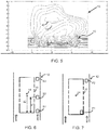
- Figure 5 shows that if a non-conducting shield 42 is used above the high voltage electrode 14, the change to the flow pattern is much less significant.
- the use of a non-metallic shield, for the same purpose as the metallic shield, is greatly preferred.
- the invention relates to measures to detect and prevent disadvantageous flow conditions.
- a first aspect relates to the detection of undesired flow conditions.
- a first approach is to measure the flow velocity in the center of the main gas flow channel (for example the region 1 mm ⁇ x ⁇ 4 mm in Figures 3 to 5 ).
- This velocity should not be less than a set fraction of the velocity at the entrance or exit of the main flow channel.
- This set fraction may for example be in the range 0.4 to 0.7, for example 0.4, 0.5 or 0.6.
- Figure 6 shows the particle charging section 12 with a first flow sensor S1 at the inlet side, a second flow sensor S2 between the inlet and outlet sides and a third flow sensor S3 at the outlet side.
- the sensors in this example are all outside the ionization chamber, i.e. in the main air flow channel.
- sensors may be at only one angular position around the annulus, or at multiple positions around the annulus.
- the design does not need to be rotationally symmetric.
- openings may be provided in the top or bottom of the ionization chamber, not only in the side walls.
- the second sensor S2 is generally aligned with the high voltage electrode tip, preferably slightly towards the inlet side so that it is positioned where the greatest flow reduction is experienced as shown in Figure 4 . For example it may be positioned at least 75 % of the way along the section 12 between the inlet and the high voltage electrode tip.
- the distance d1 is the distance of the flow sensor from the inlet end of the ionization chamber (in particular the component parallel to the general flow direction) and the distance d2 is the distance of the tip of the ionization electrode from the inlet end of the ionization chamber.
- Figure 7 shows the particle charging section 12 with a first pressure sensor PI at the inlet end of the ionization chamber, at a corner (for measuring p cor ), and a second pressure sensor P2 at the main channel exit (for measuring p exit ).
- a second aspect relates to how to change the operation of the sensor when adverse flow conditions have been detected.
- the current delivered to the high voltage electrode may be reduced depending on the measured signals, i.e. the relative flow velocities or pressure differences.
- the high voltage electrode drive voltage V cor is variable by a controller 27 as shown in Figures 1 and 2 , and it may be adjusted making use of the information from the flow sensor arrangement.
- the flow rate thought the particle sensor may additionally or alternatively be controlled to influence the flow conditions.
- the measures above relate to the detection and prevention of undesired flow conditions. It is also possible to design the system to prevent and reduce the occurrence of the undesired flow conditions.
- Design rules for example include:
- the sensor arrangement may be considered generally to be a "flow sensor arrangement" in that the sensed signals are influenced by flow conditions, or it may be considered to be a "flow and/or pressure sensor arrangement". It may comprise flow rate sensors or pressure sensors or combinations of these, each of which provide measurements which relate generally to flow conditions. There may be sensor elements inside and/or outside the ionization chamber.
- One example has been given of a pressure sensor inside the chamber, but other examples may provide one or more flow rate sensors inside the ionization chamber.
- the aim is essentially to be able to distinguish between flows of the general type shown in Figure 3 and those of the general type shown in Figure 4 .
- Various combinations of pressure sensors and flow rate sensors may be used to achieve this. Instead of (or as well as) sensing flow rate, it is possible to sense flow speed for example using a hot wire anemometer.
- precipitation section Two examples have been shown. However, there are other examples. For example, it is known to provide both a filter precipitation stage and an electrostatic stage so that multiple measurements are obtained - one with the electrostatic stage actuated and one with the electrostatic stage deactivated. This enables determination of both the number-averaged particle diameter and the particle number concentration.
Landscapes
- Chemical & Material Sciences (AREA)
- General Physics & Mathematics (AREA)
- Physics & Mathematics (AREA)
- Biochemistry (AREA)
- Life Sciences & Earth Sciences (AREA)
- Analytical Chemistry (AREA)
- Health & Medical Sciences (AREA)
- General Health & Medical Sciences (AREA)
- Dispersion Chemistry (AREA)
- Immunology (AREA)
- Pathology (AREA)
- Fluid Mechanics (AREA)
- Other Investigation Or Analysis Of Materials By Electrical Means (AREA)
- Electrostatic Separation (AREA)
Applications Claiming Priority (2)
| Application Number | Priority Date | Filing Date | Title |
|---|---|---|---|
| EP15175272 | 2015-07-03 | ||
| PCT/EP2016/065072 WO2017005560A1 (en) | 2015-07-03 | 2016-06-29 | A particle sensor and particle sensing method |
Publications (2)
| Publication Number | Publication Date |
|---|---|
| EP3317640A1 EP3317640A1 (en) | 2018-05-09 |
| EP3317640B1 true EP3317640B1 (en) | 2021-01-13 |
Family
ID=53514051
Family Applications (1)
| Application Number | Title | Priority Date | Filing Date |
|---|---|---|---|
| EP16733497.8A Active EP3317640B1 (en) | 2015-07-03 | 2016-06-29 | A particle sensor and particle sensing method |
Country Status (5)
| Country | Link |
|---|---|
| US (1) | US10508982B2 (https=) |
| EP (1) | EP3317640B1 (https=) |
| JP (1) | JP6797846B2 (https=) |
| CN (1) | CN107872986B (https=) |
| WO (1) | WO2017005560A1 (https=) |
Families Citing this family (8)
| Publication number | Priority date | Publication date | Assignee | Title |
|---|---|---|---|---|
| JP6730154B2 (ja) * | 2016-09-28 | 2020-07-29 | 日本特殊陶業株式会社 | 微粒子測定装置および微粒子測定システム |
| JP6730155B2 (ja) * | 2016-09-29 | 2020-07-29 | 日本特殊陶業株式会社 | 微粒子測定装置および微粒子測定システム |
| WO2019037042A1 (en) * | 2017-08-24 | 2019-02-28 | Honeywell International Inc. | AIRFLOW REGULATION FOR PARTICLE SENSOR |
| CN108896454B (zh) * | 2018-09-18 | 2023-05-16 | 大连海事大学 | 一种基于时分复用技术的多通道磨粒检测方法及装置 |
| DE102018218918A1 (de) * | 2018-11-06 | 2020-05-07 | Robert Bosch Gmbh | Partikelsensor und Betriebsverfahren hierfür |
| US11433154B2 (en) | 2020-05-18 | 2022-09-06 | Wangs Alliance Corporation | Germicidal lighting |
| US11027038B1 (en) | 2020-05-22 | 2021-06-08 | Delta T, Llc | Fan for improving air quality |
| US20220282877A1 (en) * | 2021-03-03 | 2022-09-08 | Apicem Technology Services Company Limited | Air purifying system |
Family Cites Families (17)
| Publication number | Priority date | Publication date | Assignee | Title |
|---|---|---|---|---|
| JPS5048990A (https=) * | 1973-08-31 | 1975-05-01 | ||
| JPS539874B2 (https=) * | 1973-12-05 | 1978-04-08 | ||
| JPH0652233B2 (ja) * | 1985-08-21 | 1994-07-06 | 閃一 増田 | 超微粒子測定装置 |
| US4769609A (en) * | 1986-09-19 | 1988-09-06 | Senichi Masuda | Measurement of ultra-fine particles utilizing pulsed corona signals |
| JP3211317B2 (ja) * | 1991-12-27 | 2001-09-25 | 株式会社デンソー | 混合ガスの計測方法及び装置 |
| EP1781481B1 (en) * | 2004-08-11 | 2009-04-15 | Koninklijke Philips Electronics N.V. | Air pollution sensor system |
| JP2008510135A (ja) * | 2004-08-11 | 2008-04-03 | コーニンクレッカ フィリップス エレクトロニクス エヌ ヴィ | 空気汚染センサシステム |
| JP2008544294A (ja) * | 2005-06-28 | 2008-12-04 | コーニンクレッカ フィリップス エレクトロニクス エヌ ヴィ | 超微細粒子センサ |
| KR100614101B1 (ko) * | 2005-09-15 | 2006-08-22 | 한국과학기술연구원 | 입자 계수기 |
| EP1914537A1 (en) * | 2006-10-17 | 2008-04-23 | Ibiden Co., Ltd. | Particulate matter sensor |
| US8402815B2 (en) | 2007-04-06 | 2013-03-26 | Koninklijke Philips Electronics N.V. | Air pollution sensor system |
| US8539840B2 (en) * | 2008-02-05 | 2013-09-24 | Enertechnix, Inc | Aerosol collection apparatus and methods |
| FI20080182A0 (fi) * | 2008-03-04 | 2008-03-04 | Navaro 245 Oy | Mittausmenetelmä ja -laite |
| EP2370802B1 (en) * | 2008-11-25 | 2017-07-26 | Koninklijke Philips N.V. | Sensor for sensing airborne particles |
| WO2012069963A1 (en) * | 2010-11-26 | 2012-05-31 | Koninklijke Philips Electronics N.V. | Sensor for assessing air pollution |
| KR200484692Y1 (ko) * | 2012-02-18 | 2017-10-18 | 페가소 오와이 | 확인된 공기 흐름을 생성하기 위한 장치 및 방법, 및 확인된 공기 흐름의 입자 농도 측정에서의 그러한 장치의 용도 |
| EP2815473A1 (en) * | 2012-02-18 | 2014-12-24 | Pegasor OY | Apparatus and process for producing acknowledged air flow and the use of such apparatus in measuring particle concentration in acknowledged air flow |
-
2016
- 2016-06-29 EP EP16733497.8A patent/EP3317640B1/en active Active
- 2016-06-29 US US15/736,832 patent/US10508982B2/en active Active
- 2016-06-29 WO PCT/EP2016/065072 patent/WO2017005560A1/en not_active Ceased
- 2016-06-29 CN CN201680039511.1A patent/CN107872986B/zh active Active
- 2016-06-29 JP JP2017567411A patent/JP6797846B2/ja active Active
Non-Patent Citations (1)
| Title |
|---|
| None * |
Also Published As
| Publication number | Publication date |
|---|---|
| JP6797846B2 (ja) | 2020-12-09 |
| CN107872986A (zh) | 2018-04-03 |
| JP2018528400A (ja) | 2018-09-27 |
| CN107872986B (zh) | 2020-04-14 |
| US20180164203A1 (en) | 2018-06-14 |
| WO2017005560A1 (en) | 2017-01-12 |
| EP3317640A1 (en) | 2018-05-09 |
| US10508982B2 (en) | 2019-12-17 |
Similar Documents
| Publication | Publication Date | Title |
|---|---|---|
| EP3317640B1 (en) | A particle sensor and particle sensing method | |
| EP2370802B1 (en) | Sensor for sensing airborne particles | |
| JP5480157B2 (ja) | 気流における帯電浮遊粒子のサイズ分布を特徴付けるデバイス | |
| EP2815226B1 (en) | Apparatus and process for producing air flow and the use of such apparatus in measuring particle concentration in air flow | |
| EP3548183B1 (en) | Electrostatic particle filtering | |
| CN104170190B (zh) | 产生已知气流的装置和过程及使用该装置在已知气流中测量颗粒浓度 | |
| JP5480156B2 (ja) | 空気流動中の帯電した浮遊粒子のサイズ分布の特性を決定する装置 | |
| JPWO2007072942A1 (ja) | 分級装置及び微粒子測定装置 | |
| KR102641561B1 (ko) | 미세먼지 질량 농도 측정 시스템 | |
| EP3308138B1 (en) | Method of designing a particle sensor and particle sensing method | |
| JP2018528400A5 (https=) | ||
| WO2009118821A1 (ja) | 微粒子測定装置 | |
| KR102215223B1 (ko) | 미세먼지 측정장치 | |
| CN212674718U (zh) | 细悬浮颗粒物检测装置 | |
| KR20080083854A (ko) | 가변형 입경 분리기 | |
| CA3149617A1 (en) | Particle sensor and sensing method | |
| CN114264579A (zh) | 细悬浮颗粒物检测装置 |
Legal Events
| Date | Code | Title | Description |
|---|---|---|---|
| STAA | Information on the status of an ep patent application or granted ep patent |
Free format text: STATUS: THE INTERNATIONAL PUBLICATION HAS BEEN MADE |
|
| PUAI | Public reference made under article 153(3) epc to a published international application that has entered the european phase |
Free format text: ORIGINAL CODE: 0009012 |
|
| STAA | Information on the status of an ep patent application or granted ep patent |
Free format text: STATUS: REQUEST FOR EXAMINATION WAS MADE |
|
| 17P | Request for examination filed |
Effective date: 20180205 |
|
| AK | Designated contracting states |
Kind code of ref document: A1 Designated state(s): AL AT BE BG CH CY CZ DE DK EE ES FI FR GB GR HR HU IE IS IT LI LT LU LV MC MK MT NL NO PL PT RO RS SE SI SK SM TR |
|
| AX | Request for extension of the european patent |
Extension state: BA ME |
|
| DAV | Request for validation of the european patent (deleted) | ||
| DAX | Request for extension of the european patent (deleted) | ||
| RAP1 | Party data changed (applicant data changed or rights of an application transferred) |
Owner name: KONINKLIJKE PHILIPS N.V. |
|
| GRAP | Despatch of communication of intention to grant a patent |
Free format text: ORIGINAL CODE: EPIDOSNIGR1 |
|
| STAA | Information on the status of an ep patent application or granted ep patent |
Free format text: STATUS: GRANT OF PATENT IS INTENDED |
|
| INTG | Intention to grant announced |
Effective date: 20200807 |
|
| GRAS | Grant fee paid |
Free format text: ORIGINAL CODE: EPIDOSNIGR3 |
|
| GRAA | (expected) grant |
Free format text: ORIGINAL CODE: 0009210 |
|
| STAA | Information on the status of an ep patent application or granted ep patent |
Free format text: STATUS: THE PATENT HAS BEEN GRANTED |
|
| AK | Designated contracting states |
Kind code of ref document: B1 Designated state(s): AL AT BE BG CH CY CZ DE DK EE ES FI FR GB GR HR HU IE IS IT LI LT LU LV MC MK MT NL NO PL PT RO RS SE SI SK SM TR |
|
| REG | Reference to a national code |
Ref country code: GB Ref legal event code: FG4D |
|
| REG | Reference to a national code |
Ref country code: CH Ref legal event code: EP |
|
| REG | Reference to a national code |
Ref country code: IE Ref legal event code: FG4D |
|
| REG | Reference to a national code |
Ref country code: DE Ref legal event code: R096 Ref document number: 602016051374 Country of ref document: DE |
|
| REG | Reference to a national code |
Ref country code: AT Ref legal event code: REF Ref document number: 1354937 Country of ref document: AT Kind code of ref document: T Effective date: 20210215 |
|
| REG | Reference to a national code |
Ref country code: AT Ref legal event code: MK05 Ref document number: 1354937 Country of ref document: AT Kind code of ref document: T Effective date: 20210113 |
|
| REG | Reference to a national code |
Ref country code: NL Ref legal event code: MP Effective date: 20210113 |
|
| REG | Reference to a national code |
Ref country code: LT Ref legal event code: MG9D |
|
| PG25 | Lapsed in a contracting state [announced via postgrant information from national office to epo] |
Ref country code: LT Free format text: LAPSE BECAUSE OF FAILURE TO SUBMIT A TRANSLATION OF THE DESCRIPTION OR TO PAY THE FEE WITHIN THE PRESCRIBED TIME-LIMIT Effective date: 20210113 Ref country code: BG Free format text: LAPSE BECAUSE OF FAILURE TO SUBMIT A TRANSLATION OF THE DESCRIPTION OR TO PAY THE FEE WITHIN THE PRESCRIBED TIME-LIMIT Effective date: 20210413 Ref country code: PT Free format text: LAPSE BECAUSE OF FAILURE TO SUBMIT A TRANSLATION OF THE DESCRIPTION OR TO PAY THE FEE WITHIN THE PRESCRIBED TIME-LIMIT Effective date: 20210513 Ref country code: NO Free format text: LAPSE BECAUSE OF FAILURE TO SUBMIT A TRANSLATION OF THE DESCRIPTION OR TO PAY THE FEE WITHIN THE PRESCRIBED TIME-LIMIT Effective date: 20210413 Ref country code: FI Free format text: LAPSE BECAUSE OF FAILURE TO SUBMIT A TRANSLATION OF THE DESCRIPTION OR TO PAY THE FEE WITHIN THE PRESCRIBED TIME-LIMIT Effective date: 20210113 Ref country code: HR Free format text: LAPSE BECAUSE OF FAILURE TO SUBMIT A TRANSLATION OF THE DESCRIPTION OR TO PAY THE FEE WITHIN THE PRESCRIBED TIME-LIMIT Effective date: 20210113 Ref country code: GR Free format text: LAPSE BECAUSE OF FAILURE TO SUBMIT A TRANSLATION OF THE DESCRIPTION OR TO PAY THE FEE WITHIN THE PRESCRIBED TIME-LIMIT Effective date: 20210414 |
|
| PG25 | Lapsed in a contracting state [announced via postgrant information from national office to epo] |
Ref country code: SE Free format text: LAPSE BECAUSE OF FAILURE TO SUBMIT A TRANSLATION OF THE DESCRIPTION OR TO PAY THE FEE WITHIN THE PRESCRIBED TIME-LIMIT Effective date: 20210113 Ref country code: AT Free format text: LAPSE BECAUSE OF FAILURE TO SUBMIT A TRANSLATION OF THE DESCRIPTION OR TO PAY THE FEE WITHIN THE PRESCRIBED TIME-LIMIT Effective date: 20210113 Ref country code: RS Free format text: LAPSE BECAUSE OF FAILURE TO SUBMIT A TRANSLATION OF THE DESCRIPTION OR TO PAY THE FEE WITHIN THE PRESCRIBED TIME-LIMIT Effective date: 20210113 Ref country code: LV Free format text: LAPSE BECAUSE OF FAILURE TO SUBMIT A TRANSLATION OF THE DESCRIPTION OR TO PAY THE FEE WITHIN THE PRESCRIBED TIME-LIMIT Effective date: 20210113 Ref country code: PL Free format text: LAPSE BECAUSE OF FAILURE TO SUBMIT A TRANSLATION OF THE DESCRIPTION OR TO PAY THE FEE WITHIN THE PRESCRIBED TIME-LIMIT Effective date: 20210113 |
|
| PG25 | Lapsed in a contracting state [announced via postgrant information from national office to epo] |
Ref country code: IS Free format text: LAPSE BECAUSE OF FAILURE TO SUBMIT A TRANSLATION OF THE DESCRIPTION OR TO PAY THE FEE WITHIN THE PRESCRIBED TIME-LIMIT Effective date: 20210513 |
|
| REG | Reference to a national code |
Ref country code: DE Ref legal event code: R097 Ref document number: 602016051374 Country of ref document: DE |
|
| PG25 | Lapsed in a contracting state [announced via postgrant information from national office to epo] |
Ref country code: EE Free format text: LAPSE BECAUSE OF FAILURE TO SUBMIT A TRANSLATION OF THE DESCRIPTION OR TO PAY THE FEE WITHIN THE PRESCRIBED TIME-LIMIT Effective date: 20210113 Ref country code: CZ Free format text: LAPSE BECAUSE OF FAILURE TO SUBMIT A TRANSLATION OF THE DESCRIPTION OR TO PAY THE FEE WITHIN THE PRESCRIBED TIME-LIMIT Effective date: 20210113 Ref country code: SM Free format text: LAPSE BECAUSE OF FAILURE TO SUBMIT A TRANSLATION OF THE DESCRIPTION OR TO PAY THE FEE WITHIN THE PRESCRIBED TIME-LIMIT Effective date: 20210113 |
|
| PLBE | No opposition filed within time limit |
Free format text: ORIGINAL CODE: 0009261 |
|
| STAA | Information on the status of an ep patent application or granted ep patent |
Free format text: STATUS: NO OPPOSITION FILED WITHIN TIME LIMIT |
|
| PG25 | Lapsed in a contracting state [announced via postgrant information from national office to epo] |
Ref country code: DK Free format text: LAPSE BECAUSE OF FAILURE TO SUBMIT A TRANSLATION OF THE DESCRIPTION OR TO PAY THE FEE WITHIN THE PRESCRIBED TIME-LIMIT Effective date: 20210113 Ref country code: RO Free format text: LAPSE BECAUSE OF FAILURE TO SUBMIT A TRANSLATION OF THE DESCRIPTION OR TO PAY THE FEE WITHIN THE PRESCRIBED TIME-LIMIT Effective date: 20210113 Ref country code: SK Free format text: LAPSE BECAUSE OF FAILURE TO SUBMIT A TRANSLATION OF THE DESCRIPTION OR TO PAY THE FEE WITHIN THE PRESCRIBED TIME-LIMIT Effective date: 20210113 |
|
| 26N | No opposition filed |
Effective date: 20211014 |
|
| PG25 | Lapsed in a contracting state [announced via postgrant information from national office to epo] |
Ref country code: MC Free format text: LAPSE BECAUSE OF FAILURE TO SUBMIT A TRANSLATION OF THE DESCRIPTION OR TO PAY THE FEE WITHIN THE PRESCRIBED TIME-LIMIT Effective date: 20210113 Ref country code: AL Free format text: LAPSE BECAUSE OF FAILURE TO SUBMIT A TRANSLATION OF THE DESCRIPTION OR TO PAY THE FEE WITHIN THE PRESCRIBED TIME-LIMIT Effective date: 20210113 Ref country code: ES Free format text: LAPSE BECAUSE OF FAILURE TO SUBMIT A TRANSLATION OF THE DESCRIPTION OR TO PAY THE FEE WITHIN THE PRESCRIBED TIME-LIMIT Effective date: 20210113 |
|
| REG | Reference to a national code |
Ref country code: CH Ref legal event code: PL |
|
| PG25 | Lapsed in a contracting state [announced via postgrant information from national office to epo] |
Ref country code: SI Free format text: LAPSE BECAUSE OF FAILURE TO SUBMIT A TRANSLATION OF THE DESCRIPTION OR TO PAY THE FEE WITHIN THE PRESCRIBED TIME-LIMIT Effective date: 20210113 |
|
| REG | Reference to a national code |
Ref country code: BE Ref legal event code: MM Effective date: 20210630 |
|
| PG25 | Lapsed in a contracting state [announced via postgrant information from national office to epo] |
Ref country code: LU Free format text: LAPSE BECAUSE OF NON-PAYMENT OF DUE FEES Effective date: 20210629 |
|
| PG25 | Lapsed in a contracting state [announced via postgrant information from national office to epo] |
Ref country code: LI Free format text: LAPSE BECAUSE OF NON-PAYMENT OF DUE FEES Effective date: 20210630 Ref country code: IT Free format text: LAPSE BECAUSE OF FAILURE TO SUBMIT A TRANSLATION OF THE DESCRIPTION OR TO PAY THE FEE WITHIN THE PRESCRIBED TIME-LIMIT Effective date: 20210113 Ref country code: IE Free format text: LAPSE BECAUSE OF NON-PAYMENT OF DUE FEES Effective date: 20210629 Ref country code: CH Free format text: LAPSE BECAUSE OF NON-PAYMENT OF DUE FEES Effective date: 20210630 |
|
| PG25 | Lapsed in a contracting state [announced via postgrant information from national office to epo] |
Ref country code: IS Free format text: LAPSE BECAUSE OF FAILURE TO SUBMIT A TRANSLATION OF THE DESCRIPTION OR TO PAY THE FEE WITHIN THE PRESCRIBED TIME-LIMIT Effective date: 20210513 |
|
| PG25 | Lapsed in a contracting state [announced via postgrant information from national office to epo] |
Ref country code: BE Free format text: LAPSE BECAUSE OF NON-PAYMENT OF DUE FEES Effective date: 20210630 |
|
| PG25 | Lapsed in a contracting state [announced via postgrant information from national office to epo] |
Ref country code: NL Free format text: LAPSE BECAUSE OF NON-PAYMENT OF DUE FEES Effective date: 20210113 Ref country code: CY Free format text: LAPSE BECAUSE OF FAILURE TO SUBMIT A TRANSLATION OF THE DESCRIPTION OR TO PAY THE FEE WITHIN THE PRESCRIBED TIME-LIMIT Effective date: 20210113 |
|
| PG25 | Lapsed in a contracting state [announced via postgrant information from national office to epo] |
Ref country code: HU Free format text: LAPSE BECAUSE OF FAILURE TO SUBMIT A TRANSLATION OF THE DESCRIPTION OR TO PAY THE FEE WITHIN THE PRESCRIBED TIME-LIMIT; INVALID AB INITIO Effective date: 20160629 |
|
| PG25 | Lapsed in a contracting state [announced via postgrant information from national office to epo] |
Ref country code: MK Free format text: LAPSE BECAUSE OF FAILURE TO SUBMIT A TRANSLATION OF THE DESCRIPTION OR TO PAY THE FEE WITHIN THE PRESCRIBED TIME-LIMIT Effective date: 20210113 |
|
| PG25 | Lapsed in a contracting state [announced via postgrant information from national office to epo] |
Ref country code: MT Free format text: LAPSE BECAUSE OF FAILURE TO SUBMIT A TRANSLATION OF THE DESCRIPTION OR TO PAY THE FEE WITHIN THE PRESCRIBED TIME-LIMIT Effective date: 20210113 |
|
| PGFP | Annual fee paid to national office [announced via postgrant information from national office to epo] |
Ref country code: DE Payment date: 20250626 Year of fee payment: 10 |
|
| PGFP | Annual fee paid to national office [announced via postgrant information from national office to epo] |
Ref country code: GB Payment date: 20250617 Year of fee payment: 10 |
|
| PGFP | Annual fee paid to national office [announced via postgrant information from national office to epo] |
Ref country code: FR Payment date: 20250624 Year of fee payment: 10 |
|
| PG25 | Lapsed in a contracting state [announced via postgrant information from national office to epo] |
Ref country code: TR Free format text: LAPSE BECAUSE OF FAILURE TO SUBMIT A TRANSLATION OF THE DESCRIPTION OR TO PAY THE FEE WITHIN THE PRESCRIBED TIME-LIMIT Effective date: 20210113 |