EP3317002B1 - Engagement of gas cylinder with gas dispenser - Google Patents
Engagement of gas cylinder with gas dispenser Download PDFInfo
- Publication number
- EP3317002B1 EP3317002B1 EP16741192.5A EP16741192A EP3317002B1 EP 3317002 B1 EP3317002 B1 EP 3317002B1 EP 16741192 A EP16741192 A EP 16741192A EP 3317002 B1 EP3317002 B1 EP 3317002B1
- Authority
- EP
- European Patent Office
- Prior art keywords
- gas
- cylinder
- holder
- gas cylinder
- outlet
- Prior art date
- Legal status (The legal status is an assumption and is not a legal conclusion. Google has not performed a legal analysis and makes no representation as to the accuracy of the status listed.)
- Active
Links
Images




Classifications
-
- F—MECHANICAL ENGINEERING; LIGHTING; HEATING; WEAPONS; BLASTING
- F17—STORING OR DISTRIBUTING GASES OR LIQUIDS
- F17C—VESSELS FOR CONTAINING OR STORING COMPRESSED, LIQUEFIED OR SOLIDIFIED GASES; FIXED-CAPACITY GAS-HOLDERS; FILLING VESSELS WITH, OR DISCHARGING FROM VESSELS, COMPRESSED, LIQUEFIED, OR SOLIDIFIED GASES
- F17C5/00—Methods or apparatus for filling containers with liquefied, solidified, or compressed gases under pressures
- F17C5/06—Methods or apparatus for filling containers with liquefied, solidified, or compressed gases under pressures for filling with compressed gases
-
- B—PERFORMING OPERATIONS; TRANSPORTING
- B01—PHYSICAL OR CHEMICAL PROCESSES OR APPARATUS IN GENERAL
- B01F—MIXING, e.g. DISSOLVING, EMULSIFYING OR DISPERSING
- B01F23/00—Mixing according to the phases to be mixed, e.g. dispersing or emulsifying
- B01F23/20—Mixing gases with liquids
- B01F23/23—Mixing gases with liquids by introducing gases into liquid media, e.g. for producing aerated liquids
- B01F23/236—Mixing gases with liquids by introducing gases into liquid media, e.g. for producing aerated liquids specially adapted for aerating or carbonating beverages
- B01F23/2361—Mixing gases with liquids by introducing gases into liquid media, e.g. for producing aerated liquids specially adapted for aerating or carbonating beverages within small containers, e.g. within bottles
-
- B—PERFORMING OPERATIONS; TRANSPORTING
- B67—OPENING, CLOSING OR CLEANING BOTTLES, JARS OR SIMILAR CONTAINERS; LIQUID HANDLING
- B67D—DISPENSING, DELIVERING OR TRANSFERRING LIQUIDS, NOT OTHERWISE PROVIDED FOR
- B67D1/00—Apparatus or devices for dispensing beverages on draught
- B67D1/04—Apparatus utilising compressed air or other gas acting directly or indirectly on beverages in storage containers
- B67D1/0412—Apparatus utilising compressed air or other gas acting directly or indirectly on beverages in storage containers the whole dispensing unit being fixed to the container
- B67D1/0418—Apparatus utilising compressed air or other gas acting directly or indirectly on beverages in storage containers the whole dispensing unit being fixed to the container comprising a CO2 cartridge for dispensing and carbonating the beverage
-
- F—MECHANICAL ENGINEERING; LIGHTING; HEATING; WEAPONS; BLASTING
- F17—STORING OR DISTRIBUTING GASES OR LIQUIDS
- F17C—VESSELS FOR CONTAINING OR STORING COMPRESSED, LIQUEFIED OR SOLIDIFIED GASES; FIXED-CAPACITY GAS-HOLDERS; FILLING VESSELS WITH, OR DISCHARGING FROM VESSELS, COMPRESSED, LIQUEFIED, OR SOLIDIFIED GASES
- F17C2201/00—Vessel construction, in particular geometry, arrangement or size
- F17C2201/05—Size
- F17C2201/058—Size portable (<30 l)
-
- F—MECHANICAL ENGINEERING; LIGHTING; HEATING; WEAPONS; BLASTING
- F17—STORING OR DISTRIBUTING GASES OR LIQUIDS
- F17C—VESSELS FOR CONTAINING OR STORING COMPRESSED, LIQUEFIED OR SOLIDIFIED GASES; FIXED-CAPACITY GAS-HOLDERS; FILLING VESSELS WITH, OR DISCHARGING FROM VESSELS, COMPRESSED, LIQUEFIED, OR SOLIDIFIED GASES
- F17C2205/00—Vessel construction, in particular mounting arrangements, attachments or identifications means
- F17C2205/03—Fluid connections, filters, valves, closure means or other attachments
- F17C2205/0302—Fittings, valves, filters, or components in connection with the gas storage device
- F17C2205/0323—Valves
-
- F—MECHANICAL ENGINEERING; LIGHTING; HEATING; WEAPONS; BLASTING
- F17—STORING OR DISTRIBUTING GASES OR LIQUIDS
- F17C—VESSELS FOR CONTAINING OR STORING COMPRESSED, LIQUEFIED OR SOLIDIFIED GASES; FIXED-CAPACITY GAS-HOLDERS; FILLING VESSELS WITH, OR DISCHARGING FROM VESSELS, COMPRESSED, LIQUEFIED, OR SOLIDIFIED GASES
- F17C2205/00—Vessel construction, in particular mounting arrangements, attachments or identifications means
- F17C2205/03—Fluid connections, filters, valves, closure means or other attachments
- F17C2205/0302—Fittings, valves, filters, or components in connection with the gas storage device
- F17C2205/0338—Pressure regulators
-
- F—MECHANICAL ENGINEERING; LIGHTING; HEATING; WEAPONS; BLASTING
- F17—STORING OR DISTRIBUTING GASES OR LIQUIDS
- F17C—VESSELS FOR CONTAINING OR STORING COMPRESSED, LIQUEFIED OR SOLIDIFIED GASES; FIXED-CAPACITY GAS-HOLDERS; FILLING VESSELS WITH, OR DISCHARGING FROM VESSELS, COMPRESSED, LIQUEFIED, OR SOLIDIFIED GASES
- F17C2270/00—Applications
- F17C2270/01—Applications for fluid transport or storage
Definitions
- This invention relates generally to engaging a pressurized gas cylinder with a gas dispenser, such as a beverage extractor used in dispensing of wine from a wine bottle.
- a gas dispenser such as a beverage extractor used in dispensing of wine from a wine bottle.
- a wide range of devices employ pressurized gas cylinders, including beverage extractors like that described in U.S. Patent 8,225,959 , cork removers like that in U.S. Patent 5,020,395 , beverage carbonators like that in U.S. Patent 4,867,209 , medical fluid delivery systems as in U.S. Patent 5,163,909 , as well as others including tire inflation devices, pellet guns, etc.
- Gas cylinders are engaged with a receiver of these devices in different ways to deliver pressurized gas to the device.
- the gas cylinder has a threaded neck that is screwed into a threaded hole of a receiver.
- Patent 4,867,209 the gas cylinder is placed in a cap which is threaded onto a body to engage the cylinder with a receiver.
- U.S. Patent 5,163,909 a lever operated toggle mechanism forces a cylinder held in a cradle into engagement with a receiver.
- DE 40 09 248 relates to a battery for gas-capsules.
- US 2,805,846 relates to a device for carbonating beverages.
- cylinder engagement approaches like those above can present difficulties in some circumstances.
- some systems are not tolerant of cylinders that vary in size, e.g., in length and/or diameter, and may not properly seat a cylinder that is outside of an expected size range.
- users may not appreciate exactly how much to tighten the cylinder or cap, resulting in a loose, connection (which may leak) or overtighening (which may cause damage to seal and/or thread components).
- One or more aspects of the invention allow a gas dispensing system to be tolerant of cylinder size variations while still providing for a suitable sealing engagement of the cylinder with a receiver. Moreover, one or more aspects of the invention may ensure proper tightening or other action to properly engage a cylinder with a receiver while minimizing the potential for creating a loose or over-tight connection. Yet other aspects of the invention may help avoid the attempt to reuse an empty or used cylinder.
- An element is used to apply a force to a gas cylinder to engage the cylinder with a receiver of a gas dispensing device. Such engagement involves piercing of a gas outlet of the cylinder and sealingly engaging the cylinder with the receiver (e.g., to resist leaking of gas in an unwanted way).
- the resilient element may deform as needed to accommodate differently sized and/or shaped cylinders while applying a relatively consistent engagement force to the different cylinders.
- deformation of the resilient element may compensate for over-rotation of a cap in a device like that in U.S. Patent 4,867,209 .
- some embodiments may allow a user to thread a cap like that in U.S. Patent 4,867,209 to a stop where no further threading of the cap is permitted, and yet ensure proper engagement of the cylinder even in the case of cylinders that are shorter or longer than standard.
- the invention consists of a device according to claim 1 and a method according to claim 10.
- a rigid force transmitter may be positioned between the resilient element and the cylinder that provides a contact area between the force transmitter and the resilient element.
- the force transmitter may be arranged so that the contact area has a same size for different cylinders that have different sizes, shapes, etc.
- the force transmitter may include a rigid, flat plate positioned on the resilient element and that contacts a bottom of a cylinder to transmit force of the holder to the cylinder.
- the holder may include a threaded portion arranged to engage with a threaded portion of the body, with the threaded portion of the holder being located near a top of the holder and the resilient element located near a bottom of the holder.
- the holder may have a cup shape with an opening at the top of the holder and an interior space, and the resilient element may be located in the interior space near the bottom of the holder.
- the holder may be movable relative to the body to a stop which prevents further rotation of the holder relative to the body.
- the resilient element may be arranged to plastically deform with force transmitted to the gas cylinder suitable to cause the piercing element to pierce the gas outlet.
- the resilient element may be suitable only for a single use.
- the resilient element may be attached to the bottom of the gas cylinder, and may include a piece of elastomeric material.
- the gas dispenser may include a regulator to regulate a pressure of gas delivered to the gas dispensing outlet and a valve to control flow of gas from the regulator to the gas dispensing outlet.
- the dispenser may be part of a beverage extractor that has a needle attached to the body and in fluid communication with the gas dispensing outlet.
- the needle may have a lumen and be arranged to be inserted through a cork of a wine bottle so as to deliver pressurized gas from the gas dispensing outlet to an interior of the bottle.
- the needle may additionally be arranged to conduct a flow of wine through the needle to a wine outlet of the body, and the body may include a valve arranged to control flow of wine from the needle to the wine outlet.
- the gas dispensing device need not include a cylinder holder, and instead may include any suitable type of cylinder drive arranged to move the gas cylinder and the receiver toward each other so as to force the neck of the gas cylinder into engagement with the receiver.
- the cylinder drive may include a linkage, a toggle, hydraulic or pneumatic piston, motor drive, screw, etc.
- the resilient element may be arranged to transmit force of the cylinder drive to the gas cylinder to force the neck of the received gas cylinder into engagement with the receiver.
- the steps of moving and sealingly engaging comprise threading a holder holding the gas cylinder and the resilient element onto a body to which the receiver is attached.
- One or more embodiments in accordance with aspects of the invention allow a user to withdraw or otherwise extract a beverage, such as wine, from within a bottle that is sealed by a cork, plug, elastomeric septum or other closure without removing the closure.
- a beverage such as wine
- removal of liquid from such a bottle may be performed one or more times, yet the closure may remain in place during and after each beverage extraction to maintain a seal for the bottle.
- the beverage may be dispensed from the bottle multiple times and stored for extended periods between each extraction with little or no effect on beverage quality.
- little or no gas, such as air which is reactive with the beverage may be introduced into the bottle either during or after extraction of beverage from within the bottle.
- a user may withdraw wine from a wine bottle without removal of, or damage to, the cork, and without allowing air or other potentially damaging gasses or liquids entry into the bottle.
- FIG. 1 shows a schematic diagram of a gas delivery device 1 that incorporates one or more aspects of the invention.
- the gas delivery device 1 includes a body 3 that has a gas dispensing outlet 37, which may take a variety of different forms depending on the purpose of the gas delivery device 1.
- the gas dispensing outlet 37 may be arranged to couple with a tire valve stem to deliver pressurized gas to the tire.
- the device 1 may be arranged to pressurize the inside of a cork-stoppered bottle to remove the cork.
- a needle (not shown) may be attached at the gas dispensing outlet 37 so that gas can be delivered to an internal lumen of the needle.
- the needle may be inserted through the bottle cork so gas is delivered via the needle lumen to the bottle interior to expel the cork.
- Other gas delivery devices are possible, such as for use in pellet guns, medical fluid delivery devices, beverage carbonation devices, etc.
- the dispensing outlet 37 need not necessarily be exposed at an exterior of the device 1, but rather may lead to other components of the device, such as a needle, valve, conduit, reservoir, etc.
- the device 1 includes a receiver 34 attached to the body 3 that is arranged to couple with a gas cylinder 100 to receive gas from the cylinder 100.
- the receiver 34 includes a piercing element 35 arranged to pierce a gas outlet 102 of the cylinder 100 as the neck 101 of the cylinder 100 is moved toward the receiver 34. That is, as the neck 101 of the cylinder 100 is moved into an opening of the receiver 34, the piercing element 35 may penetrate the gas outlet 102, which may be a metal cap that seals the cylinder closed, containing relatively high pressure gas, e.g., 20.685 MPa (3000 psi) or less.
- a gasket 36 may be used to create a gas-tight seal between the neck 101 and the receiver 34, e.g., so that gas does not leak from the cylinder 100 in an unwanted way.
- the cylinder 100 may deliver pressurized gas to a passageway through or near the piercing element 35.
- the piercing element 35 and gasket 36 are shown assembled with the receiver 34, either or both of the piercing element 35 and the gasket 36 may be assembled with the cylinder 100, or be separate components from both the receiver 34 and the cylinder 100.
- the receiver 34 in this embodiment has an opening that receives the neck 101 of the cylinder 100, such an arrangement is not necessary. Instead, the receiver 34 may be arranged at a flat surface or protrusion of the body 3, for example.
- the gas dispensing device 1 is also shown as including a regulator 600 that is fluidly coupled to the receiver 34 via a passageway or conduit to receive pressurized gas from the gas cylinder 100.
- the regulator 600 may have one or more stages, or otherwise include suitable components, such as one or more valves, to adjust a pressure of gas to a desired range.
- the regulator 600 is optional and may be eliminated since pressure regulation of gas from the cylinder 100 is not required in all aspects.
- the device 1 also is shown with a valve 300 that can control the flow of gas from the receiver 34 to the dispensing outlet 37. Again, the valve 300 is optional, but if included may include any suitable structure or components, such as a valve ball element, gate, spool or other valve structure.
- a filter to filter gas delivered to the outlet 37
- a safety valve to release gas over a certain pressure in the passageway leading from the receiver 34 to the dispensing outlet 37
- a pressure sensor to detect moisture in the passageway leading from the receiver 34 to the dispensing outlet 37
- a moisture separator etc.
- the device 1 includes a cylinder drive 7 arranged to move the gas cylinder 100 and the receiver 34 towards each other so as to mate the cylinder with the receiver.
- a cylinder drive 7 may operate in any suitable way to move the cylinder 100 and receiver 34 toward each other so that gas released by the cylinder 100 is received by the receiver 34.
- the cylinder drive 7 includes a dashed line element coupled between the body 3 and a portion of the drive 7 positioned below a bottom 103 of the cylinder.
- the dashed line element is intended to schematically represent a mechanism or component arranged to move the cylinder 100 and the receiver 34 toward each other, such as a mechanical linkage, a motor drive, a threaded engagement, a magnetic coupling, a clamp, etc.
- force applied by the cylinder drive 7 to move the cylinder 100 and the receiver 34 toward each other is transmitted via a resilient element 5.
- the resilient element 5 contacts a bottom 103 of the cylinder 100, but the resilient element 5 could contact the cylinder 100 in other areas to transmit a motive force, e.g., at the cylinder sides, neck 101 or other portion.
- the resilient element 5 may be arranged to transmit a motive force to the receiver 34, e.g., the resilient element 5 may be positioned between the body 3 and the receiver 34, or may be arranged between portions of the cylinder drive 7, e.g., as a link in a drive linkage.
- the resilient element 5 may allow the device 1 to be more tolerant of size and/or shape variations in gas cylinders 100, e.g., in diameter and/or length.
- gas cylinders 100 e.g., in diameter and/or length.
- the resilient element 5 may accommodate variations in size, shape or other characteristic of cylinders 100.
- the resilient element 5 is arranged to deform when applying force to the cylinder 100 when mating the cylinder 100 with the receiver 34.
- the resilient element 5 may include a spring or elastomeric material arranged so that for cylinders longer than a standard, the resilient element 5 will deform more than usual to compensate for the longer length while still applying a suitable force to cause the cylinder 100 to be properly mated with the receiver 34.
- cylinders that are shorter than the standard may be compensated for because, while the resilient element 5 may deform less than with a relatively long cylinder, the resilient element 5 may still deform even when operating with a "short" cylinder, ensuring that appropriate mating force is applied to the receiver 34 and cylinder 100.
- cylinder size or shape may be accommodated, such as differences in the size or shape of the bottom 103 of cylinders 100.
- the embodiment shown in FIG. 1 may be able to accommodate very different cylinder configurations, such as cylinders with a hemispherical bottom as shown, as well as cylinders with a flat bottom, cylinders with a rectangular tube shape, etc.
- the resilient element 5 may allow for a cylinder drive 7 to be moved to a stop or other defined point in its motion while applying a suitable engagement force to the receiver 34 and cylinder 100.
- This feature may be useful since a user may be assured that the cylinder and receiver are properly engaged by simply operating the cylinder drive 7 to a stop or other defined point.
- the toggle mechanism in U.S. Patent 5,163,909 may work with cylinders having a specific length, but may not operate properly at all if the cylinder is too short, too long, or has other variations in size or shape.
- Patent 5,163,909 that is equipped with a resilient element in accordance with an aspect of the invention may be able to properly engage cylinders of a wider range of different sizes and/or shapes than otherwise possible. Moreover, a user can be ensured that proper engagement of the cylinder with the receiver is achieved by simply fully closing the toggle mechanism.
- FIG. 2 shows an illustrative embodiment in which the cylinder drive 7 includes a holder 71 in the form of a cup-shaped cover.
- the holder 71 has an internal space that receives the cylinder 100 inserted through an opening near a top of the holder 71.
- the holder 71 also includes a threaded portion 72 near the top that is arranged to engage with a corresponding threaded portion 38 on the body 3.
- the cylinder 100 and receiver 34 may be moved toward each other.
- a resilient element 5 may be positioned at a bottom of the interior space of the holder 71 so as to contact the bottom 103 of the cylinder 100.
- the resilient element 5 moves the cylinder 100 upwardly so the cylinder neck 101 is received into an opening of the receiver 34, e.g., so that a piercing element 35 penetrates the gas outlet 102 of the cylinder to release gas.
- a gasket 36 such as an o-ring or other seal, is carried on the cylinder 100 and is arranged to create a suitable seal between the receiver 34 and the cylinder 100.
- the holder 71 may be threaded onto the body 3 until the holder 71 contacts a stop 39 on the body 3 that prevents further threading of the holder 71 onto the body 3.
- the stop 39 and resilient element 5 may be arranged so that when the holder 71 reaches the stop 39, cylinders 100 within a relatively wide range of sizes and/or shapes are suitably engaged with the receiver 34, e.g., so the piercing element 35 pierces the gas outlet 102 and the gasket 36 forms a suitable, leak-resistant seal.
- the cylinder may have a valve at the gas outlet 102 that is opened as the cylinder is mated with the receiver so gas is released without piercing.
- the resilient element 5 may deform so that a bottom 103 of the cylinder 100 is received into the resilient element 5 as shown in dashed line in FIG. 2 .
- a user may be ensured of proper cylinder/receiver engagement by simply threading the holder 71 onto the body 3 until the stop 39 is reached.
- stop arrangements are possible, such as a stop on the holder 71 that contacts a portion of the body 3, the threads on the body 3 and/or holder 71 may terminate so as to function as a stop, a marking on the body and/or holder may indicate a point at which engagement of the holder with the body should be terminated, etc.
- the holder 71 is not limited to engaging the body 3 with a thread, but instead may engage via a bayonet connection, a cam connection, a clamp, etc.
- the resilient element 5 is shown located at a bottom of the interior space of the holder 71 such that a cylinder 100 inserted into the holder 71 rests on the resilient element 5, other arrangements are possible.
- a resilient element 5 may be attached to the bottom 103 of each cylinder 100 so that once the cylinder 100 is placed in a holder 71 like that in FIG. 2 , the resilient element 5 is positioned to transmit force to the cylinder as the holder 71 is engaged with the body 3.
- the resilient element 5 may be removably attached to the cylinder 100, e.g., so that the resilient element 5 can be removed from a used cylinder and placed on a new one, or permanently attached to the cylinder, e.g., so that the resilient element is not usable with another cylinder if removed from a used cylinder.
- the use of a new resilient element 5 with each cylinder may help ensure that proper force is applied to engage the cylinder with the receiver 34, especially as the resilient element 5 deforms plastically during use.
- the resilient element 5 deforms both elastically and plastically when a cylinder 100 is engaged with a receiver 34.
- a resilient element 5 that deforms mostly elastically may allow for repeated use of the resilient element 5 with different cylinders.
- a resilient element 5 that deforms mostly plastically may permit only one-time use of the resilient element 5.
- the resilient element 5 may be arranged to crush or otherwise deform plastically so as to make the element 5 effectively unusable with another cylinder.
- the actuator 32 may be operated by a user to control operation of the valve 300.
- the actuator 32 may include, for example, a push button or lever that a user can move to open and/or close the valve 300.
- the actuator 32 may be operated in other ways, such as by an electromechanical device (such as a solenoid or motor), a pressure sensitive switch, etc.
- the actuator 32 may be used to control gas flow, or for other purposes, such as regulating a gas pressure, causing a piercing element to pierce a cylinder engaged with the receiver, and other functions.
- the cylinder drive 7 may function to simply sealingly engage a cylinder with a receiver, and need not cause gas to be released from a cylinder upon engagement.
- FIGs. 3-9 show an illustrative embodiment of a beverage extraction device 1 that incorporates aspects of the invention.
- a beverage extraction device 1 may be used to extract wine from a wine bottle without removing a cork that seals an opening of the bottle closed.
- the extractor 1 includes a body 3 with a handle 33, that may be gripped by a user for moving the body 3 relative to the base 2 in upward and downward motions to insert a needle 200 through a cork or other closure of a bottle (not shown).
- the body 3 To allow movement of the body 3 relative to the base 2, e.g., for insertion of the needle 200 through a cork, the body 3 includes a rail 31 that has T-shaped cross section, and is arranged to move within a T-shaped receiving slot or channel 21 of the base 2.
- a rail 31 that has T-shaped cross section, and is arranged to move within a T-shaped receiving slot or channel 21 of the base 2.
- other arrangements are possible for engaging the body 3 and base 2 while allowing for movement of the needle 200.
- gas With the needle 200 inserted through a cork, gas can be injected into the bottle to force wine to exit the bottle.
- a lever 32 is provided for operating a valve 300, e.g., to deliver gas to the bottle via the needle 200 so that beverage can be dispensed from an outlet 301.
- the device 1 includes a gas cylinder 100 held by a holder 71 arranged as shown in FIGs. 4 and 5 .
- the resilient element 5 is arranged similarly to that in FIG. 2 , e.g., in the form of a block of elastomeric material having a durometer of about 50-100 on the Shore A scale is located in the holder 71 near a bottom of an interior space of the holder 71, but in this embodiment includes a metal or other non-resilient force transmitter 51 between the cylinder 100 and the resilient element 5.
- FIG. 2 the resilient element 5 is arranged similarly to that in FIG. 2 , e.g., in the form of a block of elastomeric material having a durometer of about 50-100 on the Shore A scale is located in the holder 71 near a bottom of an interior space of the holder 71, but in this embodiment includes a metal or other non-resilient force transmitter 51 between the cylinder 100 and the resilient element 5.
- the force transmitter 51 may be arranged as a flat, solid disc, but may have other shapes, such as a washer or annular shape in which the bottom 103 of the cylinder is at least partially received in the center of the annulus, a bowl shape with a concave portion that receives a portion of the cylinder bottom 103, a solid plate having an irregular, polygonal or other shape, and others.
- a non-resilient force transmitter 51 may help engage a cylinder 100 with a receiver 34 in configurations like that in FIGs. 2 and 4 .
- the cylinder may not itself rotate upon initiating engagement with the receiver 34 (e.g., due to friction or mechanical coupling).
- the resilient element 5 may rotate relative to the cylinder bottom 103, and friction between the cylinder 100 and the resilient element 5 may make rotation of the holder 71 more difficult, especially as the force between the resilient element 5 and the cylinder 100 increases.
- the force transmitter 51 may be made of a metal or other material that has a reduced coefficient of friction in relation to the resilient material of the element 5.
- the force transmitter 51 may be rigid and arranged to contact a relatively small portion of the cylinder 100, thereby further reducing frictional forces.
- the force transmitter 51 may be a rigid plate arranged to contact a point or other small area of the cylinder 100 near or at an axis of rotation of the resilient element 5, thereby reducing frictional forces between the cylinder 100 and the resilient element 5.
- Other arrangements are possible, including a ball or needle bearing arrangement between the cylinder 100 and the resilient element 5, a lubricant, etc.
- a force transmitter 51 may also aid in properly engaging a cylinder 100 with a receiver 34 by providing a known contact area with the resilient element 5 to which force is applied. For example, cylinders 100 with a larger surface area at the bottom 103 will tend to apply force to the resilient element 5 over a larger area than cylinders 100 with a smaller surface area at the bottom 103. This difference in contact surface area may result in different forces being applied to the cylinders for a same displacement of the resilient element 5 relative to the cylinder. This could be a problem, either by applying too little engagement force to cylinders with a small surface area, or too much engagement force for cylinders with a larger surface area. In contrast, a force transmitter 51 may provide a known and consistent contact surface area between the cylinder 100/force transmitter 51 and the resilient element 5 regardless of the shape, size or other configuration of the cylinder bottom 103.
- the resilient element 5 includes one or more retainers 52 that help engage and/or position the force transmitter 51 with respect to the resilient element 5.
- the retainers 52 are arranged as hooks that respectively engage a portion of the transmitter 51 and hold the transmitter 51 in place.
- a retainer such as an adhesive, fasteners, welding, heat staking, etc., and the retainer(s) may allow the transmitter 51 to be removed from the resilient element 5 or provide a permanent attachment.
- the force transmitter 51 need not be attached to the resilient element 5.
- the holder 71 in this embodiment threadedly engages with the body 3 near the regulator 600.
- the resilient element 5 and the holder 71 are arranged so that a cylinder 100 is properly engaged with the receiver 34 when the holder 71 is threaded onto the body 3 so that a top edge of the holder 71 contacts a stop 39 on the body 3, e.g., such that any gap between the holder 71 and the body 3 is completely closed.
- a user can be assured that the cylinder 100 is properly seated with respect to the receiver 34 if the holder 71 is completely screwed onto the body 3.
- a suitable gas pressure is introduced into a beverage bottle to extract beverage from the bottle.
- a maximum pressure of between around 275.790 and 344.738 kPa 40 and 50 psi
- pressures of between around 103.421 and 206.843 kPa 15 and 30 psi
- These pressures are well tolerated by even the weakest of cork-to-bottle seals at the bottle opening without causing cork dislodging or passage of liquid or gas by the cork, and provide for relatively fast beverage extraction.
- the lower pressure limit in the bottle during wine extraction for some embodiments has been found to be between about 0 and 137.895 kPa (0 and 20 psi). That is, a pressure between about 0 and 137.895 kPa (0 and 20 psi) has been found needed in a bottle to provide a suitably fast extraction of beverage from the bottle.
- a pressure of 206.843 kPa (30 psi) was used to establish an initial pressure in a wine bottle, and rapid wine extraction was experienced even as the internal pressure dropped to about 103.421-137.895 kPa (15-20 psi).
- the source of pressurized gas can be any of a variety of regulated or unregulated pressurized gas bottles filled with any of a variety of non-reactive gasses.
- the gas cylinder contains gas at an initial pressure of about 13.79-20.684 MPa (2000-3000 psi). This pressure has been found to allow the use of a single relatively small compressed gas cylinder (e.g., about 7.62 cm (3 inches) in length and 1.905 cm (0.75 inches) in diameter) for the complete extraction of the contents of several bottles of wine. Multiple gasses have been tested successfully over extended storage periods, and preferably the gas used is non-reactive with the beverage within the bottle, such as wine, and can serve to protect the beverage oxidation or other damage.
- Suitable gases include nitrogen, carbon dioxide, argon, helium, neon and others. Mixtures of gas are also possible. For example, a mixture of argon and another lighter gas could blanket wine or other beverage in argon while the lighter gas could occupy volume within the bottle and perhaps reduce the overall cost of the gas.
- the beverage extraction device 1 may include a clamp 4 configured to engage the device with a bottle, e.g., by clamping the device to the neck of a bottle.
- the device can include one or more clamp arms that are movably mounted to the device and are arranged to engage with a bottle to support the device on the bottle during use.
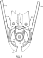
- the embodiment of FIGs. 3-9 has a clamp 4 with a pair of clamp arms 41, but it should be appreciated that a single clamp arm may be provided instead of a pair.
- the clamp arm(s) may include a feature to help properly engage the clamp arm(s) with a variety of different bottle necks.
- different bottles may have different neck diameters, different lip diameters or lengths (as used herein, a lip is a feature of many wine bottles near the top of the neck in which the bottle flares, steps or otherwise protrudes outwardly in size).
- the clamp arm(s) include a distal tab feature and a proximal ridge feature that cooperate to properly engage with different neck configurations.
- FIGs. 7-9 show one illustrative embodiment in which each clamp arm 41 includes a distal tab 43 and a proximal ridge 44.
- the tab 43 may extend radially inwardly somewhat more than the ridge 44, and thus help to center the bottle neck or otherwise appropriately position the neck relative to the clamp arms 41. For example, as the clamp arms 41 are closed on a neck, the tabs 43 may contact the neck before the ridges 44, helping to center or otherwise appropriately position the neck relative to the device 1.
- the tabs 43 and/or the ridges 44 may have portions that contact the bottle neck have a relatively hard, low-friction surface to help allow the clamp arms 41 engage the neck while allowing the neck to shift in position relative to the clamp arms 41.
- the tabs 43 may help urge the neck proximally relative to the base 2, e.g., to move the neck toward a pad 22 located on the base 2 between the clamp arms 41.
- the clamp arms 41 may help position the neck in a consistent way relative to the needle guide 202 and the needle 200. This may help ensure that the needle 200 penetrates a bottle cork in a desired location.
- the needle guide 202 and needle 200 may be arranged to pierce a cork in a location that is offset from a center of the cork with the neck positioned in contact with the pad 22. This may help avoid having the needle 200 penetrate the closure in the same location if the device 1 is used two or more times to extract beverage from the bottle.
- the needle 200 and guide 202 may be configured to penetrate a cork at its center with the neck in contact with the pad 22.
- the ridge 44 may have a length measured in a direction perpendicular to a bottle neck (or in a direction perpendicular to the length of the needle 200) that is greater than the tab 43, e.g., to help the ridge 43 provide a suitably long contact surface for the lip of the bottle.
- the tabs 43 may help center the neck between the clamp arms 41 and urge the neck to move proximally
- the ridges 43 may contact an underside of the bottle lip with a suitably long surface to help prevent the neck from moving downwardly relative to the clamp arms 41 more than a desired distance.
- the extended length of the ridges 44 may provide the ridges 44 with greater strength and help the clamp arms operate with a wide array of bottle neck and lip sizes and shapes.
- the ridges 44 may have a variable radial length, e.g., increasing proximally as shown in FIG. 7 , to help ensure that the ridges 44 will provide suitable engagement with a variety of different necks having different lip dimensions.
- the device 1 includes a detent that resiliently holds the body 3 in an upper position relative to the base 2, e.g., to help ensure that the body 3 does not move relative to the base 2 while at rest on a counter top.
- the detent may include a spring-loaded ball or other element mounted on the base 2 that engages with a suitable groove on the body 3 to hold the body 3 and base 2 stationary relative to each other until suitable force is exerted to overcome the detent holding function. (See, for example, FIG.
- a detent 23 that includes a spring loaded plunger mounted to the base 2 that is arranged to engage with a groove or other feature on the rail 31 of the body 3.
- Other detent arrangements are possible, such as a spring-loaded tab and slot, and others as will be appreciated by those of skill in the art.
- a detent is not required to releasably hold the body 3 and base 2 in one or more positions relative to each other.
- a friction element such as a rubber strip positioned between the rail 31 and channel 21
- the friction element may provide the friction force for specific body/base positions, or throughout the full range of body/base movement.
- the clamp arms 41 are pivotally mounted to the base 2 such that the distal portions 41b are normally biased to move toward each other, e.g., to clamp a bottle neck positioned between the arms 41.
- the clamp arms 41 are mounted to the base 2 via pivot pins 45 and bushings 46.
- the clamp arms 41 may be movably mounted relative to the base 2 in other ways, such as by a linkage, living hinge, a sliding engagement (such as by having a portion of a clamp arm move in a channel of the base), and others.
- one arm may be fixed to the base while the other is made movable (although in this embodiment the arms are still said to be moveable relative to each other).
- Torsion or other springs may be used to provide the biasing force (if provided at all) on the clamp arms 41.
- torsion springs 47 are mounted over the bushings 46 and are arranged to engage the base 2 and a clamp arm 41 so that the clamp arms are biased to move the distal portions 41b toward each other.
- This clamping force of the clamp arms 41 may be sufficiently robust to support the device 1 on the bottle, or even to allow a user to lift and pour beverage from the bottle by grasping and manipulating the device 1.
- the clamp arms 41 may also include proximal portions 41a that can be grasped by a user and moved together (overcoming the biasing force of the springs 47) so that the distal portions 41b are moved away from each other to receive a bottle neck.
- a user may pinch the proximal portions 41a together to position a bottle neck between the distal portions 41b, and then release the proximal portions 41a to allow the clamp arms 41 to clamp the bottle neck.
- the distal portions 41b may instead be biased to move away from each other and move toward each other when a user applies suitable force, e.g., to the distal portions 41b, to overcome the biasing force.
- the clamp arms 41 need not be spring biased at all. In such arrangements where the clamp arms 41 are biased to move the distal portions 41b apart or are not biased at all, a locking mechanism may be used to engage the clamp arms 41 to the bottle.
- a single needle with a single lumen is used to introduce gas into the bottle and extract beverage from the bottle.
- two or more needles may be used, e.g., one needle for gas delivery and one needle for beverage extraction.
- the valve 300 may operate to simultaneously open a flow of gas to the bottle and open a flow of beverage from the bottle.
- the needles may have the same or different diameters or the same or different length varying from 0.635 to 25.4 cm (0.25 to 10 inches).
- one needle delivering gas could be longer than another that extracts wine from the bottle.
- a two lumen needle may be employed where gas travels in one lumen and beverage travels in the other. Each lumen could have a separate entrance and exit, and the exits could be spaced from each other within the bottle to prevent circulation of gas.
Landscapes
- Engineering & Computer Science (AREA)
- Chemical & Material Sciences (AREA)
- Chemical Kinetics & Catalysis (AREA)
- Mechanical Engineering (AREA)
- General Engineering & Computer Science (AREA)
- Devices For Dispensing Beverages (AREA)
- Filling Or Discharging Of Gas Storage Vessels (AREA)
Applications Claiming Priority (2)
| Application Number | Priority Date | Filing Date | Title |
|---|---|---|---|
| US14/755,050 US9810375B2 (en) | 2015-06-30 | 2015-06-30 | Engagement of gas cylinder with gas dispenser |
| PCT/US2016/040261 WO2017004306A1 (en) | 2015-06-30 | 2016-06-30 | Engagement of gas cylinder with gas dispenser |
Publications (2)
| Publication Number | Publication Date |
|---|---|
| EP3317002A1 EP3317002A1 (en) | 2018-05-09 |
| EP3317002B1 true EP3317002B1 (en) | 2023-11-01 |
Family
ID=56464300
Family Applications (1)
| Application Number | Title | Priority Date | Filing Date |
|---|---|---|---|
| EP16741192.5A Active EP3317002B1 (en) | 2015-06-30 | 2016-06-30 | Engagement of gas cylinder with gas dispenser |
Country Status (7)
| Country | Link |
|---|---|
| US (1) | US9810375B2 (https=) |
| EP (1) | EP3317002B1 (https=) |
| JP (1) | JP6800898B2 (https=) |
| CN (1) | CN108025268B (https=) |
| AU (1) | AU2016287520B2 (https=) |
| CA (1) | CA2990978A1 (https=) |
| WO (1) | WO2017004306A1 (https=) |
Families Citing this family (13)
| Publication number | Priority date | Publication date | Assignee | Title |
|---|---|---|---|---|
| US11795046B2 (en) | 2015-11-25 | 2023-10-24 | Coravin, Inc. | Beverage dispenser with container engagement features |
| US11292709B2 (en) | 2017-12-29 | 2022-04-05 | Coravin, Inc. | Beverage dispenser with container engagement features |
| EP3380432B1 (en) * | 2015-11-25 | 2025-01-29 | Coravin, Inc. | Beverage extractor with controller |
| JP7224356B2 (ja) | 2018-01-05 | 2023-02-17 | コラヴァン,インコーポレイテッド | 飲料分配器及び容器ストッパ |
| KR20210022088A (ko) * | 2018-06-25 | 2021-03-02 | 코라빈, 인크. | 음료 용기를 가압하는 방법 및 용기 스토퍼를 포함하는 그 장치 |
| CN110745754B (zh) * | 2019-12-23 | 2020-03-31 | 烟台工程职业技术学院(烟台市技师学院) | 一种罐头起盖器 |
| ES3008634T3 (en) * | 2020-10-22 | 2025-03-24 | Freezio Ag | Cartridge system, beverage preparation machine, and process for manufacturing a cartridge system |
| CN112450729B (zh) * | 2020-11-30 | 2024-09-03 | 江门市伊科迈特电子科技有限公司 | 一种气泡水机 |
| CA3202325A1 (en) | 2020-12-31 | 2022-07-07 | Daniel Halbig | Auto-injector and related methods of use |
| ES3062383T3 (en) | 2021-10-01 | 2026-04-10 | Sodapop Gmbh | Receiving device for receiving a bottle on a carbonation machine; carbonation machine, and method for using a carbonation machine |
| US12005408B1 (en) | 2023-04-14 | 2024-06-11 | Sharkninja Operating Llc | Mixing funnel |
| WO2024254837A1 (en) | 2023-06-16 | 2024-12-19 | Sharkninja Operating Llc | Carbonation mixing nozzles |
| WO2025199053A1 (en) * | 2024-03-18 | 2025-09-25 | A Common Thread, Inc. | Carbonation device for enhancing a beverage |
Citations (1)
| Publication number | Priority date | Publication date | Assignee | Title |
|---|---|---|---|---|
| JP2004138104A (ja) * | 2002-10-16 | 2004-05-13 | Asahi Seisakusho Co Ltd | ガス圧力調整供給装置 |
Family Cites Families (56)
| Publication number | Priority date | Publication date | Assignee | Title |
|---|---|---|---|---|
| US1509916A (en) | 1924-09-30 | of springville | ||
| US718163A (en) | 1902-10-17 | 1903-01-13 | Joseph Alfred Sherrard | Bottle-tap. |
| GB191008433A (en) | 1910-04-07 | 1910-10-27 | Robert Hunter Campbell | Improvements in Containers, or Capsules, for Compressed, or Liquified, Gas. |
| US2367077A (en) | 1942-05-18 | 1945-01-09 | Knapp Monarch Co | Dispensing faucet |
| US2496258A (en) | 1946-03-22 | 1950-02-07 | Prel Inc | Container with closure and closure puncturing dispensing spout |
| US2705578A (en) | 1952-02-04 | 1955-04-05 | John C Burns | Carbonating type dispensing faucet |
| US2805846A (en) * | 1954-11-08 | 1957-09-10 | Dewan Leon | Device for carbonating beverages |
| US3200094A (en) | 1962-03-14 | 1965-08-10 | Nat Starch Chem Corp | Remoistenable adhesive compositions and method for making the same |
| US3191533A (en) | 1963-01-23 | 1965-06-29 | Jet Res Ct Inc | Gas discharge apparatus |
| US3272404A (en) | 1964-11-10 | 1966-09-13 | Robirds | Fluid dispenser |
| US3327899A (en) | 1965-09-13 | 1967-06-27 | Conax Corp | Beverage dispensing apparatus |
| US3542240A (en) | 1968-10-14 | 1970-11-24 | Ida Solowey | Partially assembled bulk parenteral solution container and adminstration set |
| US3883043A (en) | 1973-10-18 | 1975-05-13 | Charles Robert Lane | Dispensor for vintage wines |
| FR2257855A1 (en) | 1973-10-26 | 1975-08-08 | Mariet Jacques | Compressed gas bottle with sealing head - has joint and welded seam forming separate seals on bottle neck |
| US3976221A (en) | 1974-06-28 | 1976-08-24 | Gmf Inc. | Carbonator and dispenser for carbonated liquid or the like |
| US4011971A (en) | 1975-12-29 | 1977-03-15 | Edward R. Haydon | Device for dispensing liquids from a sealed container and for preserving undispensed portions thereof |
| JPS5357518A (en) | 1976-11-04 | 1978-05-24 | Nobuyuki Sugimura | Bladder type accumulators provided with builttin type gas bombs in their gas chambers |
| FR2507735B1 (fr) | 1981-06-12 | 1986-01-03 | Laffort Rene | Obturateur mobile permettant l'ouverture et la fermeture de recipients contenant des aerosols |
| US4473174A (en) | 1982-07-30 | 1984-09-25 | Howard John Cream | Wine preserver and dispenser |
| US4475576A (en) | 1982-09-03 | 1984-10-09 | Simon Philip E | Wine preservation system |
| DE3481207D1 (de) | 1983-12-06 | 1990-03-08 | Horst Dieter Dipl In Heinemann | Dachkonstruktion. |
| US4595121A (en) | 1984-09-10 | 1986-06-17 | Sheldon Schultz | Apparatus and method for dispensing and preserving bottled degradable liquids such as wine and the like |
| US4674662A (en) | 1985-06-11 | 1987-06-23 | Ambience, Inc. | Dispenser for bottled liquid |
| US4856680A (en) | 1985-10-09 | 1989-08-15 | Sitton Robert E | Method and apparatus for dispensing beverages |
| US4694850A (en) | 1985-10-11 | 1987-09-22 | Nippon Tansan Gas Co., Ltd. | Gas supply mechanism |
| US4706847A (en) | 1986-05-05 | 1987-11-17 | Senmar Corporation | Dispenser for wine |
| IL79877A0 (en) | 1986-08-28 | 1986-11-30 | Ehud Almog | Method for making carbonated beverages |
| US4932561A (en) | 1986-10-24 | 1990-06-12 | Boxall Stanley S | Beverage cooling and dispensing apparatus |
| US5020395A (en) | 1987-01-13 | 1991-06-04 | Mackey Edward R | Pressurized cork-removal apparatus for wine bottles and other containers |
| US5180081A (en) | 1987-09-10 | 1993-01-19 | Mccann's Engineering & Mfg. Co. | Pouring spout and carbonation retention apparatus |
| US4867209A (en) | 1987-10-29 | 1989-09-19 | United Soda, Inc. | Portable hand holdable carbonating apparatus |
| US4953741A (en) | 1988-05-09 | 1990-09-04 | Multi-Technology Inc. | Medical fail safe releasible locks and/or seals for capped disposable centrifuge containers, cryogenic vials and the like |
| JPH0738771B2 (ja) | 1989-01-17 | 1995-05-01 | 花王株式会社 | 液状食用油組成物 |
| US5031799A (en) | 1989-02-17 | 1991-07-16 | Charlie O Company, Inc. | Seltzer dispenser for use with a home soda dispensing system |
| US4984711A (en) | 1989-10-23 | 1991-01-15 | Ellis Charles V | Wine dispenser |
| US4982879A (en) | 1989-12-19 | 1991-01-08 | Apf Industries | Bottle contents dispensing and contents preservation apparatus |
| DE4009248A1 (de) | 1990-03-22 | 1991-10-02 | Knopf Karl Horst | Batterie fuer gaskapseln |
| US5139179A (en) | 1990-10-09 | 1992-08-18 | Cecil Kenneth B | Apparatus for dispensing and preserving liquids |
| US5163909A (en) | 1991-01-28 | 1992-11-17 | Alan E. Jordan | Medical fluid delivery system |
| DE4319910C2 (de) | 1992-06-17 | 2000-04-27 | Isi Metallwarenfabrik Ges M B | Wiederbefüllbare Druckgaskapsel |
| US5407096A (en) | 1992-11-30 | 1995-04-18 | Sherman Products Corporation | Apparatus for providing a portable source of high pressure gas |
| US5395012A (en) | 1993-01-19 | 1995-03-07 | Kineret Engineering | Carbonated soft drink attachment |
| DE9401917U1 (de) | 1994-02-05 | 1994-03-31 | Bernhardt Apparatebau Gmbh + Co., 22880 Wedel | Auslöseadapter für Druckgaspatrone |
| US5590696A (en) * | 1994-07-14 | 1997-01-07 | Reebok International Ltd. | Inflation system utilizing a pressurized gas inflation device and adaptor therefor |
| FR2761652B1 (fr) | 1997-04-07 | 1999-06-04 | Zefal | Dispositif de gonflage mettant en oeuvre une bouteille ou cartouche de gaz comprime |
| US6371173B1 (en) | 2000-06-22 | 2002-04-16 | Permafresh Corporation | Threaded connecting assembly |
| US6607100B2 (en) | 2001-11-26 | 2003-08-19 | Vin Valet, Inc. | Wine or champagne preservation and dispensing apparatus |
| DE50204171D1 (de) | 2002-01-23 | 2005-10-13 | Kwc Ag | Dichtung für einen Carbonisator |
| US7056179B2 (en) | 2002-05-05 | 2006-06-06 | Courtney William L | Combination inflator and manifold assembly |
| US6843388B1 (en) | 2002-07-22 | 2005-01-18 | Anthony Scott Hollars | Compressed gas cartridge dispensing system allowing interchangeable use of different capacity compressed gas cartridges and novel storage feature |
| US7712637B2 (en) | 2003-12-11 | 2010-05-11 | Gregory Lambrecht | Wine extraction and preservation device and method |
| US8413329B2 (en) | 2005-08-01 | 2013-04-09 | Illinois Tool Works Inc. | Compressed gas cartridge lance housing |
| US7703640B1 (en) | 2006-02-01 | 2010-04-27 | Anthony Scott Hollars | Heat actuated puncturing mechanism for a compressed gas cartridge |
| US8033431B2 (en) | 2007-05-07 | 2011-10-11 | Wine Gadgets, Llc | Wine preservation and dispensing apparatus |
| GB201006363D0 (en) | 2010-04-16 | 2010-06-02 | Linde Ag | Gas supply system |
| GB201304784D0 (en) * | 2013-03-15 | 2013-05-01 | Euro Celtique Sa | Dispenser |
-
2015
- 2015-06-30 US US14/755,050 patent/US9810375B2/en active Active
-
2016
- 2016-06-30 EP EP16741192.5A patent/EP3317002B1/en active Active
- 2016-06-30 WO PCT/US2016/040261 patent/WO2017004306A1/en not_active Ceased
- 2016-06-30 CN CN201680039282.3A patent/CN108025268B/zh active Active
- 2016-06-30 AU AU2016287520A patent/AU2016287520B2/en active Active
- 2016-06-30 CA CA2990978A patent/CA2990978A1/en not_active Abandoned
- 2016-06-30 JP JP2017567188A patent/JP6800898B2/ja active Active
Patent Citations (1)
| Publication number | Priority date | Publication date | Assignee | Title |
|---|---|---|---|---|
| JP2004138104A (ja) * | 2002-10-16 | 2004-05-13 | Asahi Seisakusho Co Ltd | ガス圧力調整供給装置 |
Also Published As
| Publication number | Publication date |
|---|---|
| CN108025268B (zh) | 2021-02-19 |
| EP3317002A1 (en) | 2018-05-09 |
| JP6800898B2 (ja) | 2020-12-16 |
| AU2016287520A1 (en) | 2018-01-25 |
| WO2017004306A1 (en) | 2017-01-05 |
| US20170002980A1 (en) | 2017-01-05 |
| AU2016287520B2 (en) | 2020-12-24 |
| US9810375B2 (en) | 2017-11-07 |
| CN108025268A (zh) | 2018-05-11 |
| JP2018520953A (ja) | 2018-08-02 |
| HK1254145A1 (zh) | 2019-07-12 |
| CA2990978A1 (en) | 2017-01-05 |
Similar Documents
| Publication | Publication Date | Title |
|---|---|---|
| EP3317002B1 (en) | Engagement of gas cylinder with gas dispenser | |
| AU2018202526B2 (en) | Method and apparatus for beverage extraction with improved gas cylinder access | |
| US9061877B2 (en) | Method and apparatus for beverage extraction needle guiding | |
| EP4417539A2 (en) | Beverage container stopper and pressurization system | |
| AU2018309660B2 (en) | Beverage extractor with container disengagement feature | |
| HK1254145B (zh) | 气体筒与气体分配器的接合 | |
| HK1208663A1 (en) | Device for extracting a beverage from within a container | |
| HK1208663B (en) | Device for extracting a beverage from within a container |
Legal Events
| Date | Code | Title | Description |
|---|---|---|---|
| STAA | Information on the status of an ep patent application or granted ep patent |
Free format text: STATUS: THE INTERNATIONAL PUBLICATION HAS BEEN MADE |
|
| PUAI | Public reference made under article 153(3) epc to a published international application that has entered the european phase |
Free format text: ORIGINAL CODE: 0009012 |
|
| STAA | Information on the status of an ep patent application or granted ep patent |
Free format text: STATUS: REQUEST FOR EXAMINATION WAS MADE |
|
| 17P | Request for examination filed |
Effective date: 20180117 |
|
| AK | Designated contracting states |
Kind code of ref document: A1 Designated state(s): AL AT BE BG CH CY CZ DE DK EE ES FI FR GB GR HR HU IE IS IT LI LT LU LV MC MK MT NL NO PL PT RO RS SE SI SK SM TR |
|
| AX | Request for extension of the european patent |
Extension state: BA ME |
|
| DAV | Request for validation of the european patent (deleted) | ||
| DAX | Request for extension of the european patent (deleted) | ||
| STAA | Information on the status of an ep patent application or granted ep patent |
Free format text: STATUS: EXAMINATION IS IN PROGRESS |
|
| 17Q | First examination report despatched |
Effective date: 20201002 |
|
| REG | Reference to a national code |
Ipc: B01F0023236100 Ref country code: DE Ref legal event code: R079 Ref document number: 602016083816 Country of ref document: DE Free format text: PREVIOUS MAIN CLASS: B01F0003040000 |
|
| GRAP | Despatch of communication of intention to grant a patent |
Free format text: ORIGINAL CODE: EPIDOSNIGR1 |
|
| STAA | Information on the status of an ep patent application or granted ep patent |
Free format text: STATUS: GRANT OF PATENT IS INTENDED |
|
| RIC1 | Information provided on ipc code assigned before grant |
Ipc: B67D 1/04 20060101ALI20230511BHEP Ipc: B67B 7/86 20060101ALI20230511BHEP Ipc: B01F 23/2361 20220101AFI20230511BHEP |
|
| INTG | Intention to grant announced |
Effective date: 20230531 |
|
| GRAS | Grant fee paid |
Free format text: ORIGINAL CODE: EPIDOSNIGR3 |
|
| GRAA | (expected) grant |
Free format text: ORIGINAL CODE: 0009210 |
|
| STAA | Information on the status of an ep patent application or granted ep patent |
Free format text: STATUS: THE PATENT HAS BEEN GRANTED |
|
| AK | Designated contracting states |
Kind code of ref document: B1 Designated state(s): AL AT BE BG CH CY CZ DE DK EE ES FI FR GB GR HR HU IE IS IT LI LT LU LV MC MK MT NL NO PL PT RO RS SE SI SK SM TR |
|
| REG | Reference to a national code |
Ref country code: GB Ref legal event code: FG4D |
|
| REG | Reference to a national code |
Ref country code: CH Ref legal event code: EP |
|
| REG | Reference to a national code |
Ref country code: IE Ref legal event code: FG4D |
|
| REG | Reference to a national code |
Ref country code: DE Ref legal event code: R096 Ref document number: 602016083816 Country of ref document: DE |
|
| REG | Reference to a national code |
Ref country code: LT Ref legal event code: MG9D |
|
| REG | Reference to a national code |
Ref country code: NL Ref legal event code: MP Effective date: 20231101 |
|
| PG25 | Lapsed in a contracting state [announced via postgrant information from national office to epo] |
Ref country code: GR Free format text: LAPSE BECAUSE OF FAILURE TO SUBMIT A TRANSLATION OF THE DESCRIPTION OR TO PAY THE FEE WITHIN THE PRESCRIBED TIME-LIMIT Effective date: 20240202 |
|
| PG25 | Lapsed in a contracting state [announced via postgrant information from national office to epo] |
Ref country code: IS Free format text: LAPSE BECAUSE OF FAILURE TO SUBMIT A TRANSLATION OF THE DESCRIPTION OR TO PAY THE FEE WITHIN THE PRESCRIBED TIME-LIMIT Effective date: 20240301 |
|
| PG25 | Lapsed in a contracting state [announced via postgrant information from national office to epo] |
Ref country code: LT Free format text: LAPSE BECAUSE OF FAILURE TO SUBMIT A TRANSLATION OF THE DESCRIPTION OR TO PAY THE FEE WITHIN THE PRESCRIBED TIME-LIMIT Effective date: 20231101 |
|
| REG | Reference to a national code |
Ref country code: AT Ref legal event code: MK05 Ref document number: 1626586 Country of ref document: AT Kind code of ref document: T Effective date: 20231101 |
|
| PG25 | Lapsed in a contracting state [announced via postgrant information from national office to epo] |
Ref country code: NL Free format text: LAPSE BECAUSE OF FAILURE TO SUBMIT A TRANSLATION OF THE DESCRIPTION OR TO PAY THE FEE WITHIN THE PRESCRIBED TIME-LIMIT Effective date: 20231101 |
|
| PG25 | Lapsed in a contracting state [announced via postgrant information from national office to epo] |
Ref country code: AT Free format text: LAPSE BECAUSE OF FAILURE TO SUBMIT A TRANSLATION OF THE DESCRIPTION OR TO PAY THE FEE WITHIN THE PRESCRIBED TIME-LIMIT Effective date: 20231101 |
|
| PG25 | Lapsed in a contracting state [announced via postgrant information from national office to epo] |
Ref country code: ES Free format text: LAPSE BECAUSE OF FAILURE TO SUBMIT A TRANSLATION OF THE DESCRIPTION OR TO PAY THE FEE WITHIN THE PRESCRIBED TIME-LIMIT Effective date: 20231101 |
|
| PG25 | Lapsed in a contracting state [announced via postgrant information from national office to epo] |
Ref country code: NL Free format text: LAPSE BECAUSE OF FAILURE TO SUBMIT A TRANSLATION OF THE DESCRIPTION OR TO PAY THE FEE WITHIN THE PRESCRIBED TIME-LIMIT Effective date: 20231101 Ref country code: LT Free format text: LAPSE BECAUSE OF FAILURE TO SUBMIT A TRANSLATION OF THE DESCRIPTION OR TO PAY THE FEE WITHIN THE PRESCRIBED TIME-LIMIT Effective date: 20231101 Ref country code: IS Free format text: LAPSE BECAUSE OF FAILURE TO SUBMIT A TRANSLATION OF THE DESCRIPTION OR TO PAY THE FEE WITHIN THE PRESCRIBED TIME-LIMIT Effective date: 20240301 Ref country code: GR Free format text: LAPSE BECAUSE OF FAILURE TO SUBMIT A TRANSLATION OF THE DESCRIPTION OR TO PAY THE FEE WITHIN THE PRESCRIBED TIME-LIMIT Effective date: 20240202 Ref country code: ES Free format text: LAPSE BECAUSE OF FAILURE TO SUBMIT A TRANSLATION OF THE DESCRIPTION OR TO PAY THE FEE WITHIN THE PRESCRIBED TIME-LIMIT Effective date: 20231101 Ref country code: BG Free format text: LAPSE BECAUSE OF FAILURE TO SUBMIT A TRANSLATION OF THE DESCRIPTION OR TO PAY THE FEE WITHIN THE PRESCRIBED TIME-LIMIT Effective date: 20240201 Ref country code: AT Free format text: LAPSE BECAUSE OF FAILURE TO SUBMIT A TRANSLATION OF THE DESCRIPTION OR TO PAY THE FEE WITHIN THE PRESCRIBED TIME-LIMIT Effective date: 20231101 Ref country code: PT Free format text: LAPSE BECAUSE OF FAILURE TO SUBMIT A TRANSLATION OF THE DESCRIPTION OR TO PAY THE FEE WITHIN THE PRESCRIBED TIME-LIMIT Effective date: 20240301 |
|
| PG25 | Lapsed in a contracting state [announced via postgrant information from national office to epo] |
Ref country code: SE Free format text: LAPSE BECAUSE OF FAILURE TO SUBMIT A TRANSLATION OF THE DESCRIPTION OR TO PAY THE FEE WITHIN THE PRESCRIBED TIME-LIMIT Effective date: 20231101 Ref country code: RS Free format text: LAPSE BECAUSE OF FAILURE TO SUBMIT A TRANSLATION OF THE DESCRIPTION OR TO PAY THE FEE WITHIN THE PRESCRIBED TIME-LIMIT Effective date: 20231101 Ref country code: PL Free format text: LAPSE BECAUSE OF FAILURE TO SUBMIT A TRANSLATION OF THE DESCRIPTION OR TO PAY THE FEE WITHIN THE PRESCRIBED TIME-LIMIT Effective date: 20231101 Ref country code: NO Free format text: LAPSE BECAUSE OF FAILURE TO SUBMIT A TRANSLATION OF THE DESCRIPTION OR TO PAY THE FEE WITHIN THE PRESCRIBED TIME-LIMIT Effective date: 20240201 Ref country code: LV Free format text: LAPSE BECAUSE OF FAILURE TO SUBMIT A TRANSLATION OF THE DESCRIPTION OR TO PAY THE FEE WITHIN THE PRESCRIBED TIME-LIMIT Effective date: 20231101 Ref country code: HR Free format text: LAPSE BECAUSE OF FAILURE TO SUBMIT A TRANSLATION OF THE DESCRIPTION OR TO PAY THE FEE WITHIN THE PRESCRIBED TIME-LIMIT Effective date: 20231101 |
|
| PG25 | Lapsed in a contracting state [announced via postgrant information from national office to epo] |
Ref country code: DK Free format text: LAPSE BECAUSE OF FAILURE TO SUBMIT A TRANSLATION OF THE DESCRIPTION OR TO PAY THE FEE WITHIN THE PRESCRIBED TIME-LIMIT Effective date: 20231101 |
|
| PG25 | Lapsed in a contracting state [announced via postgrant information from national office to epo] |
Ref country code: CZ Free format text: LAPSE BECAUSE OF FAILURE TO SUBMIT A TRANSLATION OF THE DESCRIPTION OR TO PAY THE FEE WITHIN THE PRESCRIBED TIME-LIMIT Effective date: 20231101 |
|
| PG25 | Lapsed in a contracting state [announced via postgrant information from national office to epo] |
Ref country code: SK Free format text: LAPSE BECAUSE OF FAILURE TO SUBMIT A TRANSLATION OF THE DESCRIPTION OR TO PAY THE FEE WITHIN THE PRESCRIBED TIME-LIMIT Effective date: 20231101 |
|
| PG25 | Lapsed in a contracting state [announced via postgrant information from national office to epo] |
Ref country code: SM Free format text: LAPSE BECAUSE OF FAILURE TO SUBMIT A TRANSLATION OF THE DESCRIPTION OR TO PAY THE FEE WITHIN THE PRESCRIBED TIME-LIMIT Effective date: 20231101 Ref country code: SK Free format text: LAPSE BECAUSE OF FAILURE TO SUBMIT A TRANSLATION OF THE DESCRIPTION OR TO PAY THE FEE WITHIN THE PRESCRIBED TIME-LIMIT Effective date: 20231101 Ref country code: RO Free format text: LAPSE BECAUSE OF FAILURE TO SUBMIT A TRANSLATION OF THE DESCRIPTION OR TO PAY THE FEE WITHIN THE PRESCRIBED TIME-LIMIT Effective date: 20231101 Ref country code: IT Free format text: LAPSE BECAUSE OF FAILURE TO SUBMIT A TRANSLATION OF THE DESCRIPTION OR TO PAY THE FEE WITHIN THE PRESCRIBED TIME-LIMIT Effective date: 20231101 Ref country code: EE Free format text: LAPSE BECAUSE OF FAILURE TO SUBMIT A TRANSLATION OF THE DESCRIPTION OR TO PAY THE FEE WITHIN THE PRESCRIBED TIME-LIMIT Effective date: 20231101 Ref country code: DK Free format text: LAPSE BECAUSE OF FAILURE TO SUBMIT A TRANSLATION OF THE DESCRIPTION OR TO PAY THE FEE WITHIN THE PRESCRIBED TIME-LIMIT Effective date: 20231101 Ref country code: CZ Free format text: LAPSE BECAUSE OF FAILURE TO SUBMIT A TRANSLATION OF THE DESCRIPTION OR TO PAY THE FEE WITHIN THE PRESCRIBED TIME-LIMIT Effective date: 20231101 |
|
| REG | Reference to a national code |
Ref country code: DE Ref legal event code: R097 Ref document number: 602016083816 Country of ref document: DE |
|
| PLBE | No opposition filed within time limit |
Free format text: ORIGINAL CODE: 0009261 |
|
| STAA | Information on the status of an ep patent application or granted ep patent |
Free format text: STATUS: NO OPPOSITION FILED WITHIN TIME LIMIT |
|
| 26N | No opposition filed |
Effective date: 20240802 |
|
| PG25 | Lapsed in a contracting state [announced via postgrant information from national office to epo] |
Ref country code: SI Free format text: LAPSE BECAUSE OF FAILURE TO SUBMIT A TRANSLATION OF THE DESCRIPTION OR TO PAY THE FEE WITHIN THE PRESCRIBED TIME-LIMIT Effective date: 20231101 |
|
| PG25 | Lapsed in a contracting state [announced via postgrant information from national office to epo] |
Ref country code: SI Free format text: LAPSE BECAUSE OF FAILURE TO SUBMIT A TRANSLATION OF THE DESCRIPTION OR TO PAY THE FEE WITHIN THE PRESCRIBED TIME-LIMIT Effective date: 20231101 |
|
| PG25 | Lapsed in a contracting state [announced via postgrant information from national office to epo] |
Ref country code: MC Free format text: LAPSE BECAUSE OF FAILURE TO SUBMIT A TRANSLATION OF THE DESCRIPTION OR TO PAY THE FEE WITHIN THE PRESCRIBED TIME-LIMIT Effective date: 20231101 |
|
| PG25 | Lapsed in a contracting state [announced via postgrant information from national office to epo] |
Ref country code: LU Free format text: LAPSE BECAUSE OF NON-PAYMENT OF DUE FEES Effective date: 20240630 |
|
| PG25 | Lapsed in a contracting state [announced via postgrant information from national office to epo] |
Ref country code: IE Free format text: LAPSE BECAUSE OF NON-PAYMENT OF DUE FEES Effective date: 20240630 |
|
| PG25 | Lapsed in a contracting state [announced via postgrant information from national office to epo] |
Ref country code: BE Free format text: LAPSE BECAUSE OF NON-PAYMENT OF DUE FEES Effective date: 20240630 |
|
| REG | Reference to a national code |
Ref country code: BE Ref legal event code: MM Effective date: 20240630 |
|
| PGFP | Annual fee paid to national office [announced via postgrant information from national office to epo] |
Ref country code: DE Payment date: 20250627 Year of fee payment: 10 |
|
| PGFP | Annual fee paid to national office [announced via postgrant information from national office to epo] |
Ref country code: GB Payment date: 20250627 Year of fee payment: 10 |
|
| PGFP | Annual fee paid to national office [announced via postgrant information from national office to epo] |
Ref country code: FR Payment date: 20250625 Year of fee payment: 10 |
|
| PG25 | Lapsed in a contracting state [announced via postgrant information from national office to epo] |
Ref country code: FI Free format text: LAPSE BECAUSE OF FAILURE TO SUBMIT A TRANSLATION OF THE DESCRIPTION OR TO PAY THE FEE WITHIN THE PRESCRIBED TIME-LIMIT Effective date: 20231101 |
|
| PGFP | Annual fee paid to national office [announced via postgrant information from national office to epo] |
Ref country code: CH Payment date: 20250701 Year of fee payment: 10 |
|
| PG25 | Lapsed in a contracting state [announced via postgrant information from national office to epo] |
Ref country code: CY Free format text: LAPSE BECAUSE OF FAILURE TO SUBMIT A TRANSLATION OF THE DESCRIPTION OR TO PAY THE FEE WITHIN THE PRESCRIBED TIME-LIMIT; INVALID AB INITIO Effective date: 20160630 |
|
| PG25 | Lapsed in a contracting state [announced via postgrant information from national office to epo] |
Ref country code: HU Free format text: LAPSE BECAUSE OF FAILURE TO SUBMIT A TRANSLATION OF THE DESCRIPTION OR TO PAY THE FEE WITHIN THE PRESCRIBED TIME-LIMIT; INVALID AB INITIO Effective date: 20160630 |