EP3316668B1 - Gehäuseeinheit - Google Patents
Gehäuseeinheit Download PDFInfo
- Publication number
- EP3316668B1 EP3316668B1 EP16196038.0A EP16196038A EP3316668B1 EP 3316668 B1 EP3316668 B1 EP 3316668B1 EP 16196038 A EP16196038 A EP 16196038A EP 3316668 B1 EP3316668 B1 EP 3316668B1
- Authority
- EP
- European Patent Office
- Prior art keywords
- housing
- wall
- tab
- region
- connector
- Prior art date
- Legal status (The legal status is an assumption and is not a legal conclusion. Google has not performed a legal analysis and makes no representation as to the accuracy of the status listed.)
- Active
Links
Images


Classifications
-
- H—ELECTRICITY
- H05—ELECTRIC TECHNIQUES NOT OTHERWISE PROVIDED FOR
- H05K—PRINTED CIRCUITS; CASINGS OR CONSTRUCTIONAL DETAILS OF ELECTRIC APPARATUS; MANUFACTURE OF ASSEMBLAGES OF ELECTRICAL COMPONENTS
- H05K5/00—Casings, cabinets or drawers for electric apparatus
- H05K5/0026—Casings, cabinets or drawers for electric apparatus provided with connectors and printed circuit boards [PCB], e.g. automotive electronic control units
- H05K5/0069—Casings, cabinets or drawers for electric apparatus provided with connectors and printed circuit boards [PCB], e.g. automotive electronic control units having connector relating features for connecting the connector pins with the PCB or for mounting the connector body with the housing
-
- H—ELECTRICITY
- H01—ELECTRIC ELEMENTS
- H01R—ELECTRICALLY-CONDUCTIVE CONNECTIONS; STRUCTURAL ASSOCIATIONS OF A PLURALITY OF MUTUALLY-INSULATED ELECTRICAL CONNECTING ELEMENTS; COUPLING DEVICES; CURRENT COLLECTORS
- H01R13/00—Details of coupling devices of the kinds covered by groups H01R12/70 or H01R24/00 - H01R33/00
- H01R13/62—Means for facilitating engagement or disengagement of coupling parts or for holding them in engagement
- H01R13/639—Additional means for holding or locking coupling parts together, after engagement, e.g. separate keylock, retainer strap
- H01R13/6395—Additional means for holding or locking coupling parts together, after engagement, e.g. separate keylock, retainer strap for wall or panel outlets
-
- H—ELECTRICITY
- H01—ELECTRIC ELEMENTS
- H01R—ELECTRICALLY-CONDUCTIVE CONNECTIONS; STRUCTURAL ASSOCIATIONS OF A PLURALITY OF MUTUALLY-INSULATED ELECTRICAL CONNECTING ELEMENTS; COUPLING DEVICES; CURRENT COLLECTORS
- H01R13/00—Details of coupling devices of the kinds covered by groups H01R12/70 or H01R24/00 - H01R33/00
- H01R13/73—Means for mounting coupling parts to apparatus or structures, e.g. to a wall
- H01R13/74—Means for mounting coupling parts in openings of a panel
- H01R13/741—Means for mounting coupling parts in openings of a panel using snap fastening means
- H01R13/743—Means for mounting coupling parts in openings of a panel using snap fastening means integral with the housing
-
- H—ELECTRICITY
- H01—ELECTRIC ELEMENTS
- H01R—ELECTRICALLY-CONDUCTIVE CONNECTIONS; STRUCTURAL ASSOCIATIONS OF A PLURALITY OF MUTUALLY-INSULATED ELECTRICAL CONNECTING ELEMENTS; COUPLING DEVICES; CURRENT COLLECTORS
- H01R13/00—Details of coupling devices of the kinds covered by groups H01R12/70 or H01R24/00 - H01R33/00
- H01R13/73—Means for mounting coupling parts to apparatus or structures, e.g. to a wall
- H01R13/74—Means for mounting coupling parts in openings of a panel
- H01R13/741—Means for mounting coupling parts in openings of a panel using snap fastening means
- H01R13/745—Means for mounting coupling parts in openings of a panel using snap fastening means separate from the housing
Definitions
- This invention relates to a housing unit, and in particular concerns a housing unit for electronic components within a vehicle.
- Modern motor vehicles include several electronic components that need to be held within respective housings. Examples include the main processor or electronic control unit (ECU), and also sensors such as radar sensors.
- ECU electronice control unit
- sensors such as radar sensors.
- US 6,657,869 discloses a housing, particularly for use for an airbag control device, which includes a metal body having top, bottom, rear and side walls.
- the body has an open front which engages with a plastic terminating element, which includes electrical connections.
- the terminating element engages with the body through detents which cooperate with connection apertures formed in the side walls of the body.
- US2009/0042439 discloses a computer enclosure including a chassis and a connector.
- the chassis includes a bottom panel and a side panel perpendicular to the bottom panel.
- the side panel defines an opening.
- a positioning flange protrudes from the side panel parallel to the bottom panel.
- Two resilient hooks extend from the side panel at opposite sides of the opening.
- the connector is mounted in the opening.
- the connector includes a first face, a second face parallel to the first face and a top wall perpendicular to the first and second faces. Two ends of the first face are engaged with the corresponding resilient hooks.
- the second face abuts against the side panel.
- the positioning flange abuts against the top wall of the connector, thereby the connector is sandwiched between the positioning flange and the bottom panel.
- US4124267 discloses a mounting clip which is adapted to mount an electrical connector or the like in a cutout in a mounting panel.
- the clips are mounted in place on the panel in pairs and securely engage end portions of a clip by a simple "snap" action without the need for tools or securing means such as screws or the like.
- the connector is readily disengaged from one of the clips by a simple clip-bending step effected by a tool such as a screwdriver, pen knife or the like, so as to free one connector end, whereafter the opposed connector end may be readily slid from engagement with the remaining clip without damaging the connector or the clips whereby they may be reused indefinitely.
- one aspect of the present invention provides a housing suitable for containing one or more electronic components, the housing having a connection aperture formed in a wall thereof to allow connection of a cable to the wall, wherein the connection aperture is provided with a pair of tabs positioned on opposing sides thereof, the tabs being configured to hold firmly in place a connector which is inserted into the connection aperture, each tab being generally elongate and having a free end, each tab being cut out from the wall of the housing, and attached to the wall of the housing at an attachment region, each tab being deflected with respect to the wall and extending inwardly into the interior of the housing at an angle to the plane of the wall, so the free end of each tab lies within the housing, and wherein each tab has a first region, which is near or adjacent the wall, which extends at a first angle with respect to the plane of the wall, and a second region, which is further from the wall that the first region, which extends at a second angle with respect to the plane of the wall, the second angle being less than the
- connection aperture has an inward-facing lip on at least one side thereof, and a part of a connection element is received within a gap between the lip and a wall of the housing to retain the connection aperture in place.
- the part of the connection aperture comprises an upstanding wall or skirt.
- connection aperture is clamped or received in an interference fit between the lip and a wall of the housing.
- the first region extends at an angle of around 90° with respect to the plane of the wall, and the second region extends, at its free end, in a direction which has a component pointing towards the other of the tabs.
- each tab has a shape which includes a pair of substantially parallel tongues extending away from the attachment region, there being a cut out region between the tongues.
- the housing defines a generally substantially enclosed interior, aside from the connection aperture.
- each tab is at least 80% of the height of the connection aperture, and is preferably at least 90% of the height of the connection aperture.
- the connector further comprises an outwardly-extending flange region, the flange region being spaced from the rearwardly-facing shoulders such that, when the connector is inserted into the connection aperture, when the free end of the tabs rest against the respective rearwardly-facing shoulders of the connector, a front surface of the flange portion lies against or adjacent an outer surface of the wall of the housing.
- a further aspect of the present invention provides a method of forming a connection aperture in a wall of a housing, comprising the steps of: forming one or more cuts in a wall of the housing to form a pair of tabs, each tab being generally elongate and being attached to the housing at an attachment region, and having a free end; and deflecting each tab at or near the attachment region with respect to the wall so that each tab extends inwardly into the interior of the housing at an angle to the plane of the wall, so the free end of each tab lies within the housing, and wherein each tab has a first region, which is near or adjacent the attachment region, which extends at a first angle with respect to the plane of the wall, and a second region, which is further from the attachment region that the first region, which extends at a second angle with respect to the plane of the wall, the second angle being less than the first angle, wherein the tabs are configured to hold firmly in place a connector which is inserted into the connection aperture.
- the step of deflecting each tab includes the step of deflecting each tab so that the first region extends at an angle of around 90° with respect to the plane of the wall, and the second region extends at its free end, in a direction which has a component point pointing towards the other of the tabs.
- the step of forming cuts in the wall of the housing to form a pair of tabs comprises forming cuts so that each tab has a shape which includes a pair of substantially parallel tongues extending away from the attachment region, there being a cut-out region between the tongues.
- connection aperture is formed in the wall of a housing which defines a generally substantially enclosed interior, aside from the connection aperture.
- the step of forming cuts in the wall of the housing to form a pair of tabs comprises forming cuts such that the height of each tab is at least 80% of the height of the connection aperture, and is preferably at least 90% of the height of connection aperture.
- Embodiments of the invention involve a main body, which is formed from a robust material such as metal.
- the main body may, for example, be formed from steel, aluminium or another suitable material.
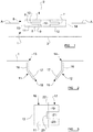
- a side wall 1 of a main body is shown, during production of a finished housing embodying the present inventories.
- the side wall 1 extends between a top wall 2 and bottom wall 3, as will be described in more detail below.
- First and second cuts 4, 5 are formed through the thickness of the side wall 1.
- the first and second cuts 4, 5 are preferably straight and parallel with one another.
- the first and second cuts 4, 5 are also preferably of the same or substantially the same length, and are aligned with each other.
- the length of each of the first and second cuts 4, 5 may be around 13-15mm, in one example, but the invention is not limited to this.
- Two bridging cuts 6, 7 extend between the first and second cuts 4, 5.
- a first bridging cut 6, 7 is closer to a first end 8 of the first and second cuts 4, 5.
- the first bridging cut 6 extends generally directly between the first and second cuts 4, 5 but includes a generally rectangular tongue 9 which extends toward, but does not reach, the first end 8.
- the tongue 9 is defined by regions of the first bridging cut 6 that extend generally parallel to the first and second cuts 4, 5.
- the tongue 9 has a generally straight end portion 10, which is preferably substantially perpendicular to the first and second cuts 4, 5.
- the second bridging cut 7 is closer to a second, opposite end of the first and second cuts 4, 5, and preferably generally takes the form of a mirror-image of the first bridging cut 6.
- the two bridging cuts 6, 7 are preferably symmetrically arranged with respect to a line that passes through the centres of the first and second cuts 4, 5, perpendicular thereto.
- FIG. 1 there is a generally cross-shaped region 10 defined between the first and second cuts 4, 5 and the first and second bridging cuts 6, 7, that will become entirely detached from the side wall 1 and will be removed.
- the cuts 4, 5, 6, 7 also create first and second tabs 11, 12. These tabs will, as is explained in more detail below, be bent inwardly with respect to the side wall 1 along hinge regions 13, 14, which are indicated by dotted lines in figure 1 .
- the hinge regions 13, 14 generally extend between the ends of the first cuts 4, 5, substantially perpendicular thereto.
- each tab 11, 12 substantially fully occupies the height of the connection aperture 15.
- each tab 11, 12 has a height which is at least 80% of the height of the connection aperture 15, and yet more preferably has a height which is at least 90% of the height of the connection aperture 15.
- FIG 2 shows a schematic cutaway view of the side wall 1, taken through the line indicated by A-A in figure 1 .
- the first and second tabs 11, 12 have been bent inwardly along the hinge regions 13, 14, and it will be appreciated that this forms a connection aperture 15 through the side wall 1.
- the tabs 11, 12 are bent relatively sharply at the hinged regions 13, 14.
- the bends formed at the hinged regions 13, 14 may alternatively be more gradual, radiused bends.
- Each tab has a first portion 16, which is adjacent to the appropriate hinged region 13, 14 and preferably extends in a direction which is perpendicular or substantially perpendicular to the plane of the side wall 1.
- Each tab 11, 12 also has a second portion 17, furthest from the hinge regions 13, 14, which is angled inwardly with respect to the first region 16.
- the second portion 17 of each tab 11, 12 is set an angle of approximately 15° relatively to a plane which is perpendicular to the plane of the side wall 1.
- the second portion 17 of each tab 11 is preferably set at an angle of 75° to the plane of the side wall 1.
- first and second portions 16, 17 of each tab 11, 12 each occupy around half of the length of the tab 11, 12. In other embodiments one of the first and second portions 16, 17 may be longer than the other, although it is preferred that neither of the first and second portions 16, 17 is less than around a third of the length of the tab 11, 12.
- Each of the second portions 17 terminates in a respective free end 18.
- Figure 3 shows a schematic view of the first tab 11, bent inwardly around the hinge region 13.
- the first tab 11 has a generally forked shape, having first and second protruding tongues, 19, 20, which are preferably generally rectangular in shape.
- Overall the first tab 11 is generally "C"-shaped.
- a bend 22 is formed in the first tab 11 between the first portion 16 and second portion 17 thereof.
- the bend 22 is formed at a distance from the hinge 13 such that the bend is formed only in the first and second tongues 19, 20.
- the bend 22 is formed further from the hinge region 13 than the inner end 23 of the cut-out section 21.
- bend 22 could be formed closer to the hinge region 13 than the inner end 23 of the cut out section 21.
- Figure 4 shows a connector 24 which is adapted to be connected to the connection aperture 15 formed as described above.
- the connector 24 comprises a generally elongate main body 25, having electrically conducting connectors 26 running therethrough.
- the connector 24 has a generally transverse flange portion 27 part-way along its length, which protrudes from both sides of the main body 25. In operation, a front surface 28 the flange portion 27 will abut against the outer surface of the side wall 1 of the main body.
- the connector 24 includes an engagement portion 29, which protrudes forwardly from the flange portion 27 and which, in use, is intended to lie within the main body, i.e. on the interior side of side wall 1.
- An initial portion 30 of the engagement portion 29 includes generally straight, parallel outer side walls, which are generally parallel with a longitudinal axis of the connector 24.
- connection portion 29 terminates in a third, widened portion 32.
- a pair of rearward-facing shoulders 34 are formed, one on each side of the connector 24.
- an inner portion 35 of the shoulder is set at a relatively steep angle (in the example shown, around 45°) to the longitudinal axis of the connector 24.
- An outer portion 36 of the shoulder 34 is set to be perpendicular or almost perpendicular to the longitudinal axis of the connector.
- the angle of the outer portion 36 of the shoulder 34 generally matches the angle at which the second portion 17 of each tab 11, 12 is set to the side wall 1. Therefore, in this example, the outer section 36 of the shoulder 34 is set at around 75° to the longitudinal axis of the connector 24.
- the third, widened portion 32 has side walls 37 which are generally straight and parallel with the longitudinal axis of the connector 24, although at its forward-most portion the side wall 37 terminates in an inwardly-tapered portion 38.
- the engagement portion 29 terminates in a generally flat end wall 39, which is perpendicular or substantially perpendicular to the longitudinal axis to the connector 24.
- the widths of the third, widened portion 32, and of the first portion 30, of the engagement portion 29 are approximately the same as, or slightly less than, the width of the connection aperture 15.
- connection portion 29 As the forward-most part of the engagement portion 29 is inserted into the connection aperture 15, the third, widened portion 32 passes through the connection aperture 15, and contact the inwardly-deflected second portions 17 of the tabs 11, 12.
- the tabs 11, 12 are deflected outwardly as the connection portion 29 is introduced, and this is assisted by the tapered portions 38 formed near the end of the connection portion 29.
- connection portion 29 Once the third, widened portion 32 of the connection portion 29 has been pushed all the way past the free ends 18 of the tabs 11, 12, the tabs 11, 12 spring back inwardly, so the free ends 18 thereof rest on the rearward-facing shoulders 34 formed between the second and third portions 31, 32 of the connection portion 29.
- the front surface 28 of the flange portion 27 is abutted against the outer surface of the side wall 1. It will therefore be understood that the distance from the front surface 28 of the flange portion 27 to the rearward-facing shoulders 34 is approximately the same as, or slightly greater than, the distance from the outer surface of the side wall 1 and the free end 18 of each tab 11, 12.
- FIG. 5 This arrangement is shown in figure 5 .
- the side walls of the first portion 30 of the connection portion 29 lie against the inner surfaces of the first portion 16 of each tab 11, 12, thereby providing robust resistance to any lateral movement of the connector 24 with respect to the side wall 1.
- the height of the first portion 30 of the connector 24 also matches closely the height of the connection aperture 15, and so motion of the connector 24 with respect to the side wall 1 in a direction generally parallel with the side wall 1 but perpendicular to the width of the connection aperture 15 will also be strongly resisted.
- the third, widened portion 32 of the connector portion 29 has spaced apart first and second layers 33, 34, each of which has the external shape shown in figure 4 , having first, second and third portions 30, 31, 32.
- a space is defined between the first and second layers 33, 34.
- each of tongues 19, 20 of each of the tabs 11, 12 may rest against the rearwardly-facing shoulder 34 of the respective first and second layers 40, 41.
- the PCB 42 is (in this example) generally rectangular in shape, and has a series of sliding connectors 43 formed on one side thereof.
- the first and second layers 40, 41 are spaced apart by a suitable distance so that the PCB 42 can fit between the layers.
- the PCB 42 fits snugly between the layers 40, 41 so that, where it is held by the layers 40, 41, it cannot substantially move or vibrate in a direction perpendicular to the plane of the PCB 42.
- the layers 40, 41 may have features which cooperate with the sliding connectors 43 of the PCB 42, to help hold the PCB 42 in place with respect to the connector 24.
- the connector 24 will provide a power and/or data connection between the PCB 42 and the exterior of the main body.
- the electrically conducting connectors 26 which run through the connector 24 contact electrical connectors on the PCB 42 for this purpose.
- the electrical connectors on the PCB 42 are preferably formed as part of the sliding connectors 43.
- the PCB 42 is firmly mounted within the main body such that, when the connector 24 is connected to the main body in the manner described above, the connector 24 cooperates and connects with the PCB 42. This allows for a simple and robust connection (without any intermediate connectors between the connector 24 and the PCB 42 being needed), and also allows an efficient use of space within the main body.
- the separated first and second levels 40, 41 of the connector 24, along with the forked shape of the tabs 11, 12, allow this connection between the connector 24 and the PCB 42, as the edge of the PCB 42 can fit between the layers 40, 41 and between the tongues 19, 20 of the forked shape of each tab 11, 12.
- the tabs may have a shape which is rectangular or substantially rectangular, without the forked design shown in figures 3 and 5 .
- the connection portion of the connector may not involve the design shown in figure 6 , involving first and second separated layers 40, 41.
- the side wall 1 may form part of a housing, which defines a generally enclosed space in which one or more electronic components may be provided.
- the housing may, in some embodiments, comprise a metal component which provides a substantially enclosed space aside from one open surface, for instance providing top, bottom, side and rear walls, but no front wall.
- a plastic retaining wall may be attached to the open end of the housing, using any suitable means to provide an entirely or substantially enclosed space within the housing.
- a construction of this type may be suitable for a radar sensor, where the plastic side of the housing allows the radar signal to pass through.
- the housing may be formed entirely from metal walls to form an entirely or substantially enclosed space.
- the housing may take any suitable form, and need not have any particular (such as oblong) shape.
- connection aperture 15 is formed in one of the metal walls of the housing, as described above. While the formation of the connection aperture 15 above is particularly described in relation to a side wall, this is not necessarily the case and the connection aperture may be formed in any appropriate surface of the housing. In some examples the wall of the housing in which the connection aperture 15 is formed is entirely or partially curved, and references to the plane of the wall in which the connection aperture is formed should be interpreted as references to the plane of the wall at the point where the connection aperture is formed.
- connection aperture 15 Once the connection aperture 15 has been formed, a connector 24 may then be inserted into the connection aperture 15 so that it is firmly held in place, as discussed above.
- the electronic components held within the housing may then communicate with the exterior of the housing through electrical connectors (such as the electrical connectors 27 shown in figures 4 and 5 ).
- connection aperture of this type provides several advantages. Firstly, the formation of the tabs 11, 12, using punched-out sections of the metal wall of the housing is a cheap, simple and robust method of forming connection means on the housing that will cooperate with a connector to hold the connector in place.
- connection itself is also effective. Once inserted in place as shown in figure 5 , the connector 24 may not move laterally with respect to the side wall 1, either in the left-right or up-down direction, as surfaces of the connector 24 are abutted against inward-facing surfaces of the connection aperture 15. Moreover, the connector 24 may not be removed directly outwardly from the housing, because the free ends 18 of the tabs 11, 12 are abutted firmly against the inward-facing shoulders 34 of the connection member 29.
- Figure 7 , 8 and 9 show as alternative connection element 43, not part of the present invention.
- connection element 43 comprises a baseplate 44 which is, in the example shown, generally planar and rectangular.
- baseplate 44 which is, in the example shown, generally planar and rectangular.
- side portions 47, 48 are bent upwardly so they are substantially perpendicular with respect to the plane of the baseplate 44.
- the side portions 47, 48 are shaped and configured in the same way as, or a similar way to, the tabs 11, 12 of the sidewall 1, as described above.
- Each side portion 47, 48 therefore has a first generally flat portion 49 which is arranged to be perpendicular or substantially perpendicular to the plane of the baseplate 44.
- Each side portion 47, 48 further has a second portion 50, which is deflected inwardly, away from the plane of the first portion 49, towards the other of the side portions 47, 48.
- Each of the first, generally flat portions 49 has an edge, furthest from the respective second portion 50, which is preferably aligned or substantially aligned with a front edge 59 of the baseplate 44, which extends between the first and second opposing ends 45, 46 thereof.
- Each second portion 50 is also shaped to be in a "forked" configuration as is the case for the tabs 11, 12 described above.
- each of the forked portions is turned back on itself, by being bent outwardly (i.e. away from the other one of the side portions 47, 48).
- each of the forked portions is curved through 180°, and terminates in a short end portion 52 which lies parallel or substantially parallel with the main part of the forked portion.
- short, upstanding skirts 53 are provided at the first and second ends 45, 46 of the base plate 44, and also on the front edge 59 thereof.
- connection element 43 is formed from a single sheet of a robust material such as steel.
- the sheet is initially planar and is cut, stamped or otherwise formed into the correct shape, and then bent into the configuration shown in figure 7 .
- pieces of the sheet to the sides of the baseplate 44 are bent to form the first and second tabs 47, 48, and also to form the skirts 53 that are formed at the first and second ends, 45, 46 and front edge 59 of the baseplate 44.
- Figures 8 and 9 show views of the connection element 43 in use with a housing 54, which has a wall 55 with a connection aperture 56 formed therethrough.
- An inward-facing lip 57 is, in this embodiment, formed all of the way around the aperture 56.
- the connection element 43 is placed around the aperture 56 so that the baseplate 44 thereof lies on a bottom surface 58 of the housing, and the tabs 47, 48 are positioned on either side of the aperture 56.
- the inward-facing lip 57 curves inwardly so that, at its free end, it lies parallel or substantially parallel with the bottom surface 58 of the housing.
- the free end of the inward-facing lip 57 preferably comprises a short, generally straight holding section 60.
- connection element 43 has a short, upstanding skirt 53 are provided on its front edge 59.
- the height of the skirt 53 at the front edge 59 of the connection element 43 is substantially the same as, or slightly greater than, the distance between the bottom surface 58 of the housing and the free end of the inward-facing lip 57.
- the skirt 53 at the front edge 59 of the connection element 43 is positioned between the bottom surface 58 of the housing and the free end of the inward-facing lip 57, so that it is clamped or otherwise held firmly between the bottom surface 58 of the housing and the free end of the inward-facing lip 57.
- connection element 43 in place with respect to the housing, the skirt 53 will be held in place sufficiently firmly to resist movement of the connection element 43 in a direction parallel with the bottom surface 58 of the housing when a connector is inserted into the connection aperture 56.
- Rotational motion of the connection element 43 about its front edge 59 will also be strongly resisted as a result of the baseplate 44 of the connection element 43 lying against the bottom surface 58 of the housing.
- the skirt is clamped between the lip and the bottom wall of the housing.
- the skirt may be clamped between a suitable lip and another wall of the housing, for instance a side wall or top wall.
- the connection element may have two or more skirts which are clamped against respective different walls of the housing by suitable lips surrounding the connection aperture.
- connection element may be rigidly connected to the interior of the main body, for instance by welding.
- baseplate 44 may be connected to the bottom surface 58 of the main body 54.
- the tabs 47, 48 interact with the connector 24 in the same manner as the tabs 11, 12 described above in relation to the first embodiment.
- connection element 43 may be useful in situations where it is desired for the tabs to be formed of a material that is more flexible than the material that forms the main body.
- the main body may need to be very strong and robust, and to be able to withstand heavy wear and sharp impacts.
- the material from which the walls of the main unit are formed may therefore necessarily be very strong and rigid. In this case, having tabs which are stamped out of the material of the wall itself may be inappropriate, because these tabs will not be sufficiently flexible.
- the main unit may be formed from steel (or another suitable material) having a high ductility, to allow the main unit to be formed using a deep-drawing or similar process.
- steel of this kind may not be ideal for forming the tabs, and it may be preferable to form the tabs from spring steel, or another material having a high yield strength. Therefore, the provision of a separate connection element allows these parts of the housing to be formed from different materials which are each well-suited to their respective purposes.
- connection element 43 The presence of the baseplate 44 in the connection element 43 allows the connection element 43 to be firmly and reliably connected to the interior of the main body.
- each first, generally flat portions 49 of each side portion 47, 48 may, when the connection element 43 is installed, be against or close to the interior of the wall 55 of the main body, to the side of the connection aperture 56.
- the side portions 47, 48 will therefore be strongly braced to resist withdrawal of the connector 24 from the connection aperture 56.
- connection element 43 that has both side portions 47, 48 attached thereto
- two separate connection elements could be provided, with each connection element being separately attached to the interior of the main body, and having one side portion attached thereto.
- having only a single connection portion is preferred, as this is expected to be more robust and allow for a more simple overall construction.
Landscapes
- Engineering & Computer Science (AREA)
- Microelectronics & Electronic Packaging (AREA)
- Connector Housings Or Holding Contact Members (AREA)
Claims (12)
- Gehäuse, das zur Aufnahme von einer oder mehreren elektronischen Komponenten geeignet ist, wobei das Gehäuse eine Anschlussöffnung (15) hat, die in einer Wand (1) davon ausgebildet ist, um den Anschluss eines Kabels an der Wand (1) zu ermöglichen, wobei die Anschlussöffnung (15) ein Paar Laschen (11, 12) aufweist, die auf gegenüberliegenden Seiten davon positioniert sind, wobei die Laschen (11, 12) so konfiguriert sind, dass sie einen in die Anschlussöffnung (15) eingesteckten Stecker (24) fest an Ort und Stelle halten, wobei jede Lasche (11, 12) allgemein länglich ist und ein freies Ende (18) hat, dadurch gekennzeichnet, dass jede Lasche (11, 12) aus der Wand (1) des Gehäuses ausgeschnitten und an der Wand (1) des Gehäuses in einer Befestigungsregion (13, 14) befestigt ist, wobei jede Lasche (11, 12) mit Bezug auf die Wand (1) abgelenkt ist und sich nach innen in das Innere des Gehäuses in einem Winkel zur Ebene der Wand (1) erstreckt, so dass das freie Ende (18) jeder Lasche (11, 12) innerhalb des Gehäuses liegt, und wobei jede Lasche (11, 12) eine erste Region (16) in der Nähe oder neben der Wand (1) hat, die sich in einem ersten Winkel mit Bezug auf die Ebene der Wand (1) erstreckt, und eine zweite Region (17) weiter von der Wand (1) entfernt als die erste Region (16) hat, die sich in einem zweiten Winkel mit Bezug auf die Ebene der Wand (1) erstreckt, wobei der zweite Winkel kleiner als der erste Winkel ist
- Gehäuse nach Anspruch 1, wobei sich die erste Region (16) in einem Winkel von etwa 90° mit Bezug auf die Ebene der Wand (1) erstreckt und die zweite Region (17) sich an ihrem freien Ende (18) in eine Richtung mit einer Komponente erstreckt, die in Richtung der anderen der Laschen (11, 12) zeigt.
- Gehäuse nach Anspruch 1 oder 2, wobei jede Lasche (11, 12) eine Gestalt hat, die ein Paar im Wesentlichen parallele Zungen (19, 20) beinhaltet, die sich von der Befestigungsregion (13, 14) weg erstrecken, wobei zwischen den Zungen (19, 20) eine Ausschnittregion (21) vorhanden ist.
- Gehäuse nach einem vorherigen Anspruch, wobei das Gehäuse ein allgemein im Wesentlichen geschlossenes Inneres definiert, abgesehen von der Anschlussöffnung (15).
- Gehäuse nach einem vorherigen Anspruch, wobei die Höhe jeder Lasche (11, 12) wenigstens 80 % der Höhe der Anschlussöffnung (15) und vorzugsweise wenigstens 90 % der Höhe der Anschlussöffnung (15) beträgt.
- Gehäuse nach einem vorherigen Anspruch in Kombination mit einem Stecker (24), der so bemessen ist, dass er in die Anschlussöffnung (15) passt, um einen elektrischen Anschluss zwischen dem Inneren des Gehäuses und dem Äußeren des Gehäuses zu bewirken, wobei der Stecker (24) ein vorderes Ende und ein Paar nach hinten gewandte Schultern (34) hat, die hinter dem vorderen Ende ausgebildet sind, wobei der Stecker (24) so dimensioniert ist, dass beim Einsetzen des vorderen Endes des Stecker (24) in die Anschlussöffnung (15) die Laschen (11, 12) zunächst durch das vordere Ende aus ihrer Ruheposition nach außen abgelenkt werden, dann aber in ihre Ruheposition zurückkehren, in der das freie Ende (18) der Laschen (11, 12) an den jeweiligen nach hinten gewandten Schultern (34) des Steckers (24) anliegt.
- Gehäuse und Stecker (24) nach Anspruch 6, wobei der Stecker (24) ferner eine sich nach außen erstreckende Flanschregion (27) hat, wobei die Flanschregion (27) von den nach hinten gewandten Schultern (34) so beabstandet ist, dass, wenn der Stecker (24) in die Anschlussöffnung (15) eingesetzt wird, eine vordere Fläche (28) des Flanschabschnitts (27) an oder neben einer Außenfläche der Wand des Gehäuses anliegt, wenn das freie Ende (18) der Laschen (11, 12) an den jeweiligen nach hinten gewandten Schultern (34) des Steckers (24) ruht.
- Verfahren zum Bilden einer Anschlussöffnung (15) in einer Wand (1) eines Gehäuses, das die folgenden Schritte beinhaltet:Bilden von einem oder mehreren Einschnitten (4, 5, 6, 7) in einer Wand (1) des Gehäuses, um ein Paar Laschen (11, 12) zu bilden, wobei jede Lasche (11, 12) allgemein länglich ist und in einer Befestigungsregion (13, 14) an dem Gehäuse befestigt ist und ein freies Ende (18) hat; undAblenken jeder Lasche (11, 12) in oder in der Nähe der Befestigungsregion mit Bezug auf die Wand (1), so dass sich jede Lasche (11, 12) nach innen in das Innere des Gehäuses in einem Winkel zur Ebene der Wand (1) erstreckt, so dass das freie Ende jeder Lasche (11, 12) innerhalb des Gehäuses liegt, und wobei jede Lasche (11, 12) eine erste Region (16) hat, die sich in der Nähe oder neben der Befestigungsregion (13, 14) befindet und die sich in einem ersten Winkel mit Bezug auf die Ebene der Wand (1) erstreckt, und eine zweite Region (17) hat, die weiter von der Befestigungsregion (13, 14) entfernt ist als die erste Region (16), die sich in einem zweiten Winkel mit Bezug auf die Ebene der Wand (1) erstreckt, wobei der zweite Winkel kleiner als der erste Winkel ist,wobei die Laschen (11, 12) so konfiguriert sind, dass sie einen in die Anschlussöffnung (15) eingesteckten Stecker (24) fest an Ort und Stelle halten.
- Verfahren nach Anspruch 8, wobei der Schritt des Ablenkens jeder Lasche (11, 12) den Schritt des Ablenkens jeder Lasche (11, 12) auf eine Weise beinhaltet, dass sich die erste Region (16) in einem Winkel von etwa 90° mit Bezug auf die Ebene der Wand (1) erstreckt und die zweite Region (17) sich an ihrem freien Ende (18) in eine Richtung mit einer Komponente erstreckt, die in Richtung auf die andere der Laschen (11, 12) zeigt.
- Verfahren nach Anspruch 8 oder 9, wobei der Schritt des Bildens von Einschnitten (4, 5, 6, 7) in der Wand (1) des Gehäuses zur Bildung eines Paares von Laschen (11, 12) das Bilden von Einschnitten (4, 5, 6, 7) auf eine Weise beinhaltet, so dass jede Lasche (11, 12) eine Gestalt hat, die ein Paar im Wesentlichen parallele Zungen (19, 20) beinhaltet, die sich von der Befestigungsregion (13, 14) weg erstrecken, wobei zwischen den Zungen (19, 20) eine Ausschnittregion (21) vorhanden ist.
- Verfahren nach einem der Ansprüche 8 bis 10, wobei die Anschlussöffnung (15) in der Wand (1) eines Gehäuses ausgebildet wird, das ein allgemein im Wesentlichen geschlossenes Inneres definiert, abgesehen von der Anschlussöffnung (15).
- Verfahren nach einem der Ansprüche 8 bis 11, wobei der Schritt des Bildens von Einschnitten (4, 5, 6, 7) in der Wand (1) des Gehäuses zur Bildung eines Paares von Laschen das Bilden von Einschnitten (4, 5, 6, 7) auf eine Weise beinhaltet, dass die Höhe jeder Lasche (11, 12) wenigstens 80 % der Höhe der Anschlussöffnung (15) und vorzugsweise wenigstens 90 % der Höhe der Anschlussöffnung (15) beträgt.
Priority Applications (1)
| Application Number | Priority Date | Filing Date | Title |
|---|---|---|---|
| EP16196038.0A EP3316668B1 (de) | 2016-10-27 | 2016-10-27 | Gehäuseeinheit |
Applications Claiming Priority (1)
| Application Number | Priority Date | Filing Date | Title |
|---|---|---|---|
| EP16196038.0A EP3316668B1 (de) | 2016-10-27 | 2016-10-27 | Gehäuseeinheit |
Publications (2)
| Publication Number | Publication Date |
|---|---|
| EP3316668A1 EP3316668A1 (de) | 2018-05-02 |
| EP3316668B1 true EP3316668B1 (de) | 2020-04-08 |
Family
ID=57209281
Family Applications (1)
| Application Number | Title | Priority Date | Filing Date |
|---|---|---|---|
| EP16196038.0A Active EP3316668B1 (de) | 2016-10-27 | 2016-10-27 | Gehäuseeinheit |
Country Status (1)
| Country | Link |
|---|---|
| EP (1) | EP3316668B1 (de) |
Family Cites Families (5)
| Publication number | Priority date | Publication date | Assignee | Title |
|---|---|---|---|---|
| US4124267A (en) * | 1977-08-08 | 1978-11-07 | Trw Inc. | Mounting clip for a connector |
| DE19911990A1 (de) | 1999-03-17 | 2000-09-28 | Trw Automotive Electron & Comp | Metallgehäuse, insbesondere für ein Airbag-Steuergerät |
| DE10162405A1 (de) * | 2001-12-19 | 2003-07-10 | Hella Kg Hueck & Co | Steckverbindung |
| CN201097289Y (zh) * | 2007-08-10 | 2008-08-06 | 鸿富锦精密工业(深圳)有限公司 | 具有连接器的电脑机箱 |
| CN103682880A (zh) * | 2012-09-20 | 2014-03-26 | 鸿富锦精密工业(深圳)有限公司 | 连接器组合 |
-
2016
- 2016-10-27 EP EP16196038.0A patent/EP3316668B1/de active Active
Non-Patent Citations (1)
| Title |
|---|
| None * |
Also Published As
| Publication number | Publication date |
|---|---|
| EP3316668A1 (de) | 2018-05-02 |
Similar Documents
| Publication | Publication Date | Title |
|---|---|---|
| US9814147B2 (en) | Electronic circuit unit | |
| JP5371535B2 (ja) | クランプ、及び電子部品内蔵ユニット | |
| JP4102361B2 (ja) | 自動車用電子制御モジュールアセンブリとその組立方法 | |
| US10018214B2 (en) | Fastener, in particular for fastening vehicle trim panels to a support | |
| US20090253294A1 (en) | Terminal lock device for screw lock terminal | |
| EP2432091A1 (de) | Klammerstruktur für einen elektrischen anschlusskasten | |
| JP6755511B2 (ja) | 基板ユニット | |
| CN112771729A (zh) | 连接器 | |
| CN111064143A (zh) | 盖与块部件的接合结构、电子部件模块、电气接线箱和线束 | |
| CN111064144B (zh) | 颤动防止结构、电子部件模块、电气接线盒和线束 | |
| US7128601B2 (en) | Wire cover for connectors | |
| CN105284011A (zh) | 阴端子 | |
| MX2008003851A (es) | Conector electrico con palanca con cubierta protectora. | |
| EP3316668B1 (de) | Gehäuseeinheit | |
| US20050035575A1 (en) | Apparatus for fixing connector for airbag module | |
| CN111755895B (zh) | 连接器 | |
| JP5412997B2 (ja) | 電気接続箱 | |
| US20030167604A1 (en) | Fastening spring | |
| US8450608B2 (en) | Electrical junction box | |
| JP5024946B2 (ja) | 電気接続箱 | |
| JP2008287918A (ja) | 車両用電子基板モジュール構造 | |
| JP7558106B2 (ja) | 車両用部品の取付構造及びリテーナ | |
| JP2008104329A (ja) | 車載用の電気接続箱 | |
| KR101004875B1 (ko) | 전후방 장착식 스위치 하우징 | |
| JP2008091046A (ja) | カードエッジコネクタ |
Legal Events
| Date | Code | Title | Description |
|---|---|---|---|
| PUAI | Public reference made under article 153(3) epc to a published international application that has entered the european phase |
Free format text: ORIGINAL CODE: 0009012 |
|
| STAA | Information on the status of an ep patent application or granted ep patent |
Free format text: STATUS: THE APPLICATION HAS BEEN PUBLISHED |
|
| AK | Designated contracting states |
Kind code of ref document: A1 Designated state(s): AL AT BE BG CH CY CZ DE DK EE ES FI FR GB GR HR HU IE IS IT LI LT LU LV MC MK MT NL NO PL PT RO RS SE SI SK SM TR |
|
| AX | Request for extension of the european patent |
Extension state: BA ME |
|
| STAA | Information on the status of an ep patent application or granted ep patent |
Free format text: STATUS: REQUEST FOR EXAMINATION WAS MADE |
|
| 17P | Request for examination filed |
Effective date: 20181031 |
|
| RBV | Designated contracting states (corrected) |
Designated state(s): AL AT BE BG CH CY CZ DE DK EE ES FI FR GB GR HR HU IE IS IT LI LT LU LV MC MK MT NL NO PL PT RO RS SE SI SK SM TR |
|
| RAP1 | Party data changed (applicant data changed or rights of an application transferred) |
Owner name: VEONEER SWEDEN AB |
|
| GRAP | Despatch of communication of intention to grant a patent |
Free format text: ORIGINAL CODE: EPIDOSNIGR1 |
|
| STAA | Information on the status of an ep patent application or granted ep patent |
Free format text: STATUS: GRANT OF PATENT IS INTENDED |
|
| INTG | Intention to grant announced |
Effective date: 20200108 |
|
| GRAS | Grant fee paid |
Free format text: ORIGINAL CODE: EPIDOSNIGR3 |
|
| GRAA | (expected) grant |
Free format text: ORIGINAL CODE: 0009210 |
|
| STAA | Information on the status of an ep patent application or granted ep patent |
Free format text: STATUS: THE PATENT HAS BEEN GRANTED |
|
| AK | Designated contracting states |
Kind code of ref document: B1 Designated state(s): AL AT BE BG CH CY CZ DE DK EE ES FI FR GB GR HR HU IE IS IT LI LT LU LV MC MK MT NL NO PL PT RO RS SE SI SK SM TR |
|
| REG | Reference to a national code |
Ref country code: CH Ref legal event code: EP Ref country code: AT Ref legal event code: REF Ref document number: 1256170 Country of ref document: AT Kind code of ref document: T Effective date: 20200415 |
|
| REG | Reference to a national code |
Ref country code: DE Ref legal event code: R096 Ref document number: 602016033439 Country of ref document: DE |
|
| REG | Reference to a national code |
Ref country code: IE Ref legal event code: FG4D |
|
| REG | Reference to a national code |
Ref country code: NL Ref legal event code: MP Effective date: 20200408 |
|
| REG | Reference to a national code |
Ref country code: LT Ref legal event code: MG4D |
|
| PG25 | Lapsed in a contracting state [announced via postgrant information from national office to epo] |
Ref country code: NL Free format text: LAPSE BECAUSE OF FAILURE TO SUBMIT A TRANSLATION OF THE DESCRIPTION OR TO PAY THE FEE WITHIN THE PRESCRIBED TIME-LIMIT Effective date: 20200408 Ref country code: SE Free format text: LAPSE BECAUSE OF FAILURE TO SUBMIT A TRANSLATION OF THE DESCRIPTION OR TO PAY THE FEE WITHIN THE PRESCRIBED TIME-LIMIT Effective date: 20200408 Ref country code: NO Free format text: LAPSE BECAUSE OF FAILURE TO SUBMIT A TRANSLATION OF THE DESCRIPTION OR TO PAY THE FEE WITHIN THE PRESCRIBED TIME-LIMIT Effective date: 20200708 Ref country code: FI Free format text: LAPSE BECAUSE OF FAILURE TO SUBMIT A TRANSLATION OF THE DESCRIPTION OR TO PAY THE FEE WITHIN THE PRESCRIBED TIME-LIMIT Effective date: 20200408 Ref country code: IS Free format text: LAPSE BECAUSE OF FAILURE TO SUBMIT A TRANSLATION OF THE DESCRIPTION OR TO PAY THE FEE WITHIN THE PRESCRIBED TIME-LIMIT Effective date: 20200808 Ref country code: PT Free format text: LAPSE BECAUSE OF FAILURE TO SUBMIT A TRANSLATION OF THE DESCRIPTION OR TO PAY THE FEE WITHIN THE PRESCRIBED TIME-LIMIT Effective date: 20200817 Ref country code: GR Free format text: LAPSE BECAUSE OF FAILURE TO SUBMIT A TRANSLATION OF THE DESCRIPTION OR TO PAY THE FEE WITHIN THE PRESCRIBED TIME-LIMIT Effective date: 20200709 Ref country code: LT Free format text: LAPSE BECAUSE OF FAILURE TO SUBMIT A TRANSLATION OF THE DESCRIPTION OR TO PAY THE FEE WITHIN THE PRESCRIBED TIME-LIMIT Effective date: 20200408 |
|
| REG | Reference to a national code |
Ref country code: AT Ref legal event code: MK05 Ref document number: 1256170 Country of ref document: AT Kind code of ref document: T Effective date: 20200408 |
|
| PG25 | Lapsed in a contracting state [announced via postgrant information from national office to epo] |
Ref country code: LV Free format text: LAPSE BECAUSE OF FAILURE TO SUBMIT A TRANSLATION OF THE DESCRIPTION OR TO PAY THE FEE WITHIN THE PRESCRIBED TIME-LIMIT Effective date: 20200408 Ref country code: HR Free format text: LAPSE BECAUSE OF FAILURE TO SUBMIT A TRANSLATION OF THE DESCRIPTION OR TO PAY THE FEE WITHIN THE PRESCRIBED TIME-LIMIT Effective date: 20200408 Ref country code: RS Free format text: LAPSE BECAUSE OF FAILURE TO SUBMIT A TRANSLATION OF THE DESCRIPTION OR TO PAY THE FEE WITHIN THE PRESCRIBED TIME-LIMIT Effective date: 20200408 Ref country code: BG Free format text: LAPSE BECAUSE OF FAILURE TO SUBMIT A TRANSLATION OF THE DESCRIPTION OR TO PAY THE FEE WITHIN THE PRESCRIBED TIME-LIMIT Effective date: 20200708 |
|
| PG25 | Lapsed in a contracting state [announced via postgrant information from national office to epo] |
Ref country code: AL Free format text: LAPSE BECAUSE OF FAILURE TO SUBMIT A TRANSLATION OF THE DESCRIPTION OR TO PAY THE FEE WITHIN THE PRESCRIBED TIME-LIMIT Effective date: 20200408 |
|
| REG | Reference to a national code |
Ref country code: DE Ref legal event code: R097 Ref document number: 602016033439 Country of ref document: DE |
|
| PG25 | Lapsed in a contracting state [announced via postgrant information from national office to epo] |
Ref country code: IT Free format text: LAPSE BECAUSE OF FAILURE TO SUBMIT A TRANSLATION OF THE DESCRIPTION OR TO PAY THE FEE WITHIN THE PRESCRIBED TIME-LIMIT Effective date: 20200408 Ref country code: RO Free format text: LAPSE BECAUSE OF FAILURE TO SUBMIT A TRANSLATION OF THE DESCRIPTION OR TO PAY THE FEE WITHIN THE PRESCRIBED TIME-LIMIT Effective date: 20200408 Ref country code: CZ Free format text: LAPSE BECAUSE OF FAILURE TO SUBMIT A TRANSLATION OF THE DESCRIPTION OR TO PAY THE FEE WITHIN THE PRESCRIBED TIME-LIMIT Effective date: 20200408 Ref country code: SM Free format text: LAPSE BECAUSE OF FAILURE TO SUBMIT A TRANSLATION OF THE DESCRIPTION OR TO PAY THE FEE WITHIN THE PRESCRIBED TIME-LIMIT Effective date: 20200408 Ref country code: EE Free format text: LAPSE BECAUSE OF FAILURE TO SUBMIT A TRANSLATION OF THE DESCRIPTION OR TO PAY THE FEE WITHIN THE PRESCRIBED TIME-LIMIT Effective date: 20200408 Ref country code: DK Free format text: LAPSE BECAUSE OF FAILURE TO SUBMIT A TRANSLATION OF THE DESCRIPTION OR TO PAY THE FEE WITHIN THE PRESCRIBED TIME-LIMIT Effective date: 20200408 Ref country code: AT Free format text: LAPSE BECAUSE OF FAILURE TO SUBMIT A TRANSLATION OF THE DESCRIPTION OR TO PAY THE FEE WITHIN THE PRESCRIBED TIME-LIMIT Effective date: 20200408 Ref country code: ES Free format text: LAPSE BECAUSE OF FAILURE TO SUBMIT A TRANSLATION OF THE DESCRIPTION OR TO PAY THE FEE WITHIN THE PRESCRIBED TIME-LIMIT Effective date: 20200408 |
|
| PGFP | Annual fee paid to national office [announced via postgrant information from national office to epo] |
Ref country code: GB Payment date: 20201028 Year of fee payment: 5 Ref country code: FR Payment date: 20201028 Year of fee payment: 5 |
|
| PLBE | No opposition filed within time limit |
Free format text: ORIGINAL CODE: 0009261 |
|
| STAA | Information on the status of an ep patent application or granted ep patent |
Free format text: STATUS: NO OPPOSITION FILED WITHIN TIME LIMIT |
|
| PG25 | Lapsed in a contracting state [announced via postgrant information from national office to epo] |
Ref country code: SK Free format text: LAPSE BECAUSE OF FAILURE TO SUBMIT A TRANSLATION OF THE DESCRIPTION OR TO PAY THE FEE WITHIN THE PRESCRIBED TIME-LIMIT Effective date: 20200408 Ref country code: PL Free format text: LAPSE BECAUSE OF FAILURE TO SUBMIT A TRANSLATION OF THE DESCRIPTION OR TO PAY THE FEE WITHIN THE PRESCRIBED TIME-LIMIT Effective date: 20200408 |
|
| 26N | No opposition filed |
Effective date: 20210112 |
|
| PG25 | Lapsed in a contracting state [announced via postgrant information from national office to epo] |
Ref country code: SI Free format text: LAPSE BECAUSE OF FAILURE TO SUBMIT A TRANSLATION OF THE DESCRIPTION OR TO PAY THE FEE WITHIN THE PRESCRIBED TIME-LIMIT Effective date: 20200408 |
|
| REG | Reference to a national code |
Ref country code: CH Ref legal event code: PL |
|
| PG25 | Lapsed in a contracting state [announced via postgrant information from national office to epo] |
Ref country code: MC Free format text: LAPSE BECAUSE OF FAILURE TO SUBMIT A TRANSLATION OF THE DESCRIPTION OR TO PAY THE FEE WITHIN THE PRESCRIBED TIME-LIMIT Effective date: 20200408 Ref country code: LU Free format text: LAPSE BECAUSE OF NON-PAYMENT OF DUE FEES Effective date: 20201027 |
|
| REG | Reference to a national code |
Ref country code: BE Ref legal event code: MM Effective date: 20201031 |
|
| PG25 | Lapsed in a contracting state [announced via postgrant information from national office to epo] |
Ref country code: CH Free format text: LAPSE BECAUSE OF NON-PAYMENT OF DUE FEES Effective date: 20201031 Ref country code: BE Free format text: LAPSE BECAUSE OF NON-PAYMENT OF DUE FEES Effective date: 20201031 Ref country code: LI Free format text: LAPSE BECAUSE OF NON-PAYMENT OF DUE FEES Effective date: 20201031 |
|
| PG25 | Lapsed in a contracting state [announced via postgrant information from national office to epo] |
Ref country code: IE Free format text: LAPSE BECAUSE OF NON-PAYMENT OF DUE FEES Effective date: 20201027 |
|
| REG | Reference to a national code |
Ref country code: DE Ref legal event code: R081 Ref document number: 602016033439 Country of ref document: DE Owner name: ARRIVER SOFTWARE AB, SE Free format text: FORMER OWNER: VEONEER SWEDEN AB, VARGARDA, SE Ref country code: DE Ref legal event code: R082 Ref document number: 602016033439 Country of ref document: DE Representative=s name: WAGNER & GEYER PARTNERSCHAFT MBB PATENT- UND R, DE Ref country code: DE Ref legal event code: R081 Ref document number: 602016033439 Country of ref document: DE Owner name: QUALCOMM AUTO LTD., CAMBRIDGE, GB Free format text: FORMER OWNER: VEONEER SWEDEN AB, VARGARDA, SE |
|
| PG25 | Lapsed in a contracting state [announced via postgrant information from national office to epo] |
Ref country code: TR Free format text: LAPSE BECAUSE OF FAILURE TO SUBMIT A TRANSLATION OF THE DESCRIPTION OR TO PAY THE FEE WITHIN THE PRESCRIBED TIME-LIMIT Effective date: 20200408 Ref country code: MT Free format text: LAPSE BECAUSE OF FAILURE TO SUBMIT A TRANSLATION OF THE DESCRIPTION OR TO PAY THE FEE WITHIN THE PRESCRIBED TIME-LIMIT Effective date: 20200408 Ref country code: CY Free format text: LAPSE BECAUSE OF FAILURE TO SUBMIT A TRANSLATION OF THE DESCRIPTION OR TO PAY THE FEE WITHIN THE PRESCRIBED TIME-LIMIT Effective date: 20200408 |
|
| GBPC | Gb: european patent ceased through non-payment of renewal fee |
Effective date: 20211027 |
|
| PG25 | Lapsed in a contracting state [announced via postgrant information from national office to epo] |
Ref country code: MK Free format text: LAPSE BECAUSE OF FAILURE TO SUBMIT A TRANSLATION OF THE DESCRIPTION OR TO PAY THE FEE WITHIN THE PRESCRIBED TIME-LIMIT Effective date: 20200408 |
|
| PG25 | Lapsed in a contracting state [announced via postgrant information from national office to epo] |
Ref country code: GB Free format text: LAPSE BECAUSE OF NON-PAYMENT OF DUE FEES Effective date: 20211027 |
|
| PG25 | Lapsed in a contracting state [announced via postgrant information from national office to epo] |
Ref country code: FR Free format text: LAPSE BECAUSE OF NON-PAYMENT OF DUE FEES Effective date: 20211031 |
|
| REG | Reference to a national code |
Ref country code: DE Ref legal event code: R081 Ref document number: 602016033439 Country of ref document: DE Owner name: QUALCOMM AUTO LTD., CAMBRIDGE, GB Free format text: FORMER OWNER: ARRIVER SOFTWARE AB, LINKOEPING, SE |
|
| PGFP | Annual fee paid to national office [announced via postgrant information from national office to epo] |
Ref country code: DE Payment date: 20250912 Year of fee payment: 10 |