EP3316491B1 - Verfahren und vorrichtung zur erkennung der anschlussleitungsreihenfolge einer elektrischen kippantenne - Google Patents
Verfahren und vorrichtung zur erkennung der anschlussleitungsreihenfolge einer elektrischen kippantenne Download PDFInfo
- Publication number
- EP3316491B1 EP3316491B1 EP16816917.5A EP16816917A EP3316491B1 EP 3316491 B1 EP3316491 B1 EP 3316491B1 EP 16816917 A EP16816917 A EP 16816917A EP 3316491 B1 EP3316491 B1 EP 3316491B1
- Authority
- EP
- European Patent Office
- Prior art keywords
- base station
- antenna
- line order
- connection line
- ports
- Prior art date
- Legal status (The legal status is an assumption and is not a legal conclusion. Google has not performed a legal analysis and makes no representation as to the accuracy of the status listed.)
- Active
Links
Images



Classifications
-
- H—ELECTRICITY
- H01—ELECTRIC ELEMENTS
- H01Q—ANTENNAS, i.e. RADIO AERIALS
- H01Q3/00—Arrangements for changing or varying the orientation or the shape of the directional pattern of the waves radiated from an antenna or antenna system
- H01Q3/26—Arrangements for changing or varying the orientation or the shape of the directional pattern of the waves radiated from an antenna or antenna system varying the relative phase or relative amplitude of energisation between two or more active radiating elements; varying the distribution of energy across a radiating aperture
- H01Q3/30—Arrangements for changing or varying the orientation or the shape of the directional pattern of the waves radiated from an antenna or antenna system varying the relative phase or relative amplitude of energisation between two or more active radiating elements; varying the distribution of energy across a radiating aperture varying the relative phase between the radiating elements of an array
- H01Q3/34—Arrangements for changing or varying the orientation or the shape of the directional pattern of the waves radiated from an antenna or antenna system varying the relative phase or relative amplitude of energisation between two or more active radiating elements; varying the distribution of energy across a radiating aperture varying the relative phase between the radiating elements of an array by electrical means
-
- H—ELECTRICITY
- H04—ELECTRIC COMMUNICATION TECHNIQUE
- H04W—WIRELESS COMMUNICATION NETWORKS
- H04W64/00—Locating users or terminals or network equipment for network management purposes, e.g. mobility management
- H04W64/003—Locating users or terminals or network equipment for network management purposes, e.g. mobility management locating network equipment
-
- H—ELECTRICITY
- H04—ELECTRIC COMMUNICATION TECHNIQUE
- H04B—TRANSMISSION
- H04B1/00—Details of transmission systems, not covered by a single one of groups H04B3/00 - H04B13/00; Details of transmission systems not characterised by the medium used for transmission
- H04B1/69—Spread spectrum techniques
- H04B1/707—Spread spectrum techniques using direct sequence modulation
Definitions
- the present disclosure relates but is not limited to the field of communication technology, and more particularly, to a method and apparatus for detecting connection line order of electrical tilt antenna.
- MIMO Multiple Input Multiple Output
- transmitters use multiple transmitting antennas and receivers use multiple receiving antennas respectively, making the signal transmitted and received through multiple antennas of the transmitters and receivers. If channel responses of each transmitting and receiving antenna are independent and not relevant, the MIMO system can create multiple channels with parallel spaces to improve the quality of communication.
- orthogonal polarized antennas or multiple non-polarized antennas with adequate space intervals are used in the application.
- orthogonal polarization antennas also known as dual polarized antenna
- An orthogonal polarization antenna has two portals, respectively corresponding to +45 degrees and -45 degrees polarized arrays.
- a one-facet dual-polarized antenna it does not raise objections to connection line order when connecting to a base station.
- it raises objections to connection line order when a multiple-facets dual-polarized antenna connects to a multichannel base station such as 2T4R base station (two transmitting channel, and four receiving channels) or 4T4R base station (four transmitting channels, and four receiving channels) .
- a downlink transmission mode(TM) is TM3 (multi-user MIMO dual stream mode)
- two transmitting channels of the base station shall be connected to + 45 degrees polarization antennas orthogonal to each other on the same side, to ensure the requirement of weak correlation between the transmitting channels.
- a terminal is able to choose to enter into the high-rate TM3 mode when signal meets the requirements.
- the correlation between the transmitting channels will be too strong for the terminal to work under TM3 mode, which leading the capacity of data throughput to halve, the KPI (Key Performance Indicator,) of the wireless networks to worsen, the coverage to shrink, the rate of call-drop to increase, and the success rate of the cut over to lower.
- KPI Key Performance Indicator
- the quality of the network is affected.
- the problem of antenna system is often hard to be found and identified. It is usually inspected manually. It drains a lot on manpower and material resources, and increases the engineering and maintenance costs.
- WO2014114268A1 proposes a locating method and device for a connection between a base station antenna feed port and an antenna port.
- the method comprises receiving in sequence by means of an antenna port a location signal transmitted by a base station and obtaining the location signal by means of the ports of a smart bias tee and a remote control unit disposed in the antenna, the antenna port and the ports of the smart bias tee and the remote control unit corresponding one-to-one; according to the ports of the smart bias tee and the remote control unit that have obtained the location signal, locating the ports of the antenna that has received the locating signal; transmitting to the based station the identification information of the port of the antenna that has received the locating signal and/or the identification information of the antenna that corresponds to the port.
- the aim of the present invention is to provide a method for automatically detecting the connection line order between the feed ports of a multiple facet dual polarized antenna with electrical tilt and the RF ports of a multichannel base station, that overcomes the issues mentioned above.
- a method for automatically detecting the connection line order between the feed ports of a multiple facet dual polarized antenna with electrical tilt and the RF ports of a multichannel base station as defined in the annexed claims.
- the following is an overview of the topic in detail in this article. The overview is not intended to limit the protection scope of the claims.
- the embodiments of the present disclosure provide a method and apparatus for automatically detecting connection line order of electrical tilt antennas. Without manual inspection, it can effectively reduce engineering and maintenance costs.
- S parameter is a network parameter established on the basis of relations between incident wave and reflected wave, suitable for microwave circuit analysis, to describe the circuit network through the reflecting signal of the device portal and signals from the portal to another portal
- S parameter is a network parameter established on the basis of relations between incident wave and reflected wave, suitable for microwave circuit analysis, to describe the circuit network through the reflecting signal of the device portal and signals from the portal to another portal
- the standing wave or reverse power of the electrical tilt antenna changes.
- the change of the standing wave or reverse power is detected through its connected base station, so as to determine the connection relationship between the base station transmitting portals and the antenna feeder portals.
- An exemplary embodiment provides a method for automatically detecting connection line order of an electrical tilt antenna. The method can be applied to the base station, as shown in Fig.
- the method includes: In step 100, the base station is configured to a downlink simulation load mode.
- the downlink simulation load mode includes: no real user equipment accessing to the base station is needed, the base station simulates users' business data to send one-way radio frequency signals, and the signals are transferred to the antenna feeder portals through RF cable (jumper wire), radiating into space by the antenna oscillator.
- step 100 is optional in this embodiment.
- Step 101 can be directly performed without step 100.
- electrical adjustment unit adjusts the electric down-tilt of its corresponding electrical tilt antennas, and a pre-determined parameter of reflected signals corresponding to n electric down-tilts are collected by antenna portals, wherein n is an integer greater than 2.
- the electrical adjustment unit adjusts the electric down-tilt of its corresponding electrical tilt antenna proceeding in accordance with the international antenna standard interface and protocol (Aircraft Service International Group, ASIG).
- ASIG Aircraft Service International Group
- the ASIG interface of the base station is connected to the electrical adjustment unit by a Remote Control Unit (RCU).
- RCU Remote Control Unit
- the electrical adjustment unit is connected to the antenna internal phase shifter components.
- the base station network administration center sends commands to the RCU through the base station.
- RCU starts embedded motor to drive electrical adjustment unit, to convert the phase of the antenna oscillator through the phase shifter components, to change the amplitude size of vertical component and horizontal component of field strength of each oscillator radiation.
- the radiating direction pattern of the corresponding space synthesis changes, ultimately the down-tilt of the antenna's vertical direction pattern changes.
- a dual-column polarized electric antenna has an independent electrical adjustment unit.
- N column of the antenna system it could be treated as N/2-facet dual polarized antenna, and with N/2 independent electrical adjustment units.
- the base station collects the pre-determined parameters of the reflected signal (or reverse received signals) corresponded to its transmitting channel of each electrical adjustment unit under different electric down-tilts, and the pre-determined parameters of the reflected signal are multi- sampling and statistical recorded.
- the pre-determined parameter can be a standing wave ratio or a reverse received power of the base station transmitting channel.
- a data table about the electrical adjustment unit, the electric down-tilt, and the standing wave ratio or reverse received power of the base station transmitting channel can be generated.
- the traversal scope of the electric down-tilt the dynamic range that could be detected and represented should be considered, as well as the impact on the network signal coverage. Therefore, the traversal scope of the electric down-tilt can be weighed and determined according to the actual conditions and the impact on network.
- statistical characteristic parameters of the pre-determined parameters are calculated according to the value of the pre-determined parameters of the reflected signals corresponding to n electric down-tilts and a pre-determined mathematical statistics algorithm.
- the configuration of the statistical characteristic parameter is to represent the discrete degree of the pre-determined parameters.
- the pre-determined mathematical statistical algorithm includes a variance algorithm; accordingly, the statistical characteristic parameters include variance;
- the variance of the pre-determined parameters is calculated according to the value of the pre-determined parameters of reflected signals corresponding to n electric down-tilts and the variance algorithm. It should be noted, for each of the n electric down-tilt angles, the value of the pre-determined parameters of the reflected signal of the same electric down-tilt can be multiply collected. The average value is taken as the value of the pre-determined parameters of the reflected signal of the electric down-tilt.
- the variance is calculated based on this set of n average values with a pre-determined mathematical statistics algorithm (e.g., variance algorithm).
- the variance can represent the discrete degree of this set of n average values.
- the values of the four standing wave ratio reflected signal corresponding to the four electric down-tilts are sampled, and then calculate the variance of the four values.
- the variance can represent the discrete degree of the four average values.
- step 103 if the value of the statistical characteristic parameter is greater than a pre-determined threshold, the connection line order between the electrical tilt antennas and the base station is determined correctly.
- the pre-determined threshold is determined according to the right connection line order between the electrical tilt antenna and the base station. It should be noted that the pre-determined threshold in the embodiment of this invention can be measured and obtained by the technical personnel based on actual work experience.
- the exemplary embodiment of the present disclosure provide a method for automatically detecting connection line order of electrical tilt antennas, including: the electrical adjustment unit adjusts the down-tilt of its corresponding electrical tilt antennas, collects the pre-determined parameters of reflected signals corresponding to n electric down-tilts through antenna portals, n is an integer greater than 2; the statistical characteristic parameters of the pre-determined parameters are calculated according to the value of the pre-determined parameter of reflected signals corresponding to n electric down-tilts and a pre-determined mathematical statistics algorithm.
- the configuration of the statistical characteristic parameter is to represent the discrete degree of the pre-determined parameters; if the value of the statistical characteristic parameter is greater than a pre-determined threshold, the connection line order between the electrical tilt antennas and the base station is determined correctly.
- the exemplary embodiments of the present disclosure also provide a computer storage medium.
- the computer storage medium stores computer executable instructions.
- the computer executable instructions perform the methods above.
- the exemplary embodiments of the present disclosure provide an apparatus 10 for automatically detecting connection line order of electrical tilt antennas. As shown in Fig. 2 , the apparatus 10 includes:
- the method for automatically detecting the connection line order of the electrical tilt antennas is as follows:
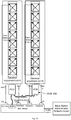
- a system of 2T4R base station and two facet dual-polarized electrical tilt antenna is shown in FIG. 3a .
- the specific connection is as follows: the dual-polarized antenna is composed of antenna oscillator group 201, phase shifter network 202 and electrical adjustment units 203 and 204. Electrical adjustment units 203 and 204 are set to connect the control portal of the external remote control unit (RCU) 206 through the electrical adjustment interface 205.
- the RCU has cascade function and can cascade aother RCU equipment by the cascade portal.
- the control side of RCU 206 is connected to the ASIG interface 207 of the base station by the signal cable.
- the radio frequency portals (CH1 / CH2 / CH3 / CH4) of the base station respectively connect to the antenna feeder portals (ANT1 / ANT2 / ANT3 / ANT4) of the polarized antenna through RF cable. It is defined here CH1, CH2, CH3 and CH4 respectively corresponding to the transceiver channel TX1 / RX1, receiving channel RX3, receiving channel RX4 and the transceiver channel TX2 / RX2 of the base station.
- the line order of the transmitting channel and the antenna portal requires ANT1 connecting to the CH1(TX1/ RX1), and ANT2 to CH4(TX2/ RX2).
- the base station network administration center connects to the base station, and configures the base station and the electrical tilt antennas.
- the steps of this exemplary embodiment are as follows: In step 1, base station works under downlink simulation load mode.
- step 2 Remotely configure the base station in downlink simulation load mode through base station network administration center, simulate user service to distribute the business data, to simulate the real scene of the base station measuring standing wave ratio or reverse power.
- step 2 configure electric down-tilt of the electrical tilt antennas to sample and calculate the standing wave ratio or reverse receiving power of the transmitting channel CH1 and CH4.
- base station network administration center sends the RCU 206 instructions through the base station ASIG interface 207 to configure electric down-tilt.
- the motor rotates to drive the electrical adjustment units 203, 204, and completes the operation on the phase shifter network 202.
- the phase of the antenna oscillator group 201 vibrates.
- the electric down-tilt of the antenna's vertical direction pattern changes. Every time electric down-tilt is adjusted by the electrical adjustment unit, the standing wave ratio (VSWR_TX1 / VSWR_TX2) or reverse received power (REV_TX1 / REV_TX2) of the transmitting channel CH1 and CH4 is sampled and counted. The down-tilt is stepped and traversed to certain degrees (taking 1 degree for example). The standing wave ratio or reverse receiving power corresponding to the transmitting channel CH1 and CH4 are obtained respectively. As shown in table 1.
- step 3 calculate the statistical characteristic parameters of the channel standing wave ratio or reverse receiving power of the transmitting channels as electric down-tilts changes,.
- the statistical characteristic parameters (such as variance) ⁇ TX1_A and ⁇ TX2_A of the standing wave ratio or reverse receiving power of the transmitting channels CH1 and CH4 can be obtained when the electrical adjustment unit A adjusts electric down-tilt.
- the statistical characteristic parameters of the standing wave ratio or reverse receiving power of the transmitting channel CH1 and CH4 are ⁇ TX1_B and ATX2_B.
- the above statistical characteristic parameters should be able to truly represent that it's caused only by the change of electric down-tilts.
- step 4 according to the antenna line order configuration requirements and the pre-determined threshold value, the four statistical characteristic parameters obtained in step 3 are determined, and the correctness of the antennas line order is given.
- a pre-determined threshold value X is set up according to the system. It is compared to the 4 variables obtained in step 3. The following results are obtained, as shown in table 2: Table 2 ⁇ TX1_A ⁇ X ⁇ TX1_B ⁇ X ⁇ TX2_A ⁇ X ⁇ TX2_B ⁇ X True False True False
- CH1 are connected to the antenna array that the RCU A located.
- CH4 are connected.to the antenna array that the RCU B located.
- the antenna configuration requires two transmitting channels must be on the same facet of the antenna. So the connection in Fig. 3B does not conform to the antenna configuration requirements of the 2T4R system. Thus, that the line order between the electrical tilt antennas and the base station is determined to be wrong.
- Table 8 Antenna Configuration Requirements of 4T4R CHI ⁇ -> RCUA CH2 ⁇ -> RCUA CH3 ⁇ -> RCUB CH4 ⁇ -> RCUB
- Table 9 ⁇ TX1_A ⁇ X ⁇ TX1_B ⁇ X ⁇ TX2_A ⁇ X ⁇ TX2_B ⁇ X ⁇ TX3 _A ⁇ X ⁇ TX3_B ⁇ X ⁇ TX4_A ⁇ X ⁇ TX4_B ⁇ X CH1 ⁇ -> RCU A False CH2 ⁇ -> RCU A False False CH3 ⁇ -> RCU B False CH4 ⁇ -> RCU B
- CH1 and CH2 are connected to antenna array that RCU A is located.
- CH3 and CH4 are connected to antenna array that RCU B is located.
- the connection in Fig. 4A conforms to the antenna configuration requirements of 4T4R system, so the connection line order between the electrical tilt antennas and the base station is determined to be correct.
- Table 11 ⁇ TX1_A ⁇ X ⁇ TX1_B ⁇ X ⁇ TX2_A ⁇ X ⁇ TX2_B ⁇ X ⁇ TX3_A ⁇ X ⁇ TX3_B ⁇ X ⁇ TX4_A ⁇ X ⁇ TX4_B ⁇ X CH1 ⁇ -> RCU A False CH2 ⁇ -> RCU B False CH3 ⁇ -> RCU A False False CH4 ⁇ -> RCU B
- CH1 and CH3 are connected to antenna array that RCU A is located.
- CH2 and CH4 are connected to antenna array that RCU B is located.
- the connection in Fig. 4B does not conform to the antenna configuration requirements of the 4T4R system, so the connection line order between the electrical tilt antennas and the base station is determined to be incorrect.
- the exemplary embodiments of the present disclosure provide a method and apparatus for automatically detecting connection line order of electrical tilt antennas. It makes use of the characteristics that the electrical adjustment of the electrical tilt antenna changes the antenna standing wave ratio or the reverse receiving power. It should be configured for an automatic identification and diagnosis on the cable connections line order between the multi-channel base stations and antenna systems. By configuring the electrical adjustment unit of each electrical tilt antenna in turn, the electric down-tilt changes.
- the base station samples the reverse receiving power or the standing wave ratio of every transmitting channel, and calculates the statistical characteristic parameters of reverse receiving power or standing wave ratio of every transmitting channel according to the pre-determined statistics algorithm. If the statistical characteristic parameter corresponding to every channel is greater than a pre-determined threshold value, then the channel and the antenna portals of the electrical adjustment unit are determined to be connected together. Ultimately, the connection line order between the multi-channel base stations and the antenna system is determined to be correct or not based on the system requirements of the antenna configuration.
- the technical solution provided by the exemplary embodiments of this invention can effectively reduce the manual cost of network engineering deployment, network optimization and network layout. It can also increase the network delivery speed, and improve network quality and consumer satisfaction.
- each module may or may not be physically separate, may or may not be a physical unit. It is possible to choose some or all of the modules to realize the purpose of the exemplary embodiments.
- each function module of the exemplary embodiments of this invention can be integrated in one processing module, or each module can be physically separated. It can also be two or more than two modules integrated in one module.
- the integrated modules can be implemented in hardware or in the form of hardware combined with software modules.
- the integrated module implemented as a software functional unit can be stored in a computer readable storage medium.
- the software function modules are stored in a storage medium including several instructions to make a computer equipment (personal computer, server, or network device, etc.) perform part of the processes of the method in the exemplary embodiments of this invention.
- the storage medium includes: USB flash disk, mobile hard disk, read-only Memory (ROM), Random Access Memory (RAM), disk or CD and other medium which can store the program code.
Landscapes
- Engineering & Computer Science (AREA)
- Computer Networks & Wireless Communication (AREA)
- Signal Processing (AREA)
- Mobile Radio Communication Systems (AREA)
Claims (3)
- Verfahren zur automatischen Erkennung der Anschlussleitungsreihenfolge zwischen den Zuführanschlüssen einer doppelt polarisierten Antenne mit mehreren Facetten mit elektrischer Kippung und den RF-Anschlüssen einer Multikanalbasisstation, dadurch gekennzeichnet, dass es die folgenden Schritte umfasst:Einstellen (101), durch eine elektrische Einstellungseinheit, von n elektrischen Abwärtskippungen der doppelt polarisierten Antenne mit mehreren Facetten, und Sammeln, durch die Antennenzuführanschlüsse, die in der elektrischen Einstellungseinheit platziert sind, von Stehwellenverhältniswerten der Signale, die für jede elektrische Abwärtskippung der übertragenden Kanäle der Basisstation reflektiert werden, wobei n eine ganze Zahl größer 2 ist; undBerechnen (102) der Varianz der gesammelten Stehwellenverhältniswerte entsprechend den n elektrischen Abwärtskippungen gemäß einem Varianzalgorithmus, wobei, wenn der Wert der Varianz größer als ein zuvor festgelegter Schwellenwert ist, bestimmt wird (103), dass die Anschlussleitungsreihenfolge zwischen der doppelt polarisierten Antenne mit mehreren Facetten und der Basisstation korrekt ist, wobei die Anschlussleitungsreihenfolge die Anschlussbeziehung zwischen den RF-Anschlüssen der Multikanalbasisstation und den Zuführanschlüssen der doppelt polarisierten Antenne mit mehreren Facetten ist.
- Vorrichtung zur automatischen Erkennung der Anschlussleitungsreihenfolge zwischen den Zuführanschlüssen einer doppelt polarisierten Antenne mit mehreren Facetten mit elektrischer Kippung und den RF-Anschlüssen einer Multikanalbasisstation, dadurch gekennzeichnet, dass sie Folgendes umfasst:Erwerbseinheit (11), die konfiguriert ist, um n elektrische Abwärtskippungen der doppelt polarisierten Antenne mit mehreren Facetten durch eine elektrische Einstellungseinheit einzustellen, und Sammeln von Stehwellenverhältniswerten der Signale, die für jede elektrische Abwärtskippung der übertragenden Kanäle der Basisstation reflektiert werden, durch die Antennenzuführanschlüsse, die in der elektrischen Einstellungseinheit platziert sind, wobei n eine ganze Zahl größer 2 ist;Berechnungseinheit (12), die konfiguriert ist, um die Varianz der gesammelten Stehwellenverhältniswerte entsprechend n elektrischen Abwärtskippungen gemäß einem Varianzalgorithmus zu berechnen; undBestimmungseinheit (13), die konfiguriert ist, um, wenn der Wert der Varianz größer als ein zuvor festgelegter Schwellenwert ist, zu bestimmen, dass die Anschlussleitungsreihenfolge zwischen der doppelt polarisierten Antenne mit mehreren Facetten und der Basisstation korrekt ist, undwobei die Anschlussleitungsreihenfolge die Anschlussbeziehung zwischen den RF-Anschlüssen der Multikanalbasisstation und den Zuführanschlüssen der doppelt polarisierten Antenne mit mehreren Facetten ist.
- Computerlesbares Speichermedium, auf dem Computerprogrammanweisungen gespeichert sind, die, wenn sie durch einen Prozessor ausgeführt werden, den Prozessor dazu veranlassen, ein Verfahren nach Anspruch 1 durchzuführen.
Applications Claiming Priority (2)
| Application Number | Priority Date | Filing Date | Title |
|---|---|---|---|
| CN201510369065.8A CN106330345B (zh) | 2015-06-29 | 2015-06-29 | 一种检测电调天线连接线序的方法和装置 |
| PCT/CN2016/072744 WO2017000552A1 (zh) | 2015-06-29 | 2016-01-29 | 一种检测电调天线连接线序的方法和装置 |
Publications (3)
| Publication Number | Publication Date |
|---|---|
| EP3316491A1 EP3316491A1 (de) | 2018-05-02 |
| EP3316491A4 EP3316491A4 (de) | 2018-06-27 |
| EP3316491B1 true EP3316491B1 (de) | 2020-08-12 |
Family
ID=57607636
Family Applications (1)
| Application Number | Title | Priority Date | Filing Date |
|---|---|---|---|
| EP16816917.5A Active EP3316491B1 (de) | 2015-06-29 | 2016-01-29 | Verfahren und vorrichtung zur erkennung der anschlussleitungsreihenfolge einer elektrischen kippantenne |
Country Status (5)
| Country | Link |
|---|---|
| US (1) | US10680328B2 (de) |
| EP (1) | EP3316491B1 (de) |
| JP (1) | JP6456523B2 (de) |
| CN (1) | CN106330345B (de) |
| WO (1) | WO2017000552A1 (de) |
Families Citing this family (8)
| Publication number | Priority date | Publication date | Assignee | Title |
|---|---|---|---|---|
| CN107959647B (zh) * | 2016-10-14 | 2022-02-25 | 中兴通讯股份有限公司 | 多载波系统的符号配置方法及装置、数据解调方法及装置 |
| BR112020012815A2 (pt) * | 2017-12-29 | 2020-11-24 | Huawei Technologies Co., Ltd. | método e aparelho de detecção de conexão de canal de radiofrequência |
| CN109890042B (zh) * | 2019-03-26 | 2022-04-22 | 中国联合网络通信集团有限公司 | 天馈接反的判断方法、装置、设备和可读存储介质 |
| WO2020246918A1 (en) * | 2019-06-03 | 2020-12-10 | Telefonaktiebolaget Lm Ericsson (Publ) | Neural network circuit remote electrical tilt antenna infrastructure management based on probability of actions |
| WO2021056268A1 (zh) | 2019-09-25 | 2021-04-01 | 华为技术有限公司 | 一种线序检测方法和检测系统 |
| CN113315590B (zh) * | 2020-02-26 | 2022-07-22 | 上海华为技术有限公司 | 一种线序检测方法以及多天线网络设备 |
| WO2024175203A1 (en) * | 2023-02-24 | 2024-08-29 | Telefonaktiebolaget Lm Ericsson (Publ) | Method for checking a cable mating of a multi-band antenna |
| CN118713772B (zh) * | 2023-03-27 | 2025-10-28 | 华为技术有限公司 | 线序确定方法及相关装置 |
Family Cites Families (19)
| Publication number | Priority date | Publication date | Assignee | Title |
|---|---|---|---|---|
| US6842431B2 (en) * | 1999-11-04 | 2005-01-11 | Lucent Technologies Inc. | Methods and apparatus for characterization, adjustment and optimization of wireless networks |
| CN101741418B (zh) * | 2008-11-04 | 2014-04-02 | 电信科学技术研究院 | 一种智能天线线序检测方法及装置 |
| CN101771197B (zh) | 2008-12-29 | 2013-11-06 | 中兴通讯股份有限公司 | 一种确定线缆顺序的方法及装置 |
| CN101989872B (zh) * | 2009-08-04 | 2013-07-24 | 鼎桥通信技术有限公司 | 一种天线跳线线序检测方法 |
| WO2011071425A1 (en) * | 2009-12-08 | 2011-06-16 | Telefonaktiebolaget L M Ericsson (Publ) | Method and arrangement for energy consumption balancing between base stations in a communication system |
| JP5411064B2 (ja) * | 2010-05-27 | 2014-02-12 | 京セラ株式会社 | 無線基地局、無線通信システム、及び制御方法 |
| JP5668754B2 (ja) * | 2010-05-31 | 2015-02-12 | 富士通株式会社 | 通信装置 |
| CN102136630B (zh) * | 2010-11-23 | 2015-06-03 | 华为技术有限公司 | 天线装置、天线系统和天线电调方法 |
| CN102014415B (zh) * | 2010-12-01 | 2014-07-02 | 中兴通讯股份有限公司 | 一种在线检测基站天馈系统的方法及基站系统及天线套件 |
| JP5696090B2 (ja) | 2012-04-18 | 2015-04-08 | 株式会社日立製作所 | アンテナ接続方向検出装置及びその方法 |
| CN105357755A (zh) | 2013-01-25 | 2016-02-24 | 华为技术有限公司 | 基站天馈口与天线端口连接关系的定位方法和装置 |
| US9854451B2 (en) * | 2013-09-24 | 2017-12-26 | Qatar University Qstp-B | Methods of optimizing tilt angle of an antenna |
| WO2015069159A1 (en) * | 2013-11-07 | 2015-05-14 | Telefonaktiebolaget L M Ericsson (Publ) | A network node and method for adjusting antenna parameters in a wireless communications system |
| US9491763B2 (en) * | 2013-11-07 | 2016-11-08 | Cellwize Wireless Technologies Ltd. | Methods and systems of adjusting antenna electrical tilt |
| CN106105291B (zh) * | 2014-01-24 | 2020-07-07 | 诺基亚通信公司 | 确定用于服务于无线电网络的垂直扇区化小区的天线的倾斜角的调整 |
| KR101635932B1 (ko) | 2014-04-22 | 2016-07-05 | 주식회사 케이엠더블유 | 이동통신 기지국 안테나 제어 장치 |
| US10382979B2 (en) * | 2014-12-09 | 2019-08-13 | Futurewei Technologies, Inc. | Self-learning, adaptive approach for intelligent analytics-assisted self-organizing-networks (SONs) |
| US9578530B2 (en) * | 2014-12-09 | 2017-02-21 | Futurewei Technologies, Inc. | Method and apparatus for determining cell states to adjust antenna configuration parameters |
| US10708788B2 (en) * | 2015-03-09 | 2020-07-07 | Telefonaktiebolaget Lm Erisson (Publ) | Controlling an antenna beam optimization algorithm |
-
2015
- 2015-06-29 CN CN201510369065.8A patent/CN106330345B/zh active Active
-
2016
- 2016-01-29 EP EP16816917.5A patent/EP3316491B1/de active Active
- 2016-01-29 JP JP2017559680A patent/JP6456523B2/ja active Active
- 2016-01-29 WO PCT/CN2016/072744 patent/WO2017000552A1/zh not_active Ceased
- 2016-01-29 US US15/738,737 patent/US10680328B2/en active Active
Non-Patent Citations (1)
| Title |
|---|
| None * |
Also Published As
| Publication number | Publication date |
|---|---|
| WO2017000552A1 (zh) | 2017-01-05 |
| CN106330345A (zh) | 2017-01-11 |
| JP6456523B2 (ja) | 2019-01-23 |
| JP2018523345A (ja) | 2018-08-16 |
| CN106330345B (zh) | 2020-03-06 |
| US10680328B2 (en) | 2020-06-09 |
| EP3316491A1 (de) | 2018-05-02 |
| US20180198205A1 (en) | 2018-07-12 |
| EP3316491A4 (de) | 2018-06-27 |
Similar Documents
| Publication | Publication Date | Title |
|---|---|---|
| US10680328B2 (en) | Method and apparatus for detecting connection line order of electrical tilting antenna | |
| KR101706882B1 (ko) | 무선 단말기의 성능을 테스팅하기 위한 방법 및 디바이스 | |
| EP3890199B1 (de) | Verfahren und system zur prüfung der drahtlosen leistung eines drahtlosen endgeräts | |
| EP2559168B1 (de) | Omnidirektionale erfassung von funkspektren | |
| US9116232B2 (en) | Methods and apparatus for testing satellite navigation system receiver performance | |
| US20160103199A1 (en) | System, method and computer-readable medium for estimating direction of arrival of a signal incident on at least one antenna array | |
| EP2230863A2 (de) | Verfahren zur Annäherung und Optimierung von Kapazitäts- und Abdeckungsverstärkung infolge der Verwendung von Multiantennen in zellularen Funknetzwerken | |
| CN106712864B (zh) | 一种智能天线性能测试及优化的方法及装置 | |
| EP3280070B1 (de) | Methode und vorrichtung zur erfassung und rückkopplung von kanalzustandsinformation | |
| CN109586813A (zh) | 用于执行测试测量的测量系统和方法 | |
| US20230344479A1 (en) | Wireless communication node adapted to radiate antenna beams of different types | |
| CN112425091B (zh) | 在无线通信系统中操作设备 | |
| EP2639970A1 (de) | Verfahren und Vorrichtung zur Steuerung einer drahtlosen Verbindung in einem MIMO-System unter Verwendung von direktionalen Multi-Sektor-Antennen | |
| CN110166143A (zh) | 一种基站性能的测试方法、设备及系统 | |
| EP1830485A1 (de) | Antenne für MIMO-Kommunikation | |
| EP3252964B1 (de) | Anpassung einer antennenkonfiguration einer endgerätevorrichtung in einem zellularen kommunikationssystem | |
| US20150156651A1 (en) | Detection of user terminal distribution in a wireless communication system | |
| EP2859723B1 (de) | Mimo-signalübertragungs- und -empfangsvorrichtung sowie system mit mindestens einer solchen vorrichtung | |
| EP3868042B1 (de) | Vorrichtung und verfahren zum empfangen und messen eines drahtlosen signals | |
| CN115550828A (zh) | 一种适用于tws蓝牙耳机适配测试系统的构建方法 | |
| US8405547B2 (en) | Self-provisioning antenna system and method | |
| CN120237444B (zh) | 一种mimo混合天线阵列及其设计与测量方法 | |
| Suharto et al. | Capacity Improvement Factor of HF Multi-Mode Skywave MIMO Channels | |
| US20250150146A1 (en) | Method and radio base station comprising antennas for providing coverage in a cell | |
| CN113747565B (zh) | 一种天线阵列实现无线终端定位系统 |
Legal Events
| Date | Code | Title | Description |
|---|---|---|---|
| STAA | Information on the status of an ep patent application or granted ep patent |
Free format text: STATUS: THE INTERNATIONAL PUBLICATION HAS BEEN MADE |
|
| PUAI | Public reference made under article 153(3) epc to a published international application that has entered the european phase |
Free format text: ORIGINAL CODE: 0009012 |
|
| STAA | Information on the status of an ep patent application or granted ep patent |
Free format text: STATUS: REQUEST FOR EXAMINATION WAS MADE |
|
| 17P | Request for examination filed |
Effective date: 20180104 |
|
| AK | Designated contracting states |
Kind code of ref document: A1 Designated state(s): AL AT BE BG CH CY CZ DE DK EE ES FI FR GB GR HR HU IE IS IT LI LT LU LV MC MK MT NL NO PL PT RO RS SE SI SK SM TR |
|
| AX | Request for extension of the european patent |
Extension state: BA ME |
|
| A4 | Supplementary search report drawn up and despatched |
Effective date: 20180525 |
|
| RIC1 | Information provided on ipc code assigned before grant |
Ipc: H01Q 3/34 20060101ALI20180518BHEP Ipc: H04B 1/707 20110101AFI20180518BHEP Ipc: H04W 64/00 20090101ALI20180518BHEP |
|
| DAV | Request for validation of the european patent (deleted) | ||
| DAX | Request for extension of the european patent (deleted) | ||
| RIC1 | Information provided on ipc code assigned before grant |
Ipc: H04W 64/00 20090101ALI20200214BHEP Ipc: H01Q 3/34 20060101ALI20200214BHEP Ipc: H04B 1/707 20110101AFI20200214BHEP |
|
| GRAP | Despatch of communication of intention to grant a patent |
Free format text: ORIGINAL CODE: EPIDOSNIGR1 |
|
| STAA | Information on the status of an ep patent application or granted ep patent |
Free format text: STATUS: GRANT OF PATENT IS INTENDED |
|
| INTG | Intention to grant announced |
Effective date: 20200421 |
|
| GRAS | Grant fee paid |
Free format text: ORIGINAL CODE: EPIDOSNIGR3 |
|
| GRAA | (expected) grant |
Free format text: ORIGINAL CODE: 0009210 |
|
| STAA | Information on the status of an ep patent application or granted ep patent |
Free format text: STATUS: THE PATENT HAS BEEN GRANTED |
|
| AK | Designated contracting states |
Kind code of ref document: B1 Designated state(s): AL AT BE BG CH CY CZ DE DK EE ES FI FR GB GR HR HU IE IS IT LI LT LU LV MC MK MT NL NO PL PT RO RS SE SI SK SM TR |
|
| REG | Reference to a national code |
Ref country code: CH Ref legal event code: EP |
|
| REG | Reference to a national code |
Ref country code: IE Ref legal event code: FG4D |
|
| REG | Reference to a national code |
Ref country code: DE Ref legal event code: R096 Ref document number: 602016041966 Country of ref document: DE |
|
| REG | Reference to a national code |
Ref country code: AT Ref legal event code: REF Ref document number: 1302571 Country of ref document: AT Kind code of ref document: T Effective date: 20200915 |
|
| REG | Reference to a national code |
Ref country code: LT Ref legal event code: MG4D |
|
| REG | Reference to a national code |
Ref country code: NL Ref legal event code: MP Effective date: 20200812 |
|
| PG25 | Lapsed in a contracting state [announced via postgrant information from national office to epo] |
Ref country code: SE Free format text: LAPSE BECAUSE OF FAILURE TO SUBMIT A TRANSLATION OF THE DESCRIPTION OR TO PAY THE FEE WITHIN THE PRESCRIBED TIME-LIMIT Effective date: 20200812 Ref country code: HR Free format text: LAPSE BECAUSE OF FAILURE TO SUBMIT A TRANSLATION OF THE DESCRIPTION OR TO PAY THE FEE WITHIN THE PRESCRIBED TIME-LIMIT Effective date: 20200812 Ref country code: NO Free format text: LAPSE BECAUSE OF FAILURE TO SUBMIT A TRANSLATION OF THE DESCRIPTION OR TO PAY THE FEE WITHIN THE PRESCRIBED TIME-LIMIT Effective date: 20201112 Ref country code: GR Free format text: LAPSE BECAUSE OF FAILURE TO SUBMIT A TRANSLATION OF THE DESCRIPTION OR TO PAY THE FEE WITHIN THE PRESCRIBED TIME-LIMIT Effective date: 20201113 Ref country code: BG Free format text: LAPSE BECAUSE OF FAILURE TO SUBMIT A TRANSLATION OF THE DESCRIPTION OR TO PAY THE FEE WITHIN THE PRESCRIBED TIME-LIMIT Effective date: 20201112 Ref country code: LT Free format text: LAPSE BECAUSE OF FAILURE TO SUBMIT A TRANSLATION OF THE DESCRIPTION OR TO PAY THE FEE WITHIN THE PRESCRIBED TIME-LIMIT Effective date: 20200812 Ref country code: FI Free format text: LAPSE BECAUSE OF FAILURE TO SUBMIT A TRANSLATION OF THE DESCRIPTION OR TO PAY THE FEE WITHIN THE PRESCRIBED TIME-LIMIT Effective date: 20200812 |
|
| REG | Reference to a national code |
Ref country code: AT Ref legal event code: MK05 Ref document number: 1302571 Country of ref document: AT Kind code of ref document: T Effective date: 20200812 |
|
| PG25 | Lapsed in a contracting state [announced via postgrant information from national office to epo] |
Ref country code: IS Free format text: LAPSE BECAUSE OF FAILURE TO SUBMIT A TRANSLATION OF THE DESCRIPTION OR TO PAY THE FEE WITHIN THE PRESCRIBED TIME-LIMIT Effective date: 20201212 Ref country code: PL Free format text: LAPSE BECAUSE OF FAILURE TO SUBMIT A TRANSLATION OF THE DESCRIPTION OR TO PAY THE FEE WITHIN THE PRESCRIBED TIME-LIMIT Effective date: 20200812 Ref country code: NL Free format text: LAPSE BECAUSE OF FAILURE TO SUBMIT A TRANSLATION OF THE DESCRIPTION OR TO PAY THE FEE WITHIN THE PRESCRIBED TIME-LIMIT Effective date: 20200812 Ref country code: LV Free format text: LAPSE BECAUSE OF FAILURE TO SUBMIT A TRANSLATION OF THE DESCRIPTION OR TO PAY THE FEE WITHIN THE PRESCRIBED TIME-LIMIT Effective date: 20200812 Ref country code: RS Free format text: LAPSE BECAUSE OF FAILURE TO SUBMIT A TRANSLATION OF THE DESCRIPTION OR TO PAY THE FEE WITHIN THE PRESCRIBED TIME-LIMIT Effective date: 20200812 |
|
| PG25 | Lapsed in a contracting state [announced via postgrant information from national office to epo] |
Ref country code: RO Free format text: LAPSE BECAUSE OF FAILURE TO SUBMIT A TRANSLATION OF THE DESCRIPTION OR TO PAY THE FEE WITHIN THE PRESCRIBED TIME-LIMIT Effective date: 20200812 Ref country code: DK Free format text: LAPSE BECAUSE OF FAILURE TO SUBMIT A TRANSLATION OF THE DESCRIPTION OR TO PAY THE FEE WITHIN THE PRESCRIBED TIME-LIMIT Effective date: 20200812 Ref country code: CZ Free format text: LAPSE BECAUSE OF FAILURE TO SUBMIT A TRANSLATION OF THE DESCRIPTION OR TO PAY THE FEE WITHIN THE PRESCRIBED TIME-LIMIT Effective date: 20200812 Ref country code: EE Free format text: LAPSE BECAUSE OF FAILURE TO SUBMIT A TRANSLATION OF THE DESCRIPTION OR TO PAY THE FEE WITHIN THE PRESCRIBED TIME-LIMIT Effective date: 20200812 Ref country code: SM Free format text: LAPSE BECAUSE OF FAILURE TO SUBMIT A TRANSLATION OF THE DESCRIPTION OR TO PAY THE FEE WITHIN THE PRESCRIBED TIME-LIMIT Effective date: 20200812 |
|
| REG | Reference to a national code |
Ref country code: DE Ref legal event code: R097 Ref document number: 602016041966 Country of ref document: DE |
|
| PG25 | Lapsed in a contracting state [announced via postgrant information from national office to epo] |
Ref country code: ES Free format text: LAPSE BECAUSE OF FAILURE TO SUBMIT A TRANSLATION OF THE DESCRIPTION OR TO PAY THE FEE WITHIN THE PRESCRIBED TIME-LIMIT Effective date: 20200812 Ref country code: AL Free format text: LAPSE BECAUSE OF FAILURE TO SUBMIT A TRANSLATION OF THE DESCRIPTION OR TO PAY THE FEE WITHIN THE PRESCRIBED TIME-LIMIT Effective date: 20200812 Ref country code: AT Free format text: LAPSE BECAUSE OF FAILURE TO SUBMIT A TRANSLATION OF THE DESCRIPTION OR TO PAY THE FEE WITHIN THE PRESCRIBED TIME-LIMIT Effective date: 20200812 |
|
| PLBE | No opposition filed within time limit |
Free format text: ORIGINAL CODE: 0009261 |
|
| STAA | Information on the status of an ep patent application or granted ep patent |
Free format text: STATUS: NO OPPOSITION FILED WITHIN TIME LIMIT |
|
| PG25 | Lapsed in a contracting state [announced via postgrant information from national office to epo] |
Ref country code: SK Free format text: LAPSE BECAUSE OF FAILURE TO SUBMIT A TRANSLATION OF THE DESCRIPTION OR TO PAY THE FEE WITHIN THE PRESCRIBED TIME-LIMIT Effective date: 20200812 |
|
| 26N | No opposition filed |
Effective date: 20210514 |
|
| PG25 | Lapsed in a contracting state [announced via postgrant information from national office to epo] |
Ref country code: MC Free format text: LAPSE BECAUSE OF FAILURE TO SUBMIT A TRANSLATION OF THE DESCRIPTION OR TO PAY THE FEE WITHIN THE PRESCRIBED TIME-LIMIT Effective date: 20200812 Ref country code: SI Free format text: LAPSE BECAUSE OF FAILURE TO SUBMIT A TRANSLATION OF THE DESCRIPTION OR TO PAY THE FEE WITHIN THE PRESCRIBED TIME-LIMIT Effective date: 20200812 |
|
| REG | Reference to a national code |
Ref country code: CH Ref legal event code: PL |
|
| GBPC | Gb: european patent ceased through non-payment of renewal fee |
Effective date: 20210129 |
|
| PG25 | Lapsed in a contracting state [announced via postgrant information from national office to epo] |
Ref country code: LU Free format text: LAPSE BECAUSE OF NON-PAYMENT OF DUE FEES Effective date: 20210129 |
|
| REG | Reference to a national code |
Ref country code: BE Ref legal event code: MM Effective date: 20210131 |
|
| PG25 | Lapsed in a contracting state [announced via postgrant information from national office to epo] |
Ref country code: LI Free format text: LAPSE BECAUSE OF NON-PAYMENT OF DUE FEES Effective date: 20210131 Ref country code: GB Free format text: LAPSE BECAUSE OF NON-PAYMENT OF DUE FEES Effective date: 20210129 Ref country code: CH Free format text: LAPSE BECAUSE OF NON-PAYMENT OF DUE FEES Effective date: 20210131 |
|
| PG25 | Lapsed in a contracting state [announced via postgrant information from national office to epo] |
Ref country code: IE Free format text: LAPSE BECAUSE OF NON-PAYMENT OF DUE FEES Effective date: 20210129 |
|
| PG25 | Lapsed in a contracting state [announced via postgrant information from national office to epo] |
Ref country code: IS Free format text: LAPSE BECAUSE OF FAILURE TO SUBMIT A TRANSLATION OF THE DESCRIPTION OR TO PAY THE FEE WITHIN THE PRESCRIBED TIME-LIMIT Effective date: 20201212 |
|
| PG25 | Lapsed in a contracting state [announced via postgrant information from national office to epo] |
Ref country code: BE Free format text: LAPSE BECAUSE OF NON-PAYMENT OF DUE FEES Effective date: 20210131 |
|
| PG25 | Lapsed in a contracting state [announced via postgrant information from national office to epo] |
Ref country code: PT Free format text: LAPSE BECAUSE OF FAILURE TO SUBMIT A TRANSLATION OF THE DESCRIPTION OR TO PAY THE FEE WITHIN THE PRESCRIBED TIME-LIMIT Effective date: 20201214 |
|
| PG25 | Lapsed in a contracting state [announced via postgrant information from national office to epo] |
Ref country code: CY Free format text: LAPSE BECAUSE OF FAILURE TO SUBMIT A TRANSLATION OF THE DESCRIPTION OR TO PAY THE FEE WITHIN THE PRESCRIBED TIME-LIMIT Effective date: 20200812 |
|
| PG25 | Lapsed in a contracting state [announced via postgrant information from national office to epo] |
Ref country code: HU Free format text: LAPSE BECAUSE OF FAILURE TO SUBMIT A TRANSLATION OF THE DESCRIPTION OR TO PAY THE FEE WITHIN THE PRESCRIBED TIME-LIMIT; INVALID AB INITIO Effective date: 20160129 |
|
| PG25 | Lapsed in a contracting state [announced via postgrant information from national office to epo] |
Ref country code: MK Free format text: LAPSE BECAUSE OF FAILURE TO SUBMIT A TRANSLATION OF THE DESCRIPTION OR TO PAY THE FEE WITHIN THE PRESCRIBED TIME-LIMIT Effective date: 20200812 |
|
| PG25 | Lapsed in a contracting state [announced via postgrant information from national office to epo] |
Ref country code: MT Free format text: LAPSE BECAUSE OF FAILURE TO SUBMIT A TRANSLATION OF THE DESCRIPTION OR TO PAY THE FEE WITHIN THE PRESCRIBED TIME-LIMIT Effective date: 20200812 |
|
| PG25 | Lapsed in a contracting state [announced via postgrant information from national office to epo] |
Ref country code: TR Free format text: LAPSE BECAUSE OF FAILURE TO SUBMIT A TRANSLATION OF THE DESCRIPTION OR TO PAY THE FEE WITHIN THE PRESCRIBED TIME-LIMIT Effective date: 20200812 |
|
| PGFP | Annual fee paid to national office [announced via postgrant information from national office to epo] |
Ref country code: FR Payment date: 20251208 Year of fee payment: 11 |
|
| PGFP | Annual fee paid to national office [announced via postgrant information from national office to epo] |
Ref country code: DE Payment date: 20251203 Year of fee payment: 11 |
|
| PGFP | Annual fee paid to national office [announced via postgrant information from national office to epo] |
Ref country code: IT Payment date: 20251219 Year of fee payment: 11 |