EP3868042B1 - Vorrichtung und verfahren zum empfangen und messen eines drahtlosen signals - Google Patents
Vorrichtung und verfahren zum empfangen und messen eines drahtlosen signals Download PDFInfo
- Publication number
- EP3868042B1 EP3868042B1 EP19874264.5A EP19874264A EP3868042B1 EP 3868042 B1 EP3868042 B1 EP 3868042B1 EP 19874264 A EP19874264 A EP 19874264A EP 3868042 B1 EP3868042 B1 EP 3868042B1
- Authority
- EP
- European Patent Office
- Prior art keywords
- antennas
- antenna
- antenna set
- signal
- oriented
- Prior art date
- Legal status (The legal status is an assumption and is not a legal conclusion. Google has not performed a legal analysis and makes no representation as to the accuracy of the status listed.)
- Active
Links
Images




Classifications
-
- H—ELECTRICITY
- H04—ELECTRIC COMMUNICATION TECHNIQUE
- H04B—TRANSMISSION
- H04B17/00—Monitoring; Testing
- H04B17/10—Monitoring; Testing of transmitters
- H04B17/11—Monitoring; Testing of transmitters for calibration
- H04B17/12—Monitoring; Testing of transmitters for calibration of transmit antennas, e.g. of the amplitude or phase
-
- H—ELECTRICITY
- H04—ELECTRIC COMMUNICATION TECHNIQUE
- H04B—TRANSMISSION
- H04B7/00—Radio transmission systems, i.e. using radiation field
- H04B7/02—Diversity systems; Multi-antenna system, i.e. transmission or reception using multiple antennas
- H04B7/10—Polarisation diversity; Directional diversity
-
- H—ELECTRICITY
- H01—ELECTRIC ELEMENTS
- H01Q—ANTENNAS, i.e. RADIO AERIALS
- H01Q3/00—Arrangements for changing or varying the orientation or the shape of the directional pattern of the waves radiated from an antenna or antenna system
- H01Q3/02—Arrangements for changing or varying the orientation or the shape of the directional pattern of the waves radiated from an antenna or antenna system using mechanical movement of antenna or antenna system as a whole
-
- H—ELECTRICITY
- H04—ELECTRIC COMMUNICATION TECHNIQUE
- H04B—TRANSMISSION
- H04B17/00—Monitoring; Testing
- H04B17/20—Monitoring; Testing of receivers
- H04B17/25—Monitoring; Testing of receivers taking multiple measurements
- H04B17/252—Monitoring; Testing of receivers taking multiple measurements measuring signals from different transmission points or directions of arrival, e.g. in multi RAT or dual connectivity
-
- H—ELECTRICITY
- H04—ELECTRIC COMMUNICATION TECHNIQUE
- H04B—TRANSMISSION
- H04B7/00—Radio transmission systems, i.e. using radiation field
- H04B7/02—Diversity systems; Multi-antenna system, i.e. transmission or reception using multiple antennas
- H04B7/04—Diversity systems; Multi-antenna system, i.e. transmission or reception using multiple antennas using two or more spaced independent antennas
- H04B7/08—Diversity systems; Multi-antenna system, i.e. transmission or reception using multiple antennas using two or more spaced independent antennas at the receiving station
- H04B7/0802—Diversity systems; Multi-antenna system, i.e. transmission or reception using multiple antennas using two or more spaced independent antennas at the receiving station using antenna selection
Definitions
- the disclosure relates to a wireless signal. More particularly, the disclosure relates to a device and method for receiving and measuring a wireless signal.
- the 5G or pre-5G communication system is also called a ⁇ Beyond 4G Network' or a 'Post Long Term Evolution (LTE) System.
- the 5G communication system is considered to be implemented in higher frequency (mmWave) bands, e.g., 60GHz bands, so as to accomplish higher data rates.
- mmWave e.g., 60GHz bands
- MIMO massive multiple-input multiple-output
- FD-MIMO Full Dimensional MIMO
- array antenna an analog beam forming, large scale antenna techniques are discussed in 5G communication systems.
- RANs Cloud Radio Access Networks
- D2D device-to-device
- wireless backhaul moving network
- cooperative communication Coordinated Multi-Points (CoMP), reception-end interference cancellation and the like.
- CoMP Coordinated Multi-Points
- FSK Hybrid frequency shift keying
- FQAM quadrature amplitude modulation
- SWSC sliding window superposition coding
- ACM advanced coding modulation
- FBMC filter bank multi carrier
- NOMA non-orthogonal multiple access
- SCMA sparse code multiple access
- EP 2 405 534 A1 discloses an electronic device having wireless communications circuitry including an adjustable antenna system coupled to a radio-frequency transceiver, wherein the adjustable antenna system includes one or more adjustable electrical components that are controlled by storage and processing circuitry in the electronic device, wherein the adjustable electrical components include switches and components that can be adjusted between numerous different states.
- EP 0 897 230 A2 discloses a wireless local area network system comprising: a wireless local area network master station for supporting communication between satellite stations belonging to the master station; and one or more wireless local area network satellite stations.
- the satellite station in the relevant local area network comprises: an antenna for dynamically changing a directivity characteristic when receiving electric waves from the master station; control frame transmitting means for transmitting control frames prior to the commencement of communication; and antenna directivity characteristic controlling means for determining such a directivity characteristic that the receiving electric field intensity of a carrier wave transmitted from the master station when receiving the relevant control frame may become a maximum by changing the directivity characteristic of said antenna, and the master station in the relevant local area network system comprises carrier wave transmitting means for starting to transmit carrier waves when receiving said control frame.
- an aspect of the disclosure is to provide a device and method for effectively receiving and measuring a wireless signal.
- Another aspect of the disclosure is to provide a device and method for receiving and measuring a wireless signal by using a directional antenna.
- a device for measuring a wireless signal is provided as defined in the appended claims.
- a method for measuring a wireless signal is provided as defined in the appended claims.
- a device and method according to various embodiments of the disclosure can effectively analyze a high-frequency wireless signal by adjusting oriented directions of directional antennas and receiving and measuring the signal.
- the disclosure relates to a device and method for receiving and measuring a wireless signal.
- the disclosure describes a technique for receiving and measuring a wireless signal by using a directional antenna.
- a device equipment for receiving and measuring a wireless signal
- a wireless measurement device equipment for receiving and measuring a wireless signal
- an “analysis device” equipment for analyzing a wireless signal
- wireless signal analysis device equipment for analyzing a wireless signal
- measurement equipment equipment for receiving and measuring a wireless signal
- the disclosure proposes various embodiments for securing a signal reception range equal to that of an omnidirectional antenna by using directional antennas.
- FIG. 1A illustrates a configuration of a measurement device according to an embodiment of the disclosure.
- the measurement device includes a signal analyzer 110 and a receiver 120.
- the signal analyzer 110 analyzes wireless signals received through the receiver 120.
- the signal analyzer 110 may analyze various factors related to the signals (for example, antenna gain, system gain, cable loss, signal strength, etc.).
- An analysis result obtained by the signal analyzer 110 may be generated for each antenna, and analysis data for each antenna may include characteristic values on a time axis.
- the signal analyzer 110 may include representative values (for example, average, movement average, etc.) for all the antennas or a subset of the antennas.
- the signal analyzer 110 may include a controller 112 and a storage unit 114.
- the controller 112 may be implemented as at least one processor, perform an analysis operation, and control an operation of another element (for example, the receiver 120).
- the storage unit 114 may store a program, an instruction, and configuration data, which may be required for an operation of the measurement device, and store an analysis result.
- the controller 112 may control the measurement device to perform operations according to various embodiments described below.
- the receiver 120 receives a wireless signal.
- the receiver 120 may include at least one antenna and a reception circuit (for example, an amplifier and a signal path).
- at least one antenna included in the receiver 120 may be a directional antenna.
- the receiver 120 may be configured as shown in FIG. 1B .
- the measurement device may further include a display unit and an input unit.
- the display unit may display an analysis result of a signal and an interface for controlling the measurement device according to the control of the controller 112.
- the input unit may detect a user's input and provide the detected input to the controller 112.
- the input unit may include a keyboard, a button, and the like.
- FIG. 1B illustrates a configuration of a receiver included in a measurement device according to an embodiment of the disclosure.
- FIG. 1B may be understood as a configuration of the receiver 120.
- the receiver 120 includes an antenna unit 122, a switching unit 124, and an amplifier 126.
- the antenna unit 122 includes a plurality of antennas, and the plurality of antennas are classified into a plurality of antenna sets.
- the plurality of antenna sets include a first antenna set 122a and a second antenna set 122b.
- the plurality of antennas included in the antenna unit 122 may be directional antennas, and the directional antennas may be arranged toward directions different from each other.
- the directional antennas may be implemented as a horn antenna.
- Directional antennas included in at least one set (for example, the first antenna set 122a) among the plurality of antenna sets may be designed to adjust an oriented angle.
- a driving means for adjusting oriented angles of the directional antennas may be further included.
- Each of the oriented angles of the directional antennas may be adjusted independently.
- Directional antennas included in at least one set (for example, the second antenna set 122b) among the plurality of antenna sets may be designed to have a fixed oriented angle.
- the switching unit 124 is connected to the plurality of antennas included in the antenna unit 122 and connects at least one of the plurality of antennas to the amplifier 126.
- the switching unit 124 may provide signals received through the plurality of antennas to the amplifier 126 by sequentially establishing paths with the plurality of antennas according to the control of the controller 112.
- the switching unit 124 may include at least one switching board or switch board.
- the switching unit 124 may include one switch.
- the switching unit 124 may connect one antenna to the amplifier 126 at a specific time. When all the plurality of antennas are connected, losses corresponding to the number of connected antennas may occur. In order to prevent such a loss, only one switch is used. By using only one switch, only one antenna is connected to a reception path at a time, the reception path is cycled, and thus data can be collected while a loss is minimized.
- the switching unit 124 may include as many switches as the number of antenna sets.
- the amplifier 126 amplifies a signal received through the antenna unit 122.
- the amplifier 126 may be implemented as a low noise amplifier (LNA).
- the receiver 120 may include the amplifier 126 to address a problem in that a radio wave arrival distance of a high frequency is shortened.
- the amplifier 126 may include one LNA.
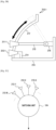
- FIG. 2A illustrates an implementation example of a receiver according to an embodiment of the disclosure.
- FIG. 2B illustrates an implementation example of a receiver according to an embodiment of the disclosure.
- FIG. 2C illustrates an implementation example of a receiver according to an embodiment of the disclosure.
- two antenna sets in the antenna unit 122 have a dual structure along a vertical axis.
- the antenna unit 122 may include a housing and various support members for fixing antennas.
- Antennas 211-1, 211-2, 211-3, ... 211-N included in the first antenna set 122a disposed in an upper end portion 210a of a semi-circular sphere have a structure capable of adjusting an oriented angle
- antennas 212-1, 212-2, 212-3, ... 212-N included in the second antenna set 122b disposed in a lower end portion 210b of the semi-circular sphere have fixed oriented angles.
- each antenna set may include 16 antennas having a beam width of 25 degrees, and the antennas may be configured to cover a 360-degree direction.
- the antenna unit 122 includes N antenna pairs 210-1, 210-2, 210-3, ... 210-N.
- One antenna pair may cover the same horizontal angle
- the antenna 211-1 disposed in the upper end portion 210a may cover a vertical angle in a predetermined range by adjusting an oriented angle in a vertical direction.
- the controller 112 may generate a control signal for vertical movement of the antenna 211-1.
- various embodiments of the disclosure may provide an effect, such as using an omnidirectional antenna, by arranging directional antennas in a hemispherical shape.
- the directional antennas may be configured to cover a 360-degree direction in a horizontal direction and may be arranged in a plurality of rows in a vertical direction. Further, at least one upper end row of the antennas may be configured to be movable by an angular degree.
- the antenna pair 210-1 may be configured as shown in FIG. 2B .
- the antenna 212-1 is fixed to a base member 213 through a first fixing member 214.
- the antenna 211-1 is connected to a driving unit 216 through a second fixing member 215, and the driving unit 216 is fixed to the base member 213.
- the antenna 211-1 moves along a guide member 217, and a vertical oriented angle is changed according to the movement.
- the antennas 212-1 to 212-N included in the second antenna set 122b may be arranged in a circular shape and may be connected to the switching unit 124.
- the antennas 211-1 to 211-N included in the first antenna set 122a may also be arranged in a circular shape and may be connected to the switching unit 124.
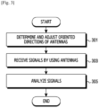
- FIG. 3 illustrates a flowchart for receiving and measuring a wireless signal by a measurement device according to an embodiment of the disclosure.
- the measurement device determines oriented directions of antennas and controls the antennas according to the determined oriented directions in operation 301.
- the oriented directions of the antennas may be determined according to measurement scheduling.
- the oriented directions of the antennas may be determined according to a measurement algorithm or may be determined according to a user's command. A user can monitor a received signal and, if necessary, can determine an appropriate arrival angle of the signal by moving the antennas in the upper end portion.
- the measurement device may adjust vertical angles of antennas included in at least one antenna set to arrange the antennas. Otherwise, the measurement device may adjust so as to allow a designated antenna to be oriented to a specific horizontal angle by rotating the antenna unit.
- the measurement device receives signals by using the antennas.
- the measurement device may control a switch so as to receive and collect signals by sequentially using the plurality of antennas.
- the measurement device may collect signals received by the plurality of antennas through one reception path.
- the reception path may include an LNA. That is, the measurement device may amplify the signals received through the antennas.
- the measurement device analyzes the signals. That is, the measurement device may analyze the signals received through the plurality of antennas. Since information on an antenna which receives the signals is provided, an angle of arrival (AOA) of the signals may be obtained from an oriented direction of the antenna.
- AOA angle of arrival
- the plurality of antennas are adjusted to have different oriented directions. Accordingly, an arrival angle of a received signal may be easily identified from an oriented direction of an antenna.
- the measurement device may estimate and correct the oriented angle of the antenna. For example, the estimation and correction of the oriented angle of the antenna may be performed using a global positioning system (GPS) signal.
- GPS global positioning system
- the measurement device may estimate and correct a reception direction angle of each antenna by applying a differential GPS (DGPS). For example, the measurement device may estimate an oriented direction of a specific antenna by a signal of the DGPS by linking directions of antenna #1 and the DGPS.
- DGPS differential GPS
- the measurement device may estimate an oriented direction of a specific antenna by a signal of the DGPS by linking directions of antenna #1 and the DGPS.
- a movement direction of the measurement device is identified using a GPS or DGPS, it may be determined that an oriented direction of an antenna facing the movement direction corresponds to the movement direction. That is, since the movement direction measured by using the GPS or DGPS includes longitude and latitude coordinates, the measurement device may calculate an azimuth angle from the coordinate values, and may determine the calculated azimuth angle as an oriented direction of a corresponding antenna, that is, an arrival angle.
- the measurement device may link corrected direction information to the remaining antennas, based on beam widths and the number of the remaining antennas.
- the measurement device may estimate arrival angles for the remaining antennas. For example, if 16 antennas having a beam width of 22.5 degrees are arranged, when antenna #1 is aligned to 0 degrees, the arrival angles of the remaining antennas may be corrected by adding or subtracting a multiple of 22.5 to an arrival angle of antenna #1. For example, an arrival angle of antenna #2 adjacent to antenna #1 may be replaced with a value obtained by correcting the arrival angle of antenna #1 by 22.5 degrees.
- a signal reaching each antenna is linked to the DGPS, and all the signals may be stored and recorded together with an arrival angle and the amount (e.g., signal strength) of a received signal.
- information on the signals may be stored after interval averaging.
- a wireless signal may be distorted while passing through a channel. For example, when a transmitter terminal or a receiver terminal moves, a difference between a frequency of a signal at the time of transmission and a frequency of a signal at the time of reception may occur due to the Doppler effect.
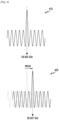
- FIG. 4 illustrates an influence of the Doppler effect on a wireless signal according to an embodiment of the disclosure.
- a frequency of a peak component of a signal 410 may be 28.005 GHz at the time of transmission.
- a frequency of a peak component of a signal 420 may be 28.007 GHz at the time of reception. That is, a phenomenon in which the peak component moves on a frequency axis may occur.
- the measurement device since a frequency of a signal transmitted for measurement may not be constant, the measurement device receives a signal within a predetermined bandwidth by using short divided bands, and selectively processes an interval in which a peak signal is received within a spectrum of the same reception time zone, so as to measure only a signal to be actually measured. Example operations for measurement will be described hereinafter with reference to FIG. 5 .
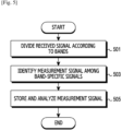
- FIG. 5 illustrates a flowchart for extracting a measurement signal by a measurement device according to an embodiment of the disclosure.
- the measurement device divides a received signal according to bands in operation 501.
- Each band has a smaller width than the total bandwidth for signal reception. Accordingly, one received signal is divided into a plurality of band-specific partial signals.
- the partial signals may be referred to as narrowband signals.
- FIG. 6 illustrates examples of an extraction result of a measurement signal according to an embodiment of the disclosure.
- the whole band may be divided into 11 bands, and each of a signal 610 and a signal 620 may be divided into 11 partial signals.
- the measurement device identifies a measurement signal among the band-specific signals in operation 503. That is, the measurement device identifies a partial signal including a signal transmitted for measurement, among the plurality of partial signals.
- the measurement signal may be identified according to a predefined criterion.
- the predefined criterion may be defined based on at least one of a value, a pattern, or a magnitude of a signal.
- the partial signal including the measurement signal may be a partial signal including a peak component.
- a partial signal 612 among the partial signals of the signal 610 and a partial signal 622 among the partial signals of the signal 620 may be selected as a signal including the measurement signal.
- the measurement device stores and analyzes the measurement signal.
- the measurement device may store partial signals which are identified to include the measurement signal and discard the remaining partial signals. Thereafter, the measurement device may analyze the stored partial signals.
- the partial signal including the measurement signal may be the partial signal including the peak component.
- the measurement device may first perform an operation of determining whether another interference signal is detected in a corresponding band. If no other interference signal is detected, it is possible to assume that the peak component is the measurement signal during the measurement.
- FIG. 7 illustrates an implementation example of a measurement device according to an embodiment of the disclosure.
- the measurement device may be installed in a vehicle 710.
- the signal analyzer 110 of the measurement device may be installed in the vehicle 710 and the receiver 120 may be installed on the vehicle 710.
- the receiver 120 may switch a plurality of directional antennas and receive signals like an omnidirectional antenna, and the signal analyzer 110 may extract and analyze only a required signal among the received signals.
- a GPS receiver 720 may be further installed on the vehicle 710, and the measurement device may estimate and correct angles of antennas by using a GPS signal received through the GPS receiver 720.
- the measurement device installed in the vehicle 710 may be used for signal reception and measurement.
- a signal may be transmitted from a terminal or a base station of a target system.
- the signal may be transmitted by a device designed for measurement, for example, a signal generator 730 and a transmitter 740.
- signal collection may be configured with reference to the maximum signal after a bandwidth (BW) is configured at the time of signal reception.
- BW bandwidth
- absolute angle allocation is configured for each antenna in cooperation with a DGPS in order to identify an arrival angle of a signal.
- measurements at various arrival angles of a signal may be performed due to the use of multiple antennas and antenna position change.
- beamforming and multiple input multiple output (MIMO) channel analysis data may be secured through reception of a plurality of signals for each antenna.
- data acquisition may be performed several hundred times per second by using a switch, and signal strength and information on an arrival angle may be generated together for each received signal, and thus are easy to be utilized.
- Massive data including information on an arrival angle is utilized, so that regional channel estimation may be facilitated in a mmWave, and regional channel estimation information may be used to improve the accuracy of system design.
- the collected data may be used to extract individual antenna characteristics and the best signal for each interval, and an extracted signal may contribute to the improvement of the propagation model accuracy.
- a computer-readable storage medium for storing one or more programs (software modules) may be provided.
- the one or more programs stored in the computer-readable storage medium may be configured for execution by one or more processors within an electronic device.
- the at least one program may include instructions that cause the electronic device to perform the methods according to various embodiments of the disclosure as defined by the appended claims and/or disclosed herein.
- the programs may be stored in non-volatile memories including a random access memory and a flash memory, a read only memory (ROM), an electrically erasable programmable read only memory (EEPROM), a magnetic disc storage device, a compact disc-ROM (CD-ROM), digital versatile discs (DVDs), or other types of optical storage devices, or a magnetic cassette.
- ROM read only memory
- EEPROM electrically erasable programmable read only memory
- CD-ROM compact disc-ROM
- DVDs digital versatile discs
- any combination of some or all of the above may form a memory in which the program is stored.
- a plurality of such memories may be included in the electronic device.
- the programs may be stored in an attachable storage device which is accessible through communication networks such as the Internet, Intranet, local area network (LAN), wide area network (WAN), and storage area network (SAN), or a combination thereof.
- a storage device may access a device for performing an embodiment of the disclosure via an external port.
- a separate storage device on the communication network may access the device for performing an embodiment of the disclosure.
- an element included in the disclosure is expressed in the singular or the plural according to a presented embodiment.
- the singular form or plural form is selected for convenience of description suitable for the presented situation, and various embodiments of the disclosure are not limited to a single element or multiple elements thereof.
- either multiple elements expressed in the description may be configured as a single element or a single element in the description may be configured as multiple elements.
Landscapes
- Engineering & Computer Science (AREA)
- Computer Networks & Wireless Communication (AREA)
- Signal Processing (AREA)
- Physics & Mathematics (AREA)
- Electromagnetism (AREA)
- Variable-Direction Aerials And Aerial Arrays (AREA)
- Quality & Reliability (AREA)
- Mobile Radio Communication Systems (AREA)
Claims (15)
- Vorrichtung zum Messen eines drahtlosen Signals, wobei die Vorrichtung umfasst:einen ersten Antennensatz (122a), der eine Vielzahl von Antennen (211-1 bis 211-N) mit einstellbar ausgerichteten Richtungen umfasst;einen zweiten Antennensatz (122b), der eine Vielzahl von Antennen (212-1 bis 212-N) mit fest ausgerichteten Richtungen umfasst; undmindestens einen Prozessor (112), der konfiguriert ist zum:Bestimmen einer ausgerichteten Richtung von mindestens einer der Vielzahl von Antennen (211-1 bis 211-N; 212-1 bis 212-N),Einstellen (301) eines vertikalen Winkels von mindestens einer der Vielzahl von Antennen (211-1 bis 211-N), die im ersten Antennensatz (122a) enthalten sind, basierend auf dem Bestimmen,Drehen (301) des ersten Antennensatzes (122a) und des zweiten Antennensatzes (122b) in einen bestimmten horizontalen Winkel basierend auf dem Bestimmen,Bestimmen einer bestimmten Antenne, die eine ausgerichtete Richtung aufweist, die einer Bewegungsrichtung der Vorrichtung entspricht, undEmpfangen (303) und Analysieren (305) von drahtlosen Signalen unter Verwendung des ersten Antennensatzes (122a) und des zweiten Antennensatzes (122b),wobei die Vielzahl von Antennen (211-1 bis 211-N; 212-1 bis 212-N), die in dem ersten Antennensatz (122a) und dem zweiten Antennensatz (122b) enthalten sind, in einer Halbkugelform angeordnet sind, der erste Antennensatz (122a) an einem oberen Ende (210a) der Halbkugelform angeordnet ist und der zweite Antennensatz (122b) an einem unteren Ende (210b) der Halbkugelform angeordnet ist,wobei eine der Vielzahl von Antennen (211-1 bis 211-N), die in dem ersten Antennensatz (122a) enthalten sind, und eine der Vielzahl von Antennen (212-1 bis 212-N), die in dem zweiten Antennensatz (122b) enthalten sind, in einem gleichen horizontalen Winkel angeordnet sind, um ein Antennenpaar (210-1 bis 210-N) zu bilden,wobei jede in dem Antennenpaar (210-1 bis 210-N) enthaltene Antenne einen anderen vertikalen Winkel aufweist.
- Vorrichtung nach Anspruch 1, wobei der mindestens eine Prozessor (112) ferner konfiguriert ist zum:Bestimmen und Einstellen eines horizontalen Winkels der bestimmten Antenne basierend auf Global Positioning System-, GPS,-Signalen, undErfassen der Bewegungsrichtung basierend auf Positionsinformationen von einem GPS.
- Vorrichtung nach Anspruch 1, wobei die Vielzahl von Antennen (211-1 bis 211-N), die in dem ersten Antennensatz (122a) enthalten sind, konfiguriert sind, um in einer vertikalen Richtung beweglich zu sein, um eine ausgerichtete Richtung einer vertikalen Achse einzustellen.
- Vorrichtung nach Anspruch 1, ferner umfassend eine Schalteinheit (124), die konfiguriert ist, um mindestens eine der Vielzahl von Antennen mit einem Empfangsweg zu verbinden.
- Vorrichtung nach Anspruch 4, wobei der mindestens eine Prozessor (112) ferner konfiguriert ist, um die Vielzahl von Antennen zu steuern, die unter Verwendung der Schalteinheit (124) sequentiell mit dem Empfangsweg zu verbinden sind.
- Vorrichtung nach Anspruch 1, ferner umfassend einen Verstärker (126), der so konfiguriert ist, dass er ein über mindestens eine der Vielzahl von Antennen empfangenes Signal verstärkt.
- Vorrichtung nach Anspruch 1, wobei der mindestens eine Prozessor (112) ferner konfiguriert ist zum:Teilen (501) eines Empfangssignals in bandspezifische Teilsignale, undAuswählen (503) mindestens eines ein Messsignal enthaltenden Teilsignals aus den Teilsignalen.
- Vorrichtung nach Anspruch 7, wobei das mindestens eine Teilsignal, das das Messsignal enthält, ein Teilsignal umfasst, das eine Spitzenkomponente des empfangenen Signals enthält.
- Vorrichtung nach Anspruch 1, wobei der mindestens eine Prozessor (112) ferner konfiguriert ist, um Winkelinformationen in Bezug auf die ausgerichtete Richtung der mindestens einen der Vielzahl von Antennen als Informationen über einen Ankunftswinkel eines über die Antenne empfangenen Signals zu speichern.
- Verfahren zum Messen eines drahtlosen Signals, wobei das Verfahren umfasst:Bestimmen einer ausgerichteten Richtung von mindestens einer aus einer Vielzahl von Antennen (211-1 bis 211-N; 212-1 bis 212-N), wobei die mindestens eine aus der Vielzahl von Antennen (211-1 bis 211-N; 212-1 bis 212-N) umfasst:eine Vielzahl von Antennen (211-1 bis 211-N), die in einem ersten Antennensatz (122a) mit einstellbar ausgerichtete Richtungen enthalten sind, undeine Vielzahl von Antennen (212-1 bis 212-N), die in einem zweiten Antennensatz (122b) mit fest ausgerichtete Richtungen enthalten sind,Einstellen (301) eines vertikalen Winkels von mindestens einer der Vielzahl von Antennen (211-1 bis 211-N), die in dem ersten Antennensatz (122a) enthalten sind, basierend auf dem Bestimmen,Drehen (301) des ersten Antennensatzes (122a) und des zweiten Antennensatzes (122b) auf einen bestimmten horizontalen Winkel basierend auf dem Bestimmen,Bestimmen einer bestimmten Antenne, die eine ausgerichtete Richtung aufweist, die einer Bewegungsrichtung der Vorrichtung entspricht, undEmpfangen (303) und Analysieren (305) von drahtlosen Signalen unter Verwendung des ersten Antennensatzes (122a) und des zweiten Antennensatzes (122b),wobei die Vielzahl von Antennen (211-1 bis 211-N; 212-1 bis 212-N), die in dem ersten Antennensatz (122a) und dem zweiten Antennensatz (122b) enthalten sind, in einer Halbkugelform angeordnet sind, der erste Antennensatz (122a) an einem oberen Ende (210a) der Halbkugelform angeordnet ist und der zweite Antennensatz (122b) an einem unteren Ende (210b) der Halbkugelform angeordnet ist,wobei eine der Vielzahl von Antennen (211-1 bis 211-N), die in dem ersten Antennensatz (122a) enthalten sind, und eine der Vielzahl von Antennen (212-1 bis 212-N), die in dem zweiten Antennensatz (122b) enthalten sind, in einem gleichen horizontalen Winkel angeordnet sind, um ein Antennenpaar (210-1 bis 210-N) zu bilden,wobei jede in dem Antennenpaar (210-1 bis 210-N) enthaltene Antenne einen anderen vertikalen Winkel aufweist.
- Verfahren nach Anspruch 10, ferner umfassend:Bestimmen und Einstellen eines horizontalen Winkels der bestimmten Antenne basierend auf Global Positioning System-, GPS,-Signalen,Erfassen der Bewegungsrichtung basierend auf Positionsinformationen des GPS.
- Verfahren nach Anspruch 10, wobei das Einstellen der einstellbar ausgerichteten Richtungen der Vielzahl von Antennen (211-1 bis 211-N) das Bewegen der Vielzahl von Antennen, die in dem ersten Antennensatz (122a) enthalten sind, in einer vertikalen Richtung umfasst, um eine ausgerichtete Richtung einer vertikalen Achse einzustellen.
- Verfahren nach Anspruch 10, wobei das Empfangen der drahtlosen Signale Steuern der Vielzahl von Antennen umfasst, die sequentiell mit einem Empfangspfad zu verbinden sind.
- Verfahren nach Anspruch 10, ferner umfassend Verstärken eines über mindestens eine der Vielzahl von Antennen empfangenen Signals.
- Verfahren nach Anspruch 10, wobei das Analysieren der drahtlosen Signale umfasst:Teilen eines Empfangssignals in bandspezifische Teilsignale; undAuswählen mindestens eines Teilsignals, das ein Messsignal enthält, unter den Teilsignalen.
Applications Claiming Priority (2)
| Application Number | Priority Date | Filing Date | Title |
|---|---|---|---|
| KR1020180125493A KR102562821B1 (ko) | 2018-10-19 | 2018-10-19 | 무선 신호를 수신 및 측정하기 위한 장치 및 방법 |
| PCT/KR2019/013684 WO2020080860A1 (en) | 2018-10-19 | 2019-10-17 | Device and method for receiving and measuring wireless signal |
Publications (3)
| Publication Number | Publication Date |
|---|---|
| EP3868042A1 EP3868042A1 (de) | 2021-08-25 |
| EP3868042A4 EP3868042A4 (de) | 2021-12-08 |
| EP3868042B1 true EP3868042B1 (de) | 2025-06-11 |
Family
ID=70281310
Family Applications (1)
| Application Number | Title | Priority Date | Filing Date |
|---|---|---|---|
| EP19874264.5A Active EP3868042B1 (de) | 2018-10-19 | 2019-10-17 | Vorrichtung und verfahren zum empfangen und messen eines drahtlosen signals |
Country Status (4)
| Country | Link |
|---|---|
| US (1) | US10972198B2 (de) |
| EP (1) | EP3868042B1 (de) |
| KR (1) | KR102562821B1 (de) |
| WO (1) | WO2020080860A1 (de) |
Families Citing this family (2)
| Publication number | Priority date | Publication date | Assignee | Title |
|---|---|---|---|---|
| KR102562821B1 (ko) * | 2018-10-19 | 2023-08-02 | 삼성전자주식회사 | 무선 신호를 수신 및 측정하기 위한 장치 및 방법 |
| EP4145726B1 (de) | 2021-09-03 | 2024-03-06 | Rohde & Schwarz GmbH & Co. KG | Funkfrequenzabtastsystem und verfahren zur prüfung von mobilen netzwerken |
Family Cites Families (23)
| Publication number | Priority date | Publication date | Assignee | Title |
|---|---|---|---|---|
| BE755884A (fr) * | 1969-09-08 | 1971-02-15 | Huels Chemische Werke Ag | Polyalkenameres et procede pour les preparer |
| JPH0669714A (ja) | 1992-08-21 | 1994-03-11 | Nec Corp | 移動体衛星通信用アンテナ装置 |
| JP3792013B2 (ja) * | 1997-08-12 | 2006-06-28 | 富士通株式会社 | ワイヤレスlanおよびシステム内送受信装置 |
| KR100585714B1 (ko) | 2003-05-26 | 2006-06-07 | 엘지전자 주식회사 | 기지국 원형배열안테나의 신호원 서칭장치 및 방법 |
| JP4943280B2 (ja) * | 2007-09-20 | 2012-05-30 | Dxアンテナ株式会社 | マルチビームアンテナ |
| US8462066B2 (en) * | 2009-03-20 | 2013-06-11 | Rammohan Malasani | Long-distance wireless-LAN directional antenna alignment |
| US9070969B2 (en) * | 2010-07-06 | 2015-06-30 | Apple Inc. | Tunable antenna systems |
| US9024823B2 (en) * | 2011-05-27 | 2015-05-05 | Apple Inc. | Dynamically adjustable antenna supporting multiple antenna modes |
| US9608331B1 (en) * | 2011-09-08 | 2017-03-28 | Ethertronics, Inc. | SAR reduction architecture and technique for wireless devices |
| US9331397B2 (en) * | 2013-03-18 | 2016-05-03 | Apple Inc. | Tunable antenna with slot-based parasitic element |
| US9337537B2 (en) * | 2013-05-08 | 2016-05-10 | Apple Inc. | Antenna with tunable high band parasitic element |
| KR20150059104A (ko) | 2013-11-21 | 2015-05-29 | 한국전자통신연구원 | 해상 광대역 무선통신 시스템에서의 지향성 안테나 트래킹 장치 및 그 방법 |
| US9531061B2 (en) * | 2014-09-03 | 2016-12-27 | Apple Inc. | Electronic device antenna with reduced lossy mode |
| DE102016000694B4 (de) * | 2016-01-22 | 2018-06-07 | Lennart Jürges | Mobile Ladestation sowie System zur Ortung eines Ballspielgerätes |
| US10153554B2 (en) * | 2016-08-31 | 2018-12-11 | Apple Inc. | Electronic device antennas with harmonic resonances |
| CN109964369A (zh) * | 2016-11-18 | 2019-07-02 | 华为技术有限公司 | 一种天线系统、一种虚拟天线端口的映射方法及装置 |
| EP3352295A1 (de) | 2017-01-18 | 2018-07-25 | BAE SYSTEMS plc | Antennenanordnung |
| KR102649097B1 (ko) | 2017-01-13 | 2024-03-20 | 삼성전자 주식회사 | 이동 통신 시스템에서 드라이브 테스트를 수행하는 방법 및 장치 |
| KR20180099130A (ko) | 2017-02-28 | 2018-09-05 | 삼성전자주식회사 | 무선 통신 시스템에서 네트워크 환경 관리 방법 및 장치 |
| KR101845716B1 (ko) * | 2017-07-20 | 2018-04-06 | 주식회사 티에이엔지니어링 | 고주파용 트래킹 안테나 |
| US10756414B2 (en) * | 2017-11-02 | 2020-08-25 | Dell Products, Lp | System and method for operating a living antenna aperture mechanism |
| US11050496B2 (en) * | 2018-05-21 | 2021-06-29 | National Instruments Corporation | Over-the-air testing of millimeter wave integrated circuits with integrated antennas |
| KR102562821B1 (ko) * | 2018-10-19 | 2023-08-02 | 삼성전자주식회사 | 무선 신호를 수신 및 측정하기 위한 장치 및 방법 |
-
2018
- 2018-10-19 KR KR1020180125493A patent/KR102562821B1/ko active Active
-
2019
- 2019-10-17 EP EP19874264.5A patent/EP3868042B1/de active Active
- 2019-10-17 WO PCT/KR2019/013684 patent/WO2020080860A1/en not_active Ceased
- 2019-10-17 US US16/655,800 patent/US10972198B2/en active Active
Also Published As
| Publication number | Publication date |
|---|---|
| KR20200044559A (ko) | 2020-04-29 |
| KR102562821B1 (ko) | 2023-08-02 |
| WO2020080860A1 (en) | 2020-04-23 |
| US20200127744A1 (en) | 2020-04-23 |
| EP3868042A1 (de) | 2021-08-25 |
| EP3868042A4 (de) | 2021-12-08 |
| US10972198B2 (en) | 2021-04-06 |
Similar Documents
| Publication | Publication Date | Title |
|---|---|---|
| US10794984B2 (en) | System, method and computer-readable medium for estimating direction of arrival of a signal incident on at least one antenna array | |
| EP2356847B1 (de) | Bestimmung der konfiguration einer basisstation eines mobiltelefonienetzes | |
| KR102207844B1 (ko) | 적어도 하나의 안테나 배열에 입사하는 신호의 도착 방향을 추정하는 시스템, 방법, 그리고 컴퓨터 판독가능 매체 | |
| US20210328343A1 (en) | In-field millimeter-wave phased array radiation pattern estimation and validation | |
| US10405360B2 (en) | Method and equipment for establishing millimetre connection | |
| US20220159480A1 (en) | Beamforming method and apparatus, radio access network device, and readable storage medium | |
| KR102067156B1 (ko) | 안테나 모드 스티어링 회로와 장치 및 방법 | |
| US20110250921A1 (en) | Omni-Directional Sensing of Radio Spectra | |
| JP2010533391A (ja) | アンテナパターンを調整することにより移動体無線通信システムのパフォーマンスを改善するための方法と装置 | |
| EP3316491B1 (de) | Verfahren und vorrichtung zur erkennung der anschlussleitungsreihenfolge einer elektrischen kippantenne | |
| CN111316571B (zh) | 高效波束搜索 | |
| US10972198B2 (en) | Device and method for receiving and measuring wireless signal | |
| EP3252964B1 (de) | Anpassung einer antennenkonfiguration einer endgerätevorrichtung in einem zellularen kommunikationssystem | |
| Fan et al. | 6g radio channel sounding: Challenges and potential solutions | |
| KR100979608B1 (ko) | 두개의 안테나들 또는 이의 균등물을 사용하여 네비게이션비컨 신호를 검출하는 방법 | |
| Fan et al. | Recent advances on OTA testing for 5G antenna systems in multi-probe anechoic chamber setups | |
| KR20150095008A (ko) | 스펙트럼 센싱 방법 및 그 장치 | |
| EP2517376B1 (de) | Verfahren zur unterdrückung von interferenzen aus der entgegengesetzten richtung | |
| Singh et al. | Implementation of an adaptive beam forming antenna for radio technology | |
| Maddio et al. | Fast and Precise Direction of Arrival Estimation Based on Space and Frequency Division Multiple Access | |
| Alejos et al. | Hierarchical beamforming strategies for source detection with linear arrays at 26 GHz | |
| Naik et al. | Simulation of direction of arrival and beamforming algorithms used in smart antenna system for software-defined radio | |
| Wang | Analysis of CW MIMO Channel Measurements in Urban Cellular Scenarios | |
| Dailleux et al. | Millimeter wave spatial multiplexing: Feasibility and performance of a short range 2× 2 link |
Legal Events
| Date | Code | Title | Description |
|---|---|---|---|
| STAA | Information on the status of an ep patent application or granted ep patent |
Free format text: STATUS: THE INTERNATIONAL PUBLICATION HAS BEEN MADE |
|
| PUAI | Public reference made under article 153(3) epc to a published international application that has entered the european phase |
Free format text: ORIGINAL CODE: 0009012 |
|
| STAA | Information on the status of an ep patent application or granted ep patent |
Free format text: STATUS: REQUEST FOR EXAMINATION WAS MADE |
|
| 17P | Request for examination filed |
Effective date: 20210518 |
|
| AK | Designated contracting states |
Kind code of ref document: A1 Designated state(s): AL AT BE BG CH CY CZ DE DK EE ES FI FR GB GR HR HU IE IS IT LI LT LU LV MC MK MT NL NO PL PT RO RS SE SI SK SM TR |
|
| A4 | Supplementary search report drawn up and despatched |
Effective date: 20211109 |
|
| RIC1 | Information provided on ipc code assigned before grant |
Ipc: H04B 7/08 20060101ALI20211103BHEP Ipc: H04B 7/10 20170101ALI20211103BHEP Ipc: H04B 17/20 20150101ALI20211103BHEP Ipc: H04B 17/30 20150101AFI20211103BHEP |
|
| DAV | Request for validation of the european patent (deleted) | ||
| DAX | Request for extension of the european patent (deleted) | ||
| STAA | Information on the status of an ep patent application or granted ep patent |
Free format text: STATUS: EXAMINATION IS IN PROGRESS |
|
| 17Q | First examination report despatched |
Effective date: 20230315 |
|
| REG | Reference to a national code |
Ref country code: DE Ref legal event code: R079 Free format text: PREVIOUS MAIN CLASS: H04B0017300000 Ipc: H04B0017120000 Ref country code: DE Ref legal event code: R079 Ref document number: 602019071121 Country of ref document: DE Free format text: PREVIOUS MAIN CLASS: H04B0017300000 Ipc: H04B0017120000 |
|
| GRAP | Despatch of communication of intention to grant a patent |
Free format text: ORIGINAL CODE: EPIDOSNIGR1 |
|
| STAA | Information on the status of an ep patent application or granted ep patent |
Free format text: STATUS: GRANT OF PATENT IS INTENDED |
|
| RIC1 | Information provided on ipc code assigned before grant |
Ipc: H04B 17/12 20150101AFI20250113BHEP |
|
| INTG | Intention to grant announced |
Effective date: 20250128 |
|
| GRAS | Grant fee paid |
Free format text: ORIGINAL CODE: EPIDOSNIGR3 |
|
| GRAA | (expected) grant |
Free format text: ORIGINAL CODE: 0009210 |
|
| STAA | Information on the status of an ep patent application or granted ep patent |
Free format text: STATUS: THE PATENT HAS BEEN GRANTED |
|
| AK | Designated contracting states |
Kind code of ref document: B1 Designated state(s): AL AT BE BG CH CY CZ DE DK EE ES FI FR GB GR HR HU IE IS IT LI LT LU LV MC MK MT NL NO PL PT RO RS SE SI SK SM TR |
|
| REG | Reference to a national code |
Ref country code: GB Ref legal event code: FG4D |
|
| REG | Reference to a national code |
Ref country code: CH Ref legal event code: EP |
|
| REG | Reference to a national code |
Ref country code: IE Ref legal event code: FG4D |
|
| REG | Reference to a national code |
Ref country code: DE Ref legal event code: R096 Ref document number: 602019071121 Country of ref document: DE |
|
| REG | Reference to a national code |
Ref country code: NL Ref legal event code: FP |
|
| PG25 | Lapsed in a contracting state [announced via postgrant information from national office to epo] |
Ref country code: FI Free format text: LAPSE BECAUSE OF FAILURE TO SUBMIT A TRANSLATION OF THE DESCRIPTION OR TO PAY THE FEE WITHIN THE PRESCRIBED TIME-LIMIT Effective date: 20250611 Ref country code: ES Free format text: LAPSE BECAUSE OF FAILURE TO SUBMIT A TRANSLATION OF THE DESCRIPTION OR TO PAY THE FEE WITHIN THE PRESCRIBED TIME-LIMIT Effective date: 20250611 |
|
| REG | Reference to a national code |
Ref country code: LT Ref legal event code: MG9D |
|
| PG25 | Lapsed in a contracting state [announced via postgrant information from national office to epo] |
Ref country code: GR Free format text: LAPSE BECAUSE OF FAILURE TO SUBMIT A TRANSLATION OF THE DESCRIPTION OR TO PAY THE FEE WITHIN THE PRESCRIBED TIME-LIMIT Effective date: 20250912 Ref country code: NO Free format text: LAPSE BECAUSE OF FAILURE TO SUBMIT A TRANSLATION OF THE DESCRIPTION OR TO PAY THE FEE WITHIN THE PRESCRIBED TIME-LIMIT Effective date: 20250911 |
|
| PGFP | Annual fee paid to national office [announced via postgrant information from national office to epo] |
Ref country code: NL Payment date: 20250922 Year of fee payment: 7 |
|
| PG25 | Lapsed in a contracting state [announced via postgrant information from national office to epo] |
Ref country code: BG Free format text: LAPSE BECAUSE OF FAILURE TO SUBMIT A TRANSLATION OF THE DESCRIPTION OR TO PAY THE FEE WITHIN THE PRESCRIBED TIME-LIMIT Effective date: 20250611 |
|
| PGFP | Annual fee paid to national office [announced via postgrant information from national office to epo] |
Ref country code: GB Payment date: 20250922 Year of fee payment: 7 |
|
| PG25 | Lapsed in a contracting state [announced via postgrant information from national office to epo] |
Ref country code: HR Free format text: LAPSE BECAUSE OF FAILURE TO SUBMIT A TRANSLATION OF THE DESCRIPTION OR TO PAY THE FEE WITHIN THE PRESCRIBED TIME-LIMIT Effective date: 20250611 |
|
| PG25 | Lapsed in a contracting state [announced via postgrant information from national office to epo] |
Ref country code: RS Free format text: LAPSE BECAUSE OF FAILURE TO SUBMIT A TRANSLATION OF THE DESCRIPTION OR TO PAY THE FEE WITHIN THE PRESCRIBED TIME-LIMIT Effective date: 20250911 |
|
| PG25 | Lapsed in a contracting state [announced via postgrant information from national office to epo] |
Ref country code: LV Free format text: LAPSE BECAUSE OF FAILURE TO SUBMIT A TRANSLATION OF THE DESCRIPTION OR TO PAY THE FEE WITHIN THE PRESCRIBED TIME-LIMIT Effective date: 20250611 |
|
| PG25 | Lapsed in a contracting state [announced via postgrant information from national office to epo] |
Ref country code: PT Free format text: LAPSE BECAUSE OF FAILURE TO SUBMIT A TRANSLATION OF THE DESCRIPTION OR TO PAY THE FEE WITHIN THE PRESCRIBED TIME-LIMIT Effective date: 20251013 |
|
| REG | Reference to a national code |
Ref country code: AT Ref legal event code: MK05 Ref document number: 1803089 Country of ref document: AT Kind code of ref document: T Effective date: 20250611 |
|
| PG25 | Lapsed in a contracting state [announced via postgrant information from national office to epo] |
Ref country code: IS Free format text: LAPSE BECAUSE OF FAILURE TO SUBMIT A TRANSLATION OF THE DESCRIPTION OR TO PAY THE FEE WITHIN THE PRESCRIBED TIME-LIMIT Effective date: 20251011 |
|
| PGFP | Annual fee paid to national office [announced via postgrant information from national office to epo] |
Ref country code: DE Payment date: 20250922 Year of fee payment: 7 |
|
| PG25 | Lapsed in a contracting state [announced via postgrant information from national office to epo] |
Ref country code: AT Free format text: LAPSE BECAUSE OF FAILURE TO SUBMIT A TRANSLATION OF THE DESCRIPTION OR TO PAY THE FEE WITHIN THE PRESCRIBED TIME-LIMIT Effective date: 20250611 Ref country code: SM Free format text: LAPSE BECAUSE OF FAILURE TO SUBMIT A TRANSLATION OF THE DESCRIPTION OR TO PAY THE FEE WITHIN THE PRESCRIBED TIME-LIMIT Effective date: 20250611 |
|
| PG25 | Lapsed in a contracting state [announced via postgrant information from national office to epo] |
Ref country code: CZ Free format text: LAPSE BECAUSE OF FAILURE TO SUBMIT A TRANSLATION OF THE DESCRIPTION OR TO PAY THE FEE WITHIN THE PRESCRIBED TIME-LIMIT Effective date: 20250611 |
|
| PG25 | Lapsed in a contracting state [announced via postgrant information from national office to epo] |
Ref country code: PL Free format text: LAPSE BECAUSE OF FAILURE TO SUBMIT A TRANSLATION OF THE DESCRIPTION OR TO PAY THE FEE WITHIN THE PRESCRIBED TIME-LIMIT Effective date: 20250611 |
|
| PG25 | Lapsed in a contracting state [announced via postgrant information from national office to epo] |
Ref country code: EE Free format text: LAPSE BECAUSE OF FAILURE TO SUBMIT A TRANSLATION OF THE DESCRIPTION OR TO PAY THE FEE WITHIN THE PRESCRIBED TIME-LIMIT Effective date: 20250611 |
|
| PG25 | Lapsed in a contracting state [announced via postgrant information from national office to epo] |
Ref country code: RO Free format text: LAPSE BECAUSE OF FAILURE TO SUBMIT A TRANSLATION OF THE DESCRIPTION OR TO PAY THE FEE WITHIN THE PRESCRIBED TIME-LIMIT Effective date: 20250611 Ref country code: SK Free format text: LAPSE BECAUSE OF FAILURE TO SUBMIT A TRANSLATION OF THE DESCRIPTION OR TO PAY THE FEE WITHIN THE PRESCRIBED TIME-LIMIT Effective date: 20250611 |
|
| REG | Reference to a national code |
Ref country code: DE Ref legal event code: R097 Ref document number: 602019071121 Country of ref document: DE |
|
| PG25 | Lapsed in a contracting state [announced via postgrant information from national office to epo] |
Ref country code: DK Free format text: LAPSE BECAUSE OF FAILURE TO SUBMIT A TRANSLATION OF THE DESCRIPTION OR TO PAY THE FEE WITHIN THE PRESCRIBED TIME-LIMIT Effective date: 20250611 |
|
| PG25 | Lapsed in a contracting state [announced via postgrant information from national office to epo] |
Ref country code: IT Free format text: LAPSE BECAUSE OF FAILURE TO SUBMIT A TRANSLATION OF THE DESCRIPTION OR TO PAY THE FEE WITHIN THE PRESCRIBED TIME-LIMIT Effective date: 20250611 |
|
| PLBE | No opposition filed within time limit |
Free format text: ORIGINAL CODE: 0009261 |
|
| STAA | Information on the status of an ep patent application or granted ep patent |
Free format text: STATUS: NO OPPOSITION FILED WITHIN TIME LIMIT |
|
| REG | Reference to a national code |
Ref country code: CH Ref legal event code: L10 Free format text: ST27 STATUS EVENT CODE: U-0-0-L10-L00 (AS PROVIDED BY THE NATIONAL OFFICE) Effective date: 20260423 |