EP3890199B1 - Verfahren und system zur prüfung der drahtlosen leistung eines drahtlosen endgeräts - Google Patents
Verfahren und system zur prüfung der drahtlosen leistung eines drahtlosen endgeräts Download PDFInfo
- Publication number
- EP3890199B1 EP3890199B1 EP19891243.8A EP19891243A EP3890199B1 EP 3890199 B1 EP3890199 B1 EP 3890199B1 EP 19891243 A EP19891243 A EP 19891243A EP 3890199 B1 EP3890199 B1 EP 3890199B1
- Authority
- EP
- European Patent Office
- Prior art keywords
- testing
- antenna
- dut
- transmitting
- antennas
- Prior art date
- Legal status (The legal status is an assumption and is not a legal conclusion. Google has not performed a legal analysis and makes no representation as to the accuracy of the status listed.)
- Active
Links
Images




Classifications
-
- H—ELECTRICITY
- H04—ELECTRIC COMMUNICATION TECHNIQUE
- H04B—TRANSMISSION
- H04B17/00—Monitoring; Testing
- H04B17/10—Monitoring; Testing of transmitters
- H04B17/15—Performance testing
-
- G—PHYSICS
- G01—MEASURING; TESTING
- G01R—MEASURING ELECTRIC VARIABLES; MEASURING MAGNETIC VARIABLES
- G01R29/00—Arrangements for measuring or indicating electric quantities not covered by groups G01R19/00 - G01R27/00
- G01R29/08—Measuring electromagnetic field characteristics
- G01R29/10—Radiation diagrams of antennas
- G01R29/105—Radiation diagrams of antennas using anechoic chambers; Chambers or open field sites used therefor
-
- H—ELECTRICITY
- H04—ELECTRIC COMMUNICATION TECHNIQUE
- H04B—TRANSMISSION
- H04B17/00—Monitoring; Testing
- H04B17/0082—Monitoring; Testing using service channels; using auxiliary channels
- H04B17/0087—Monitoring; Testing using service channels; using auxiliary channels using auxiliary channels or channel simulators
-
- H—ELECTRICITY
- H04—ELECTRIC COMMUNICATION TECHNIQUE
- H04B—TRANSMISSION
- H04B17/00—Monitoring; Testing
- H04B17/10—Monitoring; Testing of transmitters
- H04B17/15—Performance testing
- H04B17/16—Test equipment located at the transmitter
-
- H—ELECTRICITY
- H04—ELECTRIC COMMUNICATION TECHNIQUE
- H04B—TRANSMISSION
- H04B17/00—Monitoring; Testing
- H04B17/20—Monitoring; Testing of receivers
- H04B17/29—Performance testing
- H04B17/294—Performance testing with test equipment located at the receiver
-
- H—ELECTRICITY
- H04—ELECTRIC COMMUNICATION TECHNIQUE
- H04B—TRANSMISSION
- H04B17/00—Monitoring; Testing
- H04B17/30—Monitoring; Testing of propagation channels
- H04B17/391—Modelling the propagation channel
- H04B17/3912—Simulation models, e.g. distribution of spectral power density or received signal strength indicator [RSSI] for a given geographic region
-
- H—ELECTRICITY
- H04—ELECTRIC COMMUNICATION TECHNIQUE
- H04B—TRANSMISSION
- H04B7/00—Radio transmission systems, i.e. using radiation field
- H04B7/02—Diversity systems; Multi-antenna system, i.e. transmission or reception using multiple antennas
- H04B7/04—Diversity systems; Multi-antenna system, i.e. transmission or reception using multiple antennas using two or more spaced independent antennas
- H04B7/0413—MIMO systems
Definitions
- the present disclosure relates to a field of wireless communication technology, and more particularly, to a method and a system for testing wireless performance of a MIMO wireless terminal.
- MIMO Multiple Input Multiple Output
- 4G fourth generation
- 5G fifth generation
- the wireless performance of the MIMO terminal depends on several factors, such as sensitivity of the receiver of the terminal, noise, transmitter power, antenna correlation, matching degree between the antenna, receiver and transmitter, baseband processing, and wireless propagation environment.
- An Over the Air (OTA) test solution for the MIMO terminal provides a method and a test system for evaluating and testing the wireless performance of the MIMO terminal in a controlled environment.
- the OTA test of the MIMO terminal is not only the basis for mobile operators to check the performance of mobile terminals and to issue terminal network access licenses, but also the technical means of terminal manufacturers in the process of research and development and quality control.
- OTA testing is also currently recognized as a test method that can evaluate the true wireless performance of MIMO wireless terminals by the 3rd Generation Partnership Project (3GPP) and the China Communications Standards Association (CCSA).
- 3GPP 3rd Generation Partnership Project
- CCSA China Communications Standards Association
- 3GPP provides two standard OTA test solutions, i.e., Multiple Probe Anechoic Chamber (MPAC) method and Radiated Two Stage (RTS) method.
- MPAC Multiple Probe Anechoic Chamber
- RTS Radiated Two Stage
- the most critical index for evaluating the performance of downlink MIMO is the throughput rate.
- MIMO uses diversity technology to increase the communication rate.
- the electromagnetic wave space propagation environment that is, the channel model
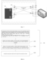
- Fig. 1 illustrates a multipath environment in which a wireless MIMO terminal is located, which includes a direct path from the base station to the terminal, a transmission path of each building, and the Doppler effect.
- the MIMO OTA test needs to simulate a specified channel model, and then the throughput rate is tested under the model.
- the MPAC method adopts a plurality of antennas (such as 16 antennas) around a DUT (device under test) together with a channel emulator to simulate the MIMO channel, which is an intuitive method.
- the first step of the RTS method is acquiring a receiving antenna pattern of the DUT.
- the second step is generating a throughput rate test signal based on the acquired receiving antenna pattern in combination with the channel model, and then the throughput test signal is fed to a corresponding receiver by radiation to perform a throughput test.
- the RTS method uses simple and efficient hardware, with small system errors and high system stability, as illustrated in Fig. 3 . Due to its advantages in various aspects, RTS has gradually become the most mainstream MIMO test method.
- Wireless terminal testing is not only concerned with reception performance, but also transmission performance.
- downlink MIMO testing is standardized and industrialized.
- uplink MIMO performance tests for MIMO wireless terminals are still being explored.
- the current RTS method has the following steps.
- the current RTS method is only suitable for downlink MIMO testing.
- the way to test a signal flow is from the base station to the channel model and then to the receiver.
- Document WO 2017/166201 A1 discloses a signal transmitting method for a terminal apparatus and a terminal apparatus.
- the terminal apparatus generates a single-tone signal at a preset frequency, and emits the single-tone signal by means of a preset receiving antenna or emitting antenna of the terminal apparatus.
- the terminal apparatus emits a single-tone signal at a preset frequency by means of any preset antenna, and therefore, an antenna complex radiation pattern measurement system of the terminal apparatus uses each receiving antenna and emitting antenna to emit a single-tone signal at a preset frequency.
- the present disclosure aims to solve at least one of the above-mentioned technical problems or to provide at least one useful business option to some extent.
- a first aspect of embodiments of the present disclosure provides a method for testing wireless performance of a wireless terminal as defined in claim 1.
- the antenna pattern of the transmitting antennas includes antenna gain information and phase difference information.
- obtaining the antenna pattern of the transmitting antennas includes: testing the transmitting antennas of the DUT and obtaining the antenna pattern.
- obtaining the antenna pattern of the transmitting antennas includes: testing a receiving antenna of the DUT to obtain the antenna pattern, in which the antenna pattern of the transmitting antenna is identical to the antenna pattern of the receiving antenna for a system that transmit and receive signals at the same frequency.
- a signal from the transmitting antennas of the DUT is able to be received by any selected testing antennas.
- processing, by the channel emulator, the signal to generate the analog signal and sending the analog signal to the analog base station includes:
- the propagation channel matrix is generated by putting the DUT in the anechoic chamber, so the purpose of eliminating the propagation channel matrix can be achieved by loading the inverse matrix of the propagation channel matrix.
- Embodiments of a second aspect of the present disclosure provide a system for testing wireless performance of a wireless terminal as defined in claim 9.
- the channel emulator and the analog base station are integrated into one test instrument, or constitute a plurality of test instruments respectively.
- the channel emulator is configured to receive a signal from the testing antennas, process the signal to obtain an analog signal by calculating the received signal based on an antenna pattern of the transmitting antennas of the DUT and a preset channel model.
- the present disclosure provides a new method and system for testing uplink wireless performance of the wireless terminal, which can ensure accuracy and convenience of the test, and are simple to implement and low in cost.
- the present disclosure has the following advantages.
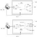
- a device under test (DUT) 200 (i.e., the wireless terminal) has a plurality of transmitting antennas 201 and the DUT 200 is placed in an anechoic chamber 301. Similarly, the number of testing antennas 302 placed in the anechoic chamber 301 is equal to the number of the transmitting antennas 201 of the DUT 200.
- the method for testing wireless performance of a wireless terminal includes the following steps.
- the antenna pattern of the plurality of transmitting antennas 201 of the DUT 200 is obtained and imported into a channel emulator 304.
- the antenna pattern is one of the important performance indicators of the antenna, and the antenna pattern includes information such as the pattern, antenna gain, and phase difference.
- a method for obtaining the antenna pattern of two transmitting antennas 201 of the DUT 200 is described below by taking a 2 ⁇ 2 MIMO wireless terminal as an example of the DUT 200.
- the antenna pattern can be obtained by testing the transmitting antennas 201 of the DUT 200 through adjusting a relative position between the DUT 200 and the testing antennas 302 placed in the anechoic chamber 301.
- the antenna pattern is obtained by testing the transmitting antennas 201 of the DUT 200.
- the DUT 200 has two transmitting antennas 201 (i.e., a transmitting antenna 2011 and a transmitting antenna 2012), and two transmitters 203 (i.e., a transmitter 2031 and a transmitter 2032). Meanwhile, a same number of testing antennas 302 as the number of the transmitting antennas 201 is selected, i.e., a testing antenna 3021 and a testing antenna 3022.
- the transmitters 203 and the transmitting antenna 201 of the DUT 200, and the testing antennas 302 are turned on.
- Gain of each transmitting antenna 201 of the DUT 200 is obtained. That is, gain of the transmitting antenna 2011 and the transmitting antenna 2012 is obtained.
- antenna gain of a transmitting antenna 201 corresponding to the turned-on transmitter 203 can be calculated by the following formula (1). That is, by turning on the transmitter 2031, the antenna gain of the transmitting antenna 2011 can be tested and calculated, and by turning on the transmitter 2032, the antenna gain of the transmitting antenna 2012 can be tested and calculated.
- G P r ⁇ PL ⁇ P o
- a transmitting power of the transmitter 203 is P o
- a total path loss (including the gain of the testing antenna 302 and link loss) of the anechoic chamber 301 is PL
- receiving power of the testing instrument is P r
- the parameters in formula 1 are in a dB format.
- the transmitting antennas 201 and the transmitters 203 of the DUT 200, and the testing antennas 302 are turned on.
- the DUT 200 and the testing antennas 302 in the anechoic chamber 301 are rotated, and a phase difference of the transmitting signals of the transmitting antennas 201 at each angle before and after the rotation can be obtained.
- an amplitude P 1 corresponding to the receiving power of the testing instrument is obtained
- an amplitude P 2 corresponding to the receiving power of the testing instrument is obtained
- an amplitude P a corresponding to the receiving power of the testing instrument is obtained.
- the antenna gain information of the transmitting antenna 2011 and the transmitting antenna 2012 of the DUT 200 is obtained through the above method, and the phase difference information between the transmitting antenna 2011 and the transmitting antenna 2012 before the rotation and the phase difference information between the transmitting antenna 2011 and the transmitting antenna 2012 after the rotation can be obtained.
- the antenna pattern of the transmitting antenna 201 is obtained according to the above information, and imported into the channel emulator 304.
- the antenna pattern of the transmitting antenna 201 of the DUT 200 and the antenna pattern of the receiving antenna 204 of the DUT 200 are the same. Therefore, the antenna pattern can also be obtained by testing the receiving antenna 204 of the DUT 200. That is, the pattern information of the receiving antenna 204 of the DUT 200 is the same as the pattern information of the transmitting antenna 201 of the DUT 200.
- the DUT 200 has two receiving antennas 204 (i.e., a receiving antenna 2041 and a receiving antenna 2042), and two receivers 205 (i.e., a receiver 2051 and a receiver 2052). Meanwhile, the same number of testing antennas 302, i.e., a testing antenna 3021 and a testing antenna 3022, as the number of the transmitting antennas 201 is selected.
- the receiver 205 and the receiving antennas 204 of the DUT 200, and the testing antenna 302 are turned on, and gain of each receiving antenna 204 of the DUT 200 is obtained, that is, the gain of the receiving antenna 2041 and the receiving antenna 2042 is obtained.
- the antenna gain G of the receiving antenna 2011 and the receiving antenna 2012 can be calculated respectively.
- the obtained gain of the receiving antenna 2041 is equal to the gain of the transmitting antenna 2011, and the obtained gain of the receiving antenna 2042 is equal to the gain of the transmitting antenna 2012.
- the parameters in formula (3) is in a dB format.
- the receiver 205 and the receiving antenna 204 of the DUT 200, and the testing antenna 302 are turned on.
- the DUT 200 and the testing antenna 302 placed in the anechoic chamber 301 are rotated, and a phase difference of the receiving signals of the receiving antennas 204 at each angle before and after the rotation is obtained.
- the phase difference information between the receiving antenna 2041 and the receiving antenna 2042 can be directly obtained by reading the reports from the receiver 2051 and the receiver 2052.
- the obtained phase difference information between the receiving antenna 2041 and the receiving antenna 2042 is equal to the phase difference information between the transmitting antenna 2011 and the transmitting antenna 2012.
- the DUT 200 and the testing antennas 302 can be rotated repeatedly according to the testing requirements.
- the antenna gain information of the transmitting antenna 2011 and the transmitting antenna 2012 of the DUT 200 is obtained, and the phase difference information between the transmitting antenna 2011 and the transmitting antenna 2012 before the rotation and the phase difference information between the transmitting antenna 2011 and the transmitting antenna 2012 after rotation are obtained, the antenna pattern of the transmitting antenna 201 is obtained according to the above information, and the obtained antenna pattern is imported into the channel emulator 304.
- a same number of testing antennas 302 in the anechoic chamber 301 as a number of the transmitting antennas 201 of the DUT 200 is selected, so that the transmitting antennas 201 of the DUT 200 transmit signals to the selected testing antennas 302 to generate a propagation channel matrix from output ports of the transmitting antennas 201 of the DUT 200 to input ports 303 of the selected testing antennas.
- a 2 ⁇ 2 MIMO wireless terminal is taken as an example of the DUT 200.
- the DUT 200 has two transmitting antennas 2011 and 2012. Meanwhile, the same number of testing antennas 302 as the number of the transmitting antennas 201 are selected, i.e., a testing antenna 3021 and a testing antenna 3022 are selected.
- the transmitting antenna 201 transmits a signal to the selected testing antenna 302, the signal sent by the transmitting antenna 201 can be received by any selected testing antenna 302.
- a signal sent by the transmitting antenna output port 2021 can be received by a testing antenna input port 3031 and a testing antenna input port 3032, and a signal sent by the transmitting antenna output port 2022 can be received by the testing antenna input port 3031 and the testing antenna input port 3032. Therefore, during the signal propagation process, a propagation channel matrix for signal propagation is generated, as illustrated by the dashed part in FIG. 7 .
- the present disclosure summarizes the law of signal propagation, and expresses the propagation channel matrix of signal propagation with the following formula (4):
- A a 11 e j ⁇ 11 a 12 e j ⁇ 12 a 21 e j ⁇ 21 a 22 e j ⁇ 22
- a xy represents an amplitude change from a y-th output port of the transmitting antennas 201 of the DUT to an x-th input port 303 of the testing antennas
- ⁇ xy represents a phase change from the y-th output port of the transmitting antennas 201 of the DUT to the x-th input port 303 of the testing antennas
- A represents the propagation channel matrix.
- an input port 303 of the selected testing antennas receives a transmitting antenna output port signal from the output port 202 of the transmitting antennas of the DUT 200 to generate a testing antenna input port signal and transmits the testing antenna input port signal to the channel emulator 304, such that the channel emulator 304 receives the testing antenna input port signal and processes the testing antenna input port signal to obtain an analog signal and send the analog signal to an analog base station 305.
- a 2 ⁇ 2 MIMO wireless terminal is taken as an example of the DUT 200.
- the DUT 200 has two transmitting antennas 201 (the transmitting antenna 2011 and the transmitting antenna 2012), the transmitting antenna 2011 has a transmitting antenna output port 2021, and the transmitting antenna 2012 has a transmitting antenna output port 2022.
- the same number of testing antennas 302 as the number of the transmitting antenna 201 are selected, that is, the testing antenna 3021 and the testing antenna 3022 are selected.
- the testing antenna 3021 has a testing antenna input port 3031 and the testing antenna 3022 has a test antenna input port 3032.
- the testing antenna input port 3031 receives the transmitting antenna output port signals x 1 and x 2 transmitted from the transmitting antenna output port 2021 and the transmitting antenna output port 2022 of the DUT 200, and generates the testing antenna input port signal Bx 1 .
- the testing antenna input port 3032 receives the transmitting antenna output port signals x 1 and x 2 from the transmitting antenna output port 2021 and the transmitting antenna output port 2022 of the DUT 200, and generates the testing antenna input port signal Bx 2 .
- the above signals are generated because the propagation channel matrix A is generated during the propagation process.
- the transmitting antenna output port signals ( x 1 , x 2 ) and the testing antenna input port signals ( Bx 1 , Bx 2 ) satisfy the following relation of formula (5).
- Bx 1 Bx 2 T A ⁇ x 1 x 2 T
- the testing antenna input port 303 send the testing antenna input port signals ( Bx 1 , Bx 2 ) to the channel emulator 304.
- the channel emulator 304 performs subsequent process on the received testing antenna input port signals ( Bx 1 , Bx 2 ), the processing steps includes the followings.
- the propagation channel matrix is unavoidable.
- the purpose of eliminating the propagation channel matrix can be achieved by loading an inverse matrix B of the propagation channel matrix.
- the channel emulator 304 loads a channel model formula operation on the signals to be calculated ( s 1 , s 2 ) based on the antenna pattern of the transmitting antennas 201 of the DUT 200 and a preset standard to obtain the analog signals ( y 1 , y 2 ).
- the antenna pattern of the transmitting antenna 201 of the DUT 200 required for the operation is obtained at block 101 and imported into the channel emulator 304.
- the preset standard includes the channel model and receiving pattern information of the base station, which are standard data known in the related art.
- the channel emulator 304 combines the imported antenna pattern of the transmitting antennas 201 of the DUT 200 and the preset standard to load the channel model formula operation on the signals to be calculated ( s 1 , s 2 ).
- the above formula indicates the signals ( x 1 , x 2 ,... x s ) from the S transmitting antenna output ports 202 of the S ⁇ U MIMO wireless terminal(i.e., the DUT 200) to the signals ( y 1 , y 2 ,... y U ) of the U ports of the analog base station 305.
- H ( t ) is a U ⁇ S channel model
- h n , u , s ( t ) is the n th element of the h u,s ( t ), which represents a propagation path of the channel model.
- the channel emulator 304 loads the above channel model formula operation on the signals to be calculated ( s 1 , s 2 ) based on the imported antenna pattern of the transmitting antennas 201 of the DUT 200 and the preset standard to obtain the analog signals ( y 1 , y 2 ).
- the analog signals ( y 1 , y 2 ) is transmitted to the analog base station 305.
- a 2 ⁇ 2 MIMO wireless terminal is taken as an example of the DUT 200.
- the DUT 200 has two transmitting antennas 201 (the transmitting antenna 2011 and the transmitting antenna 2012), the transmitting antenna 2011 has a transmitting antenna output port 2021, and the transmitting antenna 2012 has a transmitting antenna output port 2022. Meanwhile, the same number of testing antennas 302 as the number of the transmitting antennas 201 are selected, that is, the testing antenna 3021 and the testing antenna 3022 are selected.
- the testing antenna 3021 has a testing antenna input port 3031 and the testing antenna 3022 has a test antenna input port 3032.
- the method for testing wireless performance of a wireless terminal further includes the following steps. As illustrated in FIG. 11 , original transmitting antenna output port signals to be tested are ( x 1 , x 2 ), but the DUT 200 first loads the transmitting antenna output port signals with an inverse matrix C of the propagation channel matrix before the signals are generated, and then actual transmitting antenna output port signals are ( Tx 1 , Tx 2 ).
- the testing antenna input port 3031 receives the transmitting antenna output port signals Tx 1 and Tx 2 transmitted by the transmitting antenna output port 2021 and the transmitting antenna output port 2022, and a testing antenna input port signal Si is generated under effect of the propagation channel matrix A.
- the testing antenna input port 3032 receives the transmitting antenna output port signals Tx 1 and Tx 2 transmitted by the transmitting antenna output port 2021 and the transmitting antenna output port 2022, and a testing antenna input port signal S 2 is generated under the effect of the propagation channel matrix A.
- the propagation channel matrix is unavoidable, so the purpose of eliminating the propagation channel matrix can be achieved by loading the inverse matrix of the propagation channel matrix to the transmitted signals before the signals are transmitted.
- the inverse matrix C of the propagation channel matrix and the aforementioned inverse matrix B of the propagation channel matrix may be the same inverse matrix of the propagation channel matrix, or may be different inverse matrixes of the propagation channel matrix, such as a left inverse matrix and a right inverse matrix of the propagation channel matrix, respectively.
- the testing antenna input port 303 sends the testing antenna input port signals ( s 1 , s 2 ) to the channel emulator 304.
- the channel emulator 304 receives the testing antenna input port signals ( s 1 , s 2 ) and performs subsequent processing on the signal.
- the subsequent processing includes the followings.
- the channel emulator 304 loads a channel model formula operation on the signals to be calculated ( s 1 , s 2 ) based on the imported antenna pattern of the transmitting antennas 201 of the DUT 200 and a preset standard to obtain the analog signals ( y 1 , y 2 ).
- the antenna pattern of the transmitting antennas 201 of the DUT 200 required for the operation is obtained at block 101 and imported into the channel emulator 304.
- the preset standards include a channel model and base station receiving pattern information, which are standard data known in the related art.
- the channel emulator 304 combines the imported antenna pattern of the transmitting antennas 201 of the DUT 200 and the preset standard to load the channel model formula operation on the signals to be calculated ( s 1 , s 2 ).
- the related channel model operation formula includes formulas (7)-(9). The related formulas are not repeated here.
- the analog signal ( y 1 , y 2 ) is transmitted to the analog base station 305.
- the two methods can be summarized as follows.
- the former is that the testing antenna input port 303 receives the transmitting antenna output port signals ( x 1 , x 2 ) and generates the testing antenna input port signals ( Bx 1 ,Bx 2 ), the channel emulator 304 loads the inverse matrix of the propagation channel matrix on the testing antenna input port signals ( Bx 1 , Bx 2 ) to obtain the signals to be calculated ( s 1 , s 2 ) and loads the channel model formula operation on the signal to obtain the analog signals ( y 1 , y 2 ).
- the DUT 200 loads the inverse matrix of the propagation channel matrix on the transmitting antenna output port signals ( x 1 , x 2 ) that needs to be tested to obtain the actual transmitting antenna output port signals ( Tx 1 , Tx 2 ), the testing antenna input port 303 receives the actual transmitting antenna output port signals ( Tx 1 , Tx 2 ) and generates the testing antenna input port signals ( s 1 , s 2 ), the channel emulator 304 loads the channel module formula operation on the testing antenna input port signals ( s 1 , s 2 ) to obtain the analog signals ( y 1 , y 2 ).
- the step of loading the inverse matrix of the propagation channel matrix is after the DUT transmits the signal in one method, and is before the DUT transmits the signal in another method, but the analog signals ( y 1 , y 2 ) obtained by the two are identical.
- the analog base station 305 receives the analog signals ( y 1 , y 2 ) and performs a throughput test to implement an uplink wireless performance test on the DUT 200.
- the analog signals ( y 1 , y 2 ) received by the analog base station 305 fully complies with MIMO OTA test requirements of the channel model.
- This method achieves uplink wireless performance testing of the MIMO wireless device.
- This method is advanced and can implement uplink MIMO throughput test in a common SISO anechoic chamber.
- the present disclosure provides a new method and system for testing uplink wireless performance of the wireless terminal, which can ensure accuracy and convenience of the test, and are simple to implement and low in cost.
- the present disclosure has the following advantages.
- the system for testing wireless performance of a wireless terminal includes an anechoic chamber 301, testing antennas 302, a channel emulator 304, and an analog base station 305.
- the anechoic chamber 301 is configured to place the testing antennas and a device under test.
- the testing antennas 302 has a testing antenna input port 303, and are configured to receive a transmitting antenna output port signal transmitted by a transmitting antenna output port 202 of a transmitting antenna 202 of the device under test 200 via the testing antenna input port 303.
- the channel emulator 304 is configured to receive a testing antenna input port signal transmitted by a testing antenna input port 303 of a selected testing antenna 302, process the signal based on antenna pattern of the transmitting antenna 201 of the device under test 200 and a preset standard to obtain an analog signal, and send the analog signal to the analog base station 305.
- the analog base station 305 is configured to receive the analog signal, perform a throughput test, to implement an uplink wireless performance test of the device under test 200.
- the channel emulator 304 and the analog base station 305 may be integrated in one testing instrument, or may constitute a plurality of testing instruments respectively. As illustrated in FIG. 12 , the channel emulator 304 and the analog base station 305 respectively constitute a plurality of testing instruments. As illustrated in FIGs. 5 and 6 , the channel emulator 304 and the analog base station 305 are integrated in one test instrument.
- the DUT 200 is configured to load an inverse matrix of a propagation channel matrix on an original transmitting signal to get a loaded signal, and transmit the loaded signal by the transmitting antenna 202 of the DUT 200.
- the channel emulator 304 is configured to receive a signal from the testing antennas 302, process the signal to obtain an analog signal by calculating the received signal based on an antenna pattern of the transmitting antennas 202 of the DUT 200 and a preset channel model.
- the present disclosure provides a new method and system for testing uplink wireless performance of the wireless terminal, which can ensure accuracy and convenience of the test, and are simple to implement and low in cost.
- the present disclosure has the following advantages.
Landscapes
- Physics & Mathematics (AREA)
- Engineering & Computer Science (AREA)
- Computer Networks & Wireless Communication (AREA)
- Signal Processing (AREA)
- Electromagnetism (AREA)
- Spectroscopy & Molecular Physics (AREA)
- General Physics & Mathematics (AREA)
- Monitoring And Testing Of Transmission In General (AREA)
- Mobile Radio Communication Systems (AREA)
- Variable-Direction Aerials And Aerial Arrays (AREA)
Claims (11)
- Verfahren zum Testen einer drahtlosen Leistung eines drahtlosen Endgeräts, wobei das drahtlose Endgerät als ein Prüfling, DUT, konfiguriert ist, der DUT eine Vielzahl von Sendeantennen aufweist und in einem schalltoten Raum platziert ist, und das Verfahren umfasst:Erhalten (101) eines Antennenmusters der Vielzahl der Sendeantennen des DUT und Importieren des Antennenmusters in einen Kanalemulator;Auswählen (102) einer gleichen Anzahl von Testantennen in dem schalltoten Raum wie eine Anzahl der Sendeantennen des DUT, sodass die Sendeantennen des DUT Signale an die ausgewählten Testantennen senden, und Erzeugen einer Ausbreitungskanalmatrix zwischen Ausgangsanschlüssen der Sendeantennen des DUT und Eingangsanschlüssen der ausgewählten Testantennen;Laden einer inversen Matrix der Ausbreitungskanalmatrix auf ursprüngliche Sendesignale, um geladene Signale zu erlangen;Senden, durch die Sendeantennen des DUT, der geladenen Signale an die ausgewählten Testantennen;Empfangen (103), durch die ausgewählten Testantennen, von Sendeantennenausgangsanschlusssignalen von den Sendeantennen des DUT, um Testantenneneingangsanschlusssignale zu erzeugen, und Übertragen der Testantenneneingangsanschlusssignale an den Kanalemulator, wobei der Kanalemulator die Testantenneneingangsanschlusssignale empfängt und verarbeitet, um ein analoges Signal zu erzeugen, und das analoge Signal an eine analoge Basisstation überträgt; undEmpfangen (104), durch die analoge Basisstation, des analogen Signals und Durchführen eines Durchsatztests, um einen Test einer drahtlosen Uplink-Leistung des DUT zu erhalten.
- Verfahren nach Anspruch 1, wobei das Antennenmuster der Sendeantennen Antennengewinninformationen und Phasendifferenzinformationen umfasst.
- Verfahren nach Anspruch 1 oder 2, das Erhalten des Antennenmusters der Sendeantennen umfassend:
Testen der Sendeantennen des DUT und Erhalten des Antennenmusters. - Verfahren nach einem der Ansprüche 1 bis 3, das Erhalten des Antennenmusters der Sendeantennen umfassend:
Testen einer Empfangsantenne des DUT und Erhalten des Antennenmusters, wobei das Antennenmuster der Sendeantenne mit dem Antennenmuster der Empfangsantenne für ein System identisch ist, das Signale auf der gleichen Frequenz sendet und empfängt. - Verfahren nach einem der Ansprüche 1 bis 4, wobei die Sendeantennenausgangsanschlusssignale von den Sendeantennen des DUT durch beliebige ausgewählte Testantennen empfangen werden können.
- Verfahren nach einem der Ansprüche 1 bis 5, wobei, wenn der DUT ein drahtloses 2×2-MlMO-Endgerät ist, die Ausbreitungskanalmatrix ist:

- Verfahren nach einem der Ansprüche 1 bis 6, wobei die ursprünglichen Sendesignale, die geladenen Signale, die Sendeantennenausgangsanschlusssignale, die durch die ausgewählten Testantennen empfangen werden, die Ausbreitungskanalmatrix und die inverse Matrix der Ausbreitungskanalmatrix eine folgende Beziehung erfüllen:


- Verfahren nach Anspruch 7, wobei ein Verarbeiten, durch den Kanalemulator, der Testantenneneingangsanschlusssignale, um das analoge Signal zu erzeugen, und das Übertragen des analogen Signals an die analoge Basisstation umfasst:Berechnen, durch den Kanalemulator, der Testantenneneingangsanschlusssignale basierend auf dem Antennenmuster der Sendeantennen des DUT und einem voreingestellten Kanalmodell, um das analoge Signal zu erhalten; undÜbertragen des analogen Signals an die analoge Basisstation.
- System zum Testen der drahtlosen Leistung eines drahtlosen Endgeräts, umfassend einen schalltoten Raum (301), Testantennen (302), einen Kanalemulator (304) und eine analoge Basisstation (305), wobeider schalltote Raum (301) konfiguriert ist, um die Testantennen (302) und einen Prüfling, DUT, (200) zu platzieren;die Testantennen (302) konfiguriert sind, um Sendeantennenausgangsanschlusssignale von Sendeantennen (201) des DUT (200) zu empfangen, wobei eine Ausbreitungskanalmatrix zwischen Ausgangsanschlüssen der Sendeantennen (201) des DUT (200) und Eingangsanschlüssen der Testantennen (302) während eines Signalausbreitungsprozesses erzeugt wird;der Kanalemulator (304) konfiguriert ist, um Testantenneneingangsanschlusssignale von den Testantennen (302) zu empfangen, die Testantenneneingangsanschlusssignale zu verarbeiten, um ein analoges Signal zu erhalten, und das analoge Signal an die analoge Basisstation (305) zu übertragen; unddie analoge Basisstation (305) konfiguriert ist, um das analoge Signal zu empfangen, einen Durchsatztest durchzuführen, um einen Test der drahtlosen Uplink-Leistung des DUT (200) zu erhalten,das System dadurch gekennzeichnet ist, dass der DUT (200) konfiguriert ist, um eine inverse Matrix der Ausbreitungskanalmatrix auf ein ursprüngliches Sendesignal zu laden, um ein geladenes Signal zu erhalten, und das geladene Signal durch die Sendeantennen (201) des DUT (200) zu senden.
- System nach Anspruch 9, wobei der Kanalemulator (304) und die analoge Basisstation (305) in ein Testinstrument integriert sind beziehungsweise eine Vielzahl von Testinstrumenten bilden.
- System nach einem der Ansprüche 9 bis 10, wobei der Kanalemulator (304) konfiguriert ist, um die Testantenneneingangsanschlusssignale von den Testantennen (302) zu empfangen, die Testantenneneingangsanschlusssignale zu verarbeiten, um ein analoges Signal durch Berechnen der empfangenen Testantenneneingangsanschlusssignale basierend auf einem Antennenmuster der Sendeantennen (201) des DUT (200) und einem voreingestellten Kanalmodell zu erhalten.
Applications Claiming Priority (2)
| Application Number | Priority Date | Filing Date | Title |
|---|---|---|---|
| CN201811417925.0A CN111224696B (zh) | 2018-11-26 | 2018-11-26 | 无线终端的无线性能测试方法及系统 |
| PCT/CN2019/115544 WO2020108239A1 (zh) | 2018-11-26 | 2019-11-05 | 无线终端的无线性能测试方法及系统 |
Publications (3)
| Publication Number | Publication Date |
|---|---|
| EP3890199A1 EP3890199A1 (de) | 2021-10-06 |
| EP3890199A4 EP3890199A4 (de) | 2022-08-24 |
| EP3890199B1 true EP3890199B1 (de) | 2024-10-23 |
Family
ID=70831974
Family Applications (1)
| Application Number | Title | Priority Date | Filing Date |
|---|---|---|---|
| EP19891243.8A Active EP3890199B1 (de) | 2018-11-26 | 2019-11-05 | Verfahren und system zur prüfung der drahtlosen leistung eines drahtlosen endgeräts |
Country Status (6)
| Country | Link |
|---|---|
| US (1) | US11962357B2 (de) |
| EP (1) | EP3890199B1 (de) |
| JP (1) | JP7470686B2 (de) |
| KR (1) | KR102436859B1 (de) |
| CN (1) | CN111224696B (de) |
| WO (1) | WO2020108239A1 (de) |
Families Citing this family (13)
| Publication number | Priority date | Publication date | Assignee | Title |
|---|---|---|---|---|
| JP6723424B1 (ja) * | 2019-06-21 | 2020-07-15 | 株式会社横須賀テレコムリサーチパーク | 送受信方法および送受信システム |
| CN112543068B (zh) * | 2019-09-23 | 2022-06-10 | 华为机器有限公司 | 测试方法、装置及系统 |
| CN112583502B (zh) * | 2019-09-27 | 2022-06-10 | 维沃移动通信有限公司 | 一种探头天线确定方法及装置 |
| CN112383660B (zh) * | 2020-11-02 | 2024-04-02 | 西安闻泰电子科技有限公司 | 智能终端的吞吐率测试方法、装置、存储介质和终端 |
| CN115225173B (zh) * | 2022-07-28 | 2023-09-01 | 联宝(合肥)电子科技有限公司 | 一种无线连接性能测试方法、装置、电子设备及存储介质 |
| CN115412185A (zh) * | 2022-08-23 | 2022-11-29 | 太仓市同维电子有限公司 | 一种无线性能自动化测试系统及测试方法、电子设备、服务器 |
| CN115290991B (zh) * | 2022-10-09 | 2022-12-30 | 荣耀终端有限公司 | 天线测试方法、装置、系统、信道仿真仪及可读存储介质 |
| CN115967456B (zh) * | 2022-12-23 | 2025-06-20 | 广电计量检测集团股份有限公司 | 一种无线局域网中精密动作识别器的相位偏移检测方法 |
| CN116112101B (zh) * | 2022-12-27 | 2026-01-16 | 深圳市通用测试系统有限公司 | 无线设备的空中辐射测试系统、方法和测试仪 |
| CN116232494B (zh) * | 2023-03-01 | 2026-03-20 | 北京中科国技信息系统有限公司 | 多天线终端的性能测试方法及装置 |
| CN116660634A (zh) * | 2023-04-25 | 2023-08-29 | 浙江大学 | 用于mimo天线ota测试的电磁屏蔽室测试方法 |
| CN117639969B (zh) * | 2023-12-13 | 2024-07-09 | 广州通则康威科技股份有限公司 | 一种蜂窝网络终端自动测试方法、终端及系统 |
| CN117896020B (zh) * | 2024-01-25 | 2024-06-18 | 北京雷格讯电子股份有限公司 | 一种微波收发通信系统的测试方法及测试系统 |
Family Cites Families (48)
| Publication number | Priority date | Publication date | Assignee | Title |
|---|---|---|---|---|
| US8194770B2 (en) * | 2002-08-27 | 2012-06-05 | Qualcomm Incorporated | Coded MIMO systems with selective channel inversion applied per eigenmode |
| US8134976B2 (en) * | 2002-10-25 | 2012-03-13 | Qualcomm Incorporated | Channel calibration for a time division duplexed communication system |
| US7965986B2 (en) * | 2006-06-07 | 2011-06-21 | Ets-Lindgren, L.P. | Systems and methods for over-the-air testing of wireless systems |
| DE102008013011A1 (de) * | 2008-03-07 | 2009-09-10 | Rohde & Schwarz Gmbh & Co. Kg | Verfahren zur Generierung von Mehrantennensignalen |
| US20090268678A1 (en) | 2008-04-24 | 2009-10-29 | Fujitsu Limited | Method and apparatus for automatic gain control in a mobile orthogonal frequency division multiple access (ofdma) network |
| DE102008055759A1 (de) * | 2008-11-04 | 2010-05-06 | Rohde & Schwarz Gmbh & Co. Kg | Verfahren und Vorrichtung zum Testen eines Mobilfunkgeräts mittels statischer Kanalsimulation |
| US8913963B2 (en) * | 2008-11-24 | 2014-12-16 | Unwired Planet, Llc | Method and device in over-the-air test environment |
| JP5488016B2 (ja) * | 2009-03-30 | 2014-05-14 | 富士通株式会社 | 無線通信方法、無線通信システム及び無線通信装置 |
| CN102148648B (zh) * | 2010-02-05 | 2015-04-01 | 中兴通讯股份有限公司 | 多天线系统中的空间射频性能测试方法及系统 |
| CN102158873A (zh) * | 2010-02-12 | 2011-08-17 | 中兴通讯股份有限公司 | 基于多天线系统的空间射频性能测试方法及系统 |
| US8718122B2 (en) * | 2010-02-18 | 2014-05-06 | Azimuth Systems, Inc. | Testing performance of a wireless device |
| US8793093B2 (en) * | 2010-04-29 | 2014-07-29 | Apple Inc. | Tools for design and analysis of over-the-air test systems with channel model emulation capabilities |
| KR101442942B1 (ko) * | 2010-05-24 | 2014-11-03 | 아니테 텔레콤즈 오와이 | Ota 테스트 |
| US8912963B2 (en) * | 2010-10-20 | 2014-12-16 | Apple Inc. | System for testing multi-antenna devices using bidirectional faded channels |
| US20120100813A1 (en) * | 2010-10-20 | 2012-04-26 | Mow Matt A | System for testing multi-antenna devices using bidirectional faded channels |
| JP5650850B2 (ja) * | 2010-12-28 | 2015-01-07 | アナイト・テレコムズ・オサケユキテュア | オーバー・ジ・エアー試験 |
| US8682638B2 (en) * | 2011-06-30 | 2014-03-25 | Octoscope, Inc. | Channel emulator system and method |
| US8774729B2 (en) * | 2012-05-02 | 2014-07-08 | Litepoint Corporation | System and method for synchronized triggering of test equipment for testing MIMO transceivers |
| US20130303089A1 (en) * | 2012-05-11 | 2013-11-14 | Apple Inc. | Uplink and/or Downlink Testing of Wireless Devices in a Reverberation Chamber |
| KR101997954B1 (ko) * | 2012-09-27 | 2019-07-08 | 키사이트 테크놀로지스 싱가포르 (세일즈) 피티이. 엘티디. | 무선 채널 에뮬레이션 |
| US8995926B2 (en) * | 2012-09-27 | 2015-03-31 | Apple Inc. | Methods and apparatus for performing coexistence testing for multi-antenna electronic devices |
| US9107098B2 (en) * | 2012-10-08 | 2015-08-11 | Netgear, Inc. | Near-field MIMO wireless test systems, structures, and processes |
| CN103856272B (zh) | 2012-12-03 | 2017-09-05 | 深圳市通用测试系统有限公司 | Mimo无线终端的无线性能测试方法 |
| US8824588B2 (en) * | 2012-12-10 | 2014-09-02 | Netgear, Inc. | Near-field MIMO wireless transmit power measurement test systems, structures, and processes |
| US20150017928A1 (en) * | 2013-07-09 | 2015-01-15 | Azimuth Systems, Inc. | Over-the-air testing of wireless devices using log files |
| GB2536539B (en) * | 2015-01-19 | 2017-07-19 | Keysight Technologies Inc | System and method for testing multi-user, multi-input/multi-output systems |
| US10601659B2 (en) * | 2015-01-29 | 2020-03-24 | Telefonaktiebolaget Lm Ericsson (Publ) | Methods to signal current MIMO RX antenna configuration status |
| US9660739B2 (en) * | 2015-02-09 | 2017-05-23 | Spirent Communications, Inc. | System and methods of testing adaptive antennas |
| CN105743553A (zh) * | 2016-01-26 | 2016-07-06 | 北京邮电大学 | 一种多天线移动终端的上行性能测试系统及方法 |
| US9742508B1 (en) * | 2016-02-26 | 2017-08-22 | Keysight Technologies, Inc. | Systems and methods for calibrating multiple input, multiple output (MIMO) test systems and for using the calibrated MIMO test systems to test mobile devices |
| EP3410768B1 (de) * | 2016-03-31 | 2022-07-27 | Huawei Technologies Co., Ltd. | Signalübertragungsverfahren für endgerätevorrichtung sowie endgerätevorrichtung |
| CN109075839B (zh) * | 2016-04-26 | 2021-10-12 | 梁平 | 用于具有空中传输连接的大型mimo信道仿真器的空中传输信道状态信息获取 |
| US10244411B2 (en) * | 2016-06-14 | 2019-03-26 | Spirent Communications, Inc. | Over the air testing for massive MIMO arrays |
| CN107543978B (zh) * | 2016-06-23 | 2021-08-24 | 是德科技股份有限公司 | 经由ota辐射测试系统标定出mimo中辐射通道矩阵的系统和方法 |
| US10601695B2 (en) * | 2016-09-01 | 2020-03-24 | Keysight Technologies, Inc. | Systems and methods for radio channel emulation of a multiple input multiple output (MIMO) wireless link |
| US9866294B1 (en) * | 2016-09-19 | 2018-01-09 | Rohde & Schwarz Gmbh & Co. Kg | Method for testing a multiple-input and multiple-output device and test system |
| CN108234036B (zh) * | 2016-12-14 | 2020-05-12 | 深圳市通用测试系统有限公司 | Mimo无线终端的无线性能测试方法 |
| US10033473B1 (en) * | 2017-01-23 | 2018-07-24 | Keysight Technologies, Inc. | Systems and methods for performing multiple input, multiple output (MIMO) over-the-air testing |
| JP7088631B2 (ja) | 2017-03-06 | 2022-06-21 | 株式会社Nttドコモ | 送受信装置 |
| CN108574539B (zh) * | 2017-03-08 | 2021-01-15 | 深圳市通用测试系统有限公司 | 基于mimo无线终端测试的信号生成方法和装置 |
| US11329364B2 (en) * | 2017-03-15 | 2022-05-10 | Sony Mobile Communications Inc. | Communication apparatus |
| CN108966264B (zh) * | 2017-05-22 | 2023-05-02 | 是德科技股份有限公司 | 对大规模多入多出无线系统执行空中测试的系统和方法 |
| CN111149006B (zh) * | 2017-08-23 | 2022-08-02 | 弗劳恩霍夫应用研究促进协会 | 基于波束成形的多天线设备的空中校准和测试 |
| US10110326B1 (en) * | 2017-09-30 | 2018-10-23 | Keysight Technologies, Inc. | Multi-probe anechoic chamber (MPAC) over-the-air (OTA) test system having a radio channel (RC) emulator that has a dynamically-variable channel model, and methods |
| US10313034B2 (en) * | 2017-10-12 | 2019-06-04 | Spirent Communications, Inc. | Massive MIMO array testing using a programmable phase matrix and channel emulator |
| CN108307421B (zh) * | 2018-01-12 | 2020-04-21 | 深圳市通用测试系统有限公司 | 无线终端的测量方法、计算机可读存储介质、装置及系统 |
| US20190253158A1 (en) * | 2018-02-15 | 2019-08-15 | Rohde & Schwarz Gmbh & Co. Kg | Measurement system and method for operating a measurement system |
| FI128609B2 (en) * | 2018-10-12 | 2026-01-14 | Orbis Systems Oy | Arrangement and procedure for testing a 4.5G or 5G base station |
-
2018
- 2018-11-26 CN CN201811417925.0A patent/CN111224696B/zh active Active
-
2019
- 2019-11-05 KR KR1020217019827A patent/KR102436859B1/ko active Active
- 2019-11-05 JP JP2021529865A patent/JP7470686B2/ja active Active
- 2019-11-05 EP EP19891243.8A patent/EP3890199B1/de active Active
- 2019-11-05 WO PCT/CN2019/115544 patent/WO2020108239A1/zh not_active Ceased
-
2021
- 2021-05-26 US US17/330,936 patent/US11962357B2/en active Active
Also Published As
| Publication number | Publication date |
|---|---|
| EP3890199A4 (de) | 2022-08-24 |
| EP3890199A1 (de) | 2021-10-06 |
| CN111224696B (zh) | 2021-04-20 |
| CN111224696A (zh) | 2020-06-02 |
| KR102436859B1 (ko) | 2022-08-26 |
| JP2022509828A (ja) | 2022-01-24 |
| JP7470686B2 (ja) | 2024-04-18 |
| US11962357B2 (en) | 2024-04-16 |
| KR20210093346A (ko) | 2021-07-27 |
| WO2020108239A1 (zh) | 2020-06-04 |
| US20210314075A1 (en) | 2021-10-07 |
Similar Documents
| Publication | Publication Date | Title |
|---|---|---|
| EP3890199A1 (de) | Verfahren und system zur prüfung der drahtlosen leistung eines drahtlosen endgeräts | |
| US10684318B1 (en) | System and method for testing analog beamforming device | |
| KR101706882B1 (ko) | 무선 단말기의 성능을 테스팅하기 위한 방법 및 디바이스 | |
| CN109936398B (zh) | 用于测试具有波束成形电路的无线装置的系统和方法 | |
| US9209914B2 (en) | Method and apparatus for virtual desktop OTA | |
| US10935583B2 (en) | Measurement system and method for performing test measurements | |
| US9316714B2 (en) | Test station for wireless devices and methods for calibration thereof | |
| JP6464151B2 (ja) | 無線試験信号を用いて無線周波数無線信号送受信機を試験するためのシステム及び方法 | |
| US10103823B1 (en) | Radio channel emulator having a dynamically-variable channel model for use in testing base stations and user equipment (UE) that perform analog beam forming | |
| US12013424B2 (en) | Antenna test system and a method for testing an antenna | |
| CN102158873A (zh) | 基于多天线系统的空间射频性能测试方法及系统 | |
| CN114024641B (zh) | 基于实测数据的太赫兹mimo信道建模方法和系统 | |
| KR20150132121A (ko) | 무선 테스트 신호를 이용하여 무선 주파수 무선 신호 트랜시버를 테스트하는 시스템 및 방법 | |
| CN101667873A (zh) | 一种多天线信道环境下接收机射频性能的测试方法和系统 | |
| CN105264391A (zh) | 使用无线测试信号测试射频无线信号收发器的系统和方法 | |
| CN105264390A (zh) | 使用无线测试信号测试射频无线信号收发器的系统和方法 | |
| Fan et al. | Wireless cable testing for MIMO radios: A compact and cost-effective 5G radio performance test solution | |
| CN102158291A (zh) | 基于多天线系统的空间射频性能测试方法及系统 | |
| CN116112101B (zh) | 无线设备的空中辐射测试系统、方法和测试仪 | |
| Mei et al. | OTA throughput prediction of MIMO antennas for wireless devices by simulated realistic channel model | |
| CN108307421B (zh) | 无线终端的测量方法、计算机可读存储介质、装置及系统 | |
| Berlt | Over-the-air testing of automotive antennas and wireless links in the installed state on the basis of LTE downlink communication parameters | |
| Rumney et al. | The need for spatial channel emulation to evaluate mmwave UE and base station performance | |
| HK1181202B (en) | Test station for wireless devices and methods for calibration thereof |
Legal Events
| Date | Code | Title | Description |
|---|---|---|---|
| STAA | Information on the status of an ep patent application or granted ep patent |
Free format text: STATUS: THE INTERNATIONAL PUBLICATION HAS BEEN MADE |
|
| PUAI | Public reference made under article 153(3) epc to a published international application that has entered the european phase |
Free format text: ORIGINAL CODE: 0009012 |
|
| STAA | Information on the status of an ep patent application or granted ep patent |
Free format text: STATUS: REQUEST FOR EXAMINATION WAS MADE |
|
| 17P | Request for examination filed |
Effective date: 20210618 |
|
| AK | Designated contracting states |
Kind code of ref document: A1 Designated state(s): AL AT BE BG CH CY CZ DE DK EE ES FI FR GB GR HR HU IE IS IT LI LT LU LV MC MK MT NL NO PL PT RO RS SE SI SK SM TR |
|
| DAV | Request for validation of the european patent (deleted) | ||
| DAX | Request for extension of the european patent (deleted) | ||
| A4 | Supplementary search report drawn up and despatched |
Effective date: 20220721 |
|
| RIC1 | Information provided on ipc code assigned before grant |
Ipc: H04B 17/391 20150101ALI20220715BHEP Ipc: H04B 17/16 20150101ALI20220715BHEP Ipc: G01R 29/10 20060101ALI20220715BHEP Ipc: H04B 17/15 20150101ALI20220715BHEP Ipc: H04B 17/00 20150101ALI20220715BHEP Ipc: H04B 7/0413 20170101AFI20220715BHEP |
|
| STAA | Information on the status of an ep patent application or granted ep patent |
Free format text: STATUS: EXAMINATION IS IN PROGRESS |
|
| 17Q | First examination report despatched |
Effective date: 20231024 |
|
| GRAP | Despatch of communication of intention to grant a patent |
Free format text: ORIGINAL CODE: EPIDOSNIGR1 |
|
| STAA | Information on the status of an ep patent application or granted ep patent |
Free format text: STATUS: GRANT OF PATENT IS INTENDED |
|
| GRAS | Grant fee paid |
Free format text: ORIGINAL CODE: EPIDOSNIGR3 |
|
| INTG | Intention to grant announced |
Effective date: 20240820 |
|
| GRAA | (expected) grant |
Free format text: ORIGINAL CODE: 0009210 |
|
| STAA | Information on the status of an ep patent application or granted ep patent |
Free format text: STATUS: THE PATENT HAS BEEN GRANTED |
|
| AK | Designated contracting states |
Kind code of ref document: B1 Designated state(s): AL AT BE BG CH CY CZ DE DK EE ES FI FR GB GR HR HU IE IS IT LI LT LU LV MC MK MT NL NO PL PT RO RS SE SI SK SM TR |
|
| REG | Reference to a national code |
Ref country code: GB Ref legal event code: FG4D |
|
| REG | Reference to a national code |
Ref country code: CH Ref legal event code: EP |
|
| REG | Reference to a national code |
Ref country code: DE Ref legal event code: R096 Ref document number: 602019060943 Country of ref document: DE |
|
| REG | Reference to a national code |
Ref country code: IE Ref legal event code: FG4D |
|
| P01 | Opt-out of the competence of the unified patent court (upc) registered |
Free format text: CASE NUMBER: APP_58942/2024 Effective date: 20241029 |
|
| REG | Reference to a national code |
Ref country code: LT Ref legal event code: MG9D |
|
| REG | Reference to a national code |
Ref country code: NL Ref legal event code: MP Effective date: 20241023 |
|
| REG | Reference to a national code |
Ref country code: AT Ref legal event code: MK05 Ref document number: 1735691 Country of ref document: AT Kind code of ref document: T Effective date: 20241023 |
|
| PG25 | Lapsed in a contracting state [announced via postgrant information from national office to epo] |
Ref country code: NL Free format text: LAPSE BECAUSE OF FAILURE TO SUBMIT A TRANSLATION OF THE DESCRIPTION OR TO PAY THE FEE WITHIN THE PRESCRIBED TIME-LIMIT Effective date: 20241023 |
|
| PG25 | Lapsed in a contracting state [announced via postgrant information from national office to epo] |
Ref country code: NL Free format text: LAPSE BECAUSE OF FAILURE TO SUBMIT A TRANSLATION OF THE DESCRIPTION OR TO PAY THE FEE WITHIN THE PRESCRIBED TIME-LIMIT Effective date: 20241023 |
|
| PG25 | Lapsed in a contracting state [announced via postgrant information from national office to epo] |
Ref country code: IS Free format text: LAPSE BECAUSE OF FAILURE TO SUBMIT A TRANSLATION OF THE DESCRIPTION OR TO PAY THE FEE WITHIN THE PRESCRIBED TIME-LIMIT Effective date: 20250223 Ref country code: HR Free format text: LAPSE BECAUSE OF FAILURE TO SUBMIT A TRANSLATION OF THE DESCRIPTION OR TO PAY THE FEE WITHIN THE PRESCRIBED TIME-LIMIT Effective date: 20241023 Ref country code: PT Free format text: LAPSE BECAUSE OF FAILURE TO SUBMIT A TRANSLATION OF THE DESCRIPTION OR TO PAY THE FEE WITHIN THE PRESCRIBED TIME-LIMIT Effective date: 20250224 |
|
| PG25 | Lapsed in a contracting state [announced via postgrant information from national office to epo] |
Ref country code: FI Free format text: LAPSE BECAUSE OF FAILURE TO SUBMIT A TRANSLATION OF THE DESCRIPTION OR TO PAY THE FEE WITHIN THE PRESCRIBED TIME-LIMIT Effective date: 20241023 |
|
| PG25 | Lapsed in a contracting state [announced via postgrant information from national office to epo] |
Ref country code: BG Free format text: LAPSE BECAUSE OF FAILURE TO SUBMIT A TRANSLATION OF THE DESCRIPTION OR TO PAY THE FEE WITHIN THE PRESCRIBED TIME-LIMIT Effective date: 20241023 |
|
| PG25 | Lapsed in a contracting state [announced via postgrant information from national office to epo] |
Ref country code: ES Free format text: LAPSE BECAUSE OF FAILURE TO SUBMIT A TRANSLATION OF THE DESCRIPTION OR TO PAY THE FEE WITHIN THE PRESCRIBED TIME-LIMIT Effective date: 20241023 |
|
| PG25 | Lapsed in a contracting state [announced via postgrant information from national office to epo] |
Ref country code: NO Free format text: LAPSE BECAUSE OF FAILURE TO SUBMIT A TRANSLATION OF THE DESCRIPTION OR TO PAY THE FEE WITHIN THE PRESCRIBED TIME-LIMIT Effective date: 20250123 |
|
| PG25 | Lapsed in a contracting state [announced via postgrant information from national office to epo] |
Ref country code: AT Free format text: LAPSE BECAUSE OF FAILURE TO SUBMIT A TRANSLATION OF THE DESCRIPTION OR TO PAY THE FEE WITHIN THE PRESCRIBED TIME-LIMIT Effective date: 20241023 Ref country code: GR Free format text: LAPSE BECAUSE OF FAILURE TO SUBMIT A TRANSLATION OF THE DESCRIPTION OR TO PAY THE FEE WITHIN THE PRESCRIBED TIME-LIMIT Effective date: 20250124 Ref country code: LV Free format text: LAPSE BECAUSE OF FAILURE TO SUBMIT A TRANSLATION OF THE DESCRIPTION OR TO PAY THE FEE WITHIN THE PRESCRIBED TIME-LIMIT Effective date: 20241023 |
|
| PG25 | Lapsed in a contracting state [announced via postgrant information from national office to epo] |
Ref country code: PL Free format text: LAPSE BECAUSE OF FAILURE TO SUBMIT A TRANSLATION OF THE DESCRIPTION OR TO PAY THE FEE WITHIN THE PRESCRIBED TIME-LIMIT Effective date: 20241023 |
|
| PG25 | Lapsed in a contracting state [announced via postgrant information from national office to epo] |
Ref country code: RS Free format text: LAPSE BECAUSE OF FAILURE TO SUBMIT A TRANSLATION OF THE DESCRIPTION OR TO PAY THE FEE WITHIN THE PRESCRIBED TIME-LIMIT Effective date: 20250123 |
|
| REG | Reference to a national code |
Ref country code: CH Ref legal event code: PL |
|
| PG25 | Lapsed in a contracting state [announced via postgrant information from national office to epo] |
Ref country code: SM Free format text: LAPSE BECAUSE OF FAILURE TO SUBMIT A TRANSLATION OF THE DESCRIPTION OR TO PAY THE FEE WITHIN THE PRESCRIBED TIME-LIMIT Effective date: 20241023 |
|
| PG25 | Lapsed in a contracting state [announced via postgrant information from national office to epo] |
Ref country code: MC Free format text: LAPSE BECAUSE OF FAILURE TO SUBMIT A TRANSLATION OF THE DESCRIPTION OR TO PAY THE FEE WITHIN THE PRESCRIBED TIME-LIMIT Effective date: 20241023 |
|
| PG25 | Lapsed in a contracting state [announced via postgrant information from national office to epo] |
Ref country code: DK Free format text: LAPSE BECAUSE OF FAILURE TO SUBMIT A TRANSLATION OF THE DESCRIPTION OR TO PAY THE FEE WITHIN THE PRESCRIBED TIME-LIMIT Effective date: 20241023 |
|
| PG25 | Lapsed in a contracting state [announced via postgrant information from national office to epo] |
Ref country code: LU Free format text: LAPSE BECAUSE OF NON-PAYMENT OF DUE FEES Effective date: 20241105 |
|
| REG | Reference to a national code |
Ref country code: CH Ref legal event code: PL |
|
| PG25 | Lapsed in a contracting state [announced via postgrant information from national office to epo] |
Ref country code: EE Free format text: LAPSE BECAUSE OF FAILURE TO SUBMIT A TRANSLATION OF THE DESCRIPTION OR TO PAY THE FEE WITHIN THE PRESCRIBED TIME-LIMIT Effective date: 20241023 |
|
| PG25 | Lapsed in a contracting state [announced via postgrant information from national office to epo] |
Ref country code: CH Free format text: LAPSE BECAUSE OF NON-PAYMENT OF DUE FEES Effective date: 20241130 |
|
| PG25 | Lapsed in a contracting state [announced via postgrant information from national office to epo] |
Ref country code: RO Free format text: LAPSE BECAUSE OF FAILURE TO SUBMIT A TRANSLATION OF THE DESCRIPTION OR TO PAY THE FEE WITHIN THE PRESCRIBED TIME-LIMIT Effective date: 20241023 |
|
| REG | Reference to a national code |
Ref country code: DE Ref legal event code: R097 Ref document number: 602019060943 Country of ref document: DE |
|
| PG25 | Lapsed in a contracting state [announced via postgrant information from national office to epo] |
Ref country code: SK Free format text: LAPSE BECAUSE OF FAILURE TO SUBMIT A TRANSLATION OF THE DESCRIPTION OR TO PAY THE FEE WITHIN THE PRESCRIBED TIME-LIMIT Effective date: 20241023 |
|
| PG25 | Lapsed in a contracting state [announced via postgrant information from national office to epo] |
Ref country code: CZ Free format text: LAPSE BECAUSE OF FAILURE TO SUBMIT A TRANSLATION OF THE DESCRIPTION OR TO PAY THE FEE WITHIN THE PRESCRIBED TIME-LIMIT Effective date: 20241023 |
|
| PG25 | Lapsed in a contracting state [announced via postgrant information from national office to epo] |
Ref country code: IT Free format text: LAPSE BECAUSE OF FAILURE TO SUBMIT A TRANSLATION OF THE DESCRIPTION OR TO PAY THE FEE WITHIN THE PRESCRIBED TIME-LIMIT Effective date: 20241023 |
|
| REG | Reference to a national code |
Ref country code: BE Ref legal event code: MM Effective date: 20241130 |
|
| PLBE | No opposition filed within time limit |
Free format text: ORIGINAL CODE: 0009261 |
|
| STAA | Information on the status of an ep patent application or granted ep patent |
Free format text: STATUS: NO OPPOSITION FILED WITHIN TIME LIMIT |
|
| PG25 | Lapsed in a contracting state [announced via postgrant information from national office to epo] |
Ref country code: SE Free format text: LAPSE BECAUSE OF FAILURE TO SUBMIT A TRANSLATION OF THE DESCRIPTION OR TO PAY THE FEE WITHIN THE PRESCRIBED TIME-LIMIT Effective date: 20241023 |
|
| GBPC | Gb: european patent ceased through non-payment of renewal fee |
Effective date: 20250123 |
|
| 26N | No opposition filed |
Effective date: 20250724 |
|
| PG25 | Lapsed in a contracting state [announced via postgrant information from national office to epo] |
Ref country code: GB Free format text: LAPSE BECAUSE OF NON-PAYMENT OF DUE FEES Effective date: 20250123 Ref country code: BE Free format text: LAPSE BECAUSE OF NON-PAYMENT OF DUE FEES Effective date: 20241130 |
|
| PG25 | Lapsed in a contracting state [announced via postgrant information from national office to epo] |
Ref country code: FR Free format text: LAPSE BECAUSE OF NON-PAYMENT OF DUE FEES Effective date: 20241223 |
|
| PG25 | Lapsed in a contracting state [announced via postgrant information from national office to epo] |
Ref country code: IE Free format text: LAPSE BECAUSE OF NON-PAYMENT OF DUE FEES Effective date: 20241105 |
|
| PGFP | Annual fee paid to national office [announced via postgrant information from national office to epo] |
Ref country code: DE Payment date: 20250919 Year of fee payment: 7 |
|
| PG25 | Lapsed in a contracting state [announced via postgrant information from national office to epo] |
Ref country code: HU Free format text: LAPSE BECAUSE OF FAILURE TO SUBMIT A TRANSLATION OF THE DESCRIPTION OR TO PAY THE FEE WITHIN THE PRESCRIBED TIME-LIMIT; INVALID AB INITIO Effective date: 20191105 |
|
| PG25 | Lapsed in a contracting state [announced via postgrant information from national office to epo] |
Ref country code: CY Free format text: LAPSE BECAUSE OF FAILURE TO SUBMIT A TRANSLATION OF THE DESCRIPTION OR TO PAY THE FEE WITHIN THE PRESCRIBED TIME-LIMIT; INVALID AB INITIO Effective date: 20191105 |