EP2230863A2 - Verfahren zur Annäherung und Optimierung von Kapazitäts- und Abdeckungsverstärkung infolge der Verwendung von Multiantennen in zellularen Funknetzwerken - Google Patents
Verfahren zur Annäherung und Optimierung von Kapazitäts- und Abdeckungsverstärkung infolge der Verwendung von Multiantennen in zellularen Funknetzwerken Download PDFInfo
- Publication number
- EP2230863A2 EP2230863A2 EP10156606A EP10156606A EP2230863A2 EP 2230863 A2 EP2230863 A2 EP 2230863A2 EP 10156606 A EP10156606 A EP 10156606A EP 10156606 A EP10156606 A EP 10156606A EP 2230863 A2 EP2230863 A2 EP 2230863A2
- Authority
- EP
- European Patent Office
- Prior art keywords
- antenna
- receiver
- type
- matrix
- spatial
- Prior art date
- Legal status (The legal status is an assumption and is not a legal conclusion. Google has not performed a legal analysis and makes no representation as to the accuracy of the status listed.)
- Withdrawn
Links
Images





Classifications
-
- H—ELECTRICITY
- H01—ELECTRIC ELEMENTS
- H01Q—ANTENNAS, i.e. RADIO AERIALS
- H01Q1/00—Details of, or arrangements associated with, antennas
- H01Q1/12—Supports; Mounting means
- H01Q1/22—Supports; Mounting means by structural association with other equipment or articles
- H01Q1/24—Supports; Mounting means by structural association with other equipment or articles with receiving set
- H01Q1/241—Supports; Mounting means by structural association with other equipment or articles with receiving set used in mobile communications, e.g. GSM
- H01Q1/246—Supports; Mounting means by structural association with other equipment or articles with receiving set used in mobile communications, e.g. GSM specially adapted for base stations
-
- H—ELECTRICITY
- H01—ELECTRIC ELEMENTS
- H01Q—ANTENNAS, i.e. RADIO AERIALS
- H01Q25/00—Antennas or antenna systems providing at least two radiating patterns
-
- H—ELECTRICITY
- H04—ELECTRIC COMMUNICATION TECHNIQUE
- H04B—TRANSMISSION
- H04B17/00—Monitoring; Testing
- H04B17/30—Monitoring; Testing of propagation channels
- H04B17/391—Modelling the propagation channel
-
- H—ELECTRICITY
- H04—ELECTRIC COMMUNICATION TECHNIQUE
- H04B—TRANSMISSION
- H04B7/00—Radio transmission systems, i.e. using radiation field
- H04B7/02—Diversity systems; Multi-antenna system, i.e. transmission or reception using multiple antennas
- H04B7/04—Diversity systems; Multi-antenna system, i.e. transmission or reception using multiple antennas using two or more spaced independent antennas
- H04B7/0413—MIMO systems
-
- H—ELECTRICITY
- H04—ELECTRIC COMMUNICATION TECHNIQUE
- H04B—TRANSMISSION
- H04B7/00—Radio transmission systems, i.e. using radiation field
- H04B7/02—Diversity systems; Multi-antenna system, i.e. transmission or reception using multiple antennas
- H04B7/10—Polarisation diversity; Directional diversity
-
- H—ELECTRICITY
- H04—ELECTRIC COMMUNICATION TECHNIQUE
- H04W—WIRELESS COMMUNICATION NETWORKS
- H04W16/00—Network planning, e.g. coverage or traffic planning tools; Network deployment, e.g. resource partitioning or cells structures
-
- H—ELECTRICITY
- H04—ELECTRIC COMMUNICATION TECHNIQUE
- H04W—WIRELESS COMMUNICATION NETWORKS
- H04W84/00—Network topologies
- H04W84/02—Hierarchically pre-organised networks, e.g. paging networks, cellular networks, WLAN [Wireless Local Area Network] or WLL [Wireless Local Loop]
- H04W84/04—Large scale networks; Deep hierarchical networks
- H04W84/042—Public Land Mobile systems, e.g. cellular systems
Definitions
- the invention relates to a method for planning and optimizing the configuration of a radio access network which comprises base stations and receivers and employs a mobile radio technology that allows and/or enforces use of multi-antenna types at said base stations and receivers.
- the invention relates to a method for estimating advantages that can be obtained in case of deployment of multi-antennas in radio access networks.
- MIMO Multiple-Input Multiple-Output
- MIMO technology is specified by the 3GPP in Release 7 for HSPA+ and with even more options in Release 8 for LTE.
- Release 7 for HSPA+ and with even more options in Release 8 for LTE.
- network operators strongly ask for solutions that embed MIMO technology into the process of planning and optimization of cellular network deployments.
- Planning and optimization of radio access networks of cellular radio networks comprises to define the configuration of the radio access network in terms of the number of base stations in a coverage area, the number of sectors per base station, the position of the base stations, the type of the antennas per base station sector, the orientation of the antennas in tilt and azimuth, the transmit power of base stations/sectors. This is conventionally done by evaluating the physical metrics of 'coverage' and 'capacity'.
- non-physical metrics can be used for deployment or optimization of the radio access network, for example balancing of the dissipated traffic per sector, the predicted traffic volume per sector, the maximum predictable cost and/or revenue, and the like.
- radio access network planning provides a first functional configuration
- optimization of a radio access network defines an optimum configuration.
- Optimization of a radio access network configuration aims at enhancing the metrics mentioned above in the concerned area and/or especially for areas of high traffic density.
- a typical optimization task is also the selection of an optimum position for a base station from a set of candidate positions, known as site selection, or the integration of base stations into an existing network of base stations which is known as site integration.
- a radio access network here, is to be understood as the radio network relevant part of a cellular radio network.
- the physical metric 'coverage' is commonly expressed as a logarithmic measure of the receive field strength of pilot or reference signals of the respective mobile radio technology which is to be planned or optimized.
- the receive field strength is calculated from the transmit power of the transmitters and the attenuation of the radio channel between transmitter and receiver positions which is referred to as 'path attenuation', gains of transmit and receive antennas, and optionally from further gains or losses in the hardware of the transmitters and receivers.
- the physical metric 'capacity' of a cellular radio technology which does not employ multi-antenna types is commonly expressed as a logarithmic measure of the signal-to-noise-and-interference ratio (SINR) of pilot or reference signals of the respective mobile radio technology which is to be planned or optimized, or an equivalent metric.
- SINR signal-to-noise-and-interference ratio
- a channel of a cellular radio technology which do not support multi-antenna installations at the transmitter and/or receiver can generally be described by the scalar value of 'path loss'.
- the physical metrics 'coverage' and 'capacity' have so far been calculated from path loss which is determined by means of a channel model. There are, e.g. empirical, statistical, and deterministic channel models.
- a minimum request on a channel model is to provide a description of the channel which gives the path loss between the transmitter position and the receiver position as a result.
- a conventional radio access network planning/optimization algorithm typically determines for each transmitter-receiver-combination:
- New mobile radio technologies such as WiMAX, HSPA+, or LTE inherently support deployment of multi-antenna types at the transmitter and at the receiver, or require such multi-antenna types as a requisite component of the configuration.
- a scenario with deployment of multi-antennas both at the transmitter and at the receiver is commonly referred to as a multi-antenna radio channel, or MIMO (multiple input - multiple output).
- MIMO multiple input - multiple output
- a radio channel of these recent mobile radio technologies has generally to be modeled as a multi-antenna radio channel.
- the model of the radio channel has to be multi-antenna compatible.
- the channel capacity of a MIMO channel exhibiting additive white Gaussian noise and without channel knowledge at the transmitter is both a function of the signal-to-noise ratio and of the eigenvalues of the channel matrix, see G. J. Foschini and M. J. Gans, "On Limits of Wireless Communications in a Fading Environment When Using Multiple Antennas", Wireless Personal Communications. Vol. 6, No. 3, March 1998, p. 311 - 335 .
- the capacity of a MIMO channel is expressed as C MIMO
- Foschini ld ⁇ det ⁇ I ⁇ + SINR n t ⁇ H ⁇ ⁇ H ⁇ * .
- H is the channel impulse response matrix of the MIMO channel.
- the capacity of a MIMO channel is a function of both SINR and the eigenvalues of the channel impulse response matrix.
- a MIMO capacity increase can be achieved by three effects: an increase of the Signal-to-Interference-and-Noise Ratio (SINR) through beam forming, a diversity gain, or spatial multiplexing/cross-polarization multiplexing.
- SINR Signal-to-Interference-and-Noise Ratio
- a variety of MIMO antenna types are available including cross-polarized antennas, uniform linear arrays featuring beam forming, and remote radio heads. In terms of MIMO network capacity these antenna types take advantage of different even conflicting radio wave propagation effects.
- the MIMO performance of different antenna types in the spatial environment of the sector's position should be analyzed in addition to the classical inspections of the physical metrics coverage and capacity in cellular MIMO network planning and optimization.
- An object of the invention therefore is to provide an estimation of the advantages resulting from a deployment of multi-antennas in radio access networks in terms of coverage and capacity in a self-contained and algorithmically advantageous way.
- a more specific object of the invention is to provide a method for analyzing the relative performance of different MIMO antenna types in a potential deployment area and for selecting an optimal MIMO antenna type for a particular coverage sector.
- the invention provides a method according to claim 1, for planning and optimizing the configuration of a radio access network.
- the radio access network comprises base stations and receivers and employs a mobile radio technology that allows and/or enforces use of multi-antenna types at said base stations and receivers, wherein each of said multi-antenna types comprise a plurality of single antenna elements.
- the method comprises the steps of defining a planning/optimizing area; obtaining a three dimensional model of the environment for said area; obtaining a set of transmitter positions in three-dimensional (3D) space; defining receiver positions in 3D space.
- a scalar metric is determined for each receiver position which metric represents a capacity gain resulting from applying a multi-antenna type or multi-antenna type configuration instead of a single antenna at said transmitter and receiver positions.
- This scalar metric is determined through a ray tracing algorithm which is performed between the transmitter positions and the receiver positions using the said three dimensional model of the environment for said area.
- the multi-antenna type configuration here, is defined by the multi-antenna type and a mechanical tilt, electrical tilt, and/or azimuth thereof.
- a multi-antenna in conjunction with the present disclosure means an antenna which comprises a plurality of single antenna elements for transmitting or receiving different signals (multiplexing) or the same signals (diversity).
- Multi-antennas are basically differentiated in multi-antenna types which comprise individual antenna elements that are spatially separated from each other, and multi-antenna types comprising individual antenna elements that are separated by different polarization directions.
- Multi-antenna types having spatially separated individual antenna elements are for example equally distributed linear or circular arrays of single antenna elements known as uniform linear arrays (ULA) or uniform circular arrays (UCA) in which individual identical antenna elements are arranged equidistantly spaced from each other with a spacing ranging from fractions of the wavelength up to a few multiples of the wavelength of the transmit or receive carrier frequency.
- uniform linear arrays ULA
- UCA uniform circular arrays
- multi-antennas shall be considered as a multi-antenna type which have its individual antenna elements arranged with a larger spacing than a few multiples of the wavelength of the transmit or receive carrier frequency and which are operated as a multi-antenna, known as remote radio heads (RRH).
- RRH remote radio heads
- a multi-antenna type comprising individual elements which are separated by different polarization directions, are so called cross-polarized antennas which comprise a pair of co-located single antenna elements having their polarization directions, i.e. orientation of the electrical field, offset by 90 degrees.
- combinations of multi-antenna types are known, for example a combination of a linear array of a pair of cross-polarized single antenna elements.
- the ray tracing algorithm is performed in an exact 3 D model of the environment and rayed are traced until their field strength falls below a defined threshold value based on the algorithms of Geometrical Optics, and optionally such extensions as Uniform Theory of Diffraction and/or models of diffuse scattering to obtain a multi-antenna channel impulse matrix from which a scalar metric is calculated as a ratio of Foschini MIMO capacity to the Shannon capacity of the SISO channel.
- a potential multi-antenna type is resolved in the spatial domain by spatial bins which represent an effective activity sector of a single antenna element of the respective multi-antenna type derived from the directional diagram of the multi-antenna type.
- the ray tracing algorithm is limited to finding propagation paths that include a small number of reflections per path, such as one or two, and dominant and spatially resolvable propagation paths are determined between spatial bins of transmit and receive multi-antennas.
- the scalar metric for each receiver position is determined by assessing a propagation path matrix the rows of which correspond to the number of single antenna elements of a transmit multi-antenna type and the columns of which correspond to the number of single antenna elements of the receive multi-antenna type at the receiver position, which matrix is populated according to the number of dominant and spatially resolvable propagation paths found.
- the scalar metric has assigned a first value if at least one row or column in said propagation path matrix is populated by at least two elements, indicating a degree of spatial diversity, and the scalar metric has assigned a second value if at least two rows and at least two columns in said propagation path matrix are populated by at least two elements, indicating a degree of spatial multiplexing.
- the ray tracing algorithm is limited to a detection of whether there is a line-of-sight relationship between a spatial bin of a transmit and a receive multi-antenna, and the scalar metric has assigned a third value if there is a line-of-sight relationship between a spatial bin of the transmit multi-antenna and a spatial bin of the receive multi-antenna, and has assigned a fourth value if there is no line-of-sight relationship between a spatial bin of the transmit multi-antenna and a spatial bin of the receive multi-antenna.
- the scalar metric can be determined by a combination of the partial scalar metrics determined for each multi-antenna type.
- the estimation of advantages produced by multi-antenna deployment can considerably be accelerated, e.g. to give results within some minutes instead of some hours of computational efforts. This is, because no direct determination of the multi-antenna channel matrix nor a determination of receive power nor of the angles of outgoing and incoming rays is required. Further, it suffices to employ a 3D clutter height matrix as a 3D model of the environment, which is generally available more easily and at lower cost, instead of an exact 3D vector data model of the buildings.
- a height threshold can be defined, and ray tracing can be performing separately in both halves of the clutter height matrix above and below said height threshold. This might be interesting for a network operator for deciding whether to deploy a separate antenna, and the type and orientation thereof, for ensuring network access e.g. in skyscrapers of a city.
- Transmitter positions are usually obtained from a network operator, as a set of positions of base stations or sectors of base stations which cover the planning/optimizing area and which are already deployed, but it is equally possible to start planning with a set of candidate positions of optional sites for site selection purposes, or to use a set of existing base station positions together with some candidate positions, for fill-in site planning.
- Receiver positions are usually defined in a receiver grid matrix with a fixed resolution and with one receiver per pixels and at a configurable height above ground.
- indoor MIMO performance can be approximated by only considering receiver positions at a distance around buildings of a 3D model of the environment.
- the scalar metric can not only be determined for different types of multi-antennas but also for different mechanical tilts, electrical tilts, and/or azimuths of a multi-antenna type.
- the inventive method may further comprise a step of assessing the scalar metrics determined to select an optimum multi-antenna type, and optionally antenna alignment, per receiver pixel, and per coverage sector, optionally including a weighting of certain receiver pixels in correspondence with a traffic density and/or traffic volume matrix or another economic figure.
- the invention provides an algorithmically advantageous method for estimation and optimization of coverage and capacity gains produced by multi-antenna deployments in radio access networks of cellular radio networks.
- the inventive method does not require external configurations of potential advantages through multi-antenna installations such as diversity, multiplexing and beamforming, but determines all necessary metrics internally in the algorithm.
- the inventive method is also useful for estimating advantages through MIMO in terms of coverage and capacity of future mobile radio technologies, such as network-MIMO, i.e. Cooperative Multipoint (CoMP) technologies like coordinated scheduling/coordinated beamforming and joint transmission / joint reception from/to sectors of the same base station (intra-base station) or sectors of different base stations (inter-base station).
- CoMP Cooperative Multipoint
- the inventive method can further be used together with the method described in WO 2005/069666 A1 - "Method and device for Adapting a Radio network model to the conditions of a real radio network", for improving the scalar metric Gain MIMO reflecting the advantages of multi-antenna types such as diversity, multiplexing, and/or beam forming in terms of their presence and multiplicity per receiver pixel.
- This can be realized by using pixel-wise existing measuring data or pixel- or grid-wise existing data from a detailed ray launching/tracing simulation in a 3D model of the environment for a subsequent exact calculation of the multi-antenna channel matrix.
- the invention proposes, to use a ray tracing algorithm in a 3D and deterministic model of the environment which incorporates algorithms of Geometrical Optics, and optionally such extensions as Uniform Theory of Diffraction and/or models of diffuse scattering to derive a scalar metric for every receiver pixel which reflects the advantage in terms of coverage and capacity that can be obtained when using multiple antennas instead of single antennas.
- a first embodiment is contemplated to use the ratio of MIMO mutual information to the Shannon capacity of the SISO channel as a scalar metric for estimating the advantage in terms of coverage and capacity produced when using multi-antennas instead of single antennas.
- H norm is the normalized channel impulse response matrix of a respective multi-antenna type which can be derived as follows.
- This SISO channel impulse response which is a scalar value becomes a matrix in a multi-antenna case, i.e. channel impulse response matrix.
- the number of rows and columns of this channel matrix is determined by the number of antenna elements at the transmitting and receiving side, respectively.
- the element in the i-th row and the j-th column of this matrix will be referred to as the (i,j) element of the matrix. While the matrix element at (1,1) in such a channel impulse response matrix can always be determined by expression (1), the calculation of all other channel matrix elements depends on the antenna types used.
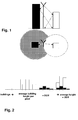
- Fig. 1 illustrates a ray launching scenario.
- a bundle of rays emanates from a transmitter source.
- a 3D model of the environment is accessed to determine the nearest obstacle in the current propagation direction of the ray.
- the rays are traced over a few reflections or until their field strength falls below a defined threshold value.
- the ray launching algorithm includes the radio wave propagation effects reflection, diffraction, and diffuse scattering including de-polarization in its ongoing calculation of k, d k , and a k (see (2)) based on the algorithms of Geometrical Optics, the Uniform Theory of Diffraction, and, possibly, the Effective Roughness approach.
- channel impulse response can be extended to a multi-antenna channel impulse response matrices can be derived incorporating the underlying propagation effects of these antenna types.
- ULA type antennas consist of multiple equal antenna elements at a uniform distance along a linear array.
- ⁇ d k + ( m -1) ⁇ cos( ⁇ ), where: m is the antenna element number with M r being the number of receiver antenna elements and M t being the number of transmitter antenna elements, ⁇ is the inter-element antenna spacing normalized to ⁇ , and ⁇ is the angle of the outgoing or incoming plane wave to the direction of the array.
- the superscript * denotes the Hermitian transpose of a complex matrix.
- each matrix elements reflects the channel impulse response calculated by (2) but for different combinations of the polarization of the transmitting and receiving antenna elements.
- this MIMO channel impulse response is directly obtained as a result.
- RRH types of antennas in this disclosure are intended to be single-element antennas positioned at different locations, e.g. at two corners of a roof.
- the above described plane-wave model can again be used for the receiving antenna elements. Since we assume the RRH antenna elements at complete different positions thus expecting two de-correlated channel impulse responses, we need to calculate a channel impulse response using (1) for every single RRH antenna element.
- the lower limit of the Gain MIMO is the value of one: There is no capacity advantage of the MIMO channel compared to the SISO channel. Without beam forming, the upper limit of Gain MIMO is the maximum rank of the channel impulse response matrix (min (M r , M t )) in case of spatial multiplexing, and M r in case of diversity at low SINR values.
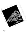
- Fig. 2 shows the definition of a clutter height matrix which can advantageously be used as a 3D model of the environment of a planning/optimizing area. Building heights are retracted from a 3D topological database, and an average height per unity area is calculated with a fixed resolution. This will be sufficient for flat areas. In a hilly or mountainous environment however, it would be desirable to correct the building height matrix by a Digital Elevation Matrix (DEM) which represents geological heights of the area. A resulting 3D clutter height matrix from is shown in Fig. 3 .
- DEM Digital Elevation Matrix
- a second embodiment of the invention proposes to limit the ray launching algorithm to a few reflections, at most three, and to look for dominant paths through the environment represented by a clutter height matrix as shown in Fig. 3 .
- Figs. 4 through 8 show examples of a spatial resolution of different multi-antenna types into effective activity sectors for each single antenna element of the respective multi-antenna type.
- An antenna array here, is to be understood as an arrangement of single antenna elements disposed in a plane or optionally in two perpendicular planes in a 3DCartesian coordinate system.
- a single antenna element is defined by any internal construction and by a single external connection to a signal input/output, respectively.
- the number of orthogonal units is defined by the number of individual elements N of the antenna array in the respective plane.
- ⁇ is the inter-element antenna spacing normalized to the wavelength ⁇ of the carrier frequency.
- ⁇ is the inter-element antenna spacing normalized to the wavelength ⁇ of the carrier frequency.
- Figs. 4a,b show a directional diagram of a ULA consisting of 2 single antenna elements, each one being a Hertzian dipole, with a spacing of ⁇ /2, and the spatial bins derived therefrom;
- Figs. 5 a,b show a directional diagram of a ULA consisting of 4 single antenna elements, each one being a Hertzian dipole, with a spacing of ⁇ /2, and spatial bins derived therefrom;
- Figs. 6a,b show a directional diagram of a sector antenna with a 3dB angle of 65°, and a spatial bin derived therefrom;
- Figs. 4a,b show a directional diagram of a ULA consisting of 2 single antenna elements, each one being a Hertzian dipole, with a spacing of ⁇ /2, and the spatial bins derived therefrom;
- Figs. 5 a,b show a directional diagram of a ULA consisting of 4 single antenna elements, each one being
- FIG. 7a,b show a directional diagram of a ULA consisting of 2 single antenna elements, each one being a sector antenna with a 3dB angle of 65°, with a spacing of ⁇ /2, and spatial bins derived therefrom; and Figs. 8a,b show a directional diagram of a ULA consisting of 4 single antenna elements, each one being a sector antenna with a 3dB angle of 65°, with a spacing of ⁇ /2, and spatial bins derived therefrom.
- a multi-antenna type comprising a plurality of single antenna elements which are spaced by a larger distance than a few multiples of the wavelength of the transmit or receive carrier frequency (i.e. RRH) and which are operated as a multi-antenna
- a multi-antenna comprising a plurality of single antenna elements which are individual antennas and which are operated in different sectors of a base station, in different base stations at different positions in the 3D environment, and/or in a combination thereof and which are operated as a multi-antenna in the sense of a Cooperative Multipoint (CoMP) (sector and/or network-MIMO)
- spatial bins are defined by an acute, and optionally tilted pyramid, the peak of which is arranged at the 3D center of the multi-antenna and the side faces of which are limited in a specified distance from the 3D center position of the multi-antenna as follows: In the horizontal direction by a fading amount defined in the horizontal antenna diagram R( ⁇ )
- a multi-antenna type comprising a plurality of single antenna elements which are spaced by different polarization directions (e.g. XPoI) spatial bins are defined by an acute, and optionally tilted pyramid, the peak of which is arranged at the 3D center of the multi-antenna and the side faces of which are limited in a specified distance from the 3D center position of the multi-antenna as follows: in the horizontal direction by a fading amount defined in the horizontal antenna diagram R( ⁇ ) relative to the main beam direction of the transmit multi-antenna in horizontal direction; and in the vertical direction, by a fading amount defined in the vertical antenna diagram R( ⁇ ) relative to the main beam direction of the transmit multi-antenna upwards, and by a fading amount defined in the vertical antenna diagram relative to the main beam direction of the transmit multi-antenna downwards.
- XPoI polarization directions
- the spatial bin pyramids can be internally divided into ray tubes the size of which is equally set in horizontal and vertical direction:
- the ray launching/tracing algorithm includes launching a respective ray through each tube into the 3D model of the environment.
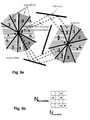
- Fig. 9a schematically shows an example of paths found by performimng a limited ray tracing algorithm which is limited to finding paths comprising only a small number of reflections (only one reflection in the figure) between the individual spatial bins of two multi-antennas of a type illustrated in Figs. 5a and b
- Fig. 9b shows a matrix population derived from Fig. 9a .
- 'populated' An orthogonal unit from which a configurable minimum number of paths emanate into or arrive from an environment is referred to as 'populated'.
- the presence and the multiplicity of the advantage 'spatial multiplexing' in multi-antenna systems and 'diversity' can now simply be determined from the population state of the spatial bins of the transmit and receive antenna arrays.
- the spatial bins of the transmit and receive antenna arrays are arranged in form of a matrix wherein the spatial bins of the transmit antenna array form the columns of the matrix, and the spatial bins of the receive antenna array form the rows of the matrix.
- the matrix is populated with paths found between any of the one spatial bins representing the individual antenna elements of transmit and receive antenna arrays.
- Fig. 9a five dominant paths have been found, from transmitter spatial bin 4 to receiver spatial bins 3 and 4, from transmitter spatial bin 2 to receiver spatial bins 3 and 1, and from transmitter spatial bin 1 to receiver spatial bin 3, as illustrated in the matrix of Fig. 9b .
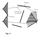
- Fig. 10 schematically shows an example of ray tracing limited to path finding between two multi-antennas of a type illustrated in Figs. 7 and 8 (i.e. transmit antenna: 4xULA with single elements as sector antenna; receive antenna: 2xULA with single elements as sector antenna)
- Similar matrices as illustrated in Fig. 9b can be derived for the scenarios of Figs. 10 and 11 .
- the scalar metric Gain MIMO has assigned a first value if at least one row or column in said propagation path matrix is populated by at least two elements, indicating a degree of spatial diversity, and said scalar metric has assigned a second value if at least two rows and at least two columns in said propagation path matrix are populated by at least two elements, indicating a degree of spatial multiplexing.
- the scalar metric Gain MIMO has assigned a third value if there is a line-of-sight relationship between a spatial bin of the transmit multi-antenna and a spatial bin of the receive multi-antenna, and has assigned a fourth value if there is no line-of-sight relationship between a spatial bin of the transmit multi-antenna and a spatial bin of the receive multi-antenna.
- the first, second, third, and/or fourth values can be weighted, if desired, to reflect preference of a specific antenna type in terms of any economic feature defined by the network operator and the like.
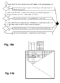
- Figs. 12 to 14 show three exemplary embodiments of the step of determining, for each receiver pixel within a coverage sector of the planning/optimizing area, an optimum multi-antenna type.
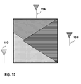
- the coverage sectors of a planning/optimizing area are usually derived from a scheme as shown in Fig. 15 and known as "best server plot".
- Such a best server plot can be obtained by a network operator and illustrates which section of a deployment area is best served in terms of the physical metric 'coverage' by which base station antenna position 15A, B, C.
- Figs, 12a , 13a , and 14a each show a flow chart of a decision step for selecting the better antenna type out of two different multi-antenna types using the propagation path matrix described above.
- Figs, 12b , 13b , and 14b each show a respective simplified schematic plot which is derived as a result of the evaluation procedure of Figs, 12a , 13a , and 14a , respectively.
- the planning/optimizing area is divided into three coverage sectors as shown in Fig. 15 .
- a decision for a best multi-antenna type per receiver pixel is illustrated for only one coverage sector, the receiver pixels in which the respective antenna type performs best being marked with the same pattern as the corresponding antenna type.
- Figs. 12a, b illustrate a decision made between an ULA comprising two single antenna elements and a ULA comprising four single antenna elements, in brief: 2-ULA vs. 4-ULA. If at least one antenna type exhibits the advantage "multiplexing", i.e. the scalar metric Gain MIMO has assigned the second value, the antenna type with the highest spatial multiplexing degree is selected as the optimum multi-antenna type for this receiver pixel. If no antenna type exhibits the advantage "multiplexing" but at least one antenna type exhibits the advantage "diversity", i.e.
- the scalar metric Gain MIMO has assigned the first value, the antenna type with the highest spatial diversity degree is selected as the optimum multi-antenna type for this receiver pixel. If no antenna type exhibits the advantage "multiplexing" or "diversity", a deployment of a multi-antenna type will not result in any advantage from spatial diversity or multiplexing.
- Figs. 13a, b illustrate a decision made between a ULA type and a cross-polarized antenna type, in brief: ULA vs. XPoI. If the scalar metric Gain MIMO for the ULA type has assigned the second value, indicating a spatial multiplexing degree of more than 2, the spatial antenna type with the highest spatial multiplexing degree is selected as the optimum multi-antenna type for this receiver pixel.
- the XPoI type is selected as the optimum multi-antenna type for this receiver pixel.
- the spatial antenna type is selected as the optimum multi-antenna type for this receiver pixel. If non of the above conditions is true, the XPoI type is selected as the optimum multi-antenna type for this receiver pixel.
- Figs. 14a, b illustrate a decision made between a ULA type and a combination of ULA and cross-polarized antenna comprising two cross-polarized antennas that are arranged in a linear array, in brief: ULA vs. 2-(ULA+XpoI). If the scalar metric Gain MIMO for the ULA type has assigned the second value, indicating a spatial multiplexing degree of more than 4, the spatial antenna type with the highest spatial multiplexing degree is selected as the optimum multi-antenna type for this receiver pixel.
- the scalar metric Gain MIMO for the ULA type has assigned the second value, indicating a spatial multiplexing degree of 2 or more
- the scalar metric Gain MIMO for the XPoI combination type has assigned the third value indicating a line-of-sight (LOS) relationship
- the XPoI combination type is selected as the optimum multi-antenna type for this receiver pixel.
- both antenna types produce the same advantage and both antenna types are equally weighted in subsequent evaluation of a best antenna type per sector. If non of the above conditions is true, the XPoI combination type is selected as the optimum multi-antenna type for this receiver pixel.
- Such a plot is easily assessed in view of what antenna type is best suited as a multi-antenna type at a specific base station site to serve the entire coverage sector.
- a first possibility is to simply count the receiver pixels preferring a respective antenna type and to select the multi-antenna type which is determined the best multi-antenna type at the majority of receiver grid points of a coverage sector as the optimum multi-antenna type for the best covering transmitter position of each coverage sector.
- the receiver pixels can be weighted, e.g. with a value representing a predicted traffic density and/or traffic volume, and the multi-antenna type for which the weighted sum of the scalar metrics of the receiver grid points is highest can be selected as the optimum multi-antenna type for the best covering transmitter position of each coverage sector.
- An exemplary simulation was performed in a cellular network in a dense urban European city.
- the network has a size of about 2 sq. mi (3.5 km 2 ) and consists of three sites with three sectors each.
- the sector antennas point towards 60 deg, 180 deg, and 300 deg and are located well above (about 50 m) the average building heights (about 15 m).
- the radio wave propagation was simulated by the ray launching channel simulator as described above. Receiver positions were placed in a 10 m x 10 m grid (Option 1). In a variation, we placed our receivers in a 10 m distance around buildings only (Option 2) in order to check indoor MIMO performance.
- This rough model assumes windows at all buildings in a 10 m grid. Since penetration is not modeled in the ray launching tool we can especially investigate the MIMO performance of a situation where radio waves only arrive at the receiver from the side of the building where the window is situated.
- the receivers are served by four of a total of nine sectors.
- the model used as single antenna element for all discussed antenna types was a typical commercial antenna with a 3dB beam width of 65 deg, an electrical down tilt of 6 deg and a gain of 16.57 dBi.
- the artificial model of an isotropic source with 0 dBi gain was used as model for a single antenna element.
- the result of the ray launching simulations is a channel impulse response as represented in (2) for every receiver position.
- the ray launching tool also outputs the angles of all outgoing (transmitting side) and incoming (receiving side) rays which are needed for the calculation of (3). Since our ray launching simulator is fully polarimetric, the XPoI channel matrix as represented in (4) is also a direct channel simulation result.
- the results of this analysis are presented in the table below.
- the table shows four main columns, each one for one of the four sectors serving the receivers. The selection as to which sector serves which receiver was made based on a best server plot as schematically illustrated in Fig. 14 . Further, the table shows for both configurations the percentage [%] of the total number of receiver pixels that are served by a respective sector, and the percentage [%] of the total number of receiver pixels that have a higher metric Gain MIMO for one of the two investigated multi-antenna types.
- sector 2 has an overall coverage of 42.0 % of the complete area.
- sector 2 has an XPoI antenna, then 58.1 % out of its coverage area have a higher Gain MIMO compared with 41.9 % of receivers that would have a higher Gain MIMO in case this sector would have an ULA antenna.
- sector 2 should be deployed with an XPoI antenna. This is also true for sectors 3 and 4, but not for sector 1.
Landscapes
- Engineering & Computer Science (AREA)
- Computer Networks & Wireless Communication (AREA)
- Signal Processing (AREA)
- Physics & Mathematics (AREA)
- Electromagnetism (AREA)
- Mobile Radio Communication Systems (AREA)
- Radio Transmission System (AREA)
Priority Applications (2)
| Application Number | Priority Date | Filing Date | Title |
|---|---|---|---|
| EP20100156606 EP2230863A3 (de) | 2009-03-16 | 2010-03-16 | Verfahren zur Annäherung und Optimierung von Kapazitäts- und Abdeckungsverstärkung infolge der Verwendung von Multiantennen in zellularen Funknetzwerken |
| CN2010101582745A CN102195690A (zh) | 2010-03-16 | 2010-03-31 | 估算/优化蜂窝无线网络中多天线配置产生的容量增益以及覆盖范围的方法 |
Applications Claiming Priority (2)
| Application Number | Priority Date | Filing Date | Title |
|---|---|---|---|
| EP09155250 | 2009-03-16 | ||
| EP20100156606 EP2230863A3 (de) | 2009-03-16 | 2010-03-16 | Verfahren zur Annäherung und Optimierung von Kapazitäts- und Abdeckungsverstärkung infolge der Verwendung von Multiantennen in zellularen Funknetzwerken |
Publications (2)
| Publication Number | Publication Date |
|---|---|
| EP2230863A2 true EP2230863A2 (de) | 2010-09-22 |
| EP2230863A3 EP2230863A3 (de) | 2015-04-22 |
Family
ID=42116005
Family Applications (1)
| Application Number | Title | Priority Date | Filing Date |
|---|---|---|---|
| EP20100156606 Withdrawn EP2230863A3 (de) | 2009-03-16 | 2010-03-16 | Verfahren zur Annäherung und Optimierung von Kapazitäts- und Abdeckungsverstärkung infolge der Verwendung von Multiantennen in zellularen Funknetzwerken |
Country Status (3)
| Country | Link |
|---|---|
| US (1) | US8428171B2 (de) |
| EP (1) | EP2230863A3 (de) |
| JP (1) | JP5139462B2 (de) |
Cited By (4)
| Publication number | Priority date | Publication date | Assignee | Title |
|---|---|---|---|---|
| WO2014021962A3 (en) * | 2012-05-18 | 2014-04-03 | Raytheon Company | Method and system for predicting energy on target |
| WO2014140495A1 (fr) * | 2013-03-13 | 2014-09-18 | Softwave Wireless | Procédé de prédiction du niveau de champ radio et/ou de la durée de propagation des réseaux de téléphonie cellulaire utilisant des bases de données terrain à haute résolution |
| WO2014158923A1 (en) * | 2013-03-14 | 2014-10-02 | Microsoft Corporation | Dynamic wireless configuration for video conference environments |
| US9100122B2 (en) | 2012-05-18 | 2015-08-04 | Raytheon Company | Method and system to analyze interference susceptibility of a radio receiver design |
Families Citing this family (22)
| Publication number | Priority date | Publication date | Assignee | Title |
|---|---|---|---|---|
| FR2968865A1 (fr) * | 2010-12-08 | 2012-06-15 | Thomson Licensing | Dispositif de reception ou d'emission/reception de signaux mimo |
| JP2013197719A (ja) * | 2012-03-16 | 2013-09-30 | Nec Corp | 無線通信装置、無線通信システム、無線通信方法 |
| JP2015073260A (ja) | 2013-09-04 | 2015-04-16 | 富士通株式会社 | 無線通信システム、及び、無線通信方法 |
| CN104283597B (zh) * | 2013-11-25 | 2018-03-27 | 北京邮电大学 | 一种波束赋形方法及设备 |
| WO2015084350A1 (en) * | 2013-12-04 | 2015-06-11 | Hitachi, Ltd. | A method for ue-assisted antenna parameters optimization |
| JP6172390B2 (ja) * | 2014-05-29 | 2017-08-02 | トヨタ自動車株式会社 | アレーアンテナ装置 |
| CN107333278A (zh) * | 2017-06-30 | 2017-11-07 | 北京世纪德辰通信技术有限公司 | 一种公众移动通信信号覆盖可视化实现方法 |
| CN109412723B (zh) * | 2017-08-16 | 2020-06-16 | 中兴通讯股份有限公司 | 一种mimo信道分析模型、建模方法及计算机可读存储介质 |
| KR102442490B1 (ko) | 2017-09-27 | 2022-09-13 | 삼성전자 주식회사 | 무선 통신 시스템에서 분산 처리에 기반한 망 설계를 위한 분석 방법 및 장치 |
| KR102584996B1 (ko) | 2018-07-05 | 2023-10-05 | 삼성전자주식회사 | 무선 네트워크 디자인 방법, 저장매체 및 전자 장치 |
| CN110545131B (zh) * | 2019-08-07 | 2020-08-04 | 湖南国科锐承电子科技有限公司 | 毫米波视距mimo信道下的天线阵列设计方法和系统 |
| US10973062B2 (en) * | 2019-08-26 | 2021-04-06 | International Business Machines Corporation | Method for extracting environment information leveraging directional communication |
| US11622287B2 (en) * | 2020-06-23 | 2023-04-04 | Verizon Patent And Licensing Inc. | Upgrade recommendations for wireless wide area networks |
| US11277166B2 (en) * | 2020-06-26 | 2022-03-15 | Robert Bosch Gmbh | Occupancy sensing using ultra-wide band |
| CN114697973B (zh) * | 2020-12-25 | 2023-08-04 | 大唐移动通信设备有限公司 | 小区天线类型的确定方法、装置及存储介质 |
| JP7593480B2 (ja) | 2021-04-05 | 2024-12-03 | 日本電信電話株式会社 | 情報処理システム、レイトレース方法、及びプログラム |
| WO2022215138A1 (ja) * | 2021-04-05 | 2022-10-13 | 日本電信電話株式会社 | 情報処理システム、電波伝搬シミュレーション方法、及びプログラム |
| CN113095519B (zh) * | 2021-04-09 | 2023-11-10 | 北京东方博泰正通通信工程有限责任公司 | 一种一体化基站天线 |
| CN116347461A (zh) * | 2021-12-24 | 2023-06-27 | 亿阳信通股份有限公司 | 一种5g网络中天线的调整方法及装置 |
| US12520177B2 (en) * | 2022-12-14 | 2026-01-06 | Rakuten Symphony, Inc. | Geography based-KPI analysis of a wireless network |
| US20250306164A1 (en) * | 2024-03-14 | 2025-10-02 | Mitsubishi Electric Research Laboratories, Inc. | System and Method for DMG Passive Sensing in an Environment |
| CN120357985B (zh) * | 2025-06-26 | 2025-09-30 | 南京捷希科技股份有限公司 | 一种面向超大规模mimo通信的射线追踪信道建模方法 |
Citations (1)
| Publication number | Priority date | Publication date | Assignee | Title |
|---|---|---|---|---|
| WO2005069666A1 (de) | 2004-01-15 | 2005-07-28 | Radioplan Gmbh | Verfahren und vorrichtung zur anpassung eines funknetzmodells an die bedingungen eines realen funknetzes |
Family Cites Families (19)
| Publication number | Priority date | Publication date | Assignee | Title |
|---|---|---|---|---|
| FI107366B (fi) * | 1998-10-29 | 2001-07-13 | Nokia Networks Oy | Menetelmä ja laitteisto verkkosuunnittelun toteuttamiseksi |
| US6317599B1 (en) * | 1999-05-26 | 2001-11-13 | Wireless Valley Communications, Inc. | Method and system for automated optimization of antenna positioning in 3-D |
| US6842431B2 (en) * | 1999-11-04 | 2005-01-11 | Lucent Technologies Inc. | Methods and apparatus for characterization, adjustment and optimization of wireless networks |
| US6662024B2 (en) * | 2001-05-16 | 2003-12-09 | Qualcomm Incorporated | Method and apparatus for allocating downlink resources in a multiple-input multiple-output (MIMO) communication system |
| JP2003318811A (ja) * | 2002-04-26 | 2003-11-07 | Nippon Telegr & Teleph Corp <Ntt> | 受信電界強度推定計算装置及び方法並びにプログラム及び記録媒体 |
| KR100900970B1 (ko) * | 2002-10-19 | 2009-06-08 | 삼성전자주식회사 | 기지국/이동국 다중안테나를 포함하는 이동통신장치 및 방법 |
| JP4819303B2 (ja) * | 2002-10-23 | 2011-11-24 | 日本電気株式会社 | 移動通信システムにおける基地局設置設計方法及び基地局設置設計装置並びにプログラム |
| AU2003296072A1 (en) * | 2002-12-24 | 2004-07-22 | Matsushita Electric Industrial Co., Ltd. | Transmission path simulation method and transmission path simulator |
| US20040259554A1 (en) * | 2003-04-23 | 2004-12-23 | Rappaport Theodore S. | System and method for ray tracing using reception surfaces |
| EP1639732A2 (de) * | 2003-06-30 | 2006-03-29 | Nokia Corporation | Vorrichtung und assoziiertes verfahren zum prüfen eines mobilen endgeräts in testbedingungen, die eine betriebsumgebung emulieren |
| US7212160B2 (en) * | 2004-02-17 | 2007-05-01 | Polytechnic University | Locating an object of interest using back tracked-rays derived from multipath signals |
| US8019352B2 (en) * | 2004-07-23 | 2011-09-13 | Wireless Valley Communications, Inc. | System, method, and apparatus for determining and using the position of wireless devices or infrastructure for wireless network enhancements |
| JP2006170698A (ja) * | 2004-12-14 | 2006-06-29 | Matsushita Electric Ind Co Ltd | 無線局方向推定装置及び無線局方向推定・電波発射装置、並びに無線局方向推定方法 |
| JP2007078482A (ja) * | 2005-09-13 | 2007-03-29 | Matsushita Electric Ind Co Ltd | アダプティブアレーアンテナの特性評価方法及び装置 |
| US7715844B2 (en) * | 2006-03-21 | 2010-05-11 | Alcatel-Lucent Usa Inc. | Spatial channel model with a three-dimensional cloud of scatterers |
| US8670777B2 (en) * | 2006-09-08 | 2014-03-11 | Qualcomm Incorporated | Method and apparatus for fast other sector interference (OSI) adjustment |
| JP2008124974A (ja) * | 2006-11-15 | 2008-05-29 | Nec Corp | 無線通信システム及び無線通信装置 |
| US7962102B2 (en) * | 2006-11-30 | 2011-06-14 | Motorola Mobility, Inc. | Method and system for adaptive ray launching |
| US9031613B2 (en) * | 2007-12-21 | 2015-05-12 | University Of New Brunswick | Joint communication and electromagnetic optimization of a multiple-input multiple-output ultra wideband base station antenna |
-
2010
- 2010-03-16 US US12/724,746 patent/US8428171B2/en not_active Expired - Fee Related
- 2010-03-16 JP JP2010059342A patent/JP5139462B2/ja not_active Expired - Fee Related
- 2010-03-16 EP EP20100156606 patent/EP2230863A3/de not_active Withdrawn
Patent Citations (1)
| Publication number | Priority date | Publication date | Assignee | Title |
|---|---|---|---|---|
| WO2005069666A1 (de) | 2004-01-15 | 2005-07-28 | Radioplan Gmbh | Verfahren und vorrichtung zur anpassung eines funknetzmodells an die bedingungen eines realen funknetzes |
Non-Patent Citations (5)
| Title |
|---|
| A. M. SAYEED: "Deconstructing Multi-Antenna Fading Channels", IEEE TRANSACTIONS ON SIGNAL PROCESSING, vol. 50, no. 10, 20 February 1000 (1000-02-20), pages 2563 - 2579 |
| CLAUDE ELWOOD SHANNON: "A Mathematical Theory of Communication", BELL SYSTEM TECHNICAL JOURNAL, vol. 27, 7031219, pages 379 - 423,623-656 |
| G. J. FOSCHINI; M. J. GANS: "On Limits of Wireless Communications in a Fading Environment When Using Multiple Antennas", WIRELESS PERSONAL COMMUNICATIONS, vol. 6, no. 3, 3080219, pages 311 - 335 |
| J. P. KERMOAL; L. SCHUMACHER; F. FREDERIKSEN; P. E. MOGENSEN: "Polarization Diversity in MIMO Radio Channels: Experimental Validation of a Stochastic Model and Performance Assessment", IEEE VTC FALL, 20 January 1000 (1000-01-20) |
| V. R. ANREDDY; M. A. INGRAM: "Capacity of Measured Ricean and Rayleigh Indoor MIMO Channels at 2.5 GHz with Polarization and Spatial Diversity", IEEE WCNC, 4000620 |
Cited By (11)
| Publication number | Priority date | Publication date | Assignee | Title |
|---|---|---|---|---|
| WO2014021962A3 (en) * | 2012-05-18 | 2014-04-03 | Raytheon Company | Method and system for predicting energy on target |
| US8957811B2 (en) | 2012-05-18 | 2015-02-17 | Raytheon Company | Method and system for predicting energy on target |
| GB2518997A (en) * | 2012-05-18 | 2015-04-08 | Raytheon Co | Method and system for predicting energy on target |
| US9100122B2 (en) | 2012-05-18 | 2015-08-04 | Raytheon Company | Method and system to analyze interference susceptibility of a radio receiver design |
| AU2013297107B2 (en) * | 2012-05-18 | 2015-08-06 | Raytheon Company | Method and system for predicting energy on target |
| GB2518997B (en) * | 2012-05-18 | 2019-12-25 | Raytheon Co | Method and system for predicting energy on target |
| WO2014140495A1 (fr) * | 2013-03-13 | 2014-09-18 | Softwave Wireless | Procédé de prédiction du niveau de champ radio et/ou de la durée de propagation des réseaux de téléphonie cellulaire utilisant des bases de données terrain à haute résolution |
| FR3003425A1 (fr) * | 2013-03-13 | 2014-09-19 | Softwave Wireless | Procede de prediction du niveau de champ radio des reseaux de telephonie cellulaire utilisant des bases de donnees terrain a haute resolution |
| US9635562B2 (en) | 2013-03-13 | 2017-04-25 | Google Inc. | Method for predicting the radio field level and/or the duration of propagation of cellular telephone networks using high-resolution terrain databases |
| WO2014158923A1 (en) * | 2013-03-14 | 2014-10-02 | Microsoft Corporation | Dynamic wireless configuration for video conference environments |
| US8988485B2 (en) | 2013-03-14 | 2015-03-24 | Microsoft Technology Licensing, Llc | Dynamic wireless configuration for video conference environments |
Also Published As
| Publication number | Publication date |
|---|---|
| JP2010226713A (ja) | 2010-10-07 |
| EP2230863A3 (de) | 2015-04-22 |
| US20100232529A1 (en) | 2010-09-16 |
| US8428171B2 (en) | 2013-04-23 |
| JP5139462B2 (ja) | 2013-02-06 |
Similar Documents
| Publication | Publication Date | Title |
|---|---|---|
| US8428171B2 (en) | Method for approximating and optimizing gains in capacity and coverage resulting from deployment of multi-antennas in cellular radio networks | |
| Samimi et al. | 28 GHz millimeter-wave ultrawideband small-scale fading models in wireless channels | |
| Oestges et al. | Propagation modeling of MIMO multipolarized fixed wireless channels | |
| Fuschini et al. | Ray tracing propagation modeling for future small-cell and indoor applications: A review of current techniques | |
| Raghavan et al. | Millimeter wave channel measurements and implications for PHY layer design | |
| Jiang et al. | Spherical-wave model for short-range MIMO | |
| US11962097B2 (en) | Method and apparatus for selecting antenna elements of an antenna array | |
| CN102195690A (zh) | 估算/优化蜂窝无线网络中多天线配置产生的容量增益以及覆盖范围的方法 | |
| Abouda et al. | Effect of antenna array geometry and ULA azimuthal orientation on MIMO channel properties in urban city street grid | |
| Jiang et al. | Distributed source model for short-range MIMO | |
| Forooshani et al. | Effect of antenna configuration on MIMO-based access points in a short tunnel with infrastructure | |
| Lee et al. | Indoor space-time propagation modelling using a ray launching technique | |
| Arikawa et al. | A simplified MIMO channel characteristics evaluation scheme based on ray tracing and its application to indoor radio systems | |
| Kaya et al. | Modeling three dimensional channel characteristics in outdoor-to-indoor LTE small cell environments | |
| Aslam et al. | Massive MIMO channel performance analysis considering separation of simultaneous users | |
| Voigt et al. | Optimal antenna type selection in a real SU-MIMO network planning scenario | |
| Ng et al. | Modelling and performance prediction for multiple antenna systems using enhanced ray tracing | |
| Ling et al. | Peer-to-peer MIMO radio channel measurements in a rural area | |
| Haneda et al. | Development of multi-link geometry-based stochastic channel models | |
| Solomitckii et al. | Detailed interference analysis in dense mmwave systems employing dual-polarized antennas | |
| Hasan et al. | The impact of linear polarization on channel modeling in 5G cellular communications: A Statistical approach | |
| Fritzsche et al. | Verifying ray tracing based CoMP-MIMO predictions with channel sounding measurements | |
| Strelnikov et al. | Environment-Specific Ray-Tracing Channel Modeling in Massive MIMO Systems | |
| Bshara et al. | Computational electromagnetic simulation and performance analysis of reconfigurable antennas for outdoor 60 GHz applications | |
| Yang et al. | Spatial dispersion and performance evaluation of indoor MIMO channels at 2.25 GHz |
Legal Events
| Date | Code | Title | Description |
|---|---|---|---|
| PUAI | Public reference made under article 153(3) epc to a published international application that has entered the european phase |
Free format text: ORIGINAL CODE: 0009012 |
|
| AK | Designated contracting states |
Kind code of ref document: A2 Designated state(s): AT BE BG CH CY CZ DE DK EE ES FI FR GB GR HR HU IE IS IT LI LT LU LV MC MK MT NL NO PL PT RO SE SI SK SM TR |
|
| AX | Request for extension of the european patent |
Extension state: AL BA ME RS |
|
| PUAL | Search report despatched |
Free format text: ORIGINAL CODE: 0009013 |
|
| AK | Designated contracting states |
Kind code of ref document: A3 Designated state(s): AT BE BG CH CY CZ DE DK EE ES FI FR GB GR HR HU IE IS IT LI LT LU LV MC MK MT NL NO PL PT RO SE SI SK SM TR |
|
| AX | Request for extension of the european patent |
Extension state: AL BA ME RS |
|
| RIC1 | Information provided on ipc code assigned before grant |
Ipc: H01Q 1/24 20060101ALI20150316BHEP Ipc: H01Q 25/00 20060101AFI20150316BHEP |
|
| 17P | Request for examination filed |
Effective date: 20151022 |
|
| RBV | Designated contracting states (corrected) |
Designated state(s): AT BE BG CH CY CZ DE DK EE ES FI FR GB GR HR HU IE IS IT LI LT LU LV MC MK MT NL NO PL PT RO SE SI SK SM TR |
|
| STAA | Information on the status of an ep patent application or granted ep patent |
Free format text: STATUS: THE APPLICATION IS DEEMED TO BE WITHDRAWN |
|
| 18D | Application deemed to be withdrawn |
Effective date: 20171003 |