EP3314174B1 - Chaudière à condensation comportant un échangeur de chaleur enroulé avec une tuyauterie disposée en spirale - Google Patents
Chaudière à condensation comportant un échangeur de chaleur enroulé avec une tuyauterie disposée en spirale Download PDFInfo
- Publication number
- EP3314174B1 EP3314174B1 EP16770372.7A EP16770372A EP3314174B1 EP 3314174 B1 EP3314174 B1 EP 3314174B1 EP 16770372 A EP16770372 A EP 16770372A EP 3314174 B1 EP3314174 B1 EP 3314174B1
- Authority
- EP
- European Patent Office
- Prior art keywords
- condensation
- profile
- heat exchanger
- boiler
- base
- Prior art date
- Legal status (The legal status is an assumption and is not a legal conclusion. Google has not performed a legal analysis and makes no representation as to the accuracy of the status listed.)
- Active
Links
- 238000009833 condensation Methods 0.000 title claims description 64
- 230000005494 condensation Effects 0.000 title claims description 64
- 238000002485 combustion reaction Methods 0.000 claims description 23
- 239000003517 fume Substances 0.000 description 16
- 239000012530 fluid Substances 0.000 description 5
- 239000007788 liquid Substances 0.000 description 5
- 239000007789 gas Substances 0.000 description 2
- 238000010438 heat treatment Methods 0.000 description 2
- 230000005855 radiation Effects 0.000 description 2
- 238000000926 separation method Methods 0.000 description 2
- WYTGDNHDOZPMIW-RCBQFDQVSA-N alstonine Natural products C1=CC2=C3C=CC=CC3=NC2=C2N1C[C@H]1[C@H](C)OC=C(C(=O)OC)[C@H]1C2 WYTGDNHDOZPMIW-RCBQFDQVSA-N 0.000 description 1
- 230000001174 ascending effect Effects 0.000 description 1
- 239000000567 combustion gas Substances 0.000 description 1
- 230000001419 dependent effect Effects 0.000 description 1
- 239000011810 insulating material Substances 0.000 description 1
- 230000004048 modification Effects 0.000 description 1
- 238000012986 modification Methods 0.000 description 1
- 239000011819 refractory material Substances 0.000 description 1
Images


Classifications
-
- F—MECHANICAL ENGINEERING; LIGHTING; HEATING; WEAPONS; BLASTING
- F24—HEATING; RANGES; VENTILATING
- F24H—FLUID HEATERS, e.g. WATER OR AIR HEATERS, HAVING HEAT-GENERATING MEANS, e.g. HEAT PUMPS, IN GENERAL
- F24H1/00—Water heaters, e.g. boilers, continuous-flow heaters or water-storage heaters
- F24H1/22—Water heaters other than continuous-flow or water-storage heaters, e.g. water heaters for central heating
- F24H1/40—Water heaters other than continuous-flow or water-storage heaters, e.g. water heaters for central heating with water tube or tubes
- F24H1/43—Water heaters other than continuous-flow or water-storage heaters, e.g. water heaters for central heating with water tube or tubes helically or spirally coiled
-
- F—MECHANICAL ENGINEERING; LIGHTING; HEATING; WEAPONS; BLASTING
- F24—HEATING; RANGES; VENTILATING
- F24H—FLUID HEATERS, e.g. WATER OR AIR HEATERS, HAVING HEAT-GENERATING MEANS, e.g. HEAT PUMPS, IN GENERAL
- F24H1/00—Water heaters, e.g. boilers, continuous-flow heaters or water-storage heaters
- F24H1/10—Continuous-flow heaters, i.e. heaters in which heat is generated only while the water is flowing, e.g. with direct contact of the water with the heating medium
- F24H1/12—Continuous-flow heaters, i.e. heaters in which heat is generated only while the water is flowing, e.g. with direct contact of the water with the heating medium in which the water is kept separate from the heating medium
- F24H1/14—Continuous-flow heaters, i.e. heaters in which heat is generated only while the water is flowing, e.g. with direct contact of the water with the heating medium in which the water is kept separate from the heating medium by tubes, e.g. bent in serpentine form
- F24H1/16—Continuous-flow heaters, i.e. heaters in which heat is generated only while the water is flowing, e.g. with direct contact of the water with the heating medium in which the water is kept separate from the heating medium by tubes, e.g. bent in serpentine form helically or spirally coiled
-
- F—MECHANICAL ENGINEERING; LIGHTING; HEATING; WEAPONS; BLASTING
- F24—HEATING; RANGES; VENTILATING
- F24H—FLUID HEATERS, e.g. WATER OR AIR HEATERS, HAVING HEAT-GENERATING MEANS, e.g. HEAT PUMPS, IN GENERAL
- F24H1/00—Water heaters, e.g. boilers, continuous-flow heaters or water-storage heaters
- F24H1/22—Water heaters other than continuous-flow or water-storage heaters, e.g. water heaters for central heating
- F24H1/44—Water heaters other than continuous-flow or water-storage heaters, e.g. water heaters for central heating with combinations of two or more of the types covered by groups F24H1/24 - F24H1/40 , e.g. boilers having a combination of features covered by F24H1/24 - F24H1/40
- F24H1/445—Water heaters other than continuous-flow or water-storage heaters, e.g. water heaters for central heating with combinations of two or more of the types covered by groups F24H1/24 - F24H1/40 , e.g. boilers having a combination of features covered by F24H1/24 - F24H1/40 with integrated flue gas condenser
-
- F—MECHANICAL ENGINEERING; LIGHTING; HEATING; WEAPONS; BLASTING
- F24—HEATING; RANGES; VENTILATING
- F24H—FLUID HEATERS, e.g. WATER OR AIR HEATERS, HAVING HEAT-GENERATING MEANS, e.g. HEAT PUMPS, IN GENERAL
- F24H8/00—Fluid heaters characterised by means for extracting latent heat from flue gases by means of condensation
- F24H8/006—Means for removing condensate from the heater
-
- F—MECHANICAL ENGINEERING; LIGHTING; HEATING; WEAPONS; BLASTING
- F28—HEAT EXCHANGE IN GENERAL
- F28D—HEAT-EXCHANGE APPARATUS, NOT PROVIDED FOR IN ANOTHER SUBCLASS, IN WHICH THE HEAT-EXCHANGE MEDIA DO NOT COME INTO DIRECT CONTACT
- F28D7/00—Heat-exchange apparatus having stationary tubular conduit assemblies for both heat-exchange media, the media being in contact with different sides of a conduit wall
- F28D7/02—Heat-exchange apparatus having stationary tubular conduit assemblies for both heat-exchange media, the media being in contact with different sides of a conduit wall the conduits being helically coiled
- F28D7/024—Heat-exchange apparatus having stationary tubular conduit assemblies for both heat-exchange media, the media being in contact with different sides of a conduit wall the conduits being helically coiled the conduits of only one medium being helically coiled tubes, the coils having a cylindrical configuration
-
- F—MECHANICAL ENGINEERING; LIGHTING; HEATING; WEAPONS; BLASTING
- F28—HEAT EXCHANGE IN GENERAL
- F28F—DETAILS OF HEAT-EXCHANGE AND HEAT-TRANSFER APPARATUS, OF GENERAL APPLICATION
- F28F1/00—Tubular elements; Assemblies of tubular elements
- F28F1/02—Tubular elements of cross-section which is non-circular
-
- F—MECHANICAL ENGINEERING; LIGHTING; HEATING; WEAPONS; BLASTING
- F28—HEAT EXCHANGE IN GENERAL
- F28F—DETAILS OF HEAT-EXCHANGE AND HEAT-TRANSFER APPARATUS, OF GENERAL APPLICATION
- F28F17/00—Removing ice or water from heat-exchange apparatus
- F28F17/005—Means for draining condensates from heat exchangers, e.g. from evaporators
-
- F—MECHANICAL ENGINEERING; LIGHTING; HEATING; WEAPONS; BLASTING
- F28—HEAT EXCHANGE IN GENERAL
- F28D—HEAT-EXCHANGE APPARATUS, NOT PROVIDED FOR IN ANOTHER SUBCLASS, IN WHICH THE HEAT-EXCHANGE MEDIA DO NOT COME INTO DIRECT CONTACT
- F28D21/00—Heat-exchange apparatus not covered by any of the groups F28D1/00 - F28D20/00
- F28D2021/0019—Other heat exchangers for particular applications; Heat exchange systems not otherwise provided for
- F28D2021/0024—Other heat exchangers for particular applications; Heat exchange systems not otherwise provided for for combustion apparatus, e.g. for boilers
-
- Y—GENERAL TAGGING OF NEW TECHNOLOGICAL DEVELOPMENTS; GENERAL TAGGING OF CROSS-SECTIONAL TECHNOLOGIES SPANNING OVER SEVERAL SECTIONS OF THE IPC; TECHNICAL SUBJECTS COVERED BY FORMER USPC CROSS-REFERENCE ART COLLECTIONS [XRACs] AND DIGESTS
- Y02—TECHNOLOGIES OR APPLICATIONS FOR MITIGATION OR ADAPTATION AGAINST CLIMATE CHANGE
- Y02B—CLIMATE CHANGE MITIGATION TECHNOLOGIES RELATED TO BUILDINGS, e.g. HOUSING, HOUSE APPLIANCES OR RELATED END-USER APPLICATIONS
- Y02B30/00—Energy efficient heating, ventilation or air conditioning [HVAC]
Definitions
- the present invention relates to a condensation boiler.
- the present invention relates to a condensation boiler comprising a heat exchanger having a profile of piping specially studied to considerably improve the efficiency of the heat exchanger of the condensation boiler.
- condensation boilers have a combustion chamber and a condensation chamber, separated each other by a refractory insulating septum. Both chambers are wrapped by a heat exchanger having a serpentine profile in which a fluid to be heated flows.
- the fluid to be heated is caused to flow from the area in correspondence of the condensation chamber in correspondence to the zone of the combustion chamber to then be conducted into the heating system.
- a burner which, when active, is adapted to heat the fluid flowing within the heat exchanger.
- the combustion zone In the combustion zone, it occurs a heat exchange with the heat exchanger by radiation and convection, while in the condensation zone the heat exchange occurs by condensation.
- the fumes generated by the burner within the combustion chamber in contact with the surface of the exchanger are cooled, condensed, and are transformed into liquid.
- An object of the present invention is that of providing a profile of piping for a coil which allows optimizing the convective exchange.
- a further object of the present invention is that of providing a profile of piping for coil which provides a profile, in the fumes output from the combustion zone, so as to allow optimum separation of the fumes from the possible condensation.
- a further object of the present invention is that of provide a heat exchanger for condensation boiler which provides said coil, said coil being preferably provided both in the combustion zone and in the condensation zone.
- Another object of the present invention is that of providing a condensation boiler which provides said heat exchanger.
- the present invention provides a condensation boiler according to claim 1.
- the profile of piping for making the heat exchanger of the condensation boiler according to the invention has a substantially "P" shaped cross-section, wherein the cross-section of the profile has a trapezoidal portion, having two bases and two sides, and a triangular portion, having a base and two sides, wherein a first side of the trapezoidal portion coincides with the base of the triangular portion, wherein the second side and the bases of the trapezoidal portion and the sides of the triangular portion form the inner walls of the profile, wherein a first angle between the first base of the trapezoidal portion and the first side of the triangular portion adjacent to it is of about 90°, wherein a second angle between the second base of the trapezoidal portion and the second side of the triangular portion adjacent to it is of about 225°.
- a third angle between the first base and the second side of the trapezoidal portion can be comprised between 120° and 170°.
- said profile can have the angles smoothed.
- the coiled heat exchanger comprising the profile described in the above, is arranged in spiral so as to comprise a plurality of coils winded up one on the other in respect to a central axis, wherein according to the invention, the first base of the trapezoidal portion of the profile of each coil is tilted with respect to said central axis of a fourth angle comprised between 10 ° and 60 °, preferably of 45 °.
- said coils can be arranged in such way as to have the second base of the trapezoidal portion of the cross-section of the profile of a first coil parallel to the first base of the trapezoidal portion of the cross-section of the profile of a coil adjacent and separated of a distance comprised between 0.5 mm and 2 mm.
- said boiler can comprise a combustion zone, a condensation zone, and a dividing wall between said two zones, in correspondence of said condensation zone said coils can be distanced from said dividing wall of one distance comprised between 0.1 mm and 20 mm.
- said boiler can comprise an external casing and each of said coils can be distanced from said external casing of one distance comprised between 0.1 mm and 20 mm.
- said boiler can comprise a slotted shirt between said external casing and said heat exchanger in correspondence of said combustion zone and/or of said condensation zone.
- the height of said combustion zone can be comprised between 30% and 65% of the height of the boiler.
- said boiler can be oriented in such way that the central axis of the heat exchanger is arranged vertically or tilted of an inclination comprised between 4° and 90°.
- the profile 1 is particularly suitable to realize a heat exchanger for a condensation boiler, however, it could also be used in other fields, not covered by the present invention.
- the cross section of the profile 1 has a quadrangular portion 2, in particular a trapezoidal portion, having two parallel sides or bases 4, 5 and two additional sides 6, 7, and a triangular portion 3, having a base 6 and the two sides 8, 9.
- the first side 6 of the trapezoidal portion 2 coinciding with the base 6 of the triangular portion 3.
- the second side 7 and the bases 4, 5 of the trapezoidal portion and the sides 8, 9 of the triangular portion 3 form the inner walls of the profile 1.
- the profile 1 has a substantially "P" shaped cross section, in which a first angle ⁇ between the first base 4 of the trapezoidal portion 2 and the first side 8 of the triangular portion 3 adjacent to the same is equivalent to about 90°, in which a second angle ⁇ between the second base 5 of the trapezoidal portion 2 and the second side 9 of the triangular portion 3 adjacent to the same is equivalent to approximately 225°.
- the profile 1 according to the invention has the advantage of always having two opposite sides 4 and 5, always parallel each other, facilitating the superimposition of several profiles 1 one on the other and their interpenetration. Further, if the profile 1 is arranged, as in figure 1 , so as to have sides 4 and 8 facing upwards, their different angle, allows creating a change of path on the surface of the profile 1.
- the first angle ⁇ can be between 45° and 135°, and the second angle ⁇ can be between 180° and 270°.
- the corners of the triangular portion 3 and of the trapezoidal portion 2 are beveled and connected by curved connecting portions.
- straight portions In other embodiments not shown it is possible having straight portions.
- the profile 1 according to the invention can have a third angle ⁇ between the first base 4 and the second side 7 of the trapezoidal portion ranging between 120° and 170°, preferably equivalent to about 135°.
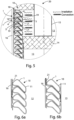
- FIG 2 it is noted a cross section of a heat exchanger obtained by the profile 1 according to the invention and indicated by reference number 10.
- the heat exchanger 10 of the condensation boiler 20 comprises the profile 1, spirally arranged about a central axis y, in particular a vertical axis, so as to have a plurality of coils 11 wound one over the other with respect to said central axis y.
- These coils 11 are arranged in such a way as to present the first base 4 of the trapezoidal portion 2 of the profile 1 of each coil 11 inclined with respect to the central axis y of a fourth angle ⁇ ranging between 10° and 60°, preferably about 45° as shown in figure 2 .
- the configuration of the heat exchanger 10 thus obtained allows to channel the combustion gases of a condensation boiler in which the heat exchanger 10 could be inserted, facilitating their ascent, increasing the thermal contact surface and facilitating the descent of eventual condensation liquids formed by the change of angles of the created path.
- said coils 11 can be spaced one 11 from the other 11' so as to have the basis 4', 5 of the trapezoidal portion 2 and 2' of the cross section of the respective profile 1, 1' between them parallel and spaced apart by a distance dx ranging between 0.5 mm and 2 mm.
- Said boiler 20 provides a heat exchanger 10 as described in the above.
- condensation boiler 20 has a combustion zone 12, a condensation zone 13, and a dividing wall 14, preferably comprised of refractory and insulating material, between said two zones 12 and 13.
- the heat exchanger 10 of the boiler 20 according to the invention has a profile 1 such as to be advantageous for use both in the combustion zone 12 and in the condensation zone 13.
- the boiler 20 also comprises, in the combustion zone 12, a burner 15 designed to heat by irradiation the fluid flowing in the heat exchanger 10 and an external casing 16, able to contain the fumes inside the heat exchanger 10.
- the profile 1 according to the invention has been studied so that the fumes are conveyed in the channel 19 between two successive coils 11 through a converging zone, in which the decrease of section allows to increase the speed of the fumes while crossing the interspace or channel 19 consequently increasing the thermal exchange of convective type.
- the diverging zone of channel 19 allows the separation of the fumes from the condensate formed (in some operating conditions, condensation can occur in the inclination change zone), so that the fumes do not have the passage obstructed and therefore not there is not a burden of load losses.
- the tube profile "P" and the distance between the coils 11 are designed in such a way to maximize the thermal exchange maintaining pressure losses
- the angle of the profile 1 with respect to the central axis y of the heat exchanger 10, determined by the fourth angle ⁇ , allows to obtain a difference in height between the lowest point 17 of a coil 11 and the highest point 18'of the next coil 11', located immediately below, in such a way as to prevent that the irradiation light of the burner 15 reaches the outer casing 16.
- the overlap of the coils 11 of the heat exchanger 10 of the boiler 20 according to the invention it ensures the shielding of the casing 16 from the radiation generated by the burner 15.
- the difference of gradient that is formed in the channel passage 19 between one coil 11 and the other 11' facilitates, in the ascending portion, the ascent of the combustion fumes and the heat exchange with the heat exchanger surface 10 and, in the descending path, the downward descent, and then towards the condensation zone of the condensate that was formed during the heat exchange of the fume gases with the heat exchanger surface 10, preventing falling into the combustion zone 12.
- the distance dy between the outer casing of the boiler 20 and the heat exchanger is between 0.1 mm and 20 mm. This advantageously allows the passage of the fume gases which, in contact with the casing 16, they cool and then condense and fall down. In addition, said distance dy also allows the outer portion of the profile 1 to participate in the heat exchange with the combustion fumes.
- a slotted shirt 21 between the casing 16 and the heat exchanger 10 can be provided a slotted shirt 21 between the casing 16 and the heat exchanger 10, both in correspondence with the combustion zone 12 and of the condensation zone 13 or, in one of them, for obtaining a better distribution of the flow and a better heat exchange.
- the openings may be constant or variable for a better balancing of the flow.
- the shape of the coils 11 profile 1 of the heat exchanger 10 is also advantageous in correspondence with the condensation zone 13, as the condensation liquid is made descending through the channel 19 formed between two coils 11 and 11', thus being countercurrent with respect to the condensate droplet.
- the condensation liquid having a higher temperature than the fluid flowing in the heat exchanger 10 allows a pre-heating of the same through the heat exchange that takes place during its descent towards the condensation zone 13.
- the distance dz between the heat exchanger 10 by the dividing wall 14 is between 0.1 mm and 20 mm. This distance allows drainage of the condensate in correspondence of the condensation zone 13 and a better and efficient heat exchange.
- the condensation boiler 20 according to a preferred embodiment of the invention has the height of the combustion chamber 12 ranging between 30% and 65% of the height of the boiler 20.
- the last coil can be closed, thus preventing the passage of the fumes (shown with arrows), so as to force them to lap the entire surface of the heat exchanger 10.
- the heat exchanger can also be used in a condensation boiler 20 of the horizontal type.
- the boiler must be oriented so that the central axis y of the heat exchanger 10 is arranged vertically, or inclined between 4° and 90°.
Claims (9)
- Chaudière à condensation (20) comprenant un échangeur de chaleur à serpentin (10) comprenant un profilé (1) de tuyauterie disposé en spirale de manière à comprendre une pluralité de serpentins (11) enroulés les uns sur les autres par rapport à un axe central (y), ladite chaudière à condensation (20) étant caractérisée en ce que ledit profilé (1) présente une section transversale sensiblement en forme de "P", dans lequel la section transversale du profilé (1) présente une partie trapézoïdale (2), avec deux bases (4, 5) et deux côtés (6, 7), et une partie triangulaire (3), avec une base (6) et deux côtés (8, 9), dans lequel un premier côté (6) de la partie trapézoïdale (2) coïncide avec la base (6) de la partie triangulaire (3), dans lequel le deuxième côté (7) et les bases (4, 5) de la partie trapézoïdale et les côtés (8, 9) de la partie triangulaire (3) forment les parois intérieures du profilé (1), dans lequel un premier angle (α) entre la première base (4) de la partie trapézoïdale (2) et le premier côté (8) de la partie triangulaire (3) qui lui est adjacente est d'environ 90°, dans lequel un deuxième angle (β) entre la deuxième base (5) de la partie trapézoïdale (2) et le deuxième côté (9) de la partie triangulaire (3) qui lui est adjacente est d'environ 225°, dans lequel la première base (4) de la partie trapézoïdale (2) de la section transversale du profilé (1) de chaque serpentin (11) est inclinée par rapport à l'axe central (y) d'un quatrième angle (δ) compris entre 10° et 60°, de préférence de 45°.
- Chaudière à condensation (20) selon la revendication précédente, dans lequel un troisième angle (γ) entre la première base (4) et le deuxième côté (7) de la partie trapézoïdale de la section transversale du profilé (1) est compris entre 120° et 170°.
- Chaudière à condensation (20) selon l'une quelconque des revendications précédentes 1 ou 2, caractérisée par le fait que les angles (α, β, γ) du profilé (1) sont lissés.
- Chaudière à condensation (20) selon l'une quelconque des revendications précédentes, caractérisée en ce que lesdits serpentins (11) de l'échangeur de chaleur (10) sont disposés de manière à ce que la deuxième base (5) de la partie trapézoïdale (2) de la section du profilé (1) d'un premier serpentin (11) soit parallèle à la première base (4') de la partie trapézoïdale (2') de la section du profilé (1') d'un serpentin (11') adjacent et séparé d'une distance (dx) comprise entre 0.5 mm et 2 mm.
- Chaudière à condensation (20) selon l'une quelconque des revendications précédentes, caractérisée en ce qu'elle comprend une zone de combustion (12), une zone de condensation (13), et une paroi de séparation (14) entre lesdites deux zones (12, 13), en ce qu'en correspondance de ladite zone de condensation (13) lesdits serpentins (11) sont éloignés de ladite paroi de séparation (14) d'une distance (dz) comprise entre 0,1 mm et 20 mm.
- Chaudière à condensation (20) selon l'une quelconque des revendications précédentes, caractérisée en ce qu'elle comprend une enveloppe externe (16) et en ce que chacun desdits serpentins (11) est éloigné de ladite enveloppe externe (16) d'une distance (dy) comprise entre 0,1 mm et 20 mm.
- Chaudière à condensation (20) selon la revendication précédente, caractérisée par la présence d'une chemise fendue (21) entre ladite enveloppe externe (16) et ledit échangeur de chaleur (10) en correspondance de ladite zone de combustion (12) et/ou de ladite zone de condensation (13).
- Chaudière à condensation (20) selon l'une des revendications 5 à 7, lorsqu'elle dépend de la revendication 5, caractérisée par le fait que la hauteur de ladite zone de combustion (12) est comprise entre 30% et 65% de la hauteur de la chaudière (20).
- Chaudière à condensation (20) selon l'une quelconque des revendications précédentes, caractérisée en ce qu'elle est orientée de telle sorte que l'axe central (γ) de l'échangeur de chaleur (10) est disposé verticalement ou incliné d'une inclinaison comprise entre 4° et 90°.
Applications Claiming Priority (2)
| Application Number | Priority Date | Filing Date | Title |
|---|---|---|---|
| ITUB20151634 | 2015-06-24 | ||
| PCT/IT2016/000161 WO2016207923A1 (fr) | 2015-06-24 | 2016-06-21 | Profil de tube pour échangeur de chaleur, échangeur de chaleur pour chaudières à condensation présentant ledit profil, et chaudière à condensation équipée dudit échangeur de chaleur |
Publications (2)
| Publication Number | Publication Date |
|---|---|
| EP3314174A1 EP3314174A1 (fr) | 2018-05-02 |
| EP3314174B1 true EP3314174B1 (fr) | 2023-08-02 |
Family
ID=54251612
Family Applications (1)
| Application Number | Title | Priority Date | Filing Date |
|---|---|---|---|
| EP16770372.7A Active EP3314174B1 (fr) | 2015-06-24 | 2016-06-21 | Chaudière à condensation comportant un échangeur de chaleur enroulé avec une tuyauterie disposée en spirale |
Country Status (7)
| Country | Link |
|---|---|
| US (1) | US11041659B2 (fr) |
| EP (1) | EP3314174B1 (fr) |
| CN (1) | CN108291739B (fr) |
| CA (1) | CA2990138A1 (fr) |
| HK (1) | HK1252491A1 (fr) |
| RU (1) | RU2685759C1 (fr) |
| WO (1) | WO2016207923A1 (fr) |
Families Citing this family (3)
| Publication number | Priority date | Publication date | Assignee | Title |
|---|---|---|---|---|
| FR3088995B1 (fr) * | 2018-11-26 | 2020-12-04 | Arianegroup Sas | Serpentin pour echangeur thermique, echappement de turbopompe comprenant un serpentin et procede de fabrication d’un serpentin |
| US11761677B2 (en) * | 2019-12-04 | 2023-09-19 | A. O. Smith Corporation | Water heater having highly efficient and compact heat exchanger |
| RU2760544C1 (ru) * | 2020-06-05 | 2021-11-26 | Общество с ограниченной ответственность "Теплогазстрой" | Спиральный котёл |
Family Cites Families (17)
| Publication number | Priority date | Publication date | Assignee | Title |
|---|---|---|---|---|
| US910192A (en) * | 1906-04-27 | 1909-01-19 | Philippe Jules Grouvelle | Tube. |
| SU533810A1 (ru) * | 1973-01-02 | 1976-10-30 | Плавникова труба | |
| SU1765672A1 (ru) * | 1986-12-16 | 1992-09-30 | Производственное объединение "Невский завод" им.В.И.Ленина | Кожухотрубный теплообменник |
| EP0745813A3 (fr) * | 1995-05-31 | 1997-12-29 | VIESSMANN WERKE GmbH & CO. | Echangeur de chaleur, en particulier pour chaudière |
| NL1005649C2 (nl) * | 1997-03-26 | 1998-09-29 | Fasto Nefit Bv | Warmtewisselaar, en buis voor de vervaardiging van een dergelijke warmtewisselaar. |
| AT406907B (de) * | 1999-01-21 | 2000-10-25 | Vaillant Gmbh | Wasserheizer |
| WO2005108875A1 (fr) * | 2004-05-11 | 2005-11-17 | Noritz Corporation | Échangeur de chaleur et dispositif chauffe-eau |
| JP2005321170A (ja) * | 2004-05-11 | 2005-11-17 | Noritz Corp | 瞬間式加熱装置および給湯装置 |
| EA200500565A1 (ru) * | 2005-02-23 | 2006-06-30 | Андрей Дмитриевич Тюменцев | Способ изготовления трубчатого теплообменного элемента и трубчатый теплообменный элемент |
| ES2348581T3 (es) * | 2005-08-05 | 2010-12-09 | Riello S.P.A. | Método de fabricación de un intercambiador de calor. |
| CN200961869Y (zh) * | 2006-09-29 | 2007-10-17 | 成都前锋热交换器有限责任公司 | 冷凝式热交换器 |
| DE102008012126A1 (de) * | 2008-03-01 | 2009-09-10 | Robert Bosch Gmbh | Heizgerät |
| WO2011002711A1 (fr) * | 2009-06-29 | 2011-01-06 | Laars Heating Systems Company | Echangeur de chaleur à tube plat pour chaudières et chauffe-eau |
| IT1396729B1 (it) * | 2009-11-24 | 2012-12-14 | Fontecal S P A | Scambiatore a condensazione a doppia tubazione per riscaldamento di acqua e/o produzione di acqua calda sanitaria . |
| FR2955929B1 (fr) * | 2010-02-01 | 2014-04-18 | Mer Joseph Le | Echangeur de chaleur a condensation pour plusieurs fluides et dispositif de production de fluides chauds comprenant un tel echangeur |
| CN203928415U (zh) * | 2014-07-12 | 2014-11-05 | 中山市健泰实业有限公司 | 一种暖炉热交换盘管 |
| US10024603B2 (en) * | 2014-11-26 | 2018-07-17 | Riello S.P.A. | Double tubing condensation exchanger for heating water and/or for producing sanitary hot water |
-
2016
- 2016-06-21 CA CA2990138A patent/CA2990138A1/fr active Pending
- 2016-06-21 US US15/738,336 patent/US11041659B2/en active Active
- 2016-06-21 WO PCT/IT2016/000161 patent/WO2016207923A1/fr active Application Filing
- 2016-06-21 EP EP16770372.7A patent/EP3314174B1/fr active Active
- 2016-06-21 CN CN201680036817.1A patent/CN108291739B/zh active Active
- 2016-06-21 RU RU2017146085A patent/RU2685759C1/ru active
-
2018
- 2018-09-13 HK HK18111800A patent/HK1252491A1/zh unknown
Also Published As
| Publication number | Publication date |
|---|---|
| CN108291739A (zh) | 2018-07-17 |
| CA2990138A1 (fr) | 2016-12-29 |
| HK1252491A1 (zh) | 2019-05-31 |
| RU2685759C1 (ru) | 2019-04-23 |
| WO2016207923A1 (fr) | 2016-12-29 |
| US20180172313A1 (en) | 2018-06-21 |
| EP3314174A1 (fr) | 2018-05-02 |
| CN108291739B (zh) | 2020-06-05 |
| US11041659B2 (en) | 2021-06-22 |
Similar Documents
| Publication | Publication Date | Title |
|---|---|---|
| EP3314174B1 (fr) | Chaudière à condensation comportant un échangeur de chaleur enroulé avec une tuyauterie disposée en spirale | |
| US20030006030A1 (en) | Heat exchanger tube with integral restricting and turbulating structure | |
| KR101688934B1 (ko) | 결합식 가스관-수관 혼합형 열교환기 | |
| US20110203781A1 (en) | Multiple-ring heat exchanger | |
| CN100462628C (zh) | 用于密封的燃烧室的导流板 | |
| CN107429942B (zh) | 用于加热水和/或用于生产家用热水的双盘管冷凝热交换器 | |
| US20100162967A1 (en) | Heat exchanger | |
| ES2820826T3 (es) | Intercambiador de calor de combustión | |
| US20120145373A1 (en) | Firetube having thermal conducting passageways | |
| US20190017753A1 (en) | Heat exchanger tube | |
| RU178049U1 (ru) | Подогреватель | |
| KR20080081805A (ko) | 스팀 생성기 파이프 및 그 생산 방법, 그리고 연속적인스팀 생성기 | |
| EP2504632B1 (fr) | Echangeur condenseur à double tubage pour chauffer de l'eau et/ou produire de l'eau chaude sanitaire | |
| JP2010085036A (ja) | 熱交換器および温水装置 | |
| US3378064A (en) | Tube support | |
| RU69198U1 (ru) | Подогреватель | |
| CN207066203U (zh) | 一种板管式空气预热器 | |
| CN104266493A (zh) | 等温度换热管辐射式电加热器 | |
| JP2016023872A (ja) | 熱交換器 | |
| EP3426986B1 (fr) | Échangeur de chaleur sectionnel à utiliser dans une cellule thermique | |
| JP3196892U (ja) | マルチパス型多管式貫流ボイラ | |
| RU15576U1 (ru) | Конвекторное кольцо колпаковой печи | |
| JP5575438B2 (ja) | 流体加熱装置 | |
| JP5457145B2 (ja) | 流体加熱装置 | |
| JP2017020709A (ja) | 給水予熱装置を持ったボイラ |
Legal Events
| Date | Code | Title | Description |
|---|---|---|---|
| STAA | Information on the status of an ep patent application or granted ep patent |
Free format text: STATUS: THE INTERNATIONAL PUBLICATION HAS BEEN MADE |
|
| PUAI | Public reference made under article 153(3) epc to a published international application that has entered the european phase |
Free format text: ORIGINAL CODE: 0009012 |
|
| STAA | Information on the status of an ep patent application or granted ep patent |
Free format text: STATUS: REQUEST FOR EXAMINATION WAS MADE |
|
| 17P | Request for examination filed |
Effective date: 20180109 |
|
| AK | Designated contracting states |
Kind code of ref document: A1 Designated state(s): AL AT BE BG CH CY CZ DE DK EE ES FI FR GB GR HR HU IE IS IT LI LT LU LV MC MK MT NL NO PL PT RO RS SE SI SK SM TR |
|
| AX | Request for extension of the european patent |
Extension state: BA ME |
|
| DAV | Request for validation of the european patent (deleted) | ||
| DAX | Request for extension of the european patent (deleted) | ||
| STAA | Information on the status of an ep patent application or granted ep patent |
Free format text: STATUS: EXAMINATION IS IN PROGRESS |
|
| 17Q | First examination report despatched |
Effective date: 20210510 |
|
| STAA | Information on the status of an ep patent application or granted ep patent |
Free format text: STATUS: EXAMINATION IS IN PROGRESS |
|
| GRAP | Despatch of communication of intention to grant a patent |
Free format text: ORIGINAL CODE: EPIDOSNIGR1 |
|
| STAA | Information on the status of an ep patent application or granted ep patent |
Free format text: STATUS: GRANT OF PATENT IS INTENDED |
|
| RIC1 | Information provided on ipc code assigned before grant |
Ipc: F28F 17/00 20060101ALI20230315BHEP Ipc: F28F 1/02 20060101ALI20230315BHEP Ipc: F28D 7/02 20060101ALI20230315BHEP Ipc: F24H 8/00 20060101ALI20230315BHEP Ipc: F24H 1/16 20060101ALI20230315BHEP Ipc: F24H 1/44 20060101ALI20230315BHEP Ipc: F24H 1/43 20060101AFI20230315BHEP |
|
| INTG | Intention to grant announced |
Effective date: 20230405 |
|
| GRAS | Grant fee paid |
Free format text: ORIGINAL CODE: EPIDOSNIGR3 |
|
| GRAA | (expected) grant |
Free format text: ORIGINAL CODE: 0009210 |
|
| STAA | Information on the status of an ep patent application or granted ep patent |
Free format text: STATUS: THE PATENT HAS BEEN GRANTED |
|
| RIN1 | Information on inventor provided before grant (corrected) |
Inventor name: IACHINI, GIANLUCA Inventor name: DE NARDIS, MARCO |
|
| P01 | Opt-out of the competence of the unified patent court (upc) registered |
Effective date: 20230529 |
|
| AK | Designated contracting states |
Kind code of ref document: B1 Designated state(s): AL AT BE BG CH CY CZ DE DK EE ES FI FR GB GR HR HU IE IS IT LI LT LU LV MC MK MT NL NO PL PT RO RS SE SI SK SM TR |
|
| REG | Reference to a national code |
Ref country code: GB Ref legal event code: FG4D |
|
| REG | Reference to a national code |
Ref country code: CH Ref legal event code: EP |
|
| REG | Reference to a national code |
Ref country code: DE Ref legal event code: R096 Ref document number: 602016081586 Country of ref document: DE |
|
| REG | Reference to a national code |
Ref country code: IE Ref legal event code: FG4D |
|
| REG | Reference to a national code |
Ref country code: LT Ref legal event code: MG9D |
|
| REG | Reference to a national code |
Ref country code: NL Ref legal event code: MP Effective date: 20230802 |
|
| REG | Reference to a national code |
Ref country code: AT Ref legal event code: MK05 Ref document number: 1595184 Country of ref document: AT Kind code of ref document: T Effective date: 20230802 |
|
| PG25 | Lapsed in a contracting state [announced via postgrant information from national office to epo] |
Ref country code: GR Free format text: LAPSE BECAUSE OF FAILURE TO SUBMIT A TRANSLATION OF THE DESCRIPTION OR TO PAY THE FEE WITHIN THE PRESCRIBED TIME-LIMIT Effective date: 20231103 |
|
| PG25 | Lapsed in a contracting state [announced via postgrant information from national office to epo] |
Ref country code: IS Free format text: LAPSE BECAUSE OF FAILURE TO SUBMIT A TRANSLATION OF THE DESCRIPTION OR TO PAY THE FEE WITHIN THE PRESCRIBED TIME-LIMIT Effective date: 20231202 |
|
| PG25 | Lapsed in a contracting state [announced via postgrant information from national office to epo] |
Ref country code: SE Free format text: LAPSE BECAUSE OF FAILURE TO SUBMIT A TRANSLATION OF THE DESCRIPTION OR TO PAY THE FEE WITHIN THE PRESCRIBED TIME-LIMIT Effective date: 20230802 Ref country code: RS Free format text: LAPSE BECAUSE OF FAILURE TO SUBMIT A TRANSLATION OF THE DESCRIPTION OR TO PAY THE FEE WITHIN THE PRESCRIBED TIME-LIMIT Effective date: 20230802 Ref country code: PT Free format text: LAPSE BECAUSE OF FAILURE TO SUBMIT A TRANSLATION OF THE DESCRIPTION OR TO PAY THE FEE WITHIN THE PRESCRIBED TIME-LIMIT Effective date: 20231204 Ref country code: NO Free format text: LAPSE BECAUSE OF FAILURE TO SUBMIT A TRANSLATION OF THE DESCRIPTION OR TO PAY THE FEE WITHIN THE PRESCRIBED TIME-LIMIT Effective date: 20231102 Ref country code: NL Free format text: LAPSE BECAUSE OF FAILURE TO SUBMIT A TRANSLATION OF THE DESCRIPTION OR TO PAY THE FEE WITHIN THE PRESCRIBED TIME-LIMIT Effective date: 20230802 Ref country code: LV Free format text: LAPSE BECAUSE OF FAILURE TO SUBMIT A TRANSLATION OF THE DESCRIPTION OR TO PAY THE FEE WITHIN THE PRESCRIBED TIME-LIMIT Effective date: 20230802 Ref country code: LT Free format text: LAPSE BECAUSE OF FAILURE TO SUBMIT A TRANSLATION OF THE DESCRIPTION OR TO PAY THE FEE WITHIN THE PRESCRIBED TIME-LIMIT Effective date: 20230802 Ref country code: IS Free format text: LAPSE BECAUSE OF FAILURE TO SUBMIT A TRANSLATION OF THE DESCRIPTION OR TO PAY THE FEE WITHIN THE PRESCRIBED TIME-LIMIT Effective date: 20231202 Ref country code: HR Free format text: LAPSE BECAUSE OF FAILURE TO SUBMIT A TRANSLATION OF THE DESCRIPTION OR TO PAY THE FEE WITHIN THE PRESCRIBED TIME-LIMIT Effective date: 20230802 Ref country code: GR Free format text: LAPSE BECAUSE OF FAILURE TO SUBMIT A TRANSLATION OF THE DESCRIPTION OR TO PAY THE FEE WITHIN THE PRESCRIBED TIME-LIMIT Effective date: 20231103 Ref country code: FI Free format text: LAPSE BECAUSE OF FAILURE TO SUBMIT A TRANSLATION OF THE DESCRIPTION OR TO PAY THE FEE WITHIN THE PRESCRIBED TIME-LIMIT Effective date: 20230802 Ref country code: AT Free format text: LAPSE BECAUSE OF FAILURE TO SUBMIT A TRANSLATION OF THE DESCRIPTION OR TO PAY THE FEE WITHIN THE PRESCRIBED TIME-LIMIT Effective date: 20230802 |
|
| PG25 | Lapsed in a contracting state [announced via postgrant information from national office to epo] |
Ref country code: PL Free format text: LAPSE BECAUSE OF FAILURE TO SUBMIT A TRANSLATION OF THE DESCRIPTION OR TO PAY THE FEE WITHIN THE PRESCRIBED TIME-LIMIT Effective date: 20230802 |
|
| PG25 | Lapsed in a contracting state [announced via postgrant information from national office to epo] |
Ref country code: ES Free format text: LAPSE BECAUSE OF FAILURE TO SUBMIT A TRANSLATION OF THE DESCRIPTION OR TO PAY THE FEE WITHIN THE PRESCRIBED TIME-LIMIT Effective date: 20230802 |
|
| PG25 | Lapsed in a contracting state [announced via postgrant information from national office to epo] |
Ref country code: SM Free format text: LAPSE BECAUSE OF FAILURE TO SUBMIT A TRANSLATION OF THE DESCRIPTION OR TO PAY THE FEE WITHIN THE PRESCRIBED TIME-LIMIT Effective date: 20230802 Ref country code: RO Free format text: LAPSE BECAUSE OF FAILURE TO SUBMIT A TRANSLATION OF THE DESCRIPTION OR TO PAY THE FEE WITHIN THE PRESCRIBED TIME-LIMIT Effective date: 20230802 Ref country code: ES Free format text: LAPSE BECAUSE OF FAILURE TO SUBMIT A TRANSLATION OF THE DESCRIPTION OR TO PAY THE FEE WITHIN THE PRESCRIBED TIME-LIMIT Effective date: 20230802 Ref country code: EE Free format text: LAPSE BECAUSE OF FAILURE TO SUBMIT A TRANSLATION OF THE DESCRIPTION OR TO PAY THE FEE WITHIN THE PRESCRIBED TIME-LIMIT Effective date: 20230802 Ref country code: DK Free format text: LAPSE BECAUSE OF FAILURE TO SUBMIT A TRANSLATION OF THE DESCRIPTION OR TO PAY THE FEE WITHIN THE PRESCRIBED TIME-LIMIT Effective date: 20230802 Ref country code: CZ Free format text: LAPSE BECAUSE OF FAILURE TO SUBMIT A TRANSLATION OF THE DESCRIPTION OR TO PAY THE FEE WITHIN THE PRESCRIBED TIME-LIMIT Effective date: 20230802 Ref country code: SK Free format text: LAPSE BECAUSE OF FAILURE TO SUBMIT A TRANSLATION OF THE DESCRIPTION OR TO PAY THE FEE WITHIN THE PRESCRIBED TIME-LIMIT Effective date: 20230802 |