EP3311967A1 - Woodworking device - Google Patents
Woodworking device Download PDFInfo
- Publication number
- EP3311967A1 EP3311967A1 EP17194866.4A EP17194866A EP3311967A1 EP 3311967 A1 EP3311967 A1 EP 3311967A1 EP 17194866 A EP17194866 A EP 17194866A EP 3311967 A1 EP3311967 A1 EP 3311967A1
- Authority
- EP
- European Patent Office
- Prior art keywords
- shaft portion
- tool head
- transmission
- drive
- axis
- Prior art date
- Legal status (The legal status is an assumption and is not a legal conclusion. Google has not performed a legal analysis and makes no representation as to the accuracy of the status listed.)
- Granted
Links
- 230000005540 biological transmission Effects 0.000 claims abstract description 59
- 230000033001 locomotion Effects 0.000 claims abstract description 18
- 239000002023 wood Substances 0.000 claims description 24
- 238000003754 machining Methods 0.000 description 6
- 238000012423 maintenance Methods 0.000 description 2
- 238000003801 milling Methods 0.000 description 2
- 230000001419 dependent effect Effects 0.000 description 1
- 238000005553 drilling Methods 0.000 description 1
- 239000000428 dust Substances 0.000 description 1
- 238000000605 extraction Methods 0.000 description 1
- 230000002452 interceptive effect Effects 0.000 description 1
- 230000000087 stabilizing effect Effects 0.000 description 1
Images


Classifications
-
- B—PERFORMING OPERATIONS; TRANSPORTING
- B27—WORKING OR PRESERVING WOOD OR SIMILAR MATERIAL; NAILING OR STAPLING MACHINES IN GENERAL
- B27C—PLANING, DRILLING, MILLING, TURNING OR UNIVERSAL MACHINES FOR WOOD OR SIMILAR MATERIAL
- B27C9/00—Multi-purpose machines; Universal machines; Equipment therefor
-
- B—PERFORMING OPERATIONS; TRANSPORTING
- B27—WORKING OR PRESERVING WOOD OR SIMILAR MATERIAL; NAILING OR STAPLING MACHINES IN GENERAL
- B27M—WORKING OF WOOD NOT PROVIDED FOR IN SUBCLASSES B27B - B27L; MANUFACTURE OF SPECIFIC WOODEN ARTICLES
- B27M1/00—Working of wood not provided for in subclasses B27B - B27L, e.g. by stretching
- B27M1/08—Working of wood not provided for in subclasses B27B - B27L, e.g. by stretching by multi-step processes
-
- B—PERFORMING OPERATIONS; TRANSPORTING
- B23—MACHINE TOOLS; METAL-WORKING NOT OTHERWISE PROVIDED FOR
- B23Q—DETAILS, COMPONENTS, OR ACCESSORIES FOR MACHINE TOOLS, e.g. ARRANGEMENTS FOR COPYING OR CONTROLLING; MACHINE TOOLS IN GENERAL CHARACTERISED BY THE CONSTRUCTION OF PARTICULAR DETAILS OR COMPONENTS; COMBINATIONS OR ASSOCIATIONS OF METAL-WORKING MACHINES, NOT DIRECTED TO A PARTICULAR RESULT
- B23Q1/00—Members which are comprised in the general build-up of a form of machine, particularly relatively large fixed members
- B23Q1/25—Movable or adjustable work or tool supports
- B23Q1/44—Movable or adjustable work or tool supports using particular mechanisms
- B23Q1/50—Movable or adjustable work or tool supports using particular mechanisms with rotating pairs only, the rotating pairs being the first two elements of the mechanism
- B23Q1/54—Movable or adjustable work or tool supports using particular mechanisms with rotating pairs only, the rotating pairs being the first two elements of the mechanism two rotating pairs only
- B23Q1/5468—Movable or adjustable work or tool supports using particular mechanisms with rotating pairs only, the rotating pairs being the first two elements of the mechanism two rotating pairs only a single rotating pair followed parallelly by a single rotating pair
-
- B—PERFORMING OPERATIONS; TRANSPORTING
- B23—MACHINE TOOLS; METAL-WORKING NOT OTHERWISE PROVIDED FOR
- B23Q—DETAILS, COMPONENTS, OR ACCESSORIES FOR MACHINE TOOLS, e.g. ARRANGEMENTS FOR COPYING OR CONTROLLING; MACHINE TOOLS IN GENERAL CHARACTERISED BY THE CONSTRUCTION OF PARTICULAR DETAILS OR COMPONENTS; COMBINATIONS OR ASSOCIATIONS OF METAL-WORKING MACHINES, NOT DIRECTED TO A PARTICULAR RESULT
- B23Q39/00—Metal-working machines incorporating a plurality of sub-assemblies, each capable of performing a metal-working operation
- B23Q39/02—Metal-working machines incorporating a plurality of sub-assemblies, each capable of performing a metal-working operation the sub-assemblies being capable of being brought to act at a single operating station
- B23Q39/021—Metal-working machines incorporating a plurality of sub-assemblies, each capable of performing a metal-working operation the sub-assemblies being capable of being brought to act at a single operating station with a plurality of toolheads per workholder, whereby the toolhead is a main spindle, a multispindle, a revolver or the like
- B23Q39/022—Metal-working machines incorporating a plurality of sub-assemblies, each capable of performing a metal-working operation the sub-assemblies being capable of being brought to act at a single operating station with a plurality of toolheads per workholder, whereby the toolhead is a main spindle, a multispindle, a revolver or the like with same working direction of toolheads on same workholder
- B23Q39/024—Metal-working machines incorporating a plurality of sub-assemblies, each capable of performing a metal-working operation the sub-assemblies being capable of being brought to act at a single operating station with a plurality of toolheads per workholder, whereby the toolhead is a main spindle, a multispindle, a revolver or the like with same working direction of toolheads on same workholder consecutive working of toolheads
-
- B—PERFORMING OPERATIONS; TRANSPORTING
- B23—MACHINE TOOLS; METAL-WORKING NOT OTHERWISE PROVIDED FOR
- B23Q—DETAILS, COMPONENTS, OR ACCESSORIES FOR MACHINE TOOLS, e.g. ARRANGEMENTS FOR COPYING OR CONTROLLING; MACHINE TOOLS IN GENERAL CHARACTERISED BY THE CONSTRUCTION OF PARTICULAR DETAILS OR COMPONENTS; COMBINATIONS OR ASSOCIATIONS OF METAL-WORKING MACHINES, NOT DIRECTED TO A PARTICULAR RESULT
- B23Q39/00—Metal-working machines incorporating a plurality of sub-assemblies, each capable of performing a metal-working operation
- B23Q39/02—Metal-working machines incorporating a plurality of sub-assemblies, each capable of performing a metal-working operation the sub-assemblies being capable of being brought to act at a single operating station
- B23Q39/021—Metal-working machines incorporating a plurality of sub-assemblies, each capable of performing a metal-working operation the sub-assemblies being capable of being brought to act at a single operating station with a plurality of toolheads per workholder, whereby the toolhead is a main spindle, a multispindle, a revolver or the like
- B23Q39/025—Metal-working machines incorporating a plurality of sub-assemblies, each capable of performing a metal-working operation the sub-assemblies being capable of being brought to act at a single operating station with a plurality of toolheads per workholder, whereby the toolhead is a main spindle, a multispindle, a revolver or the like with different working directions of toolheads on same workholder
- B23Q39/027—Metal-working machines incorporating a plurality of sub-assemblies, each capable of performing a metal-working operation the sub-assemblies being capable of being brought to act at a single operating station with a plurality of toolheads per workholder, whereby the toolhead is a main spindle, a multispindle, a revolver or the like with different working directions of toolheads on same workholder consecutive working of toolheads
-
- B—PERFORMING OPERATIONS; TRANSPORTING
- B23—MACHINE TOOLS; METAL-WORKING NOT OTHERWISE PROVIDED FOR
- B23Q—DETAILS, COMPONENTS, OR ACCESSORIES FOR MACHINE TOOLS, e.g. ARRANGEMENTS FOR COPYING OR CONTROLLING; MACHINE TOOLS IN GENERAL CHARACTERISED BY THE CONSTRUCTION OF PARTICULAR DETAILS OR COMPONENTS; COMBINATIONS OR ASSOCIATIONS OF METAL-WORKING MACHINES, NOT DIRECTED TO A PARTICULAR RESULT
- B23Q5/00—Driving or feeding mechanisms; Control arrangements therefor
- B23Q5/02—Driving main working members
- B23Q5/04—Driving main working members rotary shafts, e.g. working-spindles
- B23Q5/043—Accessories for spindle drives
- B23Q5/045—Angle drives
-
- B—PERFORMING OPERATIONS; TRANSPORTING
- B23—MACHINE TOOLS; METAL-WORKING NOT OTHERWISE PROVIDED FOR
- B23Q—DETAILS, COMPONENTS, OR ACCESSORIES FOR MACHINE TOOLS, e.g. ARRANGEMENTS FOR COPYING OR CONTROLLING; MACHINE TOOLS IN GENERAL CHARACTERISED BY THE CONSTRUCTION OF PARTICULAR DETAILS OR COMPONENTS; COMBINATIONS OR ASSOCIATIONS OF METAL-WORKING MACHINES, NOT DIRECTED TO A PARTICULAR RESULT
- B23Q5/00—Driving or feeding mechanisms; Control arrangements therefor
- B23Q5/02—Driving main working members
- B23Q5/04—Driving main working members rotary shafts, e.g. working-spindles
- B23Q5/043—Accessories for spindle drives
- B23Q5/046—Offset spindle drives
Definitions
- the invention relates to woodworking devices according to the preamble of claim 1.
- These woodworking devices are used for the machining of wood elements performed with different tools and they comprise at least one aggregate with at least one change-over chuck for tools or tool holders.
- tools are used for sawing, drilling, milling, planing, throats or grooves.
- the unit can align an inserted tool in a direction desired for the machining of a wooden element and set in rotation for machining.
- the woodworking device comprises a guide device.
- the guide device comprises an assembly guide for moving the unit and / or an element guide for moving the wood element.
- EP 2 353 820 B1 and EP 0 608 746 B1 describe solutions in which a spindle motor with a chuck for tools rotatable relative to a support of rotating devices about two mutually perpendicular axes of rotation and the carrier is slidably mounted in two directions designated y and z mutually perpendicular directions.
- a wooden beam to be machined is positionable in a direction indicated by x, this x-direction being perpendicular to the plane defined by the y and z directions.
- WO 2008/004263 A2 and WO 2004/080649 A1 describe a displaceable working unit having a z-axis rotatable intermediate piece and a rotatable about an axis perpendicular to the z-axis housing with three or more spindle motors, each of which can drive a tool. It can only bolt-shaped tools are rotated with the housing. Again, cable guides to the spindle motors limit the possibilities of movement and the forces necessary for rapid alignment changes and the space required for the Drehausrhythm the spindle motors are undesirably large.
- the object of the invention is now to find a simply constructed and efficiently working woodworking device.
- An inventive woodworking device for processing wooden elements comprises at least one unit and a guide device, wherein the guide device is capable of bringing the at least one unit and a wood element to be processed into a desired relative position.
- the at least one unit comprises a connecting device to the guide device, for example a displaceable in the y- and z-direction base plate, a tool head with at least one change chuck for tools or tool holder and between the connecting device and the tool head in the connecting device a first and the tool head a second rotating device for rotational movements about a first or a second axis of rotation, wherein the first and the second axis of rotation are aligned perpendicular to each other.
- the unit also comprises unit parts or housing parts on which elements of the unit are arranged.
- the drive motor for providing the rotary movement for working tools is not arranged directly at the exchangeable chuck for the tools or tool holders, but at the connecting device.
- the drive device for driving the at least one change-over chuck in addition to the drive motor, to additionally comprise a drive transmission from the drive motor to the at least one change chuck of the tool head.
- the drive transmission in the first and the second rotating device each comprises a centered on the first and second axis of rotation arranged first and second shaft portion and the tool head remote from the second shaft portion a positive gear with gears , preferably with two intermeshing bevel gears.
- the tool head can be built extremely small.
- the drive transmission of the first shaft portion is connected via two bevel gears with the second shaft portion.
- a positive gear with other gears and possibly at least one further shaft portion is used.
- the drive transmission via gears with gears and shafts can be made compact and it is associated with a minimum of maintenance.
- the geometry or the relative position between the first and the second shaft section or between the connecting device and the tool head always remains the same, which ensures high precision in the processing of wood parts with little effort. If the guide device has positioned the connection device relative to the wood element, then the position of the tool head is precisely determined.
- the tool head only the rotary motion introduced via the second shaft section has to be transferred to at least one replacement chuck.
- this transmission takes place on a transverse, but in particular perpendicular, aligned to the second shaft portion connecting shaft to at least one change chuck, which can be achieved for example with a bevel gear. Because no electrical lines in the tool head or to the area with the at least a change chuck must be performed, any rotational movements about the first and the second axis of rotation can be performed.
- the tool head with the at least one change chuck is fully movable on the unit.
- the tool head without a drive motor can be made very small, the inertial forces to be overcome during rotations are very small, which increases the mobility.
- the small design of the tool head also allows the tools to be held close to the second axis of rotation and their alignment movements require only a small working space for respective machining operations.
- the small extension of the tool head allows disk-shaped or cylindrical tools such as circular saw blades and planing tools to protrude over the tool head or over the unit even with small radii over a large area of their circumference. Circular saw blades can achieve a large working depth even with medium diameters, because they protrude far enough over the tool head.
- the gears are preferably designed as bevel gear.
- Particularly advantageous embodiments are those in which are arranged at uniform circumferential intervals about the second shaft portion change chuck whose axes extend perpendicular to the second shaft portion, wherein at least two, preferably four and optionally six interchangeable chucks are arranged.
- the tool head is parallelepiped-shaped, in particular essentially cube-shaped, and in each case comprises an exchangeable chuck in four outer surfaces.
- an exchange chuck in six directions uniformly distributed around the second shaft section. Even an exchangeable chuck in the extension of the second shaft section is possible. In a plurality of change chucks always a corresponding number of tools is ready for use. For this reason, with an assembly according to the invention, an automatic changing device for tools can be dispensed with in many applications.
- a middle section of the drive transmission is at a distance from the first axis of rotation between the two rotary devices arranged and preferably runs parallel to this.
- the drive transmission from the first shaft portion to the middle portion of the drive transmission comprises a transmission means radial to the first axis of rotation and the remote from the radial transmission end of the central portion of the drive transmission is in driving connection with the second shaft portion.
- the unit may be formed so that the tool head and thus the at least one change chuck lies in the region of the first axis of rotation and the tools move only within a minimum range with tool head rotating about the second axis.
- the required working area and the collection and discharge devices are arranged for parts separated from the wood element.
- the radial transmission device comprises a transmission transmission with gears arranged in series, of which directly adjacent intermesh with each other, with at least two but preferably with four gears. It is also possible that the radial transmission device comprises a shaft section. The selected radial transmission device is connected via suitable gears, in particular bevel gears, on the one hand with the first shaft portion and on the other hand with the central portion of the drive transmission.
- the middle portion of the drive transmission may comprise a central shaft portion or, in particular, a transmission transmission with serially arranged gears, each of which directly adjacent engage each other, wherein a central shaft portion is preferred due to the required length.
- a free end face of the tool head remote from the second shaft section lies at a distance of at least 50 cm from the middle section of the drive transmission.
- the region of the second shaft section in which the interchangeable chucks are arranged around the latter is arranged at the first axis of rotation, because thereby the tools of all interchangeable chucks only move within a minimal range.
- the first rotating device comprises a first rotary bearing arranged between the connecting part and a central unit section and a first rotary drive arranged on the connecting part.
- the second rotary device comprises a second rotary bearing arranged between the central unit section and the tool head and a second rotary drive arranged on the central unit section.
- the first and the second rotary drive each make the desired relative orientations of the parts arranged on both sides of the respective rotary mountings adjustable by way of these associated first and second alignment transmissions.
- the rotational orientations can be numerically controlled (NC axes).
- the first alignment transmission is designed as a gear, in particular as a worm gear, wherein the worm is arranged on the first rotary drive and the worm wheel on the first shaft section. This can always be guaranteed a precise Drehauscardi.
- the second rotary drive is arranged in the half of the middle unit section facing the first pivot bearing, preferably in a region with the first axis of rotation, so that the torques required for turning are as small as possible.
- the second alignment transmission extends from the second rotary drive over at least half the length of the central unit section to the area with the second pivot bearing and is preferably designed as a transmission, in particular with at least three, but preferably with five gears. In order to always ensure a precise Drehausrhythm the interventions between the gears are slip-free adjustable.
- the second alignment transmission comprises at least one shaft and at least one bevel gear.
- the distance between the second rotary drive and the tool head essentially eliminates interfering effects of the tool head on sensor elements and electronic elements of the second rotary drive, which is preferably designed as a servomotor. This means, for example, that the heat generated in the tool head due to the transmission does not interfere with the operational readiness and the necessary maintenance of the second rotary drive.
- a free space is created between the second rotary drive and the tool head in the middle section of the drive transmission laterally offset relative to the first axis of rotation in the region of the first axis of rotation.
- This clearance is dimensioned in the direction of the first axis of rotation and from this to the central unit section so that at least a part of the common tools used in an exchange chuck with the tool head are rotatable about the second axis of rotation.
- the aggregates described can be used in conjunction with known guide devices and thereby arise inventive woodworking devices.
- the guide device comprises at least one y-z guide for at least one connecting device and an x-guide for a wood element to be machined.
- the at least one connecting device can be moved on a first rail of the at least one y-z guide aligned in the y direction.
- the first rail is movable on two aligned in the z-direction second rails.
- the first axis of rotation of the at least one aggregate is aligned in the z-direction and the wooden element is positionable by the x-guide perpendicular to the plane defined by the y-z-guide.
- Particularly versatile is a woodworking device, wherein the guide device comprises two yz guides, of which the first rails aligned in the y direction are arranged vertically offset on the common second rails, so that at least one upper and one lower first rail Connecting device and with this one unit is movable.
- the aggregates on the upper first rail are arranged with downwardly projecting tool heads and the aggregates on the lower first rail with upwardly projecting tool heads.
- At least four preferably at least five units are arranged on the guide device, wherein each unit comprises at least two, preferably four exchangeable chuck, so that at least eight, but preferably twenty tools are ready for use at any time.
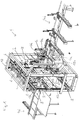
- Fig. 1 to 3 show an embodiment of a woodworking device 1 for the processing of wood elements with multiple units 2 and with a guide device which is able to bring the units 2 and a not shown to be processed wood element in a desired relative position.
- the guide device comprises two yz guides 3 for units 2 and an x-guide 4 for a wood element to be machined.
- Each unit 2 comprises a connecting device 5, which can be moved on a first rail 6 aligned in the y-direction.
- an upper and a lower first rail 6 are movable on two aligned in the z-direction second rails 7, wherein each two z-drives 6a are used for the exact positioning.
- the z-drives 6a are each attached to the first rails 6 and engage via gears in arranged along the second rails 7 racks. Wooden elements are positioned by the x-guide 4 perpendicular to the plane defined by the yz guides 3 level.
- the units 2 on the upper first rail 6 are arranged with downwardly projecting tool heads 8 and the units 2 on the lower first rail 6 with upwardly projecting tool heads 8, so that the processing of a wood element from below and above or from all sides possible is.
- five units 2 are arranged on the guide device, namely three on the upper first rail 6 and two on the lower first rail 6.
- the required for machining unit 2 is guided along the first rail 6 to be processed wood element, said not required but arranged on the same first rail 6 units 2 are moved away from the required unit 2 and the wood element away.
- the number of units 2 arranged on the respective first rail 6 depends on which machining operations are to be carried out or how many tools are to be able to be used quickly.
- the upper first rail 6 is formed for three units 2 slightly longer than the lower first rail 6 for two units. If each unit comprises at least two, but preferably four, change chuck 12, for example, four units 2 at least eight and at five units 2 at most twenty tools 11 are ready for use at any time.
- the x-guide 4 for a wood element to be machined comprises guide elements 4a and z-drives 4b, at least on both sides of the working area 9, which position the wood element via frictional driving rollers 4c which can be pressed against the wood element from two sides.
- Pressable guide elements 4a and possibly also driven driving rollers 4c are optionally also arranged above and in particular below the wooden element.
- a long support device 4d is formed on the supply side. So that the processed long wooden elements can be removed from the working area 9, a long support device 4d is also arranged on the exit side. Because the work area 9 is very narrow, even short wood elements can be processed. It is sufficient for the processing if the wood elements can be held and positioned on at least one side of the working area 9, ie on the feed side and / or on the exit side of the x-guide 4.
- the second rails 7 are formed as parts of a frame 10, wherein the frame 10 carrier has, which extend along the sides of a cuboid.
- the frame 10 is additionally stabilized by extending to the frame parts stabilizing elements 10a.
- a housing 10 b is rotatably and pivotally mounted on the frame 10.
- Fig. 3 are exemplified tools 11 in the form of a circular saw blade and planing in change chuck 12 of the tool heads 8 shown used and in Fig. 2 also milling tools.
- the unit 2 comprises a plate-shaped connecting device 5 to the guide device.
- the connecting device 5 has four guide elements 5a which cooperate with corresponding rail elements of the first rails 6.
- a y-drive 13 is attached to the connecting device 5, which engages via a gear 13a in a arranged along the first rail 6 racks 13b.
- a first rotary device 14 for rotational movements about a first axis of rotation 14 ' is arranged directly at the connecting device 5.
- the first rotating device 14 comprises a first pivot bearing 14a fastened to the connecting device 5, in which a first rotary element 14b is rotatably mounted.
- a first rotary drive 15 which can rotate the first rotary element 14b via a first orientation transmission, is arranged on the connecting device 5.
- the first alignment transmission is designed as a transmission, preferably as a worm gear.
- the screw not shown, arranged on the first rotary drive 15 and this acts with the arranged on the first rotary member 14b worm wheel 16 (see. Fig. 6 ) together.
- the first rotary element 14 b is fixedly connected to a central unit section 17.
- the middle unit section 17 is constructed of a plurality of elements and in this case comprises a disc-shaped end 18 of a receiving area 19 for cables.
- a cup-shaped closure 20 of the receiving area 19 is connected to the Connected connecting device 5, so that cables are guided by the connecting device 5 through the cup-shaped closure 20 in the receiving area 19 and taken in cup-shaped closure with sufficient length for rotational movements, to then be guided by the rotating disk-shaped closure 18 in the central unit section 17.
- the tool head 8 is arranged substantially in the region of the first axis of rotation 14 'and the exchangeable chuck 12 can be aligned against the first pivot bearing 14a.
- the central unit section 17 extends away from the first axis of rotation 14 'with a radial housing 17a and subsequently leads to the end of the unit 2 with the tool head 8 at a distance from the first axis of rotation 14' with a longitudinal housing 17b parallel to the first axis of rotation 14 '.
- a second rotating device 21 is arranged between the central unit section 17 and the tool head 8, which comprises a second pivot bearing 22 and a second rotary drive 23 arranged on the central unit section 17.
- the second rotary bearing 22 comprises an outer sleeve part 22a of the central aggregate section 17, on which an inner sleeve part 22b of the tool head 8 is mounted via ball bearings 22c.
- the inner sleeve part 22 b is fixedly connected to the head housing 8 a of the tool head 8.
- the second rotary drive 23 makes a Drehauscardien of the tool head 8 relative to the central unit section 17 about a first axis of rotation 14 'vertically aligned second axis of rotation 21' adjustable.
- the rotary drive 23 is connected via an associated second alignment transfer 24 with the second pivot bearing 22.
- the second rotary drive 23 is arranged in the half of the middle unit section 17 facing the first pivot bearing 14a, in particular in a region with the first axis of rotation 14 ', so that the torques necessary for the turning are as small as possible.
- the second alignment transfer extends from the second rotary drive 23 over more than half the length of the central unit section 17 to the second pivot bearing 22 area and is formed as a positive gear with five alignment gears 25, with a first alignment gear 25 on the shaft of the rotary drive 23 and a final alignment gear 25 is disposed on the inner sleeve portion 22b of the tool head 8.
- the interventions between the gears 25 are adjustable slip, preferably by a minimum matched conical configuration of the alignment gears 25, so that between each two fixed alignment gears 25 an alignment gear 25 can be brought with screws in the slip-free engagement position.
- a drive motor 26 for providing the rotary movement for working tools is arranged on the connecting device 5 and connected via a drive transmission with the change chucks 12 of the tool head 8.
- the drive transmission respectively comprises a first and second shaft section 27, 28 centered on the first and second rotational axis 14 ', 21'.
- the region of the second shaft section 28 facing away from the tool head 8 is a Gear with gears, preferably arranged with two intermeshing bevel gears 29a and 29b, wherein the second bevel gear 29b is seated on the second shaft portion 28.
- the first bevel gear 29a is seated on a shaft section perpendicular to the second shaft section 28. In a simple embodiment, this may be the first shaft section 27.
- the drive transmission comprises a radially to the first axis of rotation 14 'staggered, central shaft portion 29 with the bevel gear 29b.
- the rotary motion introduced via the second shaft section 28 is transmitted to the exchangeable chuck 12.
- a gear with bevel gears is used in the head housing 8a.
- a third bevel gear 29 c is mounted on the second shaft and engages in four fourth bevel gears 29 d, which are each attached to a change chucks 12.
- the tool head 8 can be rotated arbitrarily about the second axis of rotation and thereby resulting from the tool head 8 to be overcome inertial forces are very small due to the small size of the tool head 8.
- the small design of the tool head 8 also allows tools used to be held close to the second axis of rotation and their alignment movements for respective operations require only a small working space.
- the small extension of the tool head allows disc or cylindrical tools such as circular saw blades and planing tools to protrude beyond the tool head even with small radii over a large area of their circumference.
- circular saw blades can already achieve a large working depth with medium diameters, because they protrude far enough over the tool head.
- a central portion of the drive transmission with the central shaft portion 29 at a distance from the first axis of rotation 14 ' is arranged and extends parallel to this.
- the drive transmission from the first shaft portion 27 to the middle shaft portion 29 includes a radial to the first axis of rotation 14 'transmission means in the form of a transmission transmission with preferably four gears 30, each of which directly adjacent engage each other and a first gear 30 on the first shaft portion 27 and a last gear 30 is arranged on the central shaft portion 29.
- the radial transmission device prefferably be constructed with a shaft section, such a solution requiring somewhat more space due to the bevel gears required for the connections to the first and middle shaft sections 27, 29 in the direction of the first axis of rotation 14 '.
- a remote from the second shaft portion 28 free end face of the tool head 8 is at a distance of at least 50 cm to the central shaft portion 29, or to the longitudinal housing 17b, in which the central shaft portion 29 is received.
- first shaft portion 27 could directly connect the shaft of the drive motor 26, optionally via a gear with gears.
- the drive motor is disposed adjacent to the first shaft portion 27, the shaft of the drive motor 26 being parallel to the first shaft portion 27 and V-belt pulleys 31 associated with each other on both shafts. In order to be able to tension the V-belts on these V-belt pulleys 31, the drive motor 26 is fastened adjustably to the connecting device 5 perpendicular to the first axis of rotation 14 '.
Abstract
Die Holzbearbeitungsvorrichtung (1) umfasst mindestens ein Aggregat (2) und eine Führungsvorrichtung wobei ein Aggregat (2) eine Verbindungseinrichtung (5) zur Führungsvorrichtung, einen Werkzeugkopf (8) mit mindestens einem Wechselfutter (12) für Werkzeuge (11) oder Werkzeughalter, eine Antriebsvorrichtung zum Antreiben des mindestens einen Wechselfutters (12) und zwischen der Verbindungseinrichtung (5) und dem Werkzeugkopf (8) bei der Verbindungseinrichtung (5) eine erste und beim Werkzeugkopf (8) eine zweite Drehvorrichtung (14, 21) für Drehbewegungen um eine erste bzw. eine zweite Drehachse (14', 21') umfasst. Die Antriebsvorrichtung umfasst einen an der Verbindungseinrichtung (5) angeordneten Antriebsmotor (26) und eine Antriebsübertragung vom Antriebsmotor (23) zum mindestens einen Wechselfutter (12) des Werkzeugkopfs (8), wobei die Antriebsübertragung bei der ersten und der zweiten Drehvorrichtung (14, 21) jeweils einen auf der ersten bzw. zweiten Drehachse (14', 21') zentriert angeordneten ersten bzw. zweiten Wellenabschnitt (27, 28) und beim vom Werkzeugkopf (8) abgewandten Ende des zweiten Wellenabschnitts (28) ein Getriebe mit Zahnrädern, vorzugsweise mit zwei ineinandergreifenden Kegelrädern (29a, 29b), umfasst.The woodworking device (1) comprises at least one unit (2) and a guide device wherein an aggregate (2) has a connecting device (5) for guiding device, a tool head (8) with at least one exchangeable chuck (12) for tools (11) or tool holder Driving device for driving the at least one change-over chuck (12) and between the connecting device (5) and the tool head (8) in the connecting device (5) a first and the tool head (8) a second rotating device (14, 21) for rotational movements about a first or a second axis of rotation (14 ', 21'). The drive device comprises a drive motor (26) arranged on the connection device (5) and a drive transmission from the drive motor (23) to the at least one change chuck (12) of the tool head (8), wherein the drive transmission in the first and the second rotation device (14, 21 ) each one on the first and second axis of rotation (14 ', 21') centered arranged first and second shaft portion (27, 28) and the tool head (8) facing away from the second shaft portion (28) a gear with gears, preferably with two intermeshing bevel gears (29a, 29b).
Description
Die Erfindung bezieht sich auf Holzbearbeitungsvorrichtungen nach dem Oberbegriff des Anspruchs 1. Diese Holzbearbeitungsvorrichtungen werden für die mit verschiedenen Werkzeugen durchgeführte Bearbeitung von Holzelementen verwendet und sie umfassen mindestens ein Aggregat mit mindestens einem Wechselfutter für Werkzeuge oder Werkzeughalter. Es werden beispielsweise Werkzeuge zum Sägen, Bohren, Fräsen, Hobeln, Kehlen oder Nuten eingesetzt. Das Aggregat kann ein eingesetztes Werkzeug in eine für die Bearbeitung eines Holzelementes gewünschten Richtung ausrichten und zur Bearbeitung in Drehbewegung versetzten. Damit ein ausgerichtetes Werkzeug und eine zu bearbeitende Stelle eines Holzelementes miteinander in Kontakt gebracht werden können, umfasst die Holzbearbeitungsvorrichtung eine Führungsvorrichtung. Die Führungsvorrichtung umfasst eine Aggregatführung zum Bewegen des Aggregats und/oder eine Elementführung zum Bewegen des Holzelementes.The invention relates to woodworking devices according to the preamble of claim 1. These woodworking devices are used for the machining of wood elements performed with different tools and they comprise at least one aggregate with at least one change-over chuck for tools or tool holders. For example, tools are used for sawing, drilling, milling, planing, throats or grooves. The unit can align an inserted tool in a direction desired for the machining of a wooden element and set in rotation for machining. In order for an aligned tool and a workpiece of a wood element to be processed to be brought into contact with each other, the woodworking device comprises a guide device. The guide device comprises an assembly guide for moving the unit and / or an element guide for moving the wood element.
Die erfindungsgemässe Aufgabe besteht nun darin, eine einfach aufgebaute und effizient arbeitende Holzbearbeitungsvorrichtung zu finden.The object of the invention is now to find a simply constructed and efficiently working woodworking device.
Die Aufgabe wird durch die Merkmale des Patentanspruchs 1 gelöst. Die abhängigen Patentansprüche beschreiben alternative bzw. vorteilhafte Ausführungsvarianten, welche weitere Aufgaben lösen.The object is solved by the features of patent claim 1. The dependent claims describe alternative or advantageous embodiments, which solve other problems.
Eine erfindungsgemässe Holzbearbeitungsvorrichtung für die Bearbeitung von Holzelementen umfasst zumindest ein Aggregat und eine Führungsvorrichtung, wobei die Führungsvorrichtung das mindestens eine Aggregat und ein zu bearbeitendes Holzelement in eine gewünschte Relativlage zu bringen vermag. Das mindestens eine Aggregat umfasst eine Verbindungseinrichtung zur Führungsvorrichtung, beispielsweise eine in y- und z-Richtung verschiebbare Grundplatte, einen Werkzeugkopf mit mindestens einem Wechselfutter für Werkzeuge oder Werkzeughalter und zwischen der Verbindungseinrichtung und dem Werkzeugkopf bei der Verbindungseinrichtung eine erste und beim Werkzeugkopf eine zweite Drehvorrichtung für Drehbewegungen um eine erste bzw. eine zweite Drehachse, wobei die erste und die zweite Drehachse zueinander senkrecht ausgerichtet sind. Es versteht sich von selbst, dass das Aggregat auch Aggregatteile bzw. Gehäuseteile umfasst, an denen Elemente des Aggregats angeordnet sind.An inventive woodworking device for processing wooden elements comprises at least one unit and a guide device, wherein the guide device is capable of bringing the at least one unit and a wood element to be processed into a desired relative position. The at least one unit comprises a connecting device to the guide device, for example a displaceable in the y- and z-direction base plate, a tool head with at least one change chuck for tools or tool holder and between the connecting device and the tool head in the connecting device a first and the tool head a second rotating device for rotational movements about a first or a second axis of rotation, wherein the first and the second axis of rotation are aligned perpendicular to each other. It goes without saying that the unit also comprises unit parts or housing parts on which elements of the unit are arranged.
In einem erfinderischen Schritt wurde erkannt, dass es vorteilhaft ist, wenn der Antriebsmotor zum Bereitstellen der Drehbewegung für arbeitende Werkzeuge nicht direkt beim Wechselfutter für die Werkzeuge oder Werkzeughalter angeordnet wird, sondern bei der Verbindungseinrichtung. Dadurch wird es zwar notwendig, dass die Antriebsvorrichtung zum Antreiben des mindestens einen Wechselfutters nebst dem Antriebsmotor, zusätzlich eine Antriebsübertragung vom Antriebsmotor zum mindestens einen Wechselfutter des Werkzeugkopfs umfasst. Damit dies nicht zu Nachteilen sondern zu Vorteilen führt, umfasst die Antriebsübertragung bei der ersten und der zweiten Drehvorrichtung jeweils einen auf der ersten bzw. zweiten Drehachse zentriert angeordneten ersten bzw. zweiten Wellenabschnitt und beim vom Werkzeugkopf abgewandten Bereich des zweiten Wellenabschnitts ein formschlüssiges Getriebe mit Zahnrädern, vorzugsweise mit zwei ineinandergreifenden Kegelrädern.In an inventive step, it has been recognized that it is advantageous if the drive motor for providing the rotary movement for working tools is not arranged directly at the exchangeable chuck for the tools or tool holders, but at the connecting device. As a result, it becomes necessary for the drive device for driving the at least one change-over chuck, in addition to the drive motor, to additionally comprise a drive transmission from the drive motor to the at least one change chuck of the tool head. So that this does not lead to disadvantages but to advantages, the drive transmission in the first and the second rotating device each comprises a centered on the first and second axis of rotation arranged first and second shaft portion and the tool head remote from the second shaft portion a positive gear with gears , preferably with two intermeshing bevel gears.
Mit dieser Antriebsübertragung kann der Werkzeugkopf äusserst klein gebaut werden. In der einfachsten Ausführung der Antriebsübertragung ist der erste Wellenabschnitt über zwei Kegelräder mit dem zweiten Wellenabschnitt verbunden. Bei bevorzugten weiteren Ausführungsformen ist zwischen dem ersten und dem zweiten Wellenabschnitt ein formschlüssiges Getriebe mit weiteren Zahnrädern und gegebenenfalls mindestens einem weiterer Wellenabschnitt eingesetzt. Die Antriebsübertragung über Getriebe mit Zahnrädern und Wellen kann kompakt gebaut werden und sie ist mit einem minimalen Wartungsaufwand verbunden. Die Geometrie bzw. die Relativlage zwischen dem ersten und dem zweiten Wellenabschnitt bzw. zwischen der Verbindungseinrichtung und dem Werkzeugkopf bleibt immer gleich, was mit kleinem Aufwand eine hohe Präzision bei der Bearbeitung von Holzteilen gewährleistet. Wenn die Führungseinrichtung die Verbindungseinrichtung relativ zum Holzelement positioniert hat, so ist die Lage des Werkzeugkopfs genau bestimmt.With this drive transmission, the tool head can be built extremely small. In the simplest embodiment of the drive transmission of the first shaft portion is connected via two bevel gears with the second shaft portion. In preferred further embodiments, between the first and the second shaft portion a positive gear with other gears and possibly at least one further shaft portion is used. The drive transmission via gears with gears and shafts can be made compact and it is associated with a minimum of maintenance. The geometry or the relative position between the first and the second shaft section or between the connecting device and the tool head always remains the same, which ensures high precision in the processing of wood parts with little effort. If the guide device has positioned the connection device relative to the wood element, then the position of the tool head is precisely determined.
Im Werkzeugkopf muss lediglich die über den zweiten Wellenabschnitt eingebrachte Drehbewegung auf mindestens ein Wechselfutter übertragen werden. Vorzugsweise erfolgt diese Übertragung auf eine quer, insbesondere aber senkrecht, zum zweiten Wellenabschnitt ausgerichtete Verbindungswelle zum mindestens einen Wechselfutter, was beispielsweise mit einem Kegelradgetriebe erzielt werden kann. Weil keine elektrischen Leitungen in den Werkzeugkopf bzw. zum Bereich mit dem mindestens einen Wechselfutter geführt werden müssen, können beliebige Drehbewegungen um die erste und die zweite Drehachse ausgeführt werden. Der Werkzeugkopf mit dem mindestens einen Wechselfutter ist am Aggregat uneingeschränkt bewegbar.In the tool head, only the rotary motion introduced via the second shaft section has to be transferred to at least one replacement chuck. Preferably, this transmission takes place on a transverse, but in particular perpendicular, aligned to the second shaft portion connecting shaft to at least one change chuck, which can be achieved for example with a bevel gear. Because no electrical lines in the tool head or to the area with the at least a change chuck must be performed, any rotational movements about the first and the second axis of rotation can be performed. The tool head with the at least one change chuck is fully movable on the unit.
Weil der Werkzeugkopf ohne Antriebsmotor sehr klein ausgebildet werden kann, sind die bei Drehungen zu überwindenden Trägheitskräfte sehr klein, was die Beweglichkeit erhöht. Die kleine Bauweise des Werkzeugkopfs ermöglicht auch, dass die Werkzeuge nahe bei der zweiten Drehachse gehalten sind und ihre Ausrichtungs-Bewegungen für jeweilige Bearbeitungen nur einen kleinen Arbeitsraum beanspruchen. Zudem ermöglicht die kleine Ausdehnung des Werkzeugkopfs, dass scheiben- oder zylinderförmige Werkzeuge wie Kreissägeblätter und Hobel-Werkzeuge bereits mit kleinen Radien in einem grossen Bereich Ihres Umfangs über den Werkzeugkopf bzw. über das Aggregat vorstehen. Kreissägeblätter können bereits mit mittleren Durchmessern eine grosse Arbeitstiefe erzielen, weil sie genügend weit über den Werkzeugkopf vorstehen.Because the tool head without a drive motor can be made very small, the inertial forces to be overcome during rotations are very small, which increases the mobility. The small design of the tool head also allows the tools to be held close to the second axis of rotation and their alignment movements require only a small working space for respective machining operations. In addition, the small extension of the tool head allows disk-shaped or cylindrical tools such as circular saw blades and planing tools to protrude over the tool head or over the unit even with small radii over a large area of their circumference. Circular saw blades can achieve a large working depth even with medium diameters, because they protrude far enough over the tool head.
Weil im Werkzeugkopf lediglich die Bewegung vom zweiten Wellenabschnitt in dazu quer verlaufende Richtungen übertragen wird, ist es auf kleinstem Raum möglich, mehrere vom zweiten Wellenabschnitt wegführende Wechselfutter anzuordnen. Die Wechselfutter werden vom zweiten Wellenabschnitt über Getriebe angetrieben, wobei die Getriebe vorzugsweise als Kegelradgetriebe ausgebildet sind. Besonders vorteilhaft sind Ausführungen, bei denen in gleichmässigen Umfangsabständen um den zweiten Wellenabschnitt Wechselfutter angeordnet sind, deren Achsen sich senkrecht zum zweiten Wellenabschnitt erstrecken, wobei mindestens zwei, vorzugsweise vier und gegebenenfalls sechs Wechselfutter angeordnet sind. Vorzugsweise wird der Werkzeugkopf quaderförmig, insbesondere im Wesentlichen würfelförmig ausgebildet und umfasst in vier Aussenflächen je ein Wechselfutter. Es wäre aber auch mögliche in sechs gleichmässig um den zweiten Wellenabschnitt verteilten Richtungen je ein Wechselfutter anzuordnen. Selbst ein Wechselfutter in der Verlängerung des zweiten Wellenabschnitts ist möglich. Bei einer Mehrzahl von Wechselfuttern ist immer eine entsprechende Anzahl von Werkzeugen einsatzbereit. Darum kann mit einem erfindungsgemässen Aggregat in vielen Anwendungen auf eine automatische Wechselvorrichtung für Werkzeuge verzichtet werden.Because only the movement of the second shaft portion in the transverse direction is transmitted to the tool head, it is possible in a small space to arrange a plurality of alternating chuck leading away from the second shaft portion. The change chucks are driven by the second shaft portion via gear, the gears are preferably designed as bevel gear. Particularly advantageous embodiments are those in which are arranged at uniform circumferential intervals about the second shaft portion change chuck whose axes extend perpendicular to the second shaft portion, wherein at least two, preferably four and optionally six interchangeable chucks are arranged. Preferably, the tool head is parallelepiped-shaped, in particular essentially cube-shaped, and in each case comprises an exchangeable chuck in four outer surfaces. However, it would also be possible to arrange an exchange chuck in six directions uniformly distributed around the second shaft section. Even an exchangeable chuck in the extension of the second shaft section is possible. In a plurality of change chucks always a corresponding number of tools is ready for use. For this reason, with an assembly according to the invention, an automatic changing device for tools can be dispensed with in many applications.
Bei einer bevorzugten Ausführungsform ist zwischen den beiden Drehvorrichtungen ein mittlerer Abschnitt der Antriebsübertragung in einem Abstand zur ersten Drehachse angeordnet und verläuft vorzugsweise parallel zu dieser. Die Antriebsübertragung vom ersten Wellenabschnitt zum mittleren Abschnitt der Antriebsübertragung umfasst eine zur ersten Drehachse radiale Übertragungseinrichtung und das von der radialen Übertragungseinrichtung abgewandte Ende des mittlerer Abschnitts der Antriebsübertragung steht in Antriebsverbindung zum zweiten Wellenabschnitt.In a preferred embodiment, a middle section of the drive transmission is at a distance from the first axis of rotation between the two rotary devices arranged and preferably runs parallel to this. The drive transmission from the first shaft portion to the middle portion of the drive transmission comprises a transmission means radial to the first axis of rotation and the remote from the radial transmission end of the central portion of the drive transmission is in driving connection with the second shaft portion.
Bei einer solchen Ausführungsform kann das Aggregat so ausgebildet werden, dass der Werkzeugkopf und damit das mindestens eine Wechselfutter im Bereich der ersten Drehachse liegt und sich die Werkzeuge bei um die zweite Achse drehendem Werkzeugkopf nur innerhalb eines minimalen Bereichs bewegen. Entsprechend klein sind der benötigte Arbeitsbereich und die darin anzuordnenden Sammel- und Abführvorrichtungen für vom Holzelement abgetrennte Teile.In such an embodiment, the unit may be formed so that the tool head and thus the at least one change chuck lies in the region of the first axis of rotation and the tools move only within a minimum range with tool head rotating about the second axis. Correspondingly small are the required working area and the collection and discharge devices to be arranged for parts separated from the wood element.
In einer weiter bevorzugten Ausführungsform umfasst die radiale Übertragungseinrichtung eine Getriebe-Übertragung mit in Serie angeordneten Zahnrädern, von denen jeweils direkt benachbarte ineinander eingreifen, mit mindestens zwei vorzugsweise aber mit vier Zahnrädern. Es ist auch möglich, dass die radiale Übertragungseinrichtung einen Wellenabschnitt umfasst. Die gewählte radiale Übertragungseinrichtung ist über passende Zahnräder, insbesondere Kegelräder, einerseits mit dem ersten Wellenabschnitt und andererseits mit dem mittleren Abschnitt der Antriebsübertragung verbunden.In a further preferred embodiment, the radial transmission device comprises a transmission transmission with gears arranged in series, of which directly adjacent intermesh with each other, with at least two but preferably with four gears. It is also possible that the radial transmission device comprises a shaft section. The selected radial transmission device is connected via suitable gears, in particular bevel gears, on the one hand with the first shaft portion and on the other hand with the central portion of the drive transmission.
Der mittlere Abschnitt der Antriebsübertragung kann einen mittleren Wellenabschnitt oder insbesondere eine Getriebe-Übertragung mit in Serie angeordneten Zahnrädern, von denen jeweils direkt benachbarte ineinander eingreifen, umfassen, wobei ein mittlerer Wellenabschnitt aufgrund der benötigten Länge bevorzugt ist.The middle portion of the drive transmission may comprise a central shaft portion or, in particular, a transmission transmission with serially arranged gears, each of which directly adjacent engage each other, wherein a central shaft portion is preferred due to the required length.
In einer weiteren bevorzugten Ausführungsform liegt eine vom zweiten Wellenabschnitt abgewandte freie Stirnfläche des Werkzeugkopfs in einem Abstand von mindestens 50 cm zum mittleren Abschnitt der Antriebsübertragung. Dadurch kann im Bereich eines in den Werkzeugkopf eingesetzten Werkzeugs rund um das mindestens eine Wechselfutter ein grosser Abstand zu den Teilen des Aggregats bereitgestellt werden. Entsprechend können alle Werkzeuge, die sich radial weniger weit ausdehnen als dieser Abstand, am Werkzeugkopf rund um die zweite Drehachse gedreht werden.In a further preferred embodiment, a free end face of the tool head remote from the second shaft section lies at a distance of at least 50 cm from the middle section of the drive transmission. As a result, in the region of a tool inserted into the tool head, a large distance to the parts of the assembly can be provided around the at least one change-over chuck. Accordingly, all tools that expand radially less than this distance can be rotated on the tool head around the second axis of rotation.
Es ist vorteilhaft, wenn der Bereich des zweiten Wellenabschnitts, in dem die Wechselfutter um diesen angeordnet sind, bei der ersten Drehachse angeordnet ist, weil sich dadurch die Werkzeuge aller Wechselfutter lediglich innerhalb eines minimalen Bereichs bewegen.It is advantageous if the region of the second shaft section in which the interchangeable chucks are arranged around the latter is arranged at the first axis of rotation, because thereby the tools of all interchangeable chucks only move within a minimal range.
Ein vorteilhaftes Aggregat erzielt die Drehungen des Werkzeugkopfs um zwei zueinander senkrechte Achsen mit zwei Drehvorrichtungen. Die erste Drehvorrichtung umfasst eine zwischen dem Verbindungsteil und einem mittleren Aggregatabschnitt angeordnete erste Drehlagerung und einen am Verbindungsteil angeordneten ersten Drehantrieb. Die zweite Drehvorrichtung umfasst eine zwischen dem mittleren Aggregatabschnitt und dem Werkzeugkopf angeordnete zweite Drehlagerung und einen am mittleren Aggregatabschnitt angeordneten zweiten Drehantrieb. Der erste und der zweite Drehantrieb machen je über diesen zugeordnete erste bzw. zweite Ausrichtungsübertragungen die gewünschten relativen Ausrichtungen der beidseits der jeweiligen Drehlagerungen angeordneten Teile einstellbar. Durch die Verwendung von Servomotoren können die Drehausrichtungen nummerisch kontrolliert werden (NC-Achsen).An advantageous unit achieves the rotations of the tool head about two mutually perpendicular axes with two rotating devices. The first rotating device comprises a first rotary bearing arranged between the connecting part and a central unit section and a first rotary drive arranged on the connecting part. The second rotary device comprises a second rotary bearing arranged between the central unit section and the tool head and a second rotary drive arranged on the central unit section. The first and the second rotary drive each make the desired relative orientations of the parts arranged on both sides of the respective rotary mountings adjustable by way of these associated first and second alignment transmissions. By using servomotors, the rotational orientations can be numerically controlled (NC axes).
In einer bevorzugten Ausführungsform ist die erste Ausrichtungsübertragung als Getriebe, insbesondere als Schneckengetriebe ausgebildet, wobei die Schnecke am ersten Drehantrieb angeordnet ist und das Schneckenrad am ersten Wellenabschnitt. Damit kann immer eine präzise Drehausrichtung gewährleistet werden.In a preferred embodiment, the first alignment transmission is designed as a gear, in particular as a worm gear, wherein the worm is arranged on the first rotary drive and the worm wheel on the first shaft section. This can always be guaranteed a precise Drehausrichtung.
In einer bevorzugten Ausführungsform ist der zweite Drehantrieb in der der ersten Drehlagerung zugewandten Hälfte des mittleren Aggregatabschnitts angeordnet, vorzugsweise in einem Bereich mit der ersten Drehachse, so dass die für das Drehen nötigen Drehmomente möglichst klein sind. Die zweite Ausrichtungsübertragung erstreckt sich vom zweiten Drehantrieb über mindestens die halbe Länge des mittleren Aggregatabschnitts bis zum Bereich mit der zweiten Drehlagerung und ist vorzugsweise als Getriebe, insbesondere mit mindestens drei, vorzugsweise aber mit fünf Zahnrädern ausgebildet. Um immer eine präzise Drehausrichtung zu gewährleisten sind die Eingriffe zwischen den Zahnrädern schlupffrei einstellbar. Gegebenenfalls umfasst die zweite Ausrichtungsübertragung mindestens eine Welle und mindestens ein Kegelradgetriebe.In a preferred embodiment, the second rotary drive is arranged in the half of the middle unit section facing the first pivot bearing, preferably in a region with the first axis of rotation, so that the torques required for turning are as small as possible. The second alignment transmission extends from the second rotary drive over at least half the length of the central unit section to the area with the second pivot bearing and is preferably designed as a transmission, in particular with at least three, but preferably with five gears. In order to always ensure a precise Drehausrichtung the interventions between the gears are slip-free adjustable. Optionally, the second alignment transmission comprises at least one shaft and at least one bevel gear.
Der Abstand zwischen dem zweiten Drehantrieb und dem Werkzeugkopf schliesst störende Wirkungen des Werkzeugkopfs auf Sensorelemente und Elektronikelemente des vorzugsweise als Servomotor ausgebildeten zweiten Drehantriebs im Wesentlichen aus. Das heisst beispielsweise, dass sich die beim Werkzeugkopf aufgrund des Getriebes entstehende Wärme nicht störend auf die Einsatzbereitschaft und den nötigen Unterhalt des zweiten Drehantriebs auswirkt.The distance between the second rotary drive and the tool head essentially eliminates interfering effects of the tool head on sensor elements and electronic elements of the second rotary drive, which is preferably designed as a servomotor. This means, for example, that the heat generated in the tool head due to the transmission does not interfere with the operational readiness and the necessary maintenance of the second rotary drive.
In einer bevorzugten Ausführungsform ergibt sich zwischen dem zweiten Drehantrieb und dem Werkzeugkopf bei einem zur ersten Drehachse seitlich versetzten mittleren Abschnitt der Antriebsübertragung im Bereich der ersten Drehachse ein Freiraum. Dieser Freiraum wird in der Richtung der ersten Drehachse und von dieser zum mittleren Aggregatabschnitt so dimensioniert, dass zumindest ein Teil der gängigen Werkzeuge eingesetzt in einem Wechselfutter mit dem Werkzeugkopf rund um die zweite Drehachse drehbar sind.In a preferred embodiment, a free space is created between the second rotary drive and the tool head in the middle section of the drive transmission laterally offset relative to the first axis of rotation in the region of the first axis of rotation. This clearance is dimensioned in the direction of the first axis of rotation and from this to the central unit section so that at least a part of the common tools used in an exchange chuck with the tool head are rotatable about the second axis of rotation.
Die beschriebenen Aggregate können in Verbindung mit bekannten Führungsvorrichtungen eingesetzt werden und dabei entstehen erfindungsgemässe Holzbearbeitungsvorrichtungen.The aggregates described can be used in conjunction with known guide devices and thereby arise inventive woodworking devices.
Bei einer bevorzugten Ausführungsform umfasst die Führungsvorrichtung mindestens eine y-z-Führung für mindestens eine Verbindungseinrichtung und eine x-Führung für ein zu bearbeitendes Holzelement. Die mindestens eine Verbindungseinrichtung ist an einer in y-Richtung ausgerichteten ersten Schiene der mindestens einen y-z-Führung verfahrbar. Die erste Schiene ist an zwei in z-Richtung ausgerichteten zweiten Schienen verfahrbar. Die erste Drehachse des mindestens einen Aggregates ist in z-Richtung ausgerichtet und das Holzelement ist von der x-Führung senkrecht zu der von der y-z-Führung festgelegten Ebene positionierbar.In a preferred embodiment, the guide device comprises at least one y-z guide for at least one connecting device and an x-guide for a wood element to be machined. The at least one connecting device can be moved on a first rail of the at least one y-z guide aligned in the y direction. The first rail is movable on two aligned in the z-direction second rails. The first axis of rotation of the at least one aggregate is aligned in the z-direction and the wooden element is positionable by the x-guide perpendicular to the plane defined by the y-z-guide.
Besonders vielfältig einsetzbar ist eine Holzbearbeitungsvorrichtung, bei welcher die Führungsvorrichtung zwei y-z-Führungen umfasst, von denen die in y-Richtung ausgerichteten ersten Schienen vertikal versetzt an den gemeinsamen zweiten Schienen angeordnet sind, so dass an einer oberen und einer unteren ersten Schiene je mindestens eine Verbindungseinrichtung und mit dieser jeweils ein Aggregat verfahrbar ist. Die Aggregate an der oberen ersten Schiene sind mit nach unten vorstehenden Werkzeugköpfen und die Aggregate an der unteren ersten Schiene mit nach oben vorstehenden Werkzeugköpfen angeordnet. Dadurch wird eine vielfältige Bearbeitung des Holzelementes von unten und oben bzw. von allen Seiten möglich.Particularly versatile is a woodworking device, wherein the guide device comprises two yz guides, of which the first rails aligned in the y direction are arranged vertically offset on the common second rails, so that at least one upper and one lower first rail Connecting device and with this one unit is movable. The aggregates on the upper first rail are arranged with downwardly projecting tool heads and the aggregates on the lower first rail with upwardly projecting tool heads. This will a versatile processing of the wood element from below and above or from all sides possible.
Bei einer bevorzugten Ausführungsform sind mindestens vier vorzugsweise mindestens fünf Aggregate an der Führungsvorrichtung angeordnet, wobei jedes Aggregat mindestens zwei, vorzugsweise vier Wechselfutter umfasst, so dass jederzeit mindestens acht, vorzugsweise aber zwanzig Werkzeuge einsatzbereit sind.In a preferred embodiment, at least four preferably at least five units are arranged on the guide device, wherein each unit comprises at least two, preferably four exchangeable chuck, so that at least eight, but preferably twenty tools are ready for use at any time.
Die Zeichnungen erläutern die Erfindung anhand eines Ausführungsbeispiels, auf das sie aber nicht eingeschränkt ist. Dabei zeigen
- Fig. 1
- eine perspektivische Darstellung einer Holzbearbeitungsvorrichtung,
- Fig. 2
- eine Seitenansicht des Bearbeitungsbereichs der Holzbearbeitungsvorrichtung der
Fig. 1 , - Fig. 3
- eine Ansicht auf die Rückseite des Bearbeitungsbereichs der Holzbearbeitungs-vorrichtung der
Fig. 1 , - Fig. 4
- eine Seitenansicht eines Aggregats,
- Fig. 5
- eine Ansicht auf die Rückseite des Aggregats der
Fig. 4 , und - Fig. 6
- einen Schnitt durch das Aggregat in der Ausrichtung gemäss
Fig. 5 .
- Fig. 1
- a perspective view of a woodworking device,
- Fig. 2
- a side view of the processing area of the woodworking device of
Fig. 1 . - Fig. 3
- a view of the back of the processing area of the woodworking device of
Fig. 1 . - Fig. 4
- a side view of an aggregate,
- Fig. 5
- a view on the back of the unit of the
Fig. 4 , and - Fig. 6
- a section through the unit in the orientation according to
Fig. 5 ,
Die Aggregate 2 an der oberen ersten Schiene 6 sind mit nach unten vorstehenden Werkzeugköpfen 8 und die Aggregate 2 an der unteren ersten Schiene 6 mit nach oben vorstehenden Werkzeugköpfen 8 angeordnet, so dass die Bearbeitung eines Holzelementes von unten und oben bzw. von allen Seiten möglich ist. Bei der dargestellten Ausführungsform sind fünf Aggregate 2 an der Führungsvorrichtung angeordnet, nämlich drei an der oberen ersten Schiene 6 und zwei an der unteren ersten Schiene 6. Das für eine Bearbeitung benötigte Aggregat 2 wird entlang der ersten Schiene 6 zum zu bearbeitenden Holzelement geführt, wobei nicht benötigte aber an der gleichen ersten Schiene 6 angeordnete Aggregate 2 vom benötigten Aggregat 2 und vom Holzelement weg bewegt werden. Die Anzahl der an der jeweiligen ersten Schiene 6 angeordneten Aggregate 2 hängt davon ab, welche Bearbeitungen durchgeführt werden sollen bzw. wie viele Werkzeuge schnell einsetzbar sein sollen. Damit für die nicht benötigten Aggregate 2 genügend Platz vorhanden ist, ist die obere erste Schiene 6 für drei Aggregate 2 etwas länger ausgebildet als die untere erste Schiene 6 für zwei Aggregate. Wenn jedes Aggregat mindestens zwei, vorzugsweise aber vier, Wechselfutter 12 umfasst, so sind bei beispielsweise vier Aggregaten 2 jederzeit mindestens acht und bei fünf Aggregaten 2 maximal zwanzig Werkzeuge 11 einsatzbereit.The
Die x-Führung 4 für ein zu bearbeitendes Holzelement umfasst zumindest auf beiden Seiten des Arbeitsbereichs 9 Führungselemente 4a und z-Antriebe 4b, welche über reibungsschlüssige von zwei Seiten an das Holzelement anpressbare Mitnahmewalzen 4c das Holzelement positionieren. Anpressbare Führungselemente 4a und gegebenenfalls auch angetriebene Mitnahmewalzen 4c sind gegebenenfalls auch über und insbesondere unter dem Holzelement angeordnet. Um lange Holzelemente zuführen zu können, ist auf der Zuführseite eine lange Auflagevorrichtung 4d ausgebildet. Damit die bearbeiteten langen Holzelemente aus dem Arbeitsbereich 9 entnommen werden können, ist auf der Austrittsseite ebenfalls eine lange Auflagevorrichtung 4d angeordnet. Weil der Arbeitsbereich 9 sehr schmal ist, können auch kurze Holzelemente bearbeitet werden. Es genügt für die Bearbeitung, wenn die Holzelemente auf zumindest einer Seite des Arbeitsbereichs 9, also auf der Zuführseite und/oder auf der Austrittsseite von der x-Führung 4 gehalten und positioniert werden kann.The x-guide 4 for a wood element to be machined comprises
Damit die Holzbearbeitungsvorrichtung 1 eine hohe Stabilität erhält, sind die zweiten Schienen 7 als Teile eines Rahmens 10 ausgebildet, wobei der Rahmen 10 Träger aufweist, die sich entlang der Seiten eines Quaders erstrecken. Der Rahmen 10 wird durch schief zu den Rahmenteilen verlaufende Stabilisierungselemente 10a zusätzlich stabilisiert. Für die Aufnahme einer Bedienung der Holzbearbeitungsvorrichtung 1 ist ein Gehäuse 10b dreh- und schwenkbar am Rahmen 10 angeordnet.In order that the woodworking device 1 obtains a high stability, the second rails 7 are formed as parts of a
In
An dem von der Verbindungseinrichtung 5 abgelegenen Ende des Aggregats 2 ist der Werkzeugkopf 8 mit vier Wechselfuttern 12 für Werkzeuge oder Werkzeughalter angeordnet. Zwischen der Verbindungseinrichtung 5 und dem Werkzeugkopf 8 ist direkt bei der Verbindungseinrichtung 5 eine erste Drehvorrichtung 14 für Drehbewegungen um eine erste Drehachse 14' angeordnet. Die erste Drehvorrichtung 14 umfasst eine an der Verbindungseinrichtung 5 befestigte erste Drehlagerung 14a, in welcher ein erstes Drehelement 14b drehbar gelagert ist. Um das erste Drehelement 14b in einer exakten Drehausrichtung positionieren zu können, ist an der Verbindungseinrichtung 5 ein erster Drehantrieb 15 angeordnet, der über eine erste Ausrichtungsübertragung das erste Drehelement 14b drehen kann. Die erste Ausrichtungsübertragung ist als Getriebe, vorzugsweise als Schneckengetriebe ausgebildet. Dabei ist die nicht dargestellte Schnecke am ersten Drehantrieb 15 angeordnet und diese wirkt mit dem am ersten Drehelement 14b angeordneten Schneckenrad 16 (vgl.
Das erste Drehelement 14b ist fest mit einem mittleren Aggregatabschnitt 17 verbunden. Der mittlere Aggregatabschnitt 17 ist aus mehreren Elementen aufgebaut und umfasst dabei einen scheibenförmigen Abschluss 18 eines Aufnahmebereiches 19 für Kabel. Ein topfförmiger Abschluss 20 des Aufnahmebereiches 19 ist mit der Verbindungseinrichtung 5 verbunden, so dass Kabel von der Verbindungseinrichtung 5 durch den topfförmigen Abschluss 20 in den Aufnahmebereich 19 geführt und im topfförmigen Abschluss mit genügender Länge für Drehbewegungen aufgenommen werden, um anschliessend durch den drehenden scheibenförmigen Abschluss 18 in den mittleren Aggregatabschnitt 17 geführt zu werden.The first rotary element 14 b is fixedly connected to a
In der dargestellten Ausführungsform ist der Werkzeugkopf 8 im Wesentlichen im Bereich der ersten Drehachse 14' angeordnet und die Wechselfutter 12 können gegen die erste Drehlagerung 14a ausgerichtet werden. Entsprechend erstreckt sich der mittlere Aggregatabschnitt 17 mit einem Radialgehäuse 17a von der ersten Drehachse 14' weg und führt anschliessend in einem Abstand zur ersten Drehachse 14' mit einem Längsgehäuse 17b parallel zur ersten Drehachse 14' gegen das Ende des Aggregats 2 mit dem Werkzeugkopf 8.In the illustrated embodiment, the
Am Längsgehäuse 17b ist eine zweite Drehvorrichtung 21 zwischen dem mittleren Aggregatabschnitt 17 und dem Werkzeugkopf 8 angeordnet, welche eine zweite Drehlagerung 22 und einen am mittleren Aggregatabschnitt 17 angeordneten zweiten Drehantrieb 23 umfasst. Die zweite Drehlagerung 22 umfasst einen äusseren Hülsenteil 22a des mittleren Aggregatabschnitts 17, an dem über Kugellager 22c ein innerer Hülsenteil 22b des Werkzeugkopfs 8 gelagert ist. Der innere Hülsenteil 22b ist fest mit dem Kopfgehäuse 8a des Werkzeugkopfs 8 verbunden. Der zweite Drehantrieb 23 macht eine Drehausrichtungen des Werkzeugkopfs 8 relativ zum mittleren Aggregatabschnitt 17 um eine zur ersten Drehachse 14' senkrecht ausgerichtete zweite Drehachse 21' einstellbar. Der Drehantrieb 23 ist dabei über eine zugeordnete zweite Ausrichtungsübertragung 24 mit der zweiten Drehlagerung 22 verbunden.On the longitudinal housing 17b, a second
Der zweite Drehantrieb 23 ist in der der ersten Drehlagerung 14a zugewandten Hälfte des mittleren Aggregatabschnitts 17 angeordnet, insbesondere in einem Bereich mit der ersten Drehachse 14', so dass die für das Drehen nötigen Drehmomente möglichst klein sind. Die zweite Ausrichtungsübertragung erstreckt sich vom zweiten Drehantrieb 23 über mehr als die halbe Länge des mittleren Aggregatabschnitts 17 bis zum Bereich mit der zweiten Drehlagerung 22 und ist als formschlüssiges Getriebe mit fünf Ausrichtungszahnrädern 25 ausgebildet, wobei ein erstes Ausrichtungszahnrad 25 auf der Welle des Drehantriebs 23 und ein letztes Ausrichtungszahnrad 25 am innerer Hülsenteil 22b des Werkzeugkopfs 8 angeordnet ist. Um immer eine präzise Drehausrichtung zu gewährleisten sind die Eingriffe zwischen den Zahnrädern 25 schlupffrei einstellbar, vorzugsweise durch eine minimale aneinander angepasste konische Ausgestaltung der Ausrichtungszahnräder 25, so dass jeweils zwischen zwei fix montierten Ausrichtungszahnräder 25 ein Ausrichtungszahnrad 25 mit Stellschrauben in die schlupffreie Eingriffslage gebracht werden kann.The
Ein Antriebsmotor 26 zum Bereitstellen der Drehbewegung für arbeitende Werkzeuge ist an der Verbindungseinrichtung 5 angeordnet und über eine Antriebsübertragung mit den Wechselfuttern 12 des Werkzeugkopfs 8 verbunden. Die Antriebsübertragung umfasst bei der ersten und der zweiten Drehvorrichtung 14, 21 jeweils einen auf der ersten bzw. zweiten Drehachse 14', 21' zentriert angeordneten ersten bzw. zweiten Wellenabschnitt 27, 28. Im vom Werkzeugkopf 8 abgewandten Bereich des zweiten Wellenabschnitts 28 ist ein Getriebe mit Zahnrädern, vorzugsweise mit zwei ineinandergreifenden Kegelrädern 29a und 29b angeordnet, wobei das zweite Kegelrad 29b auf dem zweiten Wellenabschnitt 28 sitzt. Das erste Kegelrad 29a sitzt auf einem zum zweiten Wellenabschnitt 28 senkrecht stehenden Wellenabschnitt. Bei einer einfachen Ausführungsform kann dies der erste Wellenabschnitt 27 sein. In der dargestellten Ausführungsform umfasst die Antriebsübertragung einen radial zur ersten Drehachse 14' versetzt angeordneten, mittleren Wellenabschnitt 29 mit dem Kegelrad 29b.A
Im Werkzeugkopf 8 wird die über den zweiten Wellenabschnitt 28 eingebrachte Drehbewegung auf die Wechselfutter 12 übertragen. Dazu ist im Kopfgehäuse 8a ein Getriebe mit Kegelrädern eingesetzt. Ein drittes Kegelrad 29c ist auf der zweiten Welle befestigt und greift in vier vierte Kegelräder 29d ein, welche je an einem Wechselfuttern 12 befestigt sind. Mit dieser Antriebsübertragung kann der Werkzeugkopf 8 beliebig um die zweite Drehachse gedreht werden und die dabei vom Werkzeugkopf 8 herrührenden zu überwindenden Trägheitskräfte sind aufgrund der kleinen Bauweise des Werkzeugkopfs 8 sehr klein. Die kleine Bauweise des Werkzeugkopfs 8 ermöglicht auch, dass eingesetzte Werkzeuge nahe bei der zweiten Drehachse gehalten sind und ihre Ausrichtungs-Bewegungen für jeweilige Bearbeitungen nur einen kleinen Arbeitsraum beanspruchen. Zudem ermöglicht die kleine Ausdehnung des Werkzeugkopfs, dass scheiben- oder zylinderförmige Werkzeuge wie Kreissägeblätter und Hobel-Werkzeuge bereits mit kleinen Radien in einem grossen Bereich Ihres Umfangs über den Werkzeugkopf vorstehen. Kreissägeblätter können bereits mit mittleren Durchmessern eine grosse Arbeitstiefe erzielen, weil sie genügend weit über den Werkzeugkopf vorstehen.In the
Bei der dargestellten Ausführungsform ist zwischen den beiden Drehvorrichtungen 14, 21 ein mittlerer Abschnitt der Antriebsübertragung mit dem mittleren Wellenabschnitt 29 in einem Abstand zur ersten Drehachse 14' angeordnet und verläuft parallel zu dieser. Die Antriebsübertragung vom ersten Wellenabschnitt 27 zum mittleren Wellenabschnitt 29 umfasst eine zur ersten Drehachse 14' radiale Übertragungseinrichtung in der Form einer Getriebe-Übertragung mit vorzugsweise vier Zahnrädern 30, von denen jeweils direkt benachbarte ineinander eingreifen und ein erstes Zahnrad 30 am ersten Wellenabschnitt 27 und ein letztes Zahnrad 30 am mittleren Wellenabschnitt 29 angeordnet ist. Es wäre auch möglich, dass die radiale Übertragungseinrichtung mit einem Wellenabschnitt aufgebaut wird, wobei eine solche Lösung aufgrund der für die Anschlüsse an den ersten und den mittleren Wellenabschnitt 27, 29 benötigten Kegelräder in Richtung der ersten Drehachse 14' etwas mehr Platz braucht.In the illustrated embodiment, between the two
In der dargestellten Ausführungsform liegt eine vom zweiten Wellenabschnitt 28 abgewandte freie Stirnfläche des Werkzeugkopfs 8 in einem Abstand von mindestens 50 cm zum mittleren Wellenabschnitt 29, bzw. zum Längsgehäuse 17b, in dem der mittlere Wellenabschnitt 29 aufgenommen ist. Dadurch kann im Bereich eines in den Werkzeugkopf 8 eingesetzten Werkzeugs 11 rund um das mindestens eine Wechselfutter 12 ein grosser Abstand zu den Teilen des Aggregats 2 bereitgestellt werden. Entsprechend können alle Werkzeuge 11, die sich radial weniger weit ausdehnen als dieser Abstand, am Werkzeugkopf 8 rund um die zweite Drehachse 21' gedreht werden.In the illustrated embodiment, a remote from the
Am vom Werkzeugkopf 8 abgewandten Ende des ersten Wellenabschnitts 27 könnte direkt die Welle des Antriebsmotors 26 anschliessen, gegebenenfalls über ein Getriebe mit Zahnrädern. In der dargestellten Ausführungsform ist der Antriebsmotor neben dem ersten Wellenabschnitt 27 angeordnet, wobei die Welle des Antriebsmotors 26 parallel zum ersten Wellenabschnitt 27 verläuft und an beiden Wellen einander zugeordnete Keilriemenscheiben 31 angeordnet sind. Um die Keilriemen auf diesen Keilriemenscheiben 31 spannen zu können, ist der Antriebsmotors 26 senkrecht zur ersten Drehachse 14' verstellbar an der Verbindungseinrichtung 5 befestigt.At the end remote from the
Claims (14)
Applications Claiming Priority (1)
| Application Number | Priority Date | Filing Date | Title |
|---|---|---|---|
| CH01330/16A CH713011A2 (en) | 2016-10-06 | 2016-10-06 | Woodworking device. |
Publications (2)
| Publication Number | Publication Date |
|---|---|
| EP3311967A1 true EP3311967A1 (en) | 2018-04-25 |
| EP3311967B1 EP3311967B1 (en) | 2022-08-17 |
Family
ID=60119813
Family Applications (1)
| Application Number | Title | Priority Date | Filing Date |
|---|---|---|---|
| EP17194866.4A Active EP3311967B1 (en) | 2016-10-06 | 2017-10-05 | Woodworking device |
Country Status (2)
| Country | Link |
|---|---|
| EP (1) | EP3311967B1 (en) |
| CH (1) | CH713011A2 (en) |
Cited By (2)
| Publication number | Priority date | Publication date | Assignee | Title |
|---|---|---|---|---|
| CN112720764A (en) * | 2021-01-27 | 2021-04-30 | 车琳洁 | Convenient carpenter of furniture production presss from both sides dress instrument |
| DE102022000453A1 (en) | 2022-02-05 | 2023-08-10 | Georg Reis | Woodworking plant for the production of strands of components assembled by means of finger jointing, and method using such a plant |
Citations (9)
| Publication number | Priority date | Publication date | Assignee | Title |
|---|---|---|---|---|
| US5017063A (en) * | 1990-02-13 | 1991-05-21 | Tsay Han Tsun | Universal tool rest for a milling planer |
| DE4131036A1 (en) * | 1991-09-18 | 1993-03-25 | Oesterle Hermann Kg | Articulated driven tool head for CNC lathes, machining centres etc. - has tool spindle connected to turret adaptor block by side links providing two parallel pivot axes |
| EP0267156B1 (en) | 1986-11-04 | 1994-12-07 | Fritz Krüsi Maschinenbau | Apparatus for working wooden work pieces, in particular wooden beams |
| EP0608746B1 (en) | 1993-01-19 | 1997-04-02 | BALJER & ZEMBROD GmbH & Co. | Numerically controlled wood-working machine in particular for long workpieces such as beams |
| DE10213778A1 (en) * | 2002-03-22 | 2003-10-02 | Traub Drehmaschinen Gmbh | Machine tool with rotatable multiple tool carrier has tool carrier head axis running transversely to plane passing through transverse motion axis and longitudinal motion axis |
| WO2004080649A1 (en) | 2003-03-11 | 2004-09-23 | Pade S.A.S. Di De Moliner Vinicio & C. | Working head for machining centre |
| WO2008004263A2 (en) | 2006-07-05 | 2008-01-10 | Paolino Bacci S.R.L. | Machining centre with positioning system of the workpiece clamping members |
| DE602006000545T2 (en) | 2005-04-15 | 2009-02-19 | Balestrini Renzo S.P.A., Seveso | Machining center with two working units with means for handling the workpiece |
| EP2353820B1 (en) | 2010-02-10 | 2015-03-11 | Hans Hundegger | Wood processing assembly |
Family Cites Families (1)
| Publication number | Priority date | Publication date | Assignee | Title |
|---|---|---|---|---|
| ITBO20100352A1 (en) * | 2010-06-07 | 2011-12-08 | Biesse Spa | MACHINE FOR PROCESSING WOOD OR SIMILAR COMPONENTS |
-
2016
- 2016-10-06 CH CH01330/16A patent/CH713011A2/en unknown
-
2017
- 2017-10-05 EP EP17194866.4A patent/EP3311967B1/en active Active
Patent Citations (9)
| Publication number | Priority date | Publication date | Assignee | Title |
|---|---|---|---|---|
| EP0267156B1 (en) | 1986-11-04 | 1994-12-07 | Fritz Krüsi Maschinenbau | Apparatus for working wooden work pieces, in particular wooden beams |
| US5017063A (en) * | 1990-02-13 | 1991-05-21 | Tsay Han Tsun | Universal tool rest for a milling planer |
| DE4131036A1 (en) * | 1991-09-18 | 1993-03-25 | Oesterle Hermann Kg | Articulated driven tool head for CNC lathes, machining centres etc. - has tool spindle connected to turret adaptor block by side links providing two parallel pivot axes |
| EP0608746B1 (en) | 1993-01-19 | 1997-04-02 | BALJER & ZEMBROD GmbH & Co. | Numerically controlled wood-working machine in particular for long workpieces such as beams |
| DE10213778A1 (en) * | 2002-03-22 | 2003-10-02 | Traub Drehmaschinen Gmbh | Machine tool with rotatable multiple tool carrier has tool carrier head axis running transversely to plane passing through transverse motion axis and longitudinal motion axis |
| WO2004080649A1 (en) | 2003-03-11 | 2004-09-23 | Pade S.A.S. Di De Moliner Vinicio & C. | Working head for machining centre |
| DE602006000545T2 (en) | 2005-04-15 | 2009-02-19 | Balestrini Renzo S.P.A., Seveso | Machining center with two working units with means for handling the workpiece |
| WO2008004263A2 (en) | 2006-07-05 | 2008-01-10 | Paolino Bacci S.R.L. | Machining centre with positioning system of the workpiece clamping members |
| EP2353820B1 (en) | 2010-02-10 | 2015-03-11 | Hans Hundegger | Wood processing assembly |
Cited By (2)
| Publication number | Priority date | Publication date | Assignee | Title |
|---|---|---|---|---|
| CN112720764A (en) * | 2021-01-27 | 2021-04-30 | 车琳洁 | Convenient carpenter of furniture production presss from both sides dress instrument |
| DE102022000453A1 (en) | 2022-02-05 | 2023-08-10 | Georg Reis | Woodworking plant for the production of strands of components assembled by means of finger jointing, and method using such a plant |
Also Published As
| Publication number | Publication date |
|---|---|
| EP3311967B1 (en) | 2022-08-17 |
| CH713011A2 (en) | 2018-04-13 |
Similar Documents
| Publication | Publication Date | Title |
|---|---|---|
| DE3502328C2 (en) | ||
| CH629407A5 (en) | MACHINE TOOL. | |
| CH657801A5 (en) | MACHINING DEVICE. | |
| EP3291943B1 (en) | Machine tool | |
| EP3311967B1 (en) | Woodworking device | |
| DE4021090C2 (en) | Machining device with means for changing the radial position of cutting tools | |
| DE4031911A1 (en) | DEVICE FOR MACHINING BARS | |
| DE2836598C2 (en) | Lathe with turning tools for simultaneous machining of the coaxial shaft journals of a crankshaft | |
| EP2036638A1 (en) | Device for processing in particular large diameters of a workpiece | |
| DE10147649C2 (en) | Milling unit | |
| DE3305631C2 (en) | ||
| EP2161099B1 (en) | Grinding machine | |
| DE10106189B4 (en) | machine tool | |
| EP3351344A1 (en) | Grinding machine, in particular a cylindrical grinding machine | |
| EP0813941B1 (en) | Machine tool for working elongated material | |
| DE10061883A1 (en) | A drilling or milling machine tool has a work turntable and operating tools on arms pivoting about centers outside the turntable perimeter positioned by polar coordinates | |
| DE10342469A1 (en) | Workpiece clamping device for a lathe, milling machine, etc. comprises a bench top having an upper side provided with slide guides for receiving clamping devices | |
| EP0787560A1 (en) | Device for working bars, profiles and the like | |
| DE3109198C2 (en) | Milling machine for milling grooves in bore walls of workpieces | |
| WO2014169994A1 (en) | Device and method for processing, in particular grinding, an optical workpiece | |
| DE4401044B4 (en) | planer | |
| DE2846770A1 (en) | Multiple spindle conversion for drill press - has ball bearing mounted parallel spindles connected by gear drives to drill quill | |
| DE3414886C1 (en) | Machine tool | |
| DE102016125307A1 (en) | The headstock structure of the CNC milling and drilling machine | |
| EP2567777B1 (en) | Processing device and rotary indexing table |
Legal Events
| Date | Code | Title | Description |
|---|---|---|---|
| PUAI | Public reference made under article 153(3) epc to a published international application that has entered the european phase |
Free format text: ORIGINAL CODE: 0009012 |
|
| STAA | Information on the status of an ep patent application or granted ep patent |
Free format text: STATUS: THE APPLICATION HAS BEEN PUBLISHED |
|
| AK | Designated contracting states |
Kind code of ref document: A1 Designated state(s): AL AT BE BG CH CY CZ DE DK EE ES FI FR GB GR HR HU IE IS IT LI LT LU LV MC MK MT NL NO PL PT RO RS SE SI SK SM TR |
|
| AX | Request for extension of the european patent |
Extension state: BA ME |
|
| STAA | Information on the status of an ep patent application or granted ep patent |
Free format text: STATUS: REQUEST FOR EXAMINATION WAS MADE |
|
| 17P | Request for examination filed |
Effective date: 20181018 |
|
| RBV | Designated contracting states (corrected) |
Designated state(s): AL AT BE BG CH CY CZ DE DK EE ES FI FR GB GR HR HU IE IS IT LI LT LU LV MC MK MT NL NO PL PT RO RS SE SI SK SM TR |
|
| STAA | Information on the status of an ep patent application or granted ep patent |
Free format text: STATUS: REQUEST FOR EXAMINATION WAS MADE |
|
| STAA | Information on the status of an ep patent application or granted ep patent |
Free format text: STATUS: EXAMINATION IS IN PROGRESS |
|
| 17Q | First examination report despatched |
Effective date: 20210510 |
|
| STAA | Information on the status of an ep patent application or granted ep patent |
Free format text: STATUS: EXAMINATION IS IN PROGRESS |
|
| GRAP | Despatch of communication of intention to grant a patent |
Free format text: ORIGINAL CODE: EPIDOSNIGR1 |
|
| STAA | Information on the status of an ep patent application or granted ep patent |
Free format text: STATUS: GRANT OF PATENT IS INTENDED |
|
| GRAJ | Information related to disapproval of communication of intention to grant by the applicant or resumption of examination proceedings by the epo deleted |
Free format text: ORIGINAL CODE: EPIDOSDIGR1 |
|
| STAA | Information on the status of an ep patent application or granted ep patent |
Free format text: STATUS: EXAMINATION IS IN PROGRESS |
|
| INTG | Intention to grant announced |
Effective date: 20220105 |
|
| INTC | Intention to grant announced (deleted) | ||
| GRAP | Despatch of communication of intention to grant a patent |
Free format text: ORIGINAL CODE: EPIDOSNIGR1 |
|
| STAA | Information on the status of an ep patent application or granted ep patent |
Free format text: STATUS: GRANT OF PATENT IS INTENDED |
|
| INTG | Intention to grant announced |
Effective date: 20220311 |
|
| GRAS | Grant fee paid |
Free format text: ORIGINAL CODE: EPIDOSNIGR3 |
|
| INTG | Intention to grant announced |
Effective date: 20220615 |
|
| GRAA | (expected) grant |
Free format text: ORIGINAL CODE: 0009210 |
|
| STAA | Information on the status of an ep patent application or granted ep patent |
Free format text: STATUS: THE PATENT HAS BEEN GRANTED |
|
| AK | Designated contracting states |
Kind code of ref document: B1 Designated state(s): AL AT BE BG CH CY CZ DE DK EE ES FI FR GB GR HR HU IE IS IT LI LT LU LV MC MK MT NL NO PL PT RO RS SE SI SK SM TR |
|
| REG | Reference to a national code |
Ref country code: CH Ref legal event code: EP |
|
| REG | Reference to a national code |
Ref country code: DE Ref legal event code: R096 Ref document number: 502017013621 Country of ref document: DE |
|
| REG | Reference to a national code |
Ref country code: IE Ref legal event code: FG4D Free format text: LANGUAGE OF EP DOCUMENT: GERMAN |
|
| REG | Reference to a national code |
Ref country code: AT Ref legal event code: REF Ref document number: 1511887 Country of ref document: AT Kind code of ref document: T Effective date: 20220915 |
|
| REG | Reference to a national code |
Ref country code: NL Ref legal event code: MP Effective date: 20220817 |
|
| REG | Reference to a national code |
Ref country code: LT Ref legal event code: MG9D |
|
| PG25 | Lapsed in a contracting state [announced via postgrant information from national office to epo] |
Ref country code: SE Free format text: LAPSE BECAUSE OF FAILURE TO SUBMIT A TRANSLATION OF THE DESCRIPTION OR TO PAY THE FEE WITHIN THE PRESCRIBED TIME-LIMIT Effective date: 20220817 Ref country code: RS Free format text: LAPSE BECAUSE OF FAILURE TO SUBMIT A TRANSLATION OF THE DESCRIPTION OR TO PAY THE FEE WITHIN THE PRESCRIBED TIME-LIMIT Effective date: 20220817 Ref country code: PT Free format text: LAPSE BECAUSE OF FAILURE TO SUBMIT A TRANSLATION OF THE DESCRIPTION OR TO PAY THE FEE WITHIN THE PRESCRIBED TIME-LIMIT Effective date: 20221219 Ref country code: NO Free format text: LAPSE BECAUSE OF FAILURE TO SUBMIT A TRANSLATION OF THE DESCRIPTION OR TO PAY THE FEE WITHIN THE PRESCRIBED TIME-LIMIT Effective date: 20221117 Ref country code: NL Free format text: LAPSE BECAUSE OF FAILURE TO SUBMIT A TRANSLATION OF THE DESCRIPTION OR TO PAY THE FEE WITHIN THE PRESCRIBED TIME-LIMIT Effective date: 20220817 Ref country code: LV Free format text: LAPSE BECAUSE OF FAILURE TO SUBMIT A TRANSLATION OF THE DESCRIPTION OR TO PAY THE FEE WITHIN THE PRESCRIBED TIME-LIMIT Effective date: 20220817 Ref country code: LT Free format text: LAPSE BECAUSE OF FAILURE TO SUBMIT A TRANSLATION OF THE DESCRIPTION OR TO PAY THE FEE WITHIN THE PRESCRIBED TIME-LIMIT Effective date: 20220817 Ref country code: FI Free format text: LAPSE BECAUSE OF FAILURE TO SUBMIT A TRANSLATION OF THE DESCRIPTION OR TO PAY THE FEE WITHIN THE PRESCRIBED TIME-LIMIT Effective date: 20220817 |
|
| PG25 | Lapsed in a contracting state [announced via postgrant information from national office to epo] |
Ref country code: PL Free format text: LAPSE BECAUSE OF FAILURE TO SUBMIT A TRANSLATION OF THE DESCRIPTION OR TO PAY THE FEE WITHIN THE PRESCRIBED TIME-LIMIT Effective date: 20220817 Ref country code: IS Free format text: LAPSE BECAUSE OF FAILURE TO SUBMIT A TRANSLATION OF THE DESCRIPTION OR TO PAY THE FEE WITHIN THE PRESCRIBED TIME-LIMIT Effective date: 20221217 Ref country code: HR Free format text: LAPSE BECAUSE OF FAILURE TO SUBMIT A TRANSLATION OF THE DESCRIPTION OR TO PAY THE FEE WITHIN THE PRESCRIBED TIME-LIMIT Effective date: 20220817 Ref country code: GR Free format text: LAPSE BECAUSE OF FAILURE TO SUBMIT A TRANSLATION OF THE DESCRIPTION OR TO PAY THE FEE WITHIN THE PRESCRIBED TIME-LIMIT Effective date: 20221118 |
|
| PG25 | Lapsed in a contracting state [announced via postgrant information from national office to epo] |
Ref country code: SM Free format text: LAPSE BECAUSE OF FAILURE TO SUBMIT A TRANSLATION OF THE DESCRIPTION OR TO PAY THE FEE WITHIN THE PRESCRIBED TIME-LIMIT Effective date: 20220817 Ref country code: RO Free format text: LAPSE BECAUSE OF FAILURE TO SUBMIT A TRANSLATION OF THE DESCRIPTION OR TO PAY THE FEE WITHIN THE PRESCRIBED TIME-LIMIT Effective date: 20220817 Ref country code: ES Free format text: LAPSE BECAUSE OF FAILURE TO SUBMIT A TRANSLATION OF THE DESCRIPTION OR TO PAY THE FEE WITHIN THE PRESCRIBED TIME-LIMIT Effective date: 20220817 Ref country code: DK Free format text: LAPSE BECAUSE OF FAILURE TO SUBMIT A TRANSLATION OF THE DESCRIPTION OR TO PAY THE FEE WITHIN THE PRESCRIBED TIME-LIMIT Effective date: 20220817 Ref country code: CZ Free format text: LAPSE BECAUSE OF FAILURE TO SUBMIT A TRANSLATION OF THE DESCRIPTION OR TO PAY THE FEE WITHIN THE PRESCRIBED TIME-LIMIT Effective date: 20220817 |
|
| REG | Reference to a national code |
Ref country code: DE Ref legal event code: R097 Ref document number: 502017013621 Country of ref document: DE |
|
| PG25 | Lapsed in a contracting state [announced via postgrant information from national office to epo] |
Ref country code: SK Free format text: LAPSE BECAUSE OF FAILURE TO SUBMIT A TRANSLATION OF THE DESCRIPTION OR TO PAY THE FEE WITHIN THE PRESCRIBED TIME-LIMIT Effective date: 20220817 Ref country code: MC Free format text: LAPSE BECAUSE OF FAILURE TO SUBMIT A TRANSLATION OF THE DESCRIPTION OR TO PAY THE FEE WITHIN THE PRESCRIBED TIME-LIMIT Effective date: 20220817 Ref country code: EE Free format text: LAPSE BECAUSE OF FAILURE TO SUBMIT A TRANSLATION OF THE DESCRIPTION OR TO PAY THE FEE WITHIN THE PRESCRIBED TIME-LIMIT Effective date: 20220817 |
|
| PLBE | No opposition filed within time limit |
Free format text: ORIGINAL CODE: 0009261 |
|
| STAA | Information on the status of an ep patent application or granted ep patent |
Free format text: STATUS: NO OPPOSITION FILED WITHIN TIME LIMIT |
|
| REG | Reference to a national code |
Ref country code: BE Ref legal event code: MM Effective date: 20221031 |
|
| PG25 | Lapsed in a contracting state [announced via postgrant information from national office to epo] |
Ref country code: LU Free format text: LAPSE BECAUSE OF NON-PAYMENT OF DUE FEES Effective date: 20221005 Ref country code: AL Free format text: LAPSE BECAUSE OF FAILURE TO SUBMIT A TRANSLATION OF THE DESCRIPTION OR TO PAY THE FEE WITHIN THE PRESCRIBED TIME-LIMIT Effective date: 20220817 |
|
| 26N | No opposition filed |
Effective date: 20230519 |
|
| GBPC | Gb: european patent ceased through non-payment of renewal fee |
Effective date: 20221117 |
|
| PG25 | Lapsed in a contracting state [announced via postgrant information from national office to epo] |
Ref country code: SI Free format text: LAPSE BECAUSE OF FAILURE TO SUBMIT A TRANSLATION OF THE DESCRIPTION OR TO PAY THE FEE WITHIN THE PRESCRIBED TIME-LIMIT Effective date: 20220817 |
|
| PG25 | Lapsed in a contracting state [announced via postgrant information from national office to epo] |
Ref country code: BE Free format text: LAPSE BECAUSE OF NON-PAYMENT OF DUE FEES Effective date: 20221031 |
|
| PG25 | Lapsed in a contracting state [announced via postgrant information from national office to epo] |
Ref country code: IE Free format text: LAPSE BECAUSE OF NON-PAYMENT OF DUE FEES Effective date: 20221005 Ref country code: GB Free format text: LAPSE BECAUSE OF NON-PAYMENT OF DUE FEES Effective date: 20221117 |
|
| PGFP | Annual fee paid to national office [announced via postgrant information from national office to epo] |
Ref country code: FR Payment date: 20231129 Year of fee payment: 7 Ref country code: DE Payment date: 20231127 Year of fee payment: 7 Ref country code: CH Payment date: 20231123 Year of fee payment: 7 Ref country code: AT Payment date: 20231128 Year of fee payment: 7 |
|
| PG25 | Lapsed in a contracting state [announced via postgrant information from national office to epo] |
Ref country code: HU Free format text: LAPSE BECAUSE OF FAILURE TO SUBMIT A TRANSLATION OF THE DESCRIPTION OR TO PAY THE FEE WITHIN THE PRESCRIBED TIME-LIMIT; INVALID AB INITIO Effective date: 20171005 |