EP3310567B1 - Pneumatische antriebseinheit für ein arbeitswerkzeug aus einem relativ starren material und entsprechende maschine zum bearbeiten eines relativ starren materials - Google Patents
Pneumatische antriebseinheit für ein arbeitswerkzeug aus einem relativ starren material und entsprechende maschine zum bearbeiten eines relativ starren materials Download PDFInfo
- Publication number
- EP3310567B1 EP3310567B1 EP16745159.0A EP16745159A EP3310567B1 EP 3310567 B1 EP3310567 B1 EP 3310567B1 EP 16745159 A EP16745159 A EP 16745159A EP 3310567 B1 EP3310567 B1 EP 3310567B1
- Authority
- EP
- European Patent Office
- Prior art keywords
- tool
- pneumatic
- machine
- creasing
- transverse
- Prior art date
- Legal status (The legal status is an assumption and is not a legal conclusion. Google has not performed a legal analysis and makes no representation as to the accuracy of the status listed.)
- Active
Links
Images


Classifications
-
- B—PERFORMING OPERATIONS; TRANSPORTING
- B26—HAND CUTTING TOOLS; CUTTING; SEVERING
- B26D—CUTTING; DETAILS COMMON TO MACHINES FOR PERFORATING, PUNCHING, CUTTING-OUT, STAMPING-OUT OR SEVERING
- B26D1/00—Cutting through work characterised by the nature or movement of the cutting member or particular materials not otherwise provided for; Apparatus or machines therefor; Cutting members therefor
- B26D1/01—Cutting through work characterised by the nature or movement of the cutting member or particular materials not otherwise provided for; Apparatus or machines therefor; Cutting members therefor involving a cutting member which does not travel with the work
- B26D1/12—Cutting through work characterised by the nature or movement of the cutting member or particular materials not otherwise provided for; Apparatus or machines therefor; Cutting members therefor involving a cutting member which does not travel with the work having a cutting member moving about an axis
- B26D1/14—Cutting through work characterised by the nature or movement of the cutting member or particular materials not otherwise provided for; Apparatus or machines therefor; Cutting members therefor involving a cutting member which does not travel with the work having a cutting member moving about an axis with a circular cutting member, e.g. disc cutter
- B26D1/22—Cutting through work characterised by the nature or movement of the cutting member or particular materials not otherwise provided for; Apparatus or machines therefor; Cutting members therefor involving a cutting member which does not travel with the work having a cutting member moving about an axis with a circular cutting member, e.g. disc cutter coacting with a movable member, e.g. a roller
- B26D1/225—Cutting through work characterised by the nature or movement of the cutting member or particular materials not otherwise provided for; Apparatus or machines therefor; Cutting members therefor involving a cutting member which does not travel with the work having a cutting member moving about an axis with a circular cutting member, e.g. disc cutter coacting with a movable member, e.g. a roller for thin material, e.g. for sheets, strips or the like
-
- B—PERFORMING OPERATIONS; TRANSPORTING
- B26—HAND CUTTING TOOLS; CUTTING; SEVERING
- B26D—CUTTING; DETAILS COMMON TO MACHINES FOR PERFORATING, PUNCHING, CUTTING-OUT, STAMPING-OUT OR SEVERING
- B26D3/00—Cutting work characterised by the nature of the cut made; Apparatus therefor
- B26D3/08—Making a superficial cut in the surface of the work without removal of material, e.g. scoring, incising
- B26D3/085—On sheet material
-
- B—PERFORMING OPERATIONS; TRANSPORTING
- B26—HAND CUTTING TOOLS; CUTTING; SEVERING
- B26D—CUTTING; DETAILS COMMON TO MACHINES FOR PERFORATING, PUNCHING, CUTTING-OUT, STAMPING-OUT OR SEVERING
- B26D7/00—Details of apparatus for cutting, cutting-out, stamping-out, punching, perforating, or severing by means other than cutting
- B26D7/20—Cutting beds
- B26D7/204—Anvil rollers
-
- B—PERFORMING OPERATIONS; TRANSPORTING
- B26—HAND CUTTING TOOLS; CUTTING; SEVERING
- B26D—CUTTING; DETAILS COMMON TO MACHINES FOR PERFORATING, PUNCHING, CUTTING-OUT, STAMPING-OUT OR SEVERING
- B26D7/00—Details of apparatus for cutting, cutting-out, stamping-out, punching, perforating, or severing by means other than cutting
- B26D7/26—Means for mounting or adjusting the cutting member; Means for adjusting the stroke of the cutting member
- B26D7/2628—Means for adjusting the position of the cutting member
- B26D7/2635—Means for adjusting the position of the cutting member for circular cutters
-
- B—PERFORMING OPERATIONS; TRANSPORTING
- B31—MAKING ARTICLES OF PAPER, CARDBOARD OR MATERIAL WORKED IN A MANNER ANALOGOUS TO PAPER; WORKING PAPER, CARDBOARD OR MATERIAL WORKED IN A MANNER ANALOGOUS TO PAPER
- B31B—MAKING CONTAINERS OF PAPER, CARDBOARD OR MATERIAL WORKED IN A MANNER ANALOGOUS TO PAPER
- B31B50/00—Making rigid or semi-rigid containers, e.g. boxes or cartons
- B31B50/14—Cutting, e.g. perforating, punching, slitting or trimming
- B31B50/20—Cutting sheets or blanks
-
- B—PERFORMING OPERATIONS; TRANSPORTING
- B31—MAKING ARTICLES OF PAPER, CARDBOARD OR MATERIAL WORKED IN A MANNER ANALOGOUS TO PAPER; WORKING PAPER, CARDBOARD OR MATERIAL WORKED IN A MANNER ANALOGOUS TO PAPER
- B31B—MAKING CONTAINERS OF PAPER, CARDBOARD OR MATERIAL WORKED IN A MANNER ANALOGOUS TO PAPER
- B31B50/00—Making rigid or semi-rigid containers, e.g. boxes or cartons
- B31B50/25—Surface scoring
- B31B50/256—Surface scoring using tools mounted on a drum
-
- B—PERFORMING OPERATIONS; TRANSPORTING
- B31—MAKING ARTICLES OF PAPER, CARDBOARD OR MATERIAL WORKED IN A MANNER ANALOGOUS TO PAPER; WORKING PAPER, CARDBOARD OR MATERIAL WORKED IN A MANNER ANALOGOUS TO PAPER
- B31F—MECHANICAL WORKING OR DEFORMATION OF PAPER, CARDBOARD OR MATERIAL WORKED IN A MANNER ANALOGOUS TO PAPER
- B31F1/00—Mechanical deformation without removing material, e.g. in combination with laminating
- B31F1/08—Creasing
- B31F1/10—Creasing by rotary tools
Definitions
- Embodiments described here concern a machine to work a relatively rigid material.
- embodiments described here are used for cutting, continuous toothed creasing and/or discontinuous toothed creasing, or pre-creasing paper, cardboard, plastic material or other, originally in the form of strips or sheets, in order to make containers.
- sheet we mean generally both pre-cut individual sheets and also sheets coming from a reel or strip.
- Embodiments described here also concern a pneumatic drive unit for an operating unit that allows to perform the function of cutting and/or continuous and/or discontinuous toothed creasing and/or pre-creasing.
- plants are known that are used to make containers by a plurality of workings on a packing material, for example a sheet of cardboard.
- Known plants generally comprise a plurality of machines, disposed in series operationally, and each of which is provided with a support structure substantially transverse to the direction of feed of the sheet.
- One type of machine provided in such plants comprises at least one operating group that performs the function of cutting and/or creasing, with a pair of operating units, each of which supports, moves and commands both a cutting tool and a creasing tool.
- the typical configuration of the operating groups causes problems of bulk and greater weight to be supported by the support and sliding elements, and also limits the range of workings that the machine can perform.
- An automated system for introducing the sheets provides an apparatus to automatically feed different types of sheets and a device for loading the sheets located immediately upstream of the plant.
- Document EP 2 193 893 A1 describes a known machine for working cardboard and similar materials comprising a supporting frame, means for feeding the cardboard in a predetermined feed direction, operating elements designed to make cuts, creases and/or for other working on the cardboard, cardboard supporting and opposing rollers which are positioned on the opposite side of the cardboard to the operating elements, for opposing the force applied to the cardboard by the operating elements.
- One purpose of the present invention is to increase the fitting out speeds for longitudinal and transverse operating groups, and the speeds of the drawing operation.
- Another purpose of the present invention is to obtain a machine for working cartons that provides limited maintenance times.
- Another purpose of the present invention is to reduce the waiting times for working a subsequent sheet.
- Another purpose of the present invention is to obtain a machine and operating groups that allow to exploit to the utmost the potential productivity of the machine and that have limited bulk, precision working and limited costs.
- the Applicant has devised, tested and embodied the present invention to overcome the shortcomings of the state of the art and to obtain these and other purposes and advantages.
- Embodiments described here concern a pneumatic drive unit for a work tool of a relatively rigid material.
- the pneumatic drive unit comprises two pairs of pneumatic drive members, each provided with two double-effect pistons configured to work parallel in tandem.
- the pistons are connected to each other by a pneumatic tool-descent circuit and by a pneumatic tool-ascent circuit, both able to supply a pressurized fluid to the pistons.
- the pneumatic drive unit also comprises a switching valve mounted directly on board the pneumatic drive unit and connected to the pneumatic tool-descent circuit and to the pneumatic tool-ascent circuit.
- the switching valve is configured to determine a pneumatic condition of descent, or ascent, of the two pairs of pneumatic drive members.
- this possible configuration allows to obtain greater response speed by the pneumatic drive unit in order to determine the two pneumatic conditions of descent or ascent.
- the present invention also provides an operating unit for working a relatively rigid material that comprises a work tool, a support flange, able to support the work tool, and the pneumatic drive unit.
- embodiments described here concern a machine for working a relatively rigid material.
- the machine comprises a plurality of operating units for working a relatively rigid material.
- the operating units comprise longitudinal operating units and transverse operating units.
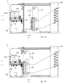
- Figs. 1a, 1b are used to describe embodiments of a machine 10 used to carry out works of cutting and/or continuous and/or discontinuous toothed creasing, and/or pre-creasing, on a relatively rigid material, in this case a sheet 12 of cardboard, for example a single sheet, a sheet of a continuous module but also a portion of a strip, a sheet coming from a pile, or two or more sheets coming from two or more piles and fed in parallel to the machine 10.
- a sheet 12 of cardboard for example a single sheet, a sheet of a continuous module but also a portion of a strip, a sheet coming from a pile, or two or more sheets coming from two or more piles and fed in parallel to the machine 10.
- the continuous or discontinuous toothed creasing, or the cutting, carried out on the sheet 12 of cardboard by the machine 10 are intended to promote the precise and linear folding of the cardboard, for example in the steps of automated production of a box for packaging.
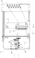
- the machine 10 comprises a support structure 14, disposed transverse with respect to a direction of feed F of the sheets 12.
- At least two longitudinal operating groups 16 for cutting and/or continuous or discontinuous toothed creasing, or pre-creasing are mounted on the support structure 14 and are disposed in sequence with respect to each other.
- a transverse operating group 18 for cutting and/or creasing, or pre-creasing, is also mounted on the support structure 14, positioned upstream of the two longitudinal operating groups 16.
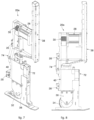
- Each longitudinal operating group 16 and the transverse operating group 18 comprise a plurality of operating units 20 to work a relatively rigid material.
- the operating units 20 have common characteristics and components and are then distinguished on the basis of installation and functional requirements, specific to the longitudinal operating groups 16 and the transverse operating group 18, respectively in longitudinal operating units 20a and transverse operating units 20b as described hereafter.
- Each operating unit 20 is suitable to support, move and command a corresponding cutting tool 32 or, alternatively, a corresponding continuous toothed creasing tool 34.
- the operating unit 20 can be able to support, move and command another discontinuous toothed creasing tool 42, able to perform a different and distinct work from the continuous toothed creasing tool 34.
- Each operating unit 20 also comprises a support flange 36 able to support the cutting tool 32, or continuous toothed creasing tool 34, or discontinuous toothed creasing tool 42, in order to determine the operating descent pressure of the corresponding work tool 32, or 34, or 42 on the sheet 12, and also a pneumatic condition of ascent from the sheet 12 of the corresponding work tool 32, or 34, or 42.
- each operating unit 20 is moved individually and independently from the others in order to position the corresponding cutting tool 32 and/or continuous toothed creasing tool 34 and/or discontinuous toothed creasing tool 42 in a determinate predefined working position.
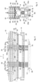
- the operating unit 20 comprises a pneumatic drive unit 40.
- the pneumatic drive unit 40 comprises two pairs of pneumatic drive members 46.
- Each pair of pneumatic drive members 46 is provided with two double-effect pistons 48 configured to work parallel in tandem, or to operate in the same pneumatic conditions of descent or ascent, at a determinate moment of time.
- the two pairs of pneumatic drive members 46 are also configured to operate in tandem at a determinate moment of time.
- Each piston 48 provides a cylinder 50 made of metal material and configured to operate at high pressures.
- Each cylinder 50 is configured to have two internal guide bushings 52 and mobile elements, or packings 54 installed inside it.
- the guide bushings 52 are made of metal material and configured to adhere perfectly and solidly to the internal walls of each cylinder 50.
- the guide bushings 52 are associated with the ends of each cylinder 50 and half way along it, thus defining the two double-effect pistons 48 of each pair of pneumatic drive members 46.
- the guide bushings 52 are configured to have circular grooves 56 and vertical grooves 58.
- the guide bushings 52 allow to guarantee stability to the structure of the pneumatic drive unit 40 in the event that the sheet 12 is not perfectly aligned in the direction of feed F and thus it is able to avoid incorrect workings or misalignments of the operating unit 20.
- each operating unit 20 goes from 20 mm to 40 mm, in particular from 25 mm to 35 mm.
- the two pairs of pneumatic drive members 46 allow to transmit to the cutting tool 32, to the continuous toothed creasing tool 34, to the discontinuous toothed creasing tool 42 an adequate pressure to contrast the resistance forces generated by the sheet 12.
- the packings 54 are configured to guarantee the seal between two chambers of each piston 48.
- the packings 54 can be the double-lip type.
- the packings 54 are mobile and associated with a rod 68 to transfer a movement of descent, or ascent, to the cutting tool 32 and/or the continuous toothed creasing tool 34 and/or the discontinuous toothed creasing tool 42.
- the rod 68 is through inside the guide bushings 52 installed halfway along the cylinders 50 and on the end near to the work tools 32, 34, 42. Moreover, each rod 68 cooperates with the flanges 36 in order to determine the pneumatic conditions of descent or ascent.
- each cylinder 50 The cooperation of the guide bushings 52 with the packings 54 inside each cylinder 50 defines a tool descent chamber 64 and a tool ascent chamber 66 with a variable volume depending on the position where the packings 54 together with the rod 68 are.
- the pneumatic drive unit 40 comprises a pneumatic tool-descent circuit 60 and a pneumatic tool-ascent circuit 62.
- a pressurized fluid for example air at high pressure, passes through the pneumatic tool-descent circuit 60 and the pneumatic tool-ascent circuit 62.
- the pneumatic tool-descent circuit 60 supplies the pressurized fluid and connects with respect to each other the tool descent chambers 64 of each piston 48.
- the pneumatic tool-ascent circuit 62 supplies the pressurized fluid and connects the tool ascent chambers 66 of each piston 48 with respect to each other.
- a feed pipe 70 is provided that receives the pressurized fluid from a pressurized fluid delivery device (not shown).
- the pneumatic drive unit 40 comprises a switching valve 72 installed in correspondence to the feed pipe 70.
- the switching valve 72 is connected to the pneumatic tool-descent circuit 60 and to the pneumatic tool-ascent circuit 62.
- the switching valve 72 can be, for example, the 5/2 monostable, or 4/2 bistable, or 3/2 type, and is configured to determine the pneumatic condition of descent of the work tools 32, 34, 42 or the pneumatic condition of ascent of the work tools 32, 34, 42.
- the switching valve 72 is assembled directly on board the pneumatic drive unit 40 and allows to have shorter response times to determine the pneumatic conditions of descent or ascent of the two pairs of pneumatic drive members 46 and therefore of the work tools 32, 34, 42.
- the pneumatic drive unit 40 can comprise a pneumatic brake 74.
- the pneumatic brake 74 is installed in correspondence to the side opposite the switching valve 72 and is connected to the pneumatic tool-descent circuit 60.
- the pneumatic brake 74 in the pneumatic condition of descent is driven by the pressurized fluid coming from the pneumatic tool-descent circuit 60, to block the operating unit 20 from possible forces generated during the working of the sheet 12 in the transverse direction T.
- the operating units 20 thus configured can be installed with less bulk and are thus lighter and so increase the accelerations and de-accelerations and therefore render the fitting out operations quicker.
- the pneumatic condition of descent of the cutting tool 32 or the continuous toothed creasing tool 34 or the discontinuous toothed creasing tool 42 is obtained by emitting pressurized fluid from the feed pipe 70 to the switching valve 72 that determines the circulation of the pressurized fluid in the pneumatic tool-descent circuit 60 to feed the tool descent chambers 64 of the two pairs of pneumatic drive members 46.
- the pressurized fluid flows from the circular grooves 56 and then through the vertical grooves 58 to feed the tool descent chambers 64.
- Pressurized fluid in the tool descent chambers 64 causes the descent of the packings 54 and therefore also of the rods 68 in order to transfer the movement under pressure to the work tools 32, 34, 42.
- the pneumatic condition of ascent of the cutting tool 32, or the continuous toothed creasing tool 34 or the discontinuous toothed creasing tool 42 occurs, wherein the switching valve 72 diverts the pressurized fluid in the pneumatic tool-ascent circuit 62 in order to feed the tool ascent chambers 66. At the same time, the switching valve 72 allows the pressurized fluid contained in the tool descent chambers 64 to complete the inverse travel in the pneumatic tool-descent circuit 60.
- each longitudinal operating group 16 comprises a plurality of longitudinal operating units 20a independent from each other and mobile in a direction T transverse to the direction of feed F of the sheet 12, along corresponding support cross-pieces 22 of the support structure 14.
- each longitudinal operating unit 20a is mounted sliding on the corresponding support cross-piece 22 by means of corresponding linear guides 24 and blocks 26.
- each longitudinal operating unit 20a with respect to the corresponding support cross-piece 22 is obtained by means of a motor member 28 mounted on board each longitudinal operating unit 20a and kinematically connected to the support cross-piece 22 by means of a gear mechanism with belt on a pinion 30.
- the gear mechanism with belt on a pinion 30 allows to have a quieter, quicker and more precise fitting-out step of the longitudinal operating group 16, which also does not need lubrication. Therefore, the gear mechanism with belt on a pinion 30 is also exempt from maintenance.
- the independent movement of the longitudinal operating group 16 allows to have quicker fitting-out operations.
- the longitudinal operating units 20a are conformed to maintain the corresponding cutting tool 32, continuous toothed creasing tool 34 or discontinuous toothed creasing tool 42, so that one or the other of the latter operate according to a direction substantially longitudinal to the direction of feed F of the sheet 12.
- each longitudinal operating group 16 has corresponding longitudinal operating units 20a with, respectively, for the first longitudinal operating group 16 cutting tools 32, and for the second longitudinal operating group 16 tools for continuous toothed creasing 34, or tools for discontinuous toothed creasing 42.
- each longitudinal operating group 16 are disposed aligned with each other with respect to the direction of feed F of the sheet 12, so as to be able to carry out in sequence, and in an aligned manner, the operations of cutting and/or continuous or discontinuous toothed creasing, and/or pre-creasing as provided.
- the longitudinal operating units 20a have a support structure 38 configured to reduce the bulk of each longitudinal operating unit 20a and thus maximize the number of longitudinal operating units 20a that can be installed for each longitudinal operating group 16.
- the support structure 38 allows to support the motor member 28, installed in each longitudinal operating unit 20a, and to dispose it offset with respect to the adjacent motor members 28 of each longitudinal operating unit 20a, thus being able to reduce the bulk.
- the profile of the support structure 38 is configured to maximize the adjacent positioning of the plurality of longitudinal operating units 20a.
- This aspect advantageously allows to be able to work a wide range of containers, of different format and workings, obtained through cutting and/or continuous and/or discontinuous toothed creasing and/or pre-creasing of sheets 12.
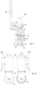
- the transverse operating group 18 comprises a plurality of transverse operating units 20b, also in this case, mobile independently from each other and suitable to support, move and command a corresponding cutting tool 32, or alternatively, a corresponding continuous toothed creasing tool 34 or discontinuous toothed creasing tool 42.
- the transverse operating group 18 can provide a transverse operating unit 20b to support, move and command another discontinuous toothed creasing tool 42.
- transverse operating units 20b are conformed to hold the corresponding cutting tool 32, or continuous toothed creasing tool 34 or discontinuous toothed creasing tool 42 so that one or the other of the latter operate according to a direction T substantially transverse to the direction of feed F of the sheet 12.
- the addition of another work tool allows to increase the combination of workings that can be carried out on a sheet 12 in order to obtain the desired container.
- the movement in the transverse direction T of the transverse operating units 20b is carried out by means of a motor member 44 mounted on board the transverse operating group 18.
- the transverse operating units 20b are moved by a gear mechanism with belt on a pinion 30, in order to position the corresponding cutting tool 32 and/or continuous toothed creasing tool 34, and/or discontinuous toothed creasing tool 42 in a determinate pre-defined work position.
- the motor member 44 of the brushless type is mounted on board the transverse operating group 18 and kinematically connected to the support cross-piece 22 by means of the gear mechanism with belt on a pinion 30.
- the gear mechanism with belt on a pinion 30 driven by the motor member 44 allows to obtain a more rapid transverse working of cutting and/or continuous or discontinuous toothed creasing, and/or pre-creasing, since this type of operation is characterized by a static feed.
- the gear mechanism with belt on a pinion 30 brings the same advantages described for the longitudinal operating groups 16.
- the speed of the transverse operating group 18 goes from 80 m/min to 115 m/min, in particular from 90 m/min to 110 m/min.
- the transverse operating group 18 can provide a secondary belt 76 attached to the support structure 14.
- the secondary belt 76 is associated with the cutting tool 32 and/or continuous toothed creasing tool 34 and/or discontinuous toothed creasing tool 42 by means of an "omega" shaped connection.
- the rectilinear movement of the transverse operating units 20b in the transverse direction T transmits the rotation motion to the work tools 32, 34, 42 thanks to the "omega" shaped connection.
- the machine 10 also comprises one or more control and command units 110, not shown, which are electronically connected to the movement members of each operating unit 20, in order to coordinate, according to a desired operating program, the positions and drives of each single cutting tool 32, and/or continuous toothed creasing tool 34 and/or discontinuous toothed creasing tool 42.
- one or more control and command units 110 can be installed on board in an ergonomic manner and accessible from the outside through protections made of transparent material, for example plastic.
- the machine 10 also comprises a drawing unit 80 able to move the sheet 12 ( figs. 11-15 , 16 ).
- the drawing unit 80 comprises a plurality of movement rollers 78 disposed on the side opposite the longitudinal operating groups 16 and the transverse operating group 18 with respect to a hypothetical horizontal feed plane of the sheet 12.
- the movement rollers 78 determine the feed of the sheet 12 in the direction of feed F in cooperation with the longitudinal operating groups 16 and the transverse operating group 18.
- the movement rollers 78 also have the function of contrasting the action of cutting and/or continuous and/or discontinuous toothed creasing, and/or pre-creasing carried out by the work tools 32, 34, 42.
- the movement rollers 78 can be made of both rubber and iron, for example to carry out cutting operations on iron.
- the drawing unit 80 is moved by a gear mechanism with belt 82 and is driven by an electric motor member 112 of the brushless type.
- This aspect allows to obtain a more silent movement and does not need maintenance, as well as guaranteeing greater speed in the drawing of the sheet 12.
- the drawing speed goes from 45 m/min to 65 m/min, in particular from 50 m/min to 60 m/min.
- the drawing unit 80 can be associated with an extraction unit 84 to expel the sheet 12 once the cutting and/or continuous and/or discontinuous toothed creasing and/or pre-creasing operations have been terminated.
- the extraction unit 84 provides a central support 86 to support an extraction element 88.
- the central support 86 is associated with a gear mechanism with belt 90 driven by an electric motor member.
- the drawing unit 80 and the extraction unit 84 can be driven by the same electric motor member 112.
- the extraction unit 84 provides at least two movement belts 92 ( fig. 17 ) able to discharge work offcuts of the sheet 12.
- the extraction element 88 is lowered by the central support 86 to direct the offcut downward, guided by the movement belts 92.
- the machine 10 can comprise a feed/introduction unit of the sheets 12 directly installed in the machine 10.
- the feed/introduction unit allows the correct introduction of the sheets 12 by driving an electric motor member of the brushless type.
- the electric motor member of the feed/introduction unit is completely autonomous from the electric motor member 112 of the drawing unit 80, thus allowing to be able to carry out completely autonomously and sequentially the operations necessary for the introduction of a new sheet 12 with respect to the cutting and/or continuous and/or discontinuous toothed creasing, and/or pre-creasing workings.
- the machine 10 can be associated with a loading device, or selector 94 for the automatic loading of the sheets 12 to be worked in the machine 10.
- the loading device 94 comprises a multiple introducer device 96 able to selectively introduce a plurality of sheets 12 toward the drawing unit 80.
- the multiple introducer device 96 comprises at least its own electric motor member of the brushless type in order to translate in a lifting direction Z transverse to the direction of feed F of the sheet 12.
- the multiple introducer device 96 comprises at least its own electric motor member of the brushless type to feed the sheet 12.
- the electric motor member 112 of the drawing unit 80 is completely autonomous from the electric motor member of the brushless type of the multiple introducer device 96.
- the loading device 94 provides to load a new sheet 12 removed from the store.
- the loading device 94 is provided with another electric motor member of the brushless type configured to determine a forward/backward translation in a direction of translation X parallel to the direction of feed F.
- the electric motor member allows to distance the loading device 94 from the machine 10 to a sufficient distance to allow an operator to carry out short maintenance interventions, for example, to remove the sheets 12 that obstruct the multiple introducer device 96.
- the machine 10 can be provided with a guard 100 to cover and protect it.
- the guard 100 can be made of metal material, for example of thin metal sheets, of 2 mm to 5 mm for example, obtained by laser cutting and cooperating with each other by means of jointing and/or welding.
- the guard 100 can be partly or completely made of plastic, carbon or a composite material.
- the guard 100 is provided with front guards 100a and lateral guards 100b.
- the lateral guards 100b are provided with opening hinges to allow to easily replace the components of the longitudinal operating groups 16, or the transverse operating group 18 by means of lateral extraction from the machine 10.
Landscapes
- Engineering & Computer Science (AREA)
- Mechanical Engineering (AREA)
- Life Sciences & Earth Sciences (AREA)
- Forests & Forestry (AREA)
- Machines For Manufacturing Corrugated Board In Mechanical Paper-Making Processes (AREA)
- Making Paper Articles (AREA)
- Details Of Cutting Devices (AREA)
- Control Of Cutting Processes (AREA)
- Folding Of Thin Sheet-Like Materials, Special Discharging Devices, And Others (AREA)
Claims (12)
- Eine Maschine zum Bearbeiten eines relativ starren Materials, umfassend:- eine Stützstruktur (14), die quer zu einer Zuführrichtung (F) eines Blattes (12) angeordnet ist;- eine Zieheinheit (80), die ein Blatt (12) aus relativ starrem Material in die Zuführrichtung (F) bewegen kann;- mindestens zwei Längsbetriebsgruppen (16) zum Schneiden, Rillen und Vorrillen des Blattes (12) aus relativ starrem Material, die auf der Stützstruktur (14) montiert und in Bezug zueinander in einer Reihenfolge angeordnet sind, um in einer Richtung zu arbeiten, die im Wesentlichen parallel zu der Zuführrichtung (F) ist;- eine Querbetriebsgruppe (18) zum Schneiden, Vorrillen und Rillen des Blattes (12) aus relativ starrem Material, die auf der Stützstruktur (14) montiert ist und vor den Längsbetriebsgruppen (16) positioniert ist, um in einer Querrichtung (T) zu arbeiten, die im Wesentlichen quer zu der Zuführrichtung (F) ist;wobei jede Längsbetriebsgruppe (16) eine Vielzahl von Längsbetriebseinheiten (20a) umfasst, die ein Arbeitswerkzeug stützen, bewegen und steuern, und die Querbetriebsgruppe (18) eine Vielzahl von Querbetriebseinheiten (20b) umfasst, die ein Arbeitswerkzeug stützen, bewegen und steuern,wobei die Längs- und Querbetriebseinheiten (20a, 20b) unabhängig voneinander und in der Querrichtung (T) beweglich sind, wobei das Arbeitswerkzeug ein Schneidwerkzeug (32) oder ein kontinuierliches Rillwerkzeug (34) oder ein diskontinuierliches Rillwerkzeug (42) umfasst;wobei jede der Längs- und Querbetriebseinheiten (20a, 20b) eine jeweilige pneumatische Antriebseinheit (40) zum Fördern der Abwärts- oder Aufwärtsbewegung des entsprechenden Arbeitswerkzeugs (32, 34, 42) aufweist;wobei jede pneumatische Antriebseinheit (40) zwei Paare pneumatischer Antriebselemente (46) umfasst, die jeweils mit zwei Doppelwirkungskolben (48) ausgestattet sind, die so konfiguriert sind, dass sie parallel und im Tandem arbeiten, wobei die pneumatische Antriebseinheit (40) mit einem pneumatischen Werkzeugabsenkkreis (60) und einem pneumatischen Werkzeugaufstiegskreis (62) ausgestattet ist, die beide in der Lage sind, den Doppelwirkungskolben (48) eine unter Druck stehende Flüssigkeit zuzuführen;dadurch gekennzeichnet, dass stromaufwärts des pneumatischen Werkzeugabsenkkreises (60) und des pneumatischen Werkzeugaufstiegkreises (62) eine Zufuhrleitung (70) vorgesehen ist, die mit einer Druckflüssigkeitszufuhrvorrichtung verbunden ist, wobei ein Schaltventil (72) in Übereinstimmung mit der Zufuhrleitung (70) installiert und direkt an Bord der pneumatischen Antriebseinheit (40) montiert ist, um eine Verbindung mit dem pneumatischen Werkzeugabsenkkreis (60) und dem pneumatischen Werkzeugaufstiegkreis (62) herzustellen, um einen pneumatischen Absenk- oder Aufstiegszustand der beiden Paare pneumatischer Antriebselemente (46) und der jeweiligen Werkzeuge (32, 34, 42) zu bestimmen und die Reaktionszeiten bei der Bestimmung der pneumatischen Zustände zu verkürzen.
- Maschine nach Anspruch 1, dadurch gekennzeichnet, dass die pneumatische Antriebseinheit (40) eine Führungsbuchse (52) umfasst, die mit den Doppelwirkungskolben (48) jedes pneumatischen Antriebselements (46) verbunden ist.
- Maschine nach Anspruch 1, dadurch gekennzeichnet, dass die pneumatische Antriebseinheit (40) eine pneumatische Bremse (74) umfasst, die mit dem pneumatischen Werkzeugabsenkkreis (60) verbunden ist.
- Maschine nach Anspruch 1, dadurch gekennzeichnet, dass jede der Betriebseinheiten (20a, 20b) ml einen Stützflansch (36) zum Stützen des Arbeitswerkzeugs (32, 34, 42) und der pneumatischen Antriebseinheit (40) umfasst.
- Maschine nach Anspruch 1, dadurch gekennzeichnet, dass sie einen Getriebemechanismus mit Riemen auf einem Ritzel (30) umfasst, der von einem Motor (28, 44) angetrieben wird und so konfiguriert ist, dass er die Vielzahl der Längsbetriebseinheiten (20a) und die Vielzahl der Querbetriebseinheiten (20b) bewegt.
- Maschine nach Anspruch 1, dadurch gekennzeichnet, dass sie einen Getriebemechanismus mit Riemen (82) umfasst, der so konfiguriert ist, dass er die Zieheinheit (80) bewegt, und der von einem Elektromotorelement (112) des bürstenlosen Typs angetrieben wird, das mit einer Extraktionseinheit (84) zusammenwirkt.
- Maschine nach Anspruch 6, dadurch gekennzeichnet, dass sie eine Mehrfacheinführvorrichtung (96) umfasst, die in der Lage ist, eine Vielzahl von Blättern (12) selektiv in die Zieheinheit (80) einzuführen, wobei die Mehrfacheinführvorrichtung (96) mindestens ein eigenes Elektromotorelement des bürstenlosen Typs umfasst, um das Blatt (12) zuzuführen, wobei das Elektromotorelement (112) der Zieheinheit (80) in Bezug auf den bürstenlosen Elektromotor der Mehrfacheinführvorrichtung (96) vollständig autonom ist.
- Maschine nach Anspruch 7, dadurch gekennzeichnet, dass die Mehrfacheinführvorrichtung (96) mit einem weiteren Elektromotorelement versehen ist, das so konfiguriert ist, dass es eine Vorwärts-/Rückwärtsverschiebung in einer Verschiebungsrichtung (X) parallel zur Zuführrichtung (F) bestimmt.
- Maschine nach Anspruch 1, dadurch gekennzeichnet, dass sie eine Extraktionseinheit (84) umfasst, die mit einem Getriebemechanismus mit einem Riemen (90) verbunden ist, der von dem Motorelement (112) der Zieheinheit (80) angetrieben wird, wobei die Extraktionseinheit (84) mindestens zwei Bewegungsriemen (92) umfasst, die in der Lage sind, Arbeitsabfälle der Blätter (12) abzuführen.
- Maschine nach Anspruch 1, dadurch gekennzeichnet, dass die Querbearbeitungsgruppe (18) mit einem Sekundärriemen (76) versehen ist, der mit dem Schneidwerkzeug (32) und/oder mit dem Werkzeug zum kontinuierlichen gezahnten Rillen (34) und/oder mit dem Werkzeug zum diskontinuierlichen gezahnten Rillen (42) mittels einer Omega-förmigen Verbindung verbunden ist, um die Drehbewegung, die durch die Bewegung der Querbearbeitungseinheiten (20b) in der Querrichtung (T) entsteht, auf die Arbeitswerkzeuge (32, 34, 42) zu übertragen.
- Maschine nach Anspruch 1, dadurch gekennzeichnet, dass sie eine oder mehrere Steuer- und Befehlseinheiten (110) umfasst, die ergonomisch an Bord installiert und von außen zugänglich sind.
- Maschine nach Anspruch 1, dadurch gekennzeichnet, dass jede Längsbetriebseinheit (20a) eine Stützstruktur (38) aufweist, die dazu ausgebildet ist, die Masse jeder Betriebseinheit (20a) zu verringern und die Anzahl der Längsbetriebseinheiten zu maximieren, die in jeder entsprechenden Längsbetriebsgruppe (16) installiert werden können, wobei die Stützstruktur (38) es ermöglicht, den in jeder Längsbetriebseinheit (20a) installierten Motor (28) zu stützen und ihn in Bezug auf den benachbarten Motor (28) jeder Längsbetriebseinheit (20a) versetzt anzuordnen.
Applications Claiming Priority (2)
| Application Number | Priority Date | Filing Date | Title |
|---|---|---|---|
| ITUB20151467 | 2015-06-17 | ||
| PCT/IB2016/053582 WO2016203424A1 (en) | 2015-06-17 | 2016-06-16 | Pneumatic drive unit for a work tool of a relatively rigid material and corresponding machine for working a relatively rigid material |
Publications (3)
| Publication Number | Publication Date |
|---|---|
| EP3310567A1 EP3310567A1 (de) | 2018-04-25 |
| EP3310567C0 EP3310567C0 (de) | 2024-10-23 |
| EP3310567B1 true EP3310567B1 (de) | 2024-10-23 |
Family
ID=55409934
Family Applications (1)
| Application Number | Title | Priority Date | Filing Date |
|---|---|---|---|
| EP16745159.0A Active EP3310567B1 (de) | 2015-06-17 | 2016-06-16 | Pneumatische antriebseinheit für ein arbeitswerkzeug aus einem relativ starren material und entsprechende maschine zum bearbeiten eines relativ starren materials |
Country Status (9)
| Country | Link |
|---|---|
| US (1) | US12036763B2 (de) |
| EP (1) | EP3310567B1 (de) |
| JP (1) | JP7065496B2 (de) |
| KR (1) | KR102646277B1 (de) |
| CN (1) | CN108136710B (de) |
| CA (1) | CA2989744C (de) |
| ES (1) | ES2991943T3 (de) |
| PL (1) | PL3310567T3 (de) |
| WO (1) | WO2016203424A1 (de) |
Families Citing this family (6)
| Publication number | Priority date | Publication date | Assignee | Title |
|---|---|---|---|---|
| ITUA20163729A1 (it) * | 2016-05-24 | 2017-11-24 | F L Auto Srl | Stazione di taglio di un foglio di cartone da una striscia continua di cartone e macchina per l’imballaggio di un articolo all’interno di una scatola di cartone ottenuta dal foglio di cartone |
| JP6927574B2 (ja) * | 2016-09-21 | 2021-09-01 | デュプロ精工株式会社 | スリッタ、シート裁断機、及びシート加工装置 |
| JP7322583B2 (ja) * | 2019-08-09 | 2023-08-08 | 株式会社リコー | シート加工装置、画像形成システム |
| JP7322584B2 (ja) * | 2019-08-09 | 2023-08-08 | 株式会社リコー | シート加工装置、画像形成システム |
| JP7322582B2 (ja) * | 2019-08-09 | 2023-08-08 | 株式会社リコー | シート加工装置、画像形成システム |
| CN112405688B (zh) * | 2019-08-20 | 2025-07-15 | 宁波经纬数控股份有限公司 | 一种送纸切割机 |
Citations (1)
| Publication number | Priority date | Publication date | Assignee | Title |
|---|---|---|---|---|
| DE102008014964A1 (de) * | 2007-03-30 | 2008-10-02 | Smc Corp. | Positionssteuermechanismus für doppelt wirkende Pneumatikzylinder |
Family Cites Families (31)
| Publication number | Priority date | Publication date | Assignee | Title |
|---|---|---|---|---|
| ITBS20010002A1 (it) * | 2001-01-11 | 2002-07-11 | Silvano Bacciottini | Macchina perfezionata per la cordonatura perforazione o taglio circolare di carta e simili |
| US3651723A (en) * | 1969-12-04 | 1972-03-28 | Harris Intertype Corp | Corrugated paperboard slitter-scorer |
| US3667222A (en) * | 1970-07-22 | 1972-06-06 | Illinois Tool Works | Power device |
| US3805652A (en) * | 1972-05-03 | 1974-04-23 | Ind Res & Eng Inc | Automatic tail cutter |
| DE2319436B2 (de) * | 1973-04-17 | 1976-08-26 | Transform Verstärkungsmaschinen AG, 6626 Bous | Werkzeugfuehrung einer leichtbaustanze |
| JPS53117174A (en) * | 1977-03-22 | 1978-10-13 | Sakunao Tanaka | Double cylinder structure and operating device thereof |
| ITMI20030043U1 (it) * | 2003-02-03 | 2004-08-04 | Cavagna Elio Srl | Supporto per la movimentazione lineare specie per unita' di taglio |
| IT1132882B (it) * | 1980-09-29 | 1986-07-09 | Elio Cavagna | Cordonatore comandabile ad aria compressa,ad olio o altro fluido,per stabilire o mutare la profondita' della cordonatura,trovante particolare impiego nella industria dei cartonaggi e degli imballaggi |
| JPH0224635Y2 (de) * | 1984-09-28 | 1990-07-05 | ||
| IT1177258B (it) * | 1984-11-19 | 1987-08-26 | Alfa Romeo Auto Spa | Attuatore autobloccante, a fluido |
| US4616815A (en) * | 1985-03-05 | 1986-10-14 | Vijuk Bindery Equipment, Inc. | Automatic stacking and folding apparatus |
| US5701727A (en) * | 1995-01-13 | 1997-12-30 | Datacard Corporation | Card affixing and form folding system |
| US5916079A (en) * | 1997-08-08 | 1999-06-29 | Delaware Capital Formation | Horizontal container forming machine |
| DE19754799A1 (de) * | 1997-12-10 | 1999-06-17 | Bhs Corr Masch & Anlagenbau | Längsschneide- und Rill-Maschine für Wellpappebahnen |
| US6840898B2 (en) * | 1998-10-09 | 2005-01-11 | Emsize Ab | Apparatus for the positioning of a tool or a tool holder in a machine designed for processing a sheet material |
| JP2002172585A (ja) * | 2000-12-06 | 2002-06-18 | Sanee Giken Kk | ラミネータのフィルム切断装置 |
| ATE432228T1 (de) * | 2001-12-20 | 2009-06-15 | Alessandro Cristofani | Wärmeschrumpfbare folienverpackung für flaschen und verfahren zu ihrer herstellung |
| CN2549266Y (zh) * | 2002-06-21 | 2003-05-07 | 焦益群 | 自动气控换向气缸 |
| DE102004046127A1 (de) * | 2004-09-23 | 2006-04-13 | Bhs Corrugated Maschinen- Und Anlagenbau Gmbh | Wellpappe-Anlage und Verfahren zur Herstellung von Wellpappe-Bögen |
| JP5174475B2 (ja) * | 2008-01-22 | 2013-04-03 | 京セラドキュメントソリューションズ株式会社 | 緩衝包装材 |
| JP5202060B2 (ja) * | 2008-03-24 | 2013-06-05 | 三菱重工印刷紙工機械株式会社 | スリッタ刃の高さ調整方法及び装置 |
| DE102008060073A1 (de) | 2008-12-02 | 2010-06-10 | Dgr-Graphic Gmbh | Rillung von Umschlägen in einem Klebebinder |
| ITBO20080733A1 (it) * | 2008-12-04 | 2010-06-05 | L C R Macchine Automatiche S R L | Macchina per la lavorazione di cartone e materiali simili. |
| EP2193890B1 (de) | 2008-12-08 | 2017-01-25 | Scandinavian Robotics AB | Vorrichtung zum Aufnehmen von Gegenständen |
| CN101475031B (zh) * | 2009-02-12 | 2010-08-25 | 大连工业大学 | 机器人爬梯装置 |
| IT1394812B1 (it) * | 2009-07-13 | 2012-07-13 | Panotec Srl | Macchina per il taglio e/o la cordonatura di un materiale relativamente rigido, quale ad esempio cartone, gruppo di taglio e/o cordonatura e relativo procedimento di taglio e/o cordonatura |
| US8500111B2 (en) * | 2011-01-24 | 2013-08-06 | Kabushiki Kaisha Toshiba | Sheet processing apparatus, image forming apparatus and sheet processing method |
| US9138905B2 (en) * | 2013-02-22 | 2015-09-22 | Valmet Technologies, Inc. | Method for calibrating the position of the slitter blades of a slitter-winder |
| US10245803B2 (en) * | 2013-03-13 | 2019-04-02 | Xerox Corporation | Apparatus, system and method for cutting and creasing media |
| CN106458481B (zh) * | 2014-06-25 | 2018-07-10 | 泛诺泰有限责任公司 | 用于制造包装用品的设备和方法 |
| JP6635344B2 (ja) * | 2014-07-02 | 2020-01-22 | パノテック エス.アール.エル. | 紙、段ボール、プラスチック材、複合材又はその種の比較的堅固な材料を切断するための切断装置 |
-
2016
- 2016-06-16 JP JP2017564731A patent/JP7065496B2/ja active Active
- 2016-06-16 CA CA2989744A patent/CA2989744C/en active Active
- 2016-06-16 CN CN201680043433.2A patent/CN108136710B/zh active Active
- 2016-06-16 EP EP16745159.0A patent/EP3310567B1/de active Active
- 2016-06-16 US US15/736,647 patent/US12036763B2/en active Active
- 2016-06-16 PL PL16745159.0T patent/PL3310567T3/pl unknown
- 2016-06-16 WO PCT/IB2016/053582 patent/WO2016203424A1/en not_active Ceased
- 2016-06-16 ES ES16745159T patent/ES2991943T3/es active Active
- 2016-06-16 KR KR1020187001171A patent/KR102646277B1/ko active Active
Patent Citations (1)
| Publication number | Priority date | Publication date | Assignee | Title |
|---|---|---|---|---|
| DE102008014964A1 (de) * | 2007-03-30 | 2008-10-02 | Smc Corp. | Positionssteuermechanismus für doppelt wirkende Pneumatikzylinder |
Also Published As
| Publication number | Publication date |
|---|---|
| ES2991943T3 (es) | 2024-12-05 |
| PL3310567T3 (pl) | 2025-02-03 |
| CN108136710A (zh) | 2018-06-08 |
| HK1251204A1 (zh) | 2019-01-25 |
| CA2989744A1 (en) | 2016-12-22 |
| JP2018527196A (ja) | 2018-09-20 |
| KR102646277B1 (ko) | 2024-03-08 |
| WO2016203424A1 (en) | 2016-12-22 |
| EP3310567C0 (de) | 2024-10-23 |
| JP7065496B2 (ja) | 2022-05-12 |
| EP3310567A1 (de) | 2018-04-25 |
| US20180178480A1 (en) | 2018-06-28 |
| KR20180054556A (ko) | 2018-05-24 |
| US12036763B2 (en) | 2024-07-16 |
| CN108136710B (zh) | 2021-03-12 |
| CA2989744C (en) | 2023-11-28 |
Similar Documents
| Publication | Publication Date | Title |
|---|---|---|
| EP3310567B1 (de) | Pneumatische antriebseinheit für ein arbeitswerkzeug aus einem relativ starren material und entsprechende maschine zum bearbeiten eines relativ starren materials | |
| EP2522580B1 (de) | Werkzeugwechseleinrichtung | |
| US9580193B2 (en) | Cutting station with complete cutting tool | |
| EP3047961B1 (de) | Schweiss- oder schneideeinheit für eine automatische form- und füllmaschine für flexible behälter | |
| ITUD20090132A1 (it) | Macchina per il taglio e/o la cordonatura di un materiale relativamente rigido, quale ad esempio cartone, gruppo di taglio e/o cordonatura e relativo procedimento di taglio e/o cordonatura | |
| US20100175350A1 (en) | Web Packaging System with Ergonomic Forming Plug Change | |
| US20100011718A1 (en) | Packaging machine having an adjustable pneumatic/hydraulic drive | |
| IT201800009060A1 (it) | Sistema di azionamento idraulico per un apparato di punzonatura | |
| KR100956185B1 (ko) | 헤비게이지 시어링장치 | |
| CN114769401A (zh) | 一种减少工件开裂的冲压设备 | |
| KR102400943B1 (ko) | 블로잉 수단 유닛 및 핫 포일 스탬핑 및 다이-절삭 디바이스 | |
| EP3127875A1 (de) | Schneidmaschine zum schneiden einer glasplatte | |
| US9573337B2 (en) | Deep-drawing packaging machine with lifting device | |
| US9446868B2 (en) | Packaging machine and packaging method with generation of pressurized air | |
| CN106044343A (zh) | 一种层叠式片料件规整设备 | |
| CN202186525U (zh) | 夹膜贴体包装机 | |
| EP1964654A2 (de) | Abrundungsmaschine für Holzpaneele | |
| CN104960840A (zh) | 焊接板输送线系统 | |
| CN102909749A (zh) | 具有压力空气操控的闭合框架的页张模切和/或压印机 | |
| KR101694339B1 (ko) | 블랭크 공급장치 | |
| EP4309860A1 (de) | Papierschneideeinheit mit benetzungseinheit und zugehörigem kontinuierlichen verpackungssystem | |
| EP2432635B1 (de) | Maschine zum schneiden und/oder bördeln eines relativ starren materials, etwa karton, und zugehöriges schneid- und/oder bördelverfahren | |
| CN102390558B (zh) | 夹膜贴体包装机 | |
| IT201900010191A1 (it) | Macchina per lavorare lamiere metalliche | |
| CN113696269A (zh) | 一种新型裁断机 |
Legal Events
| Date | Code | Title | Description |
|---|---|---|---|
| STAA | Information on the status of an ep patent application or granted ep patent |
Free format text: STATUS: THE INTERNATIONAL PUBLICATION HAS BEEN MADE |
|
| PUAI | Public reference made under article 153(3) epc to a published international application that has entered the european phase |
Free format text: ORIGINAL CODE: 0009012 |
|
| STAA | Information on the status of an ep patent application or granted ep patent |
Free format text: STATUS: REQUEST FOR EXAMINATION WAS MADE |
|
| 17P | Request for examination filed |
Effective date: 20180115 |
|
| AK | Designated contracting states |
Kind code of ref document: A1 Designated state(s): AL AT BE BG CH CY CZ DE DK EE ES FI FR GB GR HR HU IE IS IT LI LT LU LV MC MK MT NL NO PL PT RO RS SE SI SK SM TR |
|
| AX | Request for extension of the european patent |
Extension state: BA ME |
|
| DAV | Request for validation of the european patent (deleted) | ||
| RAX | Requested extension states of the european patent have changed |
Extension state: BA Payment date: 20180115 |
|
| STAA | Information on the status of an ep patent application or granted ep patent |
Free format text: STATUS: EXAMINATION IS IN PROGRESS |
|
| 17Q | First examination report despatched |
Effective date: 20190718 |
|
| GRAP | Despatch of communication of intention to grant a patent |
Free format text: ORIGINAL CODE: EPIDOSNIGR1 |
|
| STAA | Information on the status of an ep patent application or granted ep patent |
Free format text: STATUS: GRANT OF PATENT IS INTENDED |
|
| RIC1 | Information provided on ipc code assigned before grant |
Ipc: B31B 50/25 20170101ALI20240513BHEP Ipc: B31B 50/20 20170101ALI20240513BHEP Ipc: B31F 1/10 20060101ALI20240513BHEP Ipc: B26D 7/26 20060101ALI20240513BHEP Ipc: B26D 7/20 20060101ALI20240513BHEP Ipc: B26D 3/08 20060101ALI20240513BHEP Ipc: B26D 1/22 20060101ALI20240513BHEP Ipc: B31F 1/08 20060101AFI20240513BHEP |
|
| INTG | Intention to grant announced |
Effective date: 20240606 |
|
| GRAS | Grant fee paid |
Free format text: ORIGINAL CODE: EPIDOSNIGR3 |
|
| GRAA | (expected) grant |
Free format text: ORIGINAL CODE: 0009210 |
|
| STAA | Information on the status of an ep patent application or granted ep patent |
Free format text: STATUS: THE PATENT HAS BEEN GRANTED |
|
| RAP1 | Party data changed (applicant data changed or rights of an application transferred) |
Owner name: PANOTEC SRL |
|
| AK | Designated contracting states |
Kind code of ref document: B1 Designated state(s): AL AT BE BG CH CY CZ DE DK EE ES FI FR GB GR HR HU IE IS IT LI LT LU LV MC MK MT NL NO PL PT RO RS SE SI SK SM TR |
|
| REG | Reference to a national code |
Ref country code: GB Ref legal event code: FG4D |
|
| REG | Reference to a national code |
Ref country code: CH Ref legal event code: EP |
|
| REG | Reference to a national code |
Ref country code: DE Ref legal event code: R096 Ref document number: 602016089944 Country of ref document: DE |
|
| REG | Reference to a national code |
Ref country code: IE Ref legal event code: FG4D |
|
| REG | Reference to a national code |
Ref country code: ES Ref legal event code: FG2A Ref document number: 2991943 Country of ref document: ES Kind code of ref document: T3 Effective date: 20241205 |
|
| U01 | Request for unitary effect filed |
Effective date: 20241122 |
|
| U07 | Unitary effect registered |
Designated state(s): AT BE BG DE DK EE FI FR IT LT LU LV MT NL PT RO SE SI Effective date: 20241202 |
|
| PG25 | Lapsed in a contracting state [announced via postgrant information from national office to epo] |
Ref country code: IS Free format text: LAPSE BECAUSE OF FAILURE TO SUBMIT A TRANSLATION OF THE DESCRIPTION OR TO PAY THE FEE WITHIN THE PRESCRIBED TIME-LIMIT Effective date: 20250223 Ref country code: HR Free format text: LAPSE BECAUSE OF FAILURE TO SUBMIT A TRANSLATION OF THE DESCRIPTION OR TO PAY THE FEE WITHIN THE PRESCRIBED TIME-LIMIT Effective date: 20241023 |
|
| PG25 | Lapsed in a contracting state [announced via postgrant information from national office to epo] |
Ref country code: NO Free format text: LAPSE BECAUSE OF FAILURE TO SUBMIT A TRANSLATION OF THE DESCRIPTION OR TO PAY THE FEE WITHIN THE PRESCRIBED TIME-LIMIT Effective date: 20250123 |
|
| PG25 | Lapsed in a contracting state [announced via postgrant information from national office to epo] |
Ref country code: GR Free format text: LAPSE BECAUSE OF FAILURE TO SUBMIT A TRANSLATION OF THE DESCRIPTION OR TO PAY THE FEE WITHIN THE PRESCRIBED TIME-LIMIT Effective date: 20250124 |
|
| PG25 | Lapsed in a contracting state [announced via postgrant information from national office to epo] |
Ref country code: RS Free format text: LAPSE BECAUSE OF FAILURE TO SUBMIT A TRANSLATION OF THE DESCRIPTION OR TO PAY THE FEE WITHIN THE PRESCRIBED TIME-LIMIT Effective date: 20250123 |
|
| PG25 | Lapsed in a contracting state [announced via postgrant information from national office to epo] |
Ref country code: SM Free format text: LAPSE BECAUSE OF FAILURE TO SUBMIT A TRANSLATION OF THE DESCRIPTION OR TO PAY THE FEE WITHIN THE PRESCRIBED TIME-LIMIT Effective date: 20241023 |
|
| PGFP | Annual fee paid to national office [announced via postgrant information from national office to epo] |
Ref country code: GB Payment date: 20250617 Year of fee payment: 10 |
|
| PG25 | Lapsed in a contracting state [announced via postgrant information from national office to epo] |
Ref country code: SK Free format text: LAPSE BECAUSE OF FAILURE TO SUBMIT A TRANSLATION OF THE DESCRIPTION OR TO PAY THE FEE WITHIN THE PRESCRIBED TIME-LIMIT Effective date: 20241023 |
|
| PGFP | Annual fee paid to national office [announced via postgrant information from national office to epo] |
Ref country code: TR Payment date: 20250528 Year of fee payment: 10 |
|
| PGFP | Annual fee paid to national office [announced via postgrant information from national office to epo] |
Ref country code: CZ Payment date: 20250603 Year of fee payment: 10 |
|
| PGFP | Annual fee paid to national office [announced via postgrant information from national office to epo] |
Ref country code: IE Payment date: 20250617 Year of fee payment: 10 |
|
| U20 | Renewal fee for the european patent with unitary effect paid |
Year of fee payment: 10 Effective date: 20250624 |
|
| PLBE | No opposition filed within time limit |
Free format text: ORIGINAL CODE: 0009261 |
|
| STAA | Information on the status of an ep patent application or granted ep patent |
Free format text: STATUS: NO OPPOSITION FILED WITHIN TIME LIMIT |
|
| 26N | No opposition filed |
Effective date: 20250724 |
|
| PGFP | Annual fee paid to national office [announced via postgrant information from national office to epo] |
Ref country code: ES Payment date: 20250710 Year of fee payment: 10 |
|
| PGFP | Annual fee paid to national office [announced via postgrant information from national office to epo] |
Ref country code: PL Payment date: 20250523 Year of fee payment: 10 |
|
| PGFP | Annual fee paid to national office [announced via postgrant information from national office to epo] |
Ref country code: CH Payment date: 20250701 Year of fee payment: 10 |
|
| PG25 | Lapsed in a contracting state [announced via postgrant information from national office to epo] |
Ref country code: MC Free format text: LAPSE BECAUSE OF FAILURE TO SUBMIT A TRANSLATION OF THE DESCRIPTION OR TO PAY THE FEE WITHIN THE PRESCRIBED TIME-LIMIT Effective date: 20241023 |