EP3310531B1 - Abrasive article with abrasive particles having random rotational orientation within a range - Google Patents
Abrasive article with abrasive particles having random rotational orientation within a range Download PDFInfo
- Publication number
- EP3310531B1 EP3310531B1 EP16812207.5A EP16812207A EP3310531B1 EP 3310531 B1 EP3310531 B1 EP 3310531B1 EP 16812207 A EP16812207 A EP 16812207A EP 3310531 B1 EP3310531 B1 EP 3310531B1
- Authority
- EP
- European Patent Office
- Prior art keywords
- axis
- abrasive particles
- abrasive
- rotational orientation
- percent
- Prior art date
- Legal status (The legal status is an assumption and is not a legal conclusion. Google has not performed a legal analysis and makes no representation as to the accuracy of the status listed.)
- Active
Links
Images

Classifications
-
- B—PERFORMING OPERATIONS; TRANSPORTING
- B24—GRINDING; POLISHING
- B24B—MACHINES, DEVICES, OR PROCESSES FOR GRINDING OR POLISHING; DRESSING OR CONDITIONING OF ABRADING SURFACES; FEEDING OF GRINDING, POLISHING, OR LAPPING AGENTS
- B24B21/00—Machines or devices using grinding or polishing belts; Accessories therefor
- B24B21/04—Machines or devices using grinding or polishing belts; Accessories therefor for grinding plane surfaces
-
- B—PERFORMING OPERATIONS; TRANSPORTING
- B24—GRINDING; POLISHING
- B24D—TOOLS FOR GRINDING, BUFFING OR SHARPENING
- B24D11/00—Constructional features of flexible abrasive materials; Special features in the manufacture of such materials
-
- B—PERFORMING OPERATIONS; TRANSPORTING
- B24—GRINDING; POLISHING
- B24D—TOOLS FOR GRINDING, BUFFING OR SHARPENING
- B24D11/00—Constructional features of flexible abrasive materials; Special features in the manufacture of such materials
- B24D11/001—Manufacture of flexible abrasive materials
-
- B—PERFORMING OPERATIONS; TRANSPORTING
- B24—GRINDING; POLISHING
- B24D—TOOLS FOR GRINDING, BUFFING OR SHARPENING
- B24D13/00—Wheels having flexibly-acting working parts, e.g. buffing wheels; Mountings therefor
- B24D13/14—Wheels having flexibly-acting working parts, e.g. buffing wheels; Mountings therefor acting by the front face
-
- B—PERFORMING OPERATIONS; TRANSPORTING
- B24—GRINDING; POLISHING
- B24D—TOOLS FOR GRINDING, BUFFING OR SHARPENING
- B24D18/00—Manufacture of grinding tools or other grinding devices, e.g. wheels, not otherwise provided for
-
- B—PERFORMING OPERATIONS; TRANSPORTING
- B24—GRINDING; POLISHING
- B24D—TOOLS FOR GRINDING, BUFFING OR SHARPENING
- B24D3/00—Physical features of abrasive bodies, or sheets, e.g. abrasive surfaces of special nature; Abrasive bodies or sheets characterised by their constituents
-
- B—PERFORMING OPERATIONS; TRANSPORTING
- B24—GRINDING; POLISHING
- B24D—TOOLS FOR GRINDING, BUFFING OR SHARPENING
- B24D7/00—Bonded abrasive wheels, or wheels with inserted abrasive blocks, designed for acting otherwise than only by their periphery, e.g. by the front face; Bushings or mountings therefor
-
- B—PERFORMING OPERATIONS; TRANSPORTING
- B24—GRINDING; POLISHING
- B24D—TOOLS FOR GRINDING, BUFFING OR SHARPENING
- B24D2203/00—Tool surfaces formed with a pattern
Definitions
- US2013/0344786 discloses a coated abrasive article having a plurality of formed ceramic abrasive particles each having a surface feature wherein the surface feature has a specified z-direction rotational orientation, and wherein the specified z-direction rotational orientation occurs more frequently than would occur by a random z-direction rotational orientation of the surface feature.
- German Patent Publication 10 2013 212 609 discloses a method of producing an abrasive for which the abrasive particles are scattered on at least one abrasive backing characterized in that the abrasive particles are scattered at least partly aligned by at least one alignment aid.
- US 2014/106126 discloses an abrasive article according to the preamble of independent claims 1 and 9, namely an abrasive article including a backing, an adhesive layer on the backing, and groups of first and second abrasive particles overlying the backing, each placed in a non-shadowing arrangement relative to each other, wherein the each group of the first and the second abrasive particles have a predetermined rotational, lateral or longitudinal orientation.
- abrasive articles having abrasive particles with a selective z-direction rotational orientation can be difficult and/or expensive to produce, may not possess the desired degree of rotational orientation (i.e. the abrasive particles may possess too much or too little rotational orientation), and may be limited in terms of the type (e.g. size or shape) of abrasive particle that can be utilized in the construction of the abrasive article.
- an abrasive article that overcomes the shortcomings noted above. Accordingly, it would be desirable to provide an abrasive article, such as a coated abrasive article, having a selective z-direction rotational orientation that is easier and less expensive to produce, has abrasive particles with the desired degree of rotational orientation, and that can be produced using abrasive particles having a wide variety of sizes and shapes. More particularly, it would be desirable to provide an abrasive article having abrasive particles that are oriented in a controlled manner, and the angular orientation of at least a portion of the abrasive particles varies randomly within a defined range.
- the present invention solves the above problem by providing a coated abrasive article according to claim 1 and a circular abrasive disc according to claim 9.
- the abrasive article according to the embodiments described herein may be used to grind metal.
- the abrasive article may be in the form of a continuous belt, and the belt may be used to grind metal, such as titanium, by bringing the abrasive belt into contact with the metal.
- Length refers to the maximum caliper dimension of an object.
- Width refers to the maximum caliper dimension of an object perpendicular to the length axis.
- plate abrasive particle and particles described as having a “plate-like shape” refer to an abrasive particle resembling a platelet and/or flake that is characterized by a thickness that is less than the length and width.
- the thickness may be less than 1/2, 1/3, 1/4, 1/5, 1/6, 1/7, 1/8, 1/9, or even less than 1/10 of the length and/or width.
- crushed abrasive particle refers to an abrasive particle that is formed through a fracturing process such as a mechanical fracturing process.
- the material fractured to produce the crushed abrasive particle may be in the form of bulk abrasive or an abrasive precursor. It may also be in the form of an extruded rod or other profile or an extruded or otherwise formed sheet of abrasive or abrasive precursor.
- Mechanical fracturing includes, for example, roll or jaw crushing as well as fracture by explosive comminution.
- shaped abrasive particle refers to a ceramic abrasive particle with at least a portion of the abrasive particle having a predetermined shape that is replicated from a mold cavity used to form a precursor shaped abrasive particle which is sintered to form the shaped abrasive particle. Except in the case of abrasive shards (e.g., as described in U.S. Pat. No. 8,034,137 B2 (Erickson et al. )), the shaped abrasive particle will generally have a predetermined geometric shape that substantially replicates the mold cavity that was used to form the shaped abrasive particle.
- shaped abrasive particle as used herein excludes abrasive particles obtained by a mechanical crushing operation.
- an abrasive article such as a coated abrasive article, having a selective z-direction rotational orientation that is easier and less expensive to produce, has abrasive particles with a desired degree of rotational orientation, it can be produced using abrasive particles having a wide variety of sizes and shapes, and it produces a surprisingly uniform surface finish.
- the present invention provides an abrasive article having abrasive particles that are oriented in a controlled manner, and the angular orientation of at least a portion of the abrasive particles varies randomly within a defined range, thereby producing an abrasive article that has a surprisingly high cut rate and produces a smooth surface finish.
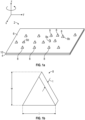
- FIG. 1a shows an abrasive article 2 comprising a backing or substrate 4 having a first major surface 6, and a plurality of abrasive particles 8 arranged on the first major surface 6 of the substrate 4.
- abrasive article 2 comprising a backing or substrate 4 having a first major surface 6, and a plurality of abrasive particles 8 arranged on the first major surface 6 of the substrate 4.
- the abrasive particles 8 may be bonded to the backing 4 using, for example, an optional adhesive make coat 10, or the abrasive particles 8 may be affixed directly to the backing 4.
- the abrasive article 2 is a coated abrasive product comprising a flexible backing layer 4 with abrasive particles 8 bonded to the first major surface 6 of the backing layer 4 via the make coat layer 10.
- the abrasive article 2 may include an optional size coat (not shown) applied over the abrasive particles 8.
- the make coat or size coat 10 is not critical to the invention hereof, so long as it provides the desired function and properties for the particular abrasive article and intended end use application.
- Suitable make and size coats include a wide variety of known resins including, for example, thermosetting resins such as phenolic resins, aminoplast resins, curable acrylic resins, cyanate resins, urethanes and combinations thereof.
- the particular backing or substrate 4 is not critical to the invention hereof, so long as it provides the desired function and properties for the particular abrasive article and intended end use application.
- Suitable backing materials include, for example, cloth, paper, polymeric films, nonwoven materials, vulcanized fiber materials, scrims and other web-like substrates.
- the abrasive article 2 comprises a single abrasive layer formed by the backing layer 4, make coat 10, and abrasive particles 8.
- the single abrasive layer may be converted into, for example, abrasive sheets, pads or discs.
- the abrasive article 2 may comprise a plurality of abrasive layers.
- the abrasive article 2 may comprise a nonwoven abrasive sheet that is spirally wound onto itself, thereby forming a convolute abrasive disc.
- the abrasive article may comprise a plurality of nonwoven abrasive sheet layers that are formed into abrasive "flaps" that are arranged radially around a hub to form a flap disc.
- the abrasive article 2 includes a y-axis corresponding to a longitudinal direction of the abrasive article 2, an x-axis corresponding to a transverse or lateral direction of the abrasive article 2 which is perpendicular to the y-axis, and a z-axis orthogonal to the y-axis and x-axis.
- the x-axis and y-axis define a plane that generally corresponds to the first major surface 6 of the abrasive article 2, and the z-axis extends outwardly from the x-y plane in the direction away from the first major surface 6 of the abrasive article 2.
- the abrasive article 2 comprises a backing 4 having a longitudinal axis y, a transverse axis x, and a make coat 10 on at of the first major surface 6 for securing the plurality of abrasive particles 8 to the backing 4.
- a portion of the abrasive particles 8 include a longitudinal axis extending in the direction of the y-axis of the backing 4, and a z-direction axis orthogonal to the y-axis of the backing 4.
- the z-axis rotational orientation of a majority of the abrasive particles 8 varies randomly within a defined range, and the spacing of the abrasive particles 8 in the y-direction varies randomly.
- the abrasive particle 8 has a generally triangular profile, and possesses a width "w", a length "l” and a thickness "t". In addition, the width w and length 1 dimensions of the abrasive particle 8 are greater than the thickness t dimension. It will be recognized, however, that a wide variety of abrasive particles may be utilized in the various embodiments described herein.
- the shaped abrasive particles according to the invention are triangular or star-shaped.
- abrasive particle 8 e.g. size, shape, chemical composition
- the particular type of abrasive particle 8 is not considered to be particularly significant to the abrasive article 2, so long as at least a portion of the abrasive particles 8 are capable of exhibiting and/or achieving the desired degree of rotational orientation.
- the abrasive particle may have a generally symmetric profile, include at least one point, and be capable of exhibiting rotational orientation.
- at least a portion of the abrasive particles 8 are elongate and are configured to be oriented in an upright position by passing them through an elongate slot.
- the abrasive article 2 may include a mixture of abrasive particles that are both capable of exhibiting the desired degree of rotational orientation together with abrasive particles that are not capable of exhibiting the desired degree of rotational orientation.
- suitable abrasive particles will possess an elongate edge and will be capable of being positioned upright on the elongate edge. More specifically, suitable abrasive particles may possess a length and thickness that define an elongate edge, or a width and thickness that define an elongate edge, and the length and width are each greater than the thickness. Configured as such, suitable abrasive particles may be described as having a plate-like shape, or as "platey abrasive particles.” Suitable platey abrasive particles include both crushed abrasive particles and shaped abrasive particles. Suitable abrasive particles also include abrasive agglomerates having plate-like shapes.
- the abrasive particles may include a surface feature.
- Surface features may include, for example, a substantially planer face, a substantially planar surface having a triangular or star-shaped perimeter, a concave surface, a convex surface, a vertex, an aperture, a ridge or raised line or plurality of lines, and/or a groove or channel or plurality of grooves or channels.
- Such surface features may be formed during the molding, extrusion, screen printing or other process that shapes the abrasive particles.
- such abrasive particles are arranged such that the z-direction rotational orientation of at least a portion of the abrasive particles varies randomly within a defined range.
- At least a portion of the abrasive particles include a base, and the abrasive particle is configured to rest on the base in an upright position so as to project outwardly from the substrate.
- the abrasive article 2 may include a mixture of different types of abrasive particles.
- the abrasive article 2 may include mixtures of platey and non-platey particles, crushed and shaped particles (which may be discrete abrasive particles that do not contain a binder or agglomerate abrasive particles that contain a binder), conventional non-shaped and non-platey abrasive particles (e.g. filler material) and abrasive particles of different sizes, so long as at least a portion of the abrasive particles have a plate-like shape or are otherwise capable of exhibiting the desired degree of rotational orientation.
- Suitable shaped abrasive particles can be found in U.S. Pat. Nos. 5,201,916 (Berg ); 5,366,523 (Rowenhorst ( Re 35,570 )); and 5,984,988 (Berg ).
- U.S. Pat. No. 8,034,137 (Erickson et al. ) describes alumina crushed abrasive particles that have been formed in a specific shape, then crushed to form shards that retain a portion of their original shape features.
- shaped alpha alumina particles are precisely-shaped (i.e., the particles have shapes that are at least partially determined by the shapes of cavities in a production tool used to make them).
- crushed abrasive particles include crushed abrasive particles comprising fused aluminum oxide, heat-treated aluminum oxide, white fused aluminum oxide, ceramic aluminum oxide materials such as those commercially available as 3M CERAMIC ABRASIVE GRAIN from 3M Company, St.
- sol-gel-derived abrasive particles from which crushed abrasive particles can be isolated and methods for their preparation can be found in U.S. Pat. Nos. 4,314,827 (Leitheiser et al. ); 4,623,364 (Cottringer et al. ); 4,744,802 (Schwabel ), 4,770,671 (Monroe et al. ); and 4,881,951 (Monroe et al. ).
- the crushed abrasive particles could comprise abrasive agglomerates such as, for example, those described in U.S. Pat. Nos. 4,652,275 (Bloecher et al. ) or 4,799,939 (Bloecher et al. ).
- the crushed abrasive particles comprise ceramic crushed abrasive particles such as, for example, sol-gel-derived polycrystalline alpha alumina particles.
- Ceramic crushed abrasive particles composed of crystallites of alpha alumina, magnesium alumina spinel, and a rare earth hexagonal aluminate may be prepared using sol-gel precursor alpha alumina particles according to methods described in, for example, U.S. Pat. No. 5,213,591 (Celikkaya et al. ) and U.S. Publ. Pat. Appln. Nos. 2009/0165394 A1 (Culler et al. ) and 2009/0169816 A1 (Erickson et al. ).
- Suitable platey crushed abrasive particles can be found in, for example, PCT Application Number PCT/US2016/022884 and U.S. Patent No. 4,848,041 (Kruschke ).
- the abrasive particles may be surface-treated with a coupling agent (e.g., an organosilane coupling agent) or other physical treatment (e.g., iron oxide or titanium oxide) to enhance adhesion of the crushed abrasive particles to the binder.
- a coupling agent e.g., an organosilane coupling agent
- other physical treatment e.g., iron oxide or titanium oxide
- the rotational orientation of at least a portion of the abrasive particles 8 about the z-axis varies randomly within a defined range. That is, the degree of z-direction rotational orientation of at least a portion of the abrasive particles 8 is constrained within a defined range, but within the defined range, the z-direction rotational orientation of the abrasive particles varies randomly. It will be recognized, however, that the abrasive article 2 may include a certain percentage of abrasive particles having a z-direction rotational orientation outside of the defined range without deviating from the scope of the invention as defined by the appended claims.
- abrasive particle labeled 8a is intended to represent an abrasive particle having a z-direction rotational orientation that is outside the defined range.
- the abrasive particles 8 have an average z-axis rotational orientation, and a defined percentage of abrasive particles has a z-axis rotational orientation within a defined range of the average z-axis rotational orientation.
- the abrasive particles 8 are generally arranged along a path 11a, 11b, 11c having an axis, and each abrasive particle 8 has a longitudinal axis, and the longitudinal axis of at least a portion of the abrasive particles is within a defined range relative to the axis of the paths 11a, 11b 11c. In the embodiment illustrated in FIG.
- the path 11a, 11b, 11c of abrasive particles is generally linear.
- the axis of each path 11a, 11b, 11c of abrasive particles generally corresponds to the longitudinal direction of the path.
- the axis of each path 11a, 11b, 11c of abrasive particles is generally aligned with the longitudinal axis of the abrasive article, which corresponds to the y-axis. It will be recognized, however, that the axis of each path 11a, 11b, 11c can be offset from the longitudinal axis (i.e. y-axis) of the abrasive article 2.
- the abrasive particles 8 can be applied to the backing 4 so as to form paths 11a, 11b, 11c that are diagonal to the longitudinal axis of the backing 4.
- the axis of the path will be tangent to the path at the location of the abrasive particle.
- the z-direction rotational orientation of at least 80 or 90 percent of the abrasive particles 8 is within about +/- 45 degrees of the average abrasive particle z-direction rotational orientation, at least about 40 percent, and no greater than 80 percent of the z-direction rotational orientation of the abrasive particles is within about +/- 30 degrees of the average particle z-direction rotational orientation, at least 30 percent and no greater than about 70 percent of the z-direction rotational orientation of the abrasive particles is within about +/- 20 degrees of the average particle z-direction rotational orientation, at least 15 percent and no greater than 40 percent of the z-direction rotational orientation of the abrasive particles is within about +/- 10 degrees of the average particle z-direction rotational orientation, and/or at least 10 percent and no greater than 25 percent of the z-direction rotational orientation of the abrasive particles is within about +/- 5 degrees of the average particle z-direction rotational
- the defined range of the rotational orientation of at least a portion of the abrasive particles 8 is constrained by a pair of imaginary boundaries 12a, 14a, 12b, 14b, 12c, 14c.
- the distance between the imaginary boundaries 12a, 14a, 12b, 14b, 12c, 14c is designated d1.
- the imaginary boundaries 12a, 14a, 12b, 14b, 12c, 14c define regions 16a, 16b, 16c, respectively, that generally constrain the z-direction rotational orientation of the abrasive particles 8 to an angle of less than the angle ⁇ ( Fig. 2a ).
- the degree of rotational orientation is determined in part by the size of the abrasive particle 8 (e.g. by the length l and the thickness t) and by the distance d1 between the pair of imaginary boundaries 12a, 14a, 12b, 14b, 12c, 14c.
- the imaginary boundaries 12a, 14a, 12b, 14b, 12c, 14c need not be linear or parallel. That is, the imaginary boundaries 12a, 14a, 12b, 14b, 12c, 14c may be, for example, arcuate, curved, serpentine or irregular, as long as the abrasive particles within the boundaries 12a, 14a, 12b, 14b, 12c, 14c possess the desired degree of z-direction rotational orientation.
- the abrasive particles 8 may be provided in a variety of patterns including, for example, wavy, sinusoidal, circular or in a random path. As described in more detail below, in the case of a wavy, sinusoidal, or circular path, the y-axis of the paths 11a, 11b, 11c is a tangent to the path at the location of the abrasive particle.
- the location of at least a portion of the abrasive particles is constrained by the distance d1 within the regions 16a, 16b, 16c.
- the spacing d2 between adjacent regions 16a, 16b, 16c may be controlled.
- the transverse position of at least a portion of the abrasive particles 8 is constrained within a range defined by the spacing distance d1 within a pair of imaginary boundaries, but within the range defined by d1, the transverse position of the abrasive particles 8 varies randomly.
- At least a portion of the abrasive particles 8 may be thought of as being arranged in rows and the average deviation of the location of an abrasive particle from the center of the row varies randomly within a defined range such as, for example, at least about 0.5, 1 or 1.5 times the thickness of the abrasive particle to no more than about +/- 3, 4 or 5 times the thickness of the abrasive particle 8.
- the x-axis spacing distance between adjacent regions 16a, 16b, 16c (d2) is not random.
- the spacing of the abrasive particles 8 in the x-axis direction is not random. That is, the average x-axis spacing distance between the abrasive particles 8 may vary randomly within a defined range. It will be recognized, however, that even when the abrasive particles 8 are generally arranged in discrete regions, the abrasive article 2 may also include abrasive particles that are outside the regions (i.e. outside the imaginary boundaries). For example, in the abrasive article 2 illustrated in FIGS.
- abrasive particle 8b is shown as lying outside the regions 16a, 16b, 16c defined by the imaginary boundaries 12a, 14a, 12b, 14b, 12c, 14c. Nevertheless, the z-direction rotational orientation of such an abrasive particle may be within the defined range of z-direction rotational orientation for the abrasive article 2.
- At least 90 percent of the abrasive particles in a defined region are spaced from the abrasive particles in an adjacent defined region by a distance of at least about 0.01, 0.5, 1, or 2 millimeters and by a distance of no greater than about 5, 7, or 10 millimeters. In another specific embodiment, at least 90 percent of the abrasive particles in a defined region are spaced by a distance of at least about the average thickness of the abrasive particles in an adjacent defined region, and by a distance of no greater than about 5, 7 or 10 times the average thickness of the abrasive particles.
- the x-axis spacing distance d1 of the abrasive particles 8 within a region will appear random because the location of the abrasive particles 8 within the regions 16a, 16b, 16c also varies in the x-axis direction. That is, when adjacent regions are sufficiently close together (e.g. as the distance d2 is decreases), the x-axis spacing distance d1 of the abrasive particles 8 within the regions will eventually be greater than the x-axis spacing d2 between adjacent region. When this happens (i.e.
- the spacing of the abrasive particles 8 in the x-axis direction appears random. Stated another way, when the variation in the x-axis position of the abrasive particles 8 within a region is greater than the spacing distance d2 between adjacent regions, the regularity of the x-axis spacing d2 between abrasive particles in adjacent region becomes undetectable.
- the x-axis spacing distance between abrasive particles may appear either random or appear to vary within a selected range. That is, if the x-axis spacing distance d2 between adjacent regions is sufficiently large compared to d1, the x-axis spacing distance between abrasive particles will appear to vary randomly within a defined range, and if the x-axis spacing distance d2 between adjacent imaginary boundaries is sufficiently small compared to d1, the x-axis spacing distance between abrasive particles will appear random.
- the distance d3 between adjacent abrasive particles 8 varies randomly along the y-axis. That is, the y-axis distance between adjacent abrasive particles 8 is not fixed, and there is no discernable pattern to the arrangement of the abrasive particles 8 in the y-axis direction. In certain embodiments, however, namely, those in which the x-axis spacing distance between abrasive particles appears to vary randomly within a defined range, the abrasive particles are spaced more uniformly in the x-axis direction than the y-axis direction.
- the abrasive article 2 may also include abrasive particles 8 that are not inclined relative to the substrate 4 (i.e. the abrasive particles 8 may lie flat on the substrate 4), and/or include abrasive particles 8 that are inclined at relatively small angles (e.g. less than 45 degrees) relative to the substrate 4.
- abrasive particle 8c is shown lying flat on its side.
- At least about 60, 70 or 80 percent of the abrasive particles are inclined at an angle of at least about 45 degrees from the plane defined by the x and y axes. In other embodiments, up to about 5, 10 or 15 percent of the abrasive particles are inclined at an angle of no greater than about 45 degrees from the plane defined by the x and y axes.
- a certain portion of the abrasive particles 8 may be positioned such that a point of the triangle, rather than an elongate edge, is affixed to the backing 4 (i.e. the triangular abrasive particle appears upside down).
- the percentage of abrasive particles arranged with a point affixed to the backing 4 rather than an elongate edge, will typically be less than about 2, 3, 4 or 5 percent.
- FIG. 3 there is shown an abrasive article 102 in which imaginary boundaries 112a, 114a, 112b, 114b, 112c, 114c define non-linear paths 118a, 118b, 118c, respectively.
- the abrasive article 102 comprises a backing 104 having a first major surface 106, and the imaginary boundaries 112a, 114a, 112b, 114b, 112c, 114c define serpentine, wavy or sinusoidal regions 116a, 116b, 116c where a plurality of abrasive particles 108 are secured to the backing 104 via an optional make coat (not shown).
- each abrasive particle 108 includes a first axis 120 tangent to the paths 118a, 118b, 118c (i.e. the "tangent axis") at the location of the abrasive particles 108.
- the abrasive article 102 further includes a transverse axis 122 orthogonal to the tangent axis 120, and a z-axis orthogonal to the tangent axis 120 and the transverse axis 122 (the z-axis is not shown because it extends directly outwardly from the plane of the page).
- the rotational orientation of a majority of the abrasive particles 108 about the z-axis varies randomly within a defined range
- the spacing distance d3 of the abrasive particles 108 along the paths 118a, 118b, 118c varies randomly
- the transverse spacing distance d2 between the regions 116a, 116b, 116c can be controlled.
- Creating a non-linear path of abrasive particles 108 may be accomplished, for example, by varying either the path or orientation of the backing 104 relative to a fixed stream of abrasive particles as the abrasive particles 108 are applied to the backing 104, or moving the stream of abrasive particles 108 relative to a fixed backing 104 as the abrasive particles 108 are applied to the backing 104.
- the wavy pattern depicted in FIG. 3 may be created by, for example, oscillating the backing 104 relative to the stream of abrasive particles.
- the backing 104 may also be vibrated to randomize the placement of the abrasive particles 108 on the backing 104.
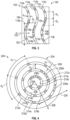
- an abrasive article in the form of a circular disc 224.
- the abrasive disc 224 comprises a backing 204 having a first major surface 206, and a plurality of abrasive particles 208 are secured to the backing 204 via an optional make coat (not shown).
- Imaginary boundaries 212a, 214a, 212b, 214b, 212c, 214c define annular paths 226a, 226b, 226c and further define annular regions 216a, 216b, 216c that generally constrain the location and rotational orientation of the abrasive particle 208.
- the abrasive disc 224 includes a first axis 220 tangent to the annular paths 226 at the location of the abrasive particles 208.
- the abrasive disc 224 further includes a radial axis 228 orthogonal to the tangent axis 220, and a z-axis orthogonal to the tangent axis 220 and the radial axis 228 (the z-axis is not shown because it extends directly outwardly from the plane of the page).
- the rotational orientation of a majority of the abrasive particles 208 about the z-axis varies randomly within a defined range
- the annular spacing distance d3 of the abrasive particles 208 along the paths 226a, 226b, 226c varies randomly
- the radial spacing distance d2 between the regions 216a, 216b, 216c can be controlled.
- the z-direction rotational orientation of abrasive particles varies within a defined range, and the spacing distance of the abrasive particles along a first major axis of an abrasive path varies randomly.
- the spacing distance of the abrasive particles along a second major axis orthogonal to the first major axis may vary randomly within a range or they may appear to vary randomly.
- the abrasive articles 2 may be formed by passing the abrasive particles 8 through an alignment device, whereby the abrasive particles 8 emerge from and impinge upon the substrate 4 with the desired degree of z-direction rotational orientation and/or placement.
- an external force e.g. gravity, electrostatic, centripetal
- the alignment device may comprise, for example, a plurality of elongate slots or openings formed by, for example, a plurality of wires or strings, a comb-like structure, or a plurality of walls that define elongate slots.
- the size and shape of the elongate slots may vary depending on the size and shape of the abrasive particles being applied to the substrate, and on the desired pattern of the abrasive particles to be applied to the substrate.
- the elongate slots may be, for example, straight, curved, or arcuate.
- the abrasive particles may be applied to or passed through the alignment device using, for example, forced air, by electrostatically propelling them, by dropping them on, for example, a rotating drum, or by gravity feeding them onto or through the alignment device.
- forced air by electrostatically propelling them
- dropping them on, for example, a rotating drum or by gravity feeding them onto or through the alignment device.
- Techniques useful for applying abrasive particles to the substrate are described in attorney docket numbers 76714US002 ( USSN 62/189,980 ), 76715US002 ( USSN 62/182,077 ) and 76698US002 ( 62/190,046 ).
- the alignment device may also comprise a screen or grid containing elongate openings.
- the elongate openings of such a screen or grid may be provided in any desired pattern.
- the abrasive article shown in FIG. 4 may be formed using an alignment device containing a plurality of concentric annular elongate slots that position the abrasive particles on the substrate.
- the alignment device is first positioned adjacent the substrate (the alignment device may either contact the substrate or be slightly spaced from the substrate).
- Abrasive particles are then arranged in the elongate slots by, for example, pouring the abrasive particles over the alignment device to at least partially fill the elongate slots.
- excess abrasive particles are removed from the alignment device. Once the abrasive particles are bonded to the substrate, the alignment device is separated or removed from the substrate. In this manner, the oriented abrasive particles are left on the substrate in a pattern that matches the pattern provided by the alignment device.
- a portion of the abrasive particles 8 may have an average volume of at least 2, 3, 5 or 7 cubic millimeters, and may have an average weight of at least about 0.5, 1, 2 or 3 milligrams.
- the abrasive articles according to the present disclosure may be converted into, for example, an endless or continuous belts, discs (including perforated discs), sheets and/or pads.
- two free ends of a sheet-like abrasive article may be joined together using known methods to form a spliced belt.
- the make coat may be provided as a layer across the entire first major surface of the abrasive article, it may be provided on only select regions of the first major surface, such as regions 16a, 16b and 16c, or the make coat may be applied directly to the abrasive particles prior to affixing the abrasive particles to the backing.
- the coating weight of the abrasive particles in the various embodiments described herein may range from at least about 1000, 1500 or 2000 grams/square meter (g/m 2 ), to no greater than about 4000, 4500 or 5000 g/m 2 .
- the abrasive articles described herein can be used for a variety of abrading applications including, for example, grinding, cutting and machining applications.
- the abrasive article is a coated abrasive belt used to grind metal, such as titanium or steel.
- the shaped abrasive particles were prepared by molding alumina sol gel in equilateral triangle-shaped polypropylene mold cavities of side length 0.11 inch (2.794 mm) and a mold depth of 0.028 inch (0.711 mm). After drying and firing, the resulting shaped abrasive particles were about 1.4 mm (side length) ⁇ 0.35 mm thick, with a draft angle approximately 98 degrees, and would pass through a 30-mesh USA Standard Testing Sieve.
- AP3 Aluminum oxide conforming the FEPA (Federation of the European Producers of Abrasives) standard for P60 obtained under trade designation "DURALUM” in grit size 60 from Washington Mills, Grafton, Massachusetts.
- Untreated polyester cloth having a basis weight of 300-400 g/m 2 obtained under the trade designation "POWERSTRAIT” from Milliken & Company, Spartanburg, South Carolina, was pre-sized at the basis weight of 113 g/m 2 with a composition consisting of 75 parts epoxy resin (bisphenol A diglycidyl ether, obtained under trade designation "EPON 828” from Resolution Performance Products, Houston, Texas), 10 parts of trimethylolpropane triacrylate (obtained under trade designation "SR351” from Cytec Industrial Inc., Woodland Park, New Jersey), 8 parts of dicyandiamide curing agent (obtained under trade designation "DICYANEX 1400B” from Air Products and Chemicals, Allentown, Pennsylvania), 5 parts of novolac resin (obtained under trade designation "RUTAPHEN 8656” from Momentive Specialty Chemicals Inc., Columbus, Ohio), 1 part of 2,2-dimethoxy-2-phenylacetophenone (obtained under trade designation "IRGACURE 651" photoin
- Abrasive particles AP1 were applied to the make resin-coated backing by passing the abrasive particles through an alignment device comprising a plurality of elongate slots. The lateral spacing or gap between adjacent elongate slots was 1.3 mm. The coating weight of AP1 was 1172 g/m 2 with a variation of ⁇ 42 g/m 2 over the sample. The abrasive coated backing was placed in an oven at 90 °C for 1.5 hours to partially cure the make resin.
- Example 2 The procedure generally described in Example 1 was repeated, with the exception that the abrasive particles AP1 were applied to the make resin-coated backing material via conventional drop coating.
- Example 2 The procedure generally described in Example 1 was repeated, with the exception that AP1 was replaced with AP2, the coating weight of AP2 was 607 g/m 2 with a variation of ⁇ 21 g/m 2 over the sample, and the lateral spacing along x-axis between adjacent elongate slots on the alignment device was 0.864 mm.
- Example 2 The procedure generally described in Example 2 was repeated, with the exception that the abrasive particles AP2 were applied to the make resin-coated backing material via electrostatic coating at a coating weight of 607 g/m 2 .
- Untreated polyester cloth having a basis weight of 300-400 g/m 2 obtained under the trade designation "POWERSTRAIT" was coated with 113 g/m 2 of pre-size resin with the same composition as described in Example 1.
- the cloth backing was then coated with 209 g/m 2 of a phenolic make resin with the same composition as that in Example 1.
- Abrasive particles AP2 were applied to the make resin-coated backing by passing the abrasive particles through an alignment device comprising a plurality of elongate slots. The lateral spacing or gap between adjacent elongate slots was 0.864 mm. The coating weight of AP2 was 334.8 g/m 2 with a variation of ⁇ 28.8 g/m 2 over the sample. Then the abrasive particles AP3 were applied to the AP2-coated backing material via electrostatic coating at a coating weight of 150.6 g/m 2 with a variation of ⁇ 13.0 g/m 2 over the sample. The abrasive coated backing was placed in an oven at 90 °C for 1.5 hours to partially cure the make resin.
- a size resin was applied to each strip of backing material at a basis weight of 502 g/m 2 .
- a size resin consists of 45.76 parts of resole phenolic resin (obtained as GP 8339 R-23155B from Georgia Pacific Chemicals), 4.24 parts of water, 48.26 parts of cryolite (Solvay Fluorides, LLC, Houston, Texas), and 1.75 parts red iron oxide.
- the coated strip was then placed in an oven at 90 °C for 1 hour, followed by 8 hours at 102 °C. After cure, the strip of coated abrasive was converted into a belt as is known in the art.
- Example 3 The procedure of preparing the pre-size coated, make resin coated cloth backing generally described in Example 3 was repeated.
- An abrasive particle mixture was prepared by thoroughly blending 69% of abrasive particles AP2 and 31% of abrasive particles AP3.
- the abrasive particle mixture was applied to the make resin-coated backing material via electrostatic coating at a coating weight of 485.5 g/m 2 with a variation of ⁇ 41.8 g/m 2 over the sample.
- the abrasive coated backing was then partially cured, coated with size resin, cured, and converted into a belt with the procedure as described in Example 3.
- Test belts were of the dimension 10.16 cm ⁇ 203.2 cm.
- the contact wheel was 46.00 cm in diameter, 90 durometer Shore A hardness and had a 1:1 land to groove serration ratio at a 45 degree angle.
- Test belts were driven to a speed of 584 meters per minute.
- the titanium workpiece surface to be abraded measured 1.27 cm by 35.6 cm.
- a workpiece was mounted on the reciprocating table of the grinding machine with the longer axis of the workpiece parallel to the direction of the table motion.
- the mounted coated abrasive belt was positioned to provide a 0.40 mm interference with the surface of the workpiece.
- the table was traversed at a speed of 6.1 meters per minute in a direction parallel to the movement of the abrasive article at the grinding interface. At the end of each table traverse, the 0.40 mm interference was re-established. If one workpiece became worn down to a point where it was no longer in contact with the abrasive article, a new workpiece was mounted on the reciprocating table. For each grinding test, 350 to 500 milliliters per minute of water with a biocide as a coolant was applied to the abraded surface of the work piece as it moved away from the grinding interface. When the table was traversed in the opposite direction, a stream of compressed air was used to remove any residual water from the surface of the work piece prior to it contacting the coated abrasive.
- Example 1 The force normal to the grinding interface was monitored via a strain gauge on the reciprocating table on which the workpiece was mounted. The end point of the test was 200 cycles or when the normal force reached 800 Newtons (82 kilograms-force). The test results for Example 1 and Comparative A are shown in Table 2.
- Test belts were of the dimension 10.16 cm ⁇ 91.44 cm.
- the workpiece was a 304 stainless steel bar that was presented to the abrasive belt along its 1.9 cm ⁇ 1.9 cm end.
- a 20.3 cm diameter, 70 durometer Shore A, serrated (1: 1 land to groove ratio) rubber contact wheel was used.
- the belt was run at 5500 surface feet per minute (28 meters per second).
- the workpiece was urged against the center part of the belt at a blend of normal forces from 10 to 15 pounds (4.53 to 6.8 kilograms).
- the test consisted of measuring the weight loss of the workpiece after 15 seconds of grinding (1 cycle).
- the workpiece was then cooled and tested again.
- the test was concluded after 30 test cycles.
- the total cut (the cumulative weight loss of the workpiece) in grams was recorded after each cycle.
- the test results for Example 2 and Comparative B are shown in Table 3.
- Test belts were of the dimension 10.16 cm ⁇ 91.44 cm.
- the workpiece was a 304 stainless steel bar that was presented to the abrasive belt along its 1.9 cm ⁇ 1.9 cm end.
- a 20.3 cm diameter, 50 durometer Shore A, smooth faced rubber contact wheel was used.
- the belt was run at 5500 surface feet per minute (28 meters per second).
- the workpiece was urged against the center part of the belt at a normal forces from 5 pounds (kilograms).
- the test consisted of measuring the weight loss of the workpiece after 15 seconds of grinding (1 cycle). The workpiece was then cooled and tested again. The test was concluded after 30 test cycles. The total cut (the cumulative weight loss of the workpiece) in grams was recorded after each cycle.
- Example 3 and Comparative C are shown in Table 4. TABLE 2. Normal Force in Newtons Using Grinding Test Procedure A Cycle (direction) Example 1 Comparative A 1 (downcut) 22.1 39.0 2 (upcut) 25.6 16.8 19 (downcut) 147.8 148.3 20 (upcut) 154.3 148.0 39 (downcut) 167.6 277.0 40 (upcut) 163.2 275.4 59 (downcut) 206.7 361.0 60 (upcut) 220.9 370.3 79 (downcut) 219.2 441.0 80 (upcut) 219.6 446.7 99 (downcut) 242.0 506.3 100 (upcut) 251.3 508.0 119 (downcut) 237.1 572.6 120 (upcut) 247.5 569.2 139 (downcut) 265.6 618.8 140 (upcut) 271.1 614.8 159 (downcut) 260.6 634.3 160 (upcut) 274.4 661.2 179 (downcut) 296.9 704.2 180 (upcut) 294.0 691.9 199 (downcut) 291.1 719
- a make resin was prepared by mixing 22.3 parts epoxy resin (obtained under trade designation "HELOXY 48” from Hexion Specialty Chemicals, Houston, Texas), 6.2 parts trimethylolpropane triacrylate monomer (obtained under trade designation “TMPTA” from UCB Radcure, Savannah, Georgia) followed by adding 1.2 parts photoinitiator (obtained under trade designation "IRGACURE 651” from Ciba Specialty Chemicals, Hawthorne, New York) with heating until the photoinitiator was dissolved.
- epoxy resin obtained under trade designation "HELOXY 48” from Hexion Specialty Chemicals, Houston, Texas
- TMPTA trimethylolpropane triacrylate monomer
- IRGACURE 651 obtained under trade designation "IRGACURE 651” from Ciba Specialty Chemicals, Hawthorne, New York
- the make resin-coated fiber disc was placed with make resin side up on a flat surface.
- Abrasive particles AP2 were applied to the make resin-coated backing by passing the abrasive particles through an alignment device comprising a plurality of concentric annular elongate slots. The spacing or gap between adjacent slots was 0.864 mm. The weight of the shaped grain mineral transferred to the outer 3.8 cm circumference of each disc was 7.33 grams.
- the make resin was then thermally cured (90 °C for 90 minutes followed by 105 °C for 3 hours).
- Example 4 The procedure generally described in Example 4 was repeated, with the exception that the abrasive particles AP2 were applied to the make resin-coated backing material via electrostatic coating at a coating weight of 16.6 grams per disc.
- Examples 1, 2 and Comparative Examples A, B abrasive article constructions having a linear particle orientation
- a digital micrograph was taken of a representative section of abrasive particles on the coated cloth backing with the down web direction roughly horizontal.
- the sample contained several hundred abrasive particles.
- the digital image was copied into a Microsoft PowerPoint presentation. The total number of abrasive particles in the digital image was then counted, and the total number of abrasive particles in the digital image that were upright was counted. The percentage of upright abrasive particles in the digital image was then calculated and is reported in the first column of Table 5.
- abrasive particles in the sample that were upright and whose bases were visible end-to-end were visually identified. Lines were drawn parallel to each abrasive particle base and the lengths of the x- and y- axis projections of each abrasive particle were measured by the PowerPoint program. The x-axis projection was measured left to right and was always positive. The y-axis projection was measured similarly and could be positive (upward slope left to right) or negative (downward slope left to right). The projection pairs were transferred to a Microsoft Excel file.
- the rotational orientation of each abrasive particle was calculated between the range of +90 degrees and -90 degrees using the formula: ATAN (y-axis projection / x-axis projection) / ( ⁇ / 2) * 90.
- the angle data to the nearest whole degree was sorted in the Excel file from smallest to largest and the number of occurrences of each angle was recorded.
- the actual down web angle of the backing relative to the picture coordinates was determined by measuring the angle of the weave of the cloth backing using the same method as measuring the z-axis direction rotational orientation. This was used as a reference for the expected center of the angle distribution.
- the fraction of x-axis rotational orientation angle measurements occurring between +45 and -45 degrees of the backing reference angle was calculated and is listed in Table 2.
- Example 4 For Example 4 and Comparative Example D (fibre disc constructions having a radial particle orientation), a digital micrograph was taken of a representative section of abrasive particles on the coated vulcanized fibre backing which included the center hole of the disc backing. The sample contained several hundred abrasive particles. The digital image was copied into a Microsoft PowerPoint presentation. The total number of abrasive particles in the digital image was then counted, and the total number of abrasive particles in the digital image that were upright was counted. The percentage of upright abrasive particles in the digital image was then calculated and is reported in the first column of Table 5.
- abrasive particles in the sample that were upright and whose bases were visible end-to-end were visually identified. Lines were drawn parallel to each abrasive particle base and the lengths of the x- and y- axis projections of each abrasive particle were measured by the PowerPoint program. The x-axis projection was measured left to right and was always positive. The y-axis projection was measured similarly and could be positive (upward slope left to right) or negative (downward slope left to right). Similarly, the x- and y- axis projections of a line connecting the center of each particle base and the rotational center point of the disc was also measured for each particle.
- the two sets of projection pairs were transferred to a Microsoft Excel file.
- the rotational orientation angle of each abrasive particle and the angle of the particle with respect to the disc center was calculated between the range of +90 degrees and -90 degrees using the formula: ATAN (y-axis projection / x-axis projection) / ( ⁇ /2) * 90.
- the two angles were added to produce the angle of deviation of each grain from a line tangent to a circle passing through the grain base center and having a center coincident with the disc rotational center point. Angles greater than 90 and less than -90 degrees were corrected by adding 180 degrees (for angles less than -90 degrees) or subtracting 180 degrees (for angles greater than 90 degrees).
- the angle data to the nearest whole degree was sorted in the Excel file from smallest to largest and the number of occurrences of each angle was recorded.
- the fraction of x-axis rotational orientation angle measurements occurring between +45 and -45 degrees of the disc tangent was calculated and is listed in Table 5. For a random distribution, the value would be expected to be 50% as this is half of the available angles. Similar calculations were performed to obtain the distributions of narrower angular ranges (i.e. +30 to -30, +20 to -20, +10 to -10 or +5 to -5 degrees of the backing reference angle). Those results are also reported in Table 5. TABLE 5.
Landscapes
- Engineering & Computer Science (AREA)
- Mechanical Engineering (AREA)
- Manufacturing & Machinery (AREA)
- Polishing Bodies And Polishing Tools (AREA)
Applications Claiming Priority (2)
| Application Number | Priority Date | Filing Date | Title |
|---|---|---|---|
| US201562182069P | 2015-06-19 | 2015-06-19 | |
| PCT/US2016/037250 WO2016205133A1 (en) | 2015-06-19 | 2016-06-13 | Abrasive article with abrasive particles having random rotational orientation within a range |
Publications (3)
| Publication Number | Publication Date |
|---|---|
| EP3310531A1 EP3310531A1 (en) | 2018-04-25 |
| EP3310531A4 EP3310531A4 (en) | 2019-02-20 |
| EP3310531B1 true EP3310531B1 (en) | 2024-08-14 |
Family
ID=57546653
Family Applications (1)
| Application Number | Title | Priority Date | Filing Date |
|---|---|---|---|
| EP16812207.5A Active EP3310531B1 (en) | 2015-06-19 | 2016-06-13 | Abrasive article with abrasive particles having random rotational orientation within a range |
Country Status (6)
| Country | Link |
|---|---|
| US (2) | US10603766B2 (enExample) |
| EP (1) | EP3310531B1 (enExample) |
| JP (1) | JP6865180B2 (enExample) |
| KR (1) | KR20180010311A (enExample) |
| CN (1) | CN107787265B (enExample) |
| WO (1) | WO2016205133A1 (enExample) |
Families Citing this family (54)
| Publication number | Priority date | Publication date | Assignee | Title |
|---|---|---|---|---|
| KR101736755B1 (ko) | 2011-12-30 | 2017-05-17 | 생-고뱅 세라믹스 앤드 플라스틱스, 인코포레이티드 | 복합 형상화 연마입자들 및 이의 형성방법 |
| WO2013102177A1 (en) | 2011-12-30 | 2013-07-04 | Saint-Gobain Ceramics & Plastics, Inc. | Shaped abrasive particle and method of forming same |
| KR101667943B1 (ko) | 2012-01-10 | 2016-10-20 | 생-고뱅 세라믹스 앤드 플라스틱스, 인코포레이티드 | 복잡한 형상들을 가지는 연마 입자들 및 이의 성형 방법들 |
| US8840696B2 (en) | 2012-01-10 | 2014-09-23 | Saint-Gobain Ceramics & Plastics, Inc. | Abrasive particles having particular shapes and methods of forming such particles |
| KR101888347B1 (ko) | 2012-05-23 | 2018-08-16 | 생-고뱅 세라믹스 앤드 플라스틱스, 인코포레이티드 | 형상화 연마입자들 및 이의 형성방법 |
| KR20150023034A (ko) | 2012-06-29 | 2015-03-04 | 생-고뱅 세라믹스 앤드 플라스틱스, 인코포레이티드 | 특정 형상을 가지는 연마입자들 및 이러한 입자들 형성방법 |
| US9440332B2 (en) | 2012-10-15 | 2016-09-13 | Saint-Gobain Abrasives, Inc. | Abrasive particles having particular shapes and methods of forming such particles |
| JP2016503731A (ja) | 2012-12-31 | 2016-02-08 | サン−ゴバン セラミックス アンド プラスティクス,インコーポレイティド | 粒子材料およびその形成方法 |
| CN107685296B (zh) | 2013-03-29 | 2020-03-06 | 圣戈班磨料磨具有限公司 | 具有特定形状的磨粒、形成这种粒子的方法及其用途 |
| CN110591645A (zh) | 2013-09-30 | 2019-12-20 | 圣戈本陶瓷及塑料股份有限公司 | 成形磨粒及其形成方法 |
| JP6290428B2 (ja) | 2013-12-31 | 2018-03-07 | サンーゴバン アブレイシブズ,インコーポレイティド | 成形研磨粒子を含む研磨物品 |
| US9771507B2 (en) | 2014-01-31 | 2017-09-26 | Saint-Gobain Ceramics & Plastics, Inc. | Shaped abrasive particle including dopant material and method of forming same |
| BR112016023838A2 (pt) | 2014-04-14 | 2017-08-15 | Saint Gobain Ceramics | artigo abrasivo incluindo partículas abrasivas moldadas |
| EP3131705A4 (en) | 2014-04-14 | 2017-12-06 | Saint-Gobain Ceramics and Plastics, Inc. | Abrasive article including shaped abrasive particles |
| WO2015184355A1 (en) | 2014-05-30 | 2015-12-03 | Saint-Gobain Abrasives, Inc. | Method of using an abrasive article including shaped abrasive particles |
| US9707529B2 (en) | 2014-12-23 | 2017-07-18 | Saint-Gobain Ceramics & Plastics, Inc. | Composite shaped abrasive particles and method of forming same |
| US9914864B2 (en) | 2014-12-23 | 2018-03-13 | Saint-Gobain Ceramics & Plastics, Inc. | Shaped abrasive particles and method of forming same |
| US9676981B2 (en) | 2014-12-24 | 2017-06-13 | Saint-Gobain Ceramics & Plastics, Inc. | Shaped abrasive particle fractions and method of forming same |
| CN107636109A (zh) | 2015-03-31 | 2018-01-26 | 圣戈班磨料磨具有限公司 | 固定磨料制品和其形成方法 |
| TWI634200B (zh) | 2015-03-31 | 2018-09-01 | 聖高拜磨料有限公司 | 固定磨料物品及其形成方法 |
| JP2018516767A (ja) | 2015-06-11 | 2018-06-28 | サン−ゴバン セラミックス アンド プラスティクス,インコーポレイティド | 成形研磨粒子を含む研磨物品 |
| SI3455321T1 (sl) | 2016-05-10 | 2022-10-28 | Saint-Gobain Ceramics & Plastics, Inc. | Metode oblikovanja abrazivnih delcev |
| WO2017197002A1 (en) | 2016-05-10 | 2017-11-16 | Saint-Gobain Ceramics & Plastics, Inc. | Abrasive particles and methods of forming same |
| US11230653B2 (en) | 2016-09-29 | 2022-01-25 | Saint-Gobain Abrasives, Inc. | Fixed abrasive articles and methods of forming same |
| US11433505B2 (en) | 2016-12-21 | 2022-09-06 | 3M Innovative Properties Company | Systems, methods and tools for distributing different pluralities of abrasive particles to make abrasive articles |
| US10759024B2 (en) | 2017-01-31 | 2020-09-01 | Saint-Gobain Ceramics & Plastics, Inc. | Abrasive article including shaped abrasive particles |
| US10563105B2 (en) | 2017-01-31 | 2020-02-18 | Saint-Gobain Ceramics & Plastics, Inc. | Abrasive article including shaped abrasive particles |
| WO2018236989A1 (en) | 2017-06-21 | 2018-12-27 | Saint-Gobain Ceramics & Plastics, Inc. | Particulate materials and methods of forming same |
| US20200353594A1 (en) * | 2017-11-27 | 2020-11-12 | 3M Innovative Properties Company | Abrasive article |
| US20190160630A1 (en) * | 2017-11-30 | 2019-05-30 | Saint-Gobain Abrasives, Inc. | Abrasive articles and methods of forming same |
| EP3546628A1 (en) * | 2018-03-27 | 2019-10-02 | Habasit AG | Fabric and abrasive products containing it |
| WO2020084382A1 (en) * | 2018-10-25 | 2020-04-30 | 3M Innovative Properties Company | Elongate abrasive article with orientationally aligned formed abrasive particles |
| EP3898093B1 (en) | 2018-12-18 | 2024-08-21 | 3M Innovative Properties Company | Tooling splice accommodation for abrasive article production |
| EP3898089A1 (en) | 2018-12-18 | 2021-10-27 | 3M Innovative Properties Company | Coated abrasive articles and methods of making coated abrasive articles |
| EP3898092A1 (en) | 2018-12-18 | 2021-10-27 | 3M Innovative Properties Company | Camouflage for abrasive articles |
| WO2020128842A1 (en) | 2018-12-18 | 2020-06-25 | 3M Innovative Properties Company | Shaped abrasive particle transfer assembly |
| EP3898090A1 (en) | 2018-12-18 | 2021-10-27 | 3M Innovative Properties Company | Coated abrasive article having spacer particles, making method and apparatus therefor |
| US12479067B2 (en) | 2018-12-18 | 2025-11-25 | 3M Innovative Properties Company | Patterned abrasive substrate and method |
| WO2020128720A2 (en) | 2018-12-18 | 2020-06-25 | 3M Innovative Properties Company | Improved particle reception in abrasive article creation |
| WO2020128717A1 (en) * | 2018-12-18 | 2020-06-25 | 3M Innovative Properties Company | Patterned abrasive substrate and method |
| WO2020128716A1 (en) | 2018-12-18 | 2020-06-25 | 3M Innovative Properties Company | Abrasive article maker with differential tooling speed |
| MX2021009576A (es) | 2019-02-11 | 2021-09-08 | 3M Innovative Properties Company | Articulo abrasivo. |
| CN114901430B (zh) | 2019-12-09 | 2024-10-25 | 3M创新有限公司 | 带涂层磨料制品及制备带涂层磨料制品的方法 |
| CN114846112A (zh) | 2019-12-27 | 2022-08-02 | 圣戈本陶瓷及塑料股份有限公司 | 磨料制品及其形成方法 |
| US11926019B2 (en) | 2019-12-27 | 2024-03-12 | Saint-Gobain Ceramics & Plastics, Inc. | Abrasive articles and methods of forming same |
| EP4081370A4 (en) | 2019-12-27 | 2024-04-24 | Saint-Gobain Ceramics & Plastics Inc. | ABRASIVE ARTICLES AND THEIR FORMATION PROCESSES |
| WO2021152444A1 (en) | 2020-01-31 | 2021-08-05 | 3M Innovative Properties Company | Coated abrasive articles |
| WO2022023845A1 (en) | 2020-07-30 | 2022-02-03 | 3M Innovative Properties Company | Abrasive article and method of making the same |
| US20230286111A1 (en) | 2020-08-10 | 2023-09-14 | 3M Innovative Properties Company | Abrasive articles and method of making the same |
| US12496686B2 (en) | 2021-12-30 | 2025-12-16 | Saint-Gobain Abrasives, Inc. | Abrasive articles and methods of forming same |
| KR20240148817A (ko) | 2021-12-30 | 2024-10-11 | 세인트-고바인 아브라시브즈 인크. | 연마 물품 및 이의 형성 방법 |
| WO2023130052A1 (en) | 2021-12-30 | 2023-07-06 | Saint-Gobain Abrasives, Inc. | Abrasive articles and methods of forming same |
| CN114833695B (zh) * | 2022-04-14 | 2022-12-09 | 广东日信高精密科技有限公司 | 一种锂电池极片的通用冲切设备 |
| WO2025149867A1 (en) | 2024-01-10 | 2025-07-17 | 3M Innovative Properties Company | Abrasive articles, method of manufacture and use thereof |
Family Cites Families (46)
| Publication number | Priority date | Publication date | Assignee | Title |
|---|---|---|---|---|
| US4314827A (en) | 1979-06-29 | 1982-02-09 | Minnesota Mining And Manufacturing Company | Non-fused aluminum oxide-based abrasive mineral |
| US4623364A (en) | 1984-03-23 | 1986-11-18 | Norton Company | Abrasive material and method for preparing the same |
| CA1254238A (en) | 1985-04-30 | 1989-05-16 | Alvin P. Gerk | Process for durable sol-gel produced alumina-based ceramics, abrasive grain and abrasive products |
| US4652275A (en) | 1985-08-07 | 1987-03-24 | Minnesota Mining And Manufacturing Company | Erodable agglomerates and abrasive products containing the same |
| US4770671A (en) | 1985-12-30 | 1988-09-13 | Minnesota Mining And Manufacturing Company | Abrasive grits formed of ceramic containing oxides of aluminum and yttrium, method of making and using the same and products made therewith |
| US4799939A (en) | 1987-02-26 | 1989-01-24 | Minnesota Mining And Manufacturing Company | Erodable agglomerates and abrasive products containing the same |
| US4881951A (en) | 1987-05-27 | 1989-11-21 | Minnesota Mining And Manufacturing Co. | Abrasive grits formed of ceramic containing oxides of aluminum and rare earth metal, method of making and products made therewith |
| US4848041A (en) | 1987-11-23 | 1989-07-18 | Minnesota Mining And Manufacturing Company | Abrasive grains in the shape of platelets |
| US5020283A (en) | 1990-01-22 | 1991-06-04 | Micron Technology, Inc. | Polishing pad with uniform abrasion |
| US5152917B1 (en) | 1991-02-06 | 1998-01-13 | Minnesota Mining & Mfg | Structured abrasive article |
| US5366523A (en) | 1992-07-23 | 1994-11-22 | Minnesota Mining And Manufacturing Company | Abrasive article containing shaped abrasive particles |
| RU95105160A (ru) | 1992-07-23 | 1997-01-10 | Миннесота Майнинг энд Мануфакчуринг Компани (US) | Способ приготовления абразивной частицы, абразивные изделия и изделия с абразивным покрытием |
| US5201916A (en) | 1992-07-23 | 1993-04-13 | Minnesota Mining And Manufacturing Company | Shaped abrasive particles and method of making same |
| US5213591A (en) | 1992-07-28 | 1993-05-25 | Ahmet Celikkaya | Abrasive grain, method of making same and abrasive products |
| US5435816A (en) | 1993-01-14 | 1995-07-25 | Minnesota Mining And Manufacturing Company | Method of making an abrasive article |
| RU2124978C1 (ru) * | 1993-09-13 | 1999-01-20 | Миннесота Майнинг Энд Мэнюфекчуринг Компани | Абразивное изделие, способ его производства, способ его использования для чистовой обработки и рабочий инструмент для его производства |
| US5975987A (en) | 1995-10-05 | 1999-11-02 | 3M Innovative Properties Company | Method and apparatus for knurling a workpiece, method of molding an article with such workpiece, and such molded article |
| US5946991A (en) | 1997-09-03 | 1999-09-07 | 3M Innovative Properties Company | Method for knurling a workpiece |
| US6319108B1 (en) | 1999-07-09 | 2001-11-20 | 3M Innovative Properties Company | Metal bond abrasive article comprising porous ceramic abrasive composites and method of using same to abrade a workpiece |
| US20050060941A1 (en) * | 2003-09-23 | 2005-03-24 | 3M Innovative Properties Company | Abrasive article and methods of making the same |
| US7497768B2 (en) * | 2005-08-11 | 2009-03-03 | 3M Innovative Properties Company | Flexible abrasive article and method of making |
| FI20075533A7 (fi) * | 2007-07-10 | 2009-01-11 | Oy Kwh Mirka Ab | Hiomatuote ja menetelmä tämän valmistamiseksi |
| KR101563381B1 (ko) | 2007-12-27 | 2015-10-26 | 쓰리엠 이노베이티브 프로퍼티즈 컴파니 | 소정 형상의 파쇄된 연마 입자, 이를 사용한 연마 용품, 및 그 제조 방법 |
| US8123828B2 (en) | 2007-12-27 | 2012-02-28 | 3M Innovative Properties Company | Method of making abrasive shards, shaped abrasive particles with an opening, or dish-shaped abrasive particles |
| US8142531B2 (en) | 2008-12-17 | 2012-03-27 | 3M Innovative Properties Company | Shaped abrasive particles with a sloping sidewall |
| US8142891B2 (en) | 2008-12-17 | 2012-03-27 | 3M Innovative Properties Company | Dish-shaped abrasive particles with a recessed surface |
| US8142532B2 (en) | 2008-12-17 | 2012-03-27 | 3M Innovative Properties Company | Shaped abrasive particles with an opening |
| CN102666017B (zh) | 2009-12-02 | 2015-12-16 | 3M创新有限公司 | 双锥形成形磨粒 |
| CN102666022B (zh) | 2009-12-02 | 2015-05-20 | 3M创新有限公司 | 制备具有成形磨粒的涂覆的磨料制品的方法和所得产品 |
| KR101832002B1 (ko) | 2010-03-03 | 2018-02-23 | 쓰리엠 이노베이티브 프로퍼티즈 컴파니 | 접합된 연마 휠 |
| KR101849797B1 (ko) | 2010-04-27 | 2018-04-17 | 쓰리엠 이노베이티브 프로퍼티즈 컴파니 | 세라믹 형상화 연마 입자, 이의 제조 방법 및 이를 함유하는 연마 용품 |
| WO2012018903A2 (en) * | 2010-08-04 | 2012-02-09 | 3M Innovative Properties Company | Intersecting plate shaped abrasive particles |
| CN103328157B (zh) * | 2011-02-16 | 2017-03-22 | 3M创新有限公司 | 具有旋转对齐的成形陶瓷磨粒的带涂层磨料制品 |
| WO2012112322A2 (en) | 2011-02-16 | 2012-08-23 | 3M Innovative Properties Company | Electrostatic abrasive particle coating apparatus and method |
| TW201404527A (zh) * | 2012-06-29 | 2014-02-01 | 聖高拜磨料有限公司 | 研磨物品及形成方法 |
| US9440332B2 (en) * | 2012-10-15 | 2016-09-13 | Saint-Gobain Abrasives, Inc. | Abrasive particles having particular shapes and methods of forming such particles |
| CN107685296B (zh) * | 2013-03-29 | 2020-03-06 | 圣戈班磨料磨具有限公司 | 具有特定形状的磨粒、形成这种粒子的方法及其用途 |
| DE102013212609A1 (de) | 2013-06-28 | 2014-12-31 | Robert Bosch Gmbh | Verfahren zur Herstellung eines Schleifmittels |
| TWI527887B (zh) * | 2013-06-28 | 2016-04-01 | 聖高拜陶器塑膠公司 | 包含成形研磨粒子之研磨物品 |
| CN105592982B (zh) * | 2013-10-04 | 2019-03-15 | 3M创新有限公司 | 粘结磨料制品及方法 |
| CA2934647C (en) * | 2013-12-23 | 2022-04-12 | 3M Innovative Properties Company | Method of making a coated abrasive article |
| US20160014447A1 (en) | 2014-07-10 | 2016-01-14 | MYE Entertainment, Inc. | Communication Interface System and Method |
| EP3277463B1 (en) | 2015-03-30 | 2019-12-04 | 3M Innovative Properties Company | Coated abrasive article and method of making the same |
| JP6913637B2 (ja) | 2015-06-19 | 2021-08-04 | スリーエム イノベイティブ プロパティズ カンパニー | 研磨物品を製造するためのシステム及び方法 |
| WO2017007714A1 (en) | 2015-07-08 | 2017-01-12 | 3M Innovative Properties Company | Systems and methods for making abrasive articles |
| WO2017007703A1 (en) | 2015-07-08 | 2017-01-12 | 3M Innovative Properties Company | Systems and methods for making abrasive articles |
-
2016
- 2016-06-13 WO PCT/US2016/037250 patent/WO2016205133A1/en not_active Ceased
- 2016-06-13 EP EP16812207.5A patent/EP3310531B1/en active Active
- 2016-06-13 US US15/735,504 patent/US10603766B2/en active Active
- 2016-06-13 CN CN201680035907.9A patent/CN107787265B/zh active Active
- 2016-06-13 KR KR1020187001075A patent/KR20180010311A/ko not_active Ceased
- 2016-06-13 JP JP2017565753A patent/JP6865180B2/ja active Active
-
2020
- 2020-03-27 US US16/832,595 patent/US20200223031A1/en not_active Abandoned
Also Published As
| Publication number | Publication date |
|---|---|
| JP2018521865A (ja) | 2018-08-09 |
| US10603766B2 (en) | 2020-03-31 |
| KR20180010311A (ko) | 2018-01-30 |
| WO2016205133A1 (en) | 2016-12-22 |
| EP3310531A4 (en) | 2019-02-20 |
| CN107787265A (zh) | 2018-03-09 |
| JP6865180B2 (ja) | 2021-04-28 |
| US20180161960A1 (en) | 2018-06-14 |
| US20200223031A1 (en) | 2020-07-16 |
| EP3310531A1 (en) | 2018-04-25 |
| CN107787265B (zh) | 2021-04-27 |
Similar Documents
| Publication | Publication Date | Title |
|---|---|---|
| EP3310531B1 (en) | Abrasive article with abrasive particles having random rotational orientation within a range | |
| EP3519135B1 (en) | Open coat abrasive article and method of abrading | |
| KR101870000B1 (ko) | 회전 정렬된 성형된 세라믹 연마 입자를 갖는 코팅된 연마 용품 및 제조 방법 | |
| EP3052271B1 (en) | Bonded abrasive articles and methods | |
| EP1675707B1 (en) | Compositions for abrasive articles | |
| EP3532246B1 (en) | Shaped vitrified abrasive agglomerate with shaped abrasive particles, abrasive articles, and related methods | |
| JP6735286B2 (ja) | 被覆研磨物品及びその製造方法 | |
| JP6899219B2 (ja) | 複数の研磨要素の異なるセットを有する研磨材 | |
| KR100494605B1 (ko) | 유리상에 투명한 표면 마무리 상태를 제공하기 위한 연마용품 | |
| WO2018063958A1 (en) | System for making abrasive article | |
| JP2010264591A (ja) | コーティングされた研磨製品の形成方法 | |
| WO2025126044A1 (en) | Structured abrasive article with a scalloped edge |
Legal Events
| Date | Code | Title | Description |
|---|---|---|---|
| STAA | Information on the status of an ep patent application or granted ep patent |
Free format text: STATUS: THE INTERNATIONAL PUBLICATION HAS BEEN MADE |
|
| PUAI | Public reference made under article 153(3) epc to a published international application that has entered the european phase |
Free format text: ORIGINAL CODE: 0009012 |
|
| STAA | Information on the status of an ep patent application or granted ep patent |
Free format text: STATUS: REQUEST FOR EXAMINATION WAS MADE |
|
| 17P | Request for examination filed |
Effective date: 20171219 |
|
| AK | Designated contracting states |
Kind code of ref document: A1 Designated state(s): AL AT BE BG CH CY CZ DE DK EE ES FI FR GB GR HR HU IE IS IT LI LT LU LV MC MK MT NL NO PL PT RO RS SE SI SK SM TR |
|
| AX | Request for extension of the european patent |
Extension state: BA ME |
|
| DAV | Request for validation of the european patent (deleted) | ||
| DAX | Request for extension of the european patent (deleted) | ||
| A4 | Supplementary search report drawn up and despatched |
Effective date: 20190123 |
|
| RIC1 | Information provided on ipc code assigned before grant |
Ipc: B24B 21/04 20060101ALI20190117BHEP Ipc: B24D 11/00 20060101ALI20190117BHEP Ipc: B24D 7/00 20060101ALI20190117BHEP Ipc: B24D 18/00 20060101ALI20190117BHEP Ipc: B24D 3/00 20060101AFI20190117BHEP Ipc: B24D 13/14 20060101ALI20190117BHEP |
|
| STAA | Information on the status of an ep patent application or granted ep patent |
Free format text: STATUS: EXAMINATION IS IN PROGRESS |
|
| 17Q | First examination report despatched |
Effective date: 20220509 |
|
| GRAP | Despatch of communication of intention to grant a patent |
Free format text: ORIGINAL CODE: EPIDOSNIGR1 |
|
| STAA | Information on the status of an ep patent application or granted ep patent |
Free format text: STATUS: GRANT OF PATENT IS INTENDED |
|
| INTG | Intention to grant announced |
Effective date: 20240312 |
|
| P01 | Opt-out of the competence of the unified patent court (upc) registered |
Effective date: 20240404 |
|
| GRAS | Grant fee paid |
Free format text: ORIGINAL CODE: EPIDOSNIGR3 |
|
| GRAA | (expected) grant |
Free format text: ORIGINAL CODE: 0009210 |
|
| STAA | Information on the status of an ep patent application or granted ep patent |
Free format text: STATUS: THE PATENT HAS BEEN GRANTED |
|
| AK | Designated contracting states |
Kind code of ref document: B1 Designated state(s): AL AT BE BG CH CY CZ DE DK EE ES FI FR GB GR HR HU IE IS IT LI LT LU LV MC MK MT NL NO PL PT RO RS SE SI SK SM TR |
|
| REG | Reference to a national code |
Ref country code: GB Ref legal event code: FG4D |
|
| REG | Reference to a national code |
Ref country code: CH Ref legal event code: EP |
|
| REG | Reference to a national code |
Ref country code: DE Ref legal event code: R096 Ref document number: 602016088912 Country of ref document: DE |
|
| REG | Reference to a national code |
Ref country code: IE Ref legal event code: FG4D |
|
| REG | Reference to a national code |
Ref country code: LT Ref legal event code: MG9D |
|
| REG | Reference to a national code |
Ref country code: NL Ref legal event code: MP Effective date: 20240814 |
|
| PG25 | Lapsed in a contracting state [announced via postgrant information from national office to epo] |
Ref country code: NO Free format text: LAPSE BECAUSE OF FAILURE TO SUBMIT A TRANSLATION OF THE DESCRIPTION OR TO PAY THE FEE WITHIN THE PRESCRIBED TIME-LIMIT Effective date: 20241114 |
|
| PG25 | Lapsed in a contracting state [announced via postgrant information from national office to epo] |
Ref country code: GR Free format text: LAPSE BECAUSE OF FAILURE TO SUBMIT A TRANSLATION OF THE DESCRIPTION OR TO PAY THE FEE WITHIN THE PRESCRIBED TIME-LIMIT Effective date: 20241115 Ref country code: FI Free format text: LAPSE BECAUSE OF FAILURE TO SUBMIT A TRANSLATION OF THE DESCRIPTION OR TO PAY THE FEE WITHIN THE PRESCRIBED TIME-LIMIT Effective date: 20240814 Ref country code: PL Free format text: LAPSE BECAUSE OF FAILURE TO SUBMIT A TRANSLATION OF THE DESCRIPTION OR TO PAY THE FEE WITHIN THE PRESCRIBED TIME-LIMIT Effective date: 20240814 Ref country code: PT Free format text: LAPSE BECAUSE OF FAILURE TO SUBMIT A TRANSLATION OF THE DESCRIPTION OR TO PAY THE FEE WITHIN THE PRESCRIBED TIME-LIMIT Effective date: 20241216 Ref country code: NL Free format text: LAPSE BECAUSE OF FAILURE TO SUBMIT A TRANSLATION OF THE DESCRIPTION OR TO PAY THE FEE WITHIN THE PRESCRIBED TIME-LIMIT Effective date: 20240814 |
|
| PG25 | Lapsed in a contracting state [announced via postgrant information from national office to epo] |
Ref country code: BG Free format text: LAPSE BECAUSE OF FAILURE TO SUBMIT A TRANSLATION OF THE DESCRIPTION OR TO PAY THE FEE WITHIN THE PRESCRIBED TIME-LIMIT Effective date: 20240814 |
|
| PG25 | Lapsed in a contracting state [announced via postgrant information from national office to epo] |
Ref country code: LV Free format text: LAPSE BECAUSE OF FAILURE TO SUBMIT A TRANSLATION OF THE DESCRIPTION OR TO PAY THE FEE WITHIN THE PRESCRIBED TIME-LIMIT Effective date: 20240814 |
|
| PG25 | Lapsed in a contracting state [announced via postgrant information from national office to epo] |
Ref country code: IS Free format text: LAPSE BECAUSE OF FAILURE TO SUBMIT A TRANSLATION OF THE DESCRIPTION OR TO PAY THE FEE WITHIN THE PRESCRIBED TIME-LIMIT Effective date: 20241214 |
|
| PG25 | Lapsed in a contracting state [announced via postgrant information from national office to epo] |
Ref country code: HR Free format text: LAPSE BECAUSE OF FAILURE TO SUBMIT A TRANSLATION OF THE DESCRIPTION OR TO PAY THE FEE WITHIN THE PRESCRIBED TIME-LIMIT Effective date: 20240814 |
|
| PG25 | Lapsed in a contracting state [announced via postgrant information from national office to epo] |
Ref country code: ES Free format text: LAPSE BECAUSE OF FAILURE TO SUBMIT A TRANSLATION OF THE DESCRIPTION OR TO PAY THE FEE WITHIN THE PRESCRIBED TIME-LIMIT Effective date: 20240814 Ref country code: RS Free format text: LAPSE BECAUSE OF FAILURE TO SUBMIT A TRANSLATION OF THE DESCRIPTION OR TO PAY THE FEE WITHIN THE PRESCRIBED TIME-LIMIT Effective date: 20241114 |
|
| PG25 | Lapsed in a contracting state [announced via postgrant information from national office to epo] |
Ref country code: RS Free format text: LAPSE BECAUSE OF FAILURE TO SUBMIT A TRANSLATION OF THE DESCRIPTION OR TO PAY THE FEE WITHIN THE PRESCRIBED TIME-LIMIT Effective date: 20241114 Ref country code: PT Free format text: LAPSE BECAUSE OF FAILURE TO SUBMIT A TRANSLATION OF THE DESCRIPTION OR TO PAY THE FEE WITHIN THE PRESCRIBED TIME-LIMIT Effective date: 20241216 Ref country code: PL Free format text: LAPSE BECAUSE OF FAILURE TO SUBMIT A TRANSLATION OF THE DESCRIPTION OR TO PAY THE FEE WITHIN THE PRESCRIBED TIME-LIMIT Effective date: 20240814 Ref country code: NO Free format text: LAPSE BECAUSE OF FAILURE TO SUBMIT A TRANSLATION OF THE DESCRIPTION OR TO PAY THE FEE WITHIN THE PRESCRIBED TIME-LIMIT Effective date: 20241114 Ref country code: NL Free format text: LAPSE BECAUSE OF FAILURE TO SUBMIT A TRANSLATION OF THE DESCRIPTION OR TO PAY THE FEE WITHIN THE PRESCRIBED TIME-LIMIT Effective date: 20240814 Ref country code: LV Free format text: LAPSE BECAUSE OF FAILURE TO SUBMIT A TRANSLATION OF THE DESCRIPTION OR TO PAY THE FEE WITHIN THE PRESCRIBED TIME-LIMIT Effective date: 20240814 Ref country code: IS Free format text: LAPSE BECAUSE OF FAILURE TO SUBMIT A TRANSLATION OF THE DESCRIPTION OR TO PAY THE FEE WITHIN THE PRESCRIBED TIME-LIMIT Effective date: 20241214 Ref country code: HR Free format text: LAPSE BECAUSE OF FAILURE TO SUBMIT A TRANSLATION OF THE DESCRIPTION OR TO PAY THE FEE WITHIN THE PRESCRIBED TIME-LIMIT Effective date: 20240814 Ref country code: GR Free format text: LAPSE BECAUSE OF FAILURE TO SUBMIT A TRANSLATION OF THE DESCRIPTION OR TO PAY THE FEE WITHIN THE PRESCRIBED TIME-LIMIT Effective date: 20241115 Ref country code: FI Free format text: LAPSE BECAUSE OF FAILURE TO SUBMIT A TRANSLATION OF THE DESCRIPTION OR TO PAY THE FEE WITHIN THE PRESCRIBED TIME-LIMIT Effective date: 20240814 Ref country code: ES Free format text: LAPSE BECAUSE OF FAILURE TO SUBMIT A TRANSLATION OF THE DESCRIPTION OR TO PAY THE FEE WITHIN THE PRESCRIBED TIME-LIMIT Effective date: 20240814 Ref country code: BG Free format text: LAPSE BECAUSE OF FAILURE TO SUBMIT A TRANSLATION OF THE DESCRIPTION OR TO PAY THE FEE WITHIN THE PRESCRIBED TIME-LIMIT Effective date: 20240814 |
|
| PG25 | Lapsed in a contracting state [announced via postgrant information from national office to epo] |
Ref country code: DK Free format text: LAPSE BECAUSE OF FAILURE TO SUBMIT A TRANSLATION OF THE DESCRIPTION OR TO PAY THE FEE WITHIN THE PRESCRIBED TIME-LIMIT Effective date: 20240814 Ref country code: RO Free format text: LAPSE BECAUSE OF FAILURE TO SUBMIT A TRANSLATION OF THE DESCRIPTION OR TO PAY THE FEE WITHIN THE PRESCRIBED TIME-LIMIT Effective date: 20240814 Ref country code: SM Free format text: LAPSE BECAUSE OF FAILURE TO SUBMIT A TRANSLATION OF THE DESCRIPTION OR TO PAY THE FEE WITHIN THE PRESCRIBED TIME-LIMIT Effective date: 20240814 |
|
| PG25 | Lapsed in a contracting state [announced via postgrant information from national office to epo] |
Ref country code: EE Free format text: LAPSE BECAUSE OF FAILURE TO SUBMIT A TRANSLATION OF THE DESCRIPTION OR TO PAY THE FEE WITHIN THE PRESCRIBED TIME-LIMIT Effective date: 20240814 |
|
| PG25 | Lapsed in a contracting state [announced via postgrant information from national office to epo] |
Ref country code: CZ Free format text: LAPSE BECAUSE OF FAILURE TO SUBMIT A TRANSLATION OF THE DESCRIPTION OR TO PAY THE FEE WITHIN THE PRESCRIBED TIME-LIMIT Effective date: 20240814 |
|
| PG25 | Lapsed in a contracting state [announced via postgrant information from national office to epo] |
Ref country code: SK Free format text: LAPSE BECAUSE OF FAILURE TO SUBMIT A TRANSLATION OF THE DESCRIPTION OR TO PAY THE FEE WITHIN THE PRESCRIBED TIME-LIMIT Effective date: 20240814 Ref country code: IT Free format text: LAPSE BECAUSE OF FAILURE TO SUBMIT A TRANSLATION OF THE DESCRIPTION OR TO PAY THE FEE WITHIN THE PRESCRIBED TIME-LIMIT Effective date: 20240814 |
|
| REG | Reference to a national code |
Ref country code: DE Ref legal event code: R097 Ref document number: 602016088912 Country of ref document: DE |
|
| PLBE | No opposition filed within time limit |
Free format text: ORIGINAL CODE: 0009261 |
|
| STAA | Information on the status of an ep patent application or granted ep patent |
Free format text: STATUS: NO OPPOSITION FILED WITHIN TIME LIMIT |
|
| PGFP | Annual fee paid to national office [announced via postgrant information from national office to epo] |
Ref country code: DE Payment date: 20250520 Year of fee payment: 10 |
|
| PGFP | Annual fee paid to national office [announced via postgrant information from national office to epo] |
Ref country code: FR Payment date: 20250520 Year of fee payment: 10 |
|
| 26N | No opposition filed |
Effective date: 20250515 |
|
| PGFP | Annual fee paid to national office [announced via postgrant information from national office to epo] |
Ref country code: AT Payment date: 20250522 Year of fee payment: 10 |
|
| PG25 | Lapsed in a contracting state [announced via postgrant information from national office to epo] |
Ref country code: SE Free format text: LAPSE BECAUSE OF FAILURE TO SUBMIT A TRANSLATION OF THE DESCRIPTION OR TO PAY THE FEE WITHIN THE PRESCRIBED TIME-LIMIT Effective date: 20240814 |
|
| PGFP | Annual fee paid to national office [announced via postgrant information from national office to epo] |
Ref country code: CH Payment date: 20250701 Year of fee payment: 10 |