EP3310147A1 - Component mounting machine - Google Patents
Component mounting machine Download PDFInfo
- Publication number
- EP3310147A1 EP3310147A1 EP15895553.4A EP15895553A EP3310147A1 EP 3310147 A1 EP3310147 A1 EP 3310147A1 EP 15895553 A EP15895553 A EP 15895553A EP 3310147 A1 EP3310147 A1 EP 3310147A1
- Authority
- EP
- European Patent Office
- Prior art keywords
- mounting
- board
- component
- pressing
- region
- Prior art date
- Legal status (The legal status is an assumption and is not a legal conclusion. Google has not performed a legal analysis and makes no representation as to the accuracy of the status listed.)
- Granted
Links
Images



Classifications
-
- H—ELECTRICITY
- H05—ELECTRIC TECHNIQUES NOT OTHERWISE PROVIDED FOR
- H05K—PRINTED CIRCUITS; CASINGS OR CONSTRUCTIONAL DETAILS OF ELECTRIC APPARATUS; MANUFACTURE OF ASSEMBLAGES OF ELECTRICAL COMPONENTS
- H05K13/00—Apparatus or processes specially adapted for manufacturing or adjusting assemblages of electric components
- H05K13/04—Mounting of components, e.g. of leadless components
- H05K13/046—Surface mounting
-
- H—ELECTRICITY
- H05—ELECTRIC TECHNIQUES NOT OTHERWISE PROVIDED FOR
- H05K—PRINTED CIRCUITS; CASINGS OR CONSTRUCTIONAL DETAILS OF ELECTRIC APPARATUS; MANUFACTURE OF ASSEMBLAGES OF ELECTRICAL COMPONENTS
- H05K13/00—Apparatus or processes specially adapted for manufacturing or adjusting assemblages of electric components
- H05K13/02—Feeding of components
-
- H—ELECTRICITY
- H05—ELECTRIC TECHNIQUES NOT OTHERWISE PROVIDED FOR
- H05K—PRINTED CIRCUITS; CASINGS OR CONSTRUCTIONAL DETAILS OF ELECTRIC APPARATUS; MANUFACTURE OF ASSEMBLAGES OF ELECTRICAL COMPONENTS
- H05K13/00—Apparatus or processes specially adapted for manufacturing or adjusting assemblages of electric components
- H05K13/04—Mounting of components, e.g. of leadless components
Definitions
- the present invention relates to a component mounter.
- patent literature 1 is an electronic component manufacturing device provided with a bonding head that has a heater built into a pressing section, and a receiving stand; with the device, an external electrode section of a liquid crystal display body held on a holding table and a driver IC chip arranged on the external electrode section are sandwiched by the bonding head and the receiving table, and an input electrode of the external electrode section and an output electrode of the driver IC chip are bonded by pressure being applied while the driver IC chip is heated by the heater.
- Patent literature 1 JP-A-H11-67839
- An object of the present invention is to improve production efficiency while curtailing occurrences of defect boards.
- the present invention uses the following means to achieve the above object.
- a component mounter of the present invention is a component mounter for mounting components on a board, the component mounter including:
- a pressing head is used to perform a pressing process of applying pressure to the component in the specified region mounted on the board while heating the entire surface of the board with a heater, and then the mounting head is used to perform a next mounting process of mounting a component in a next specified region of the board while the pressing process is being performed.
- the heater heats the entire surface of the board, bending and warping of the board is curtailed. As a result, it is possible to improve production efficiency while curtailing production of defective boards.
- the heater may be provided on the holding member so as to be capable of heating the entire surface of the board via the holding surface.
- Such a component mounter of the present invention may further include a feeding mechanism configured to feed the holding member in a specified direction, wherein the control means is configured to, after performing the mounting process, perform the pressing process after heating the board with the heater and feeding the holding member a specified amount using the feeding mechanism in a state with the holding member holding the board, and perform the next mounting process while performing the pressing process, such that the pressing process and the mounting process are performed repeatedly while shifting the specified region by the specified amount each time. Accordingly, it is possible to perform the mounting process and pressing process more efficiently.
- the pressing head may be configured to apply pressure to the component at, as the specified region, a perpendicular region that is along a perpendicular direction that is perpendicular with respect to the feeding direction of the board
- the control means may be configured to, after performing the mounting process of mounting the component in the perpendicular region of the board using the mounting head, perform the pressing process after feeding the holding member the specified amount using the feeding mechanism, and use the mounting head to perform the next mounting process of mounting a component in the next perpendicular region while performing the pressing process.
- Fig. 1 shows an outline of the configuration of an embodiment, component mounting system 1; fig. 2 shows board holding plate 24 holding board S; fig. 3 shows an outline of the configuration of mounting head 50; fig. 4 shows pressing device 60 applying pressure to component P mounted on board S; and fig. 5 is a block diagram showing electrical connections of management device 80 and control device 70 of component mounter 10.
- a front-rear (near side-far side) direction in fig. 1 is an X-axis direction
- a left-right direction is a Y-axis direction
- an up-down direction is a Z-axis direction.
- component mounting 1 is provided with: component mounter 10 capable of performing a mounting process of mounting component P on board S via a thermosetting adhesive, and a pressing process of bonding the mounted component P to board S by applying pressure while heating board S; and management device 80 that manages the overall system.
- component mounter 10 is provided with base 12, board conveyance device 20 that conveys board S, component supply device 30 that supplies component P, mounting head 50 for performing a mounting process, XY robot 40 for moving mounting head 50 in XY directions, pressing device 60 for performing a pressing process, and control device 70 for performing control of devices overall.
- component mounter 10 is also provided with items such as component camera 38 arranged on base 12 for capturing an image of component P picked up (by suction) by mounting head 50 (suction nozzle 51), and mark camera 58 arranged on mounting head 50 that is capable of imaging reference marks used for positioning provided on board S (refer to fig. 5 ).
- board conveyance device 20 is provided with: stand 22 including an upper surface roughly the same height as an upper surface of base 12; board holding plate 24 that holds the entire underside surface of board S on a top surface (holding surface); heater 26 arranged under board holding plate 24 that heats the entire surface of board S held by board holding plate 24 via board holding plate 24; and moving mechanism 28 that moves board holding plate 24 back and forth in the X-axis direction between stand 22 and base 12.
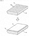
- board holding plate 24 has multiple suction holes 24a formed in the top surface thereof and suction-holds board S set on the top surface by using negative pressure supplied through suction holes 24a that is achieved by suction force from suction pump 29 (refer to fig. 5 ).
- Moving mechanism 28, in this embodiment although not shown in detail, is configured as a shuttle mechanism that shuttles board holding plate 24 by driving a timing belt attached to board holding plate 24 using a motor.
- Component supply device 30 in this embodiment, is configured as a wafer supply device that supplies a round wafer 34 that has been diced into a matrix of multiple chips (components P).
- component supply device 30 is not limited to an item that supplies wafers 34, it may be an item that supplies tape in which components are stored at a specified interval, or an item that supplies trays in which components are arranged.
- mounting head 50 is configured as a multiple nozzle head on which multiple suction nozzles 51 are arranged in a circumferential direction.
- Mounting head 50 is provided with R-axis actuator 52 for revolving the head, ⁇ -axis actuator 54 for rotating each suction nozzle 51, and Z-axis actuator that moves suction nozzle 51 in the Z-axis (up-down) direction.
- a suction opening of suction nozzle 51 is connected to a suction pump, which is not shown.
- Suction nozzle 51 picks up component P by negative pressure supplied to the suction opening from the suction pump.
- XY robot 40 is provided with pair of left-right X-axis guide rails 41 provided at an upper level along the front-rear direction (X-axis direction), X-axis slider 42 supported on the pair of left-right X-axis guide rails 41 so as to be movable along X-axis guide rails 41, Y-axis guide rails 43 provided on a side surface of X-axis slider 42 in a left-right direction (Y-axis direction), and Y-axis slider 44 provided to be movable along Y-axis guide rails 43.
- X-axis slider 42 is moved by the driving of X-axis actuator 46 (refer to fig.
- Y-axis slider 44 is moved by the driving of Y-axis actuator 48 (refer to fig. 5 ).
- Mounting head 50 is provided on Y-axis slider 44, and control device 70 moves mounting head 50 to any position in an XY plane by performing drive control of XY robot 40 (X-axis actuator 46 and Y-axis actuator 48).
- pressing device 60 is provided with holding stand 62 formed in approximately an L-shape such that horizontal section 62a at an upper surface is parallel with the XY plane (upper surface of base 12) when viewed from the side, pressing head 64 including a pressing surface (lower surface) for applying pressure to component P mounted on board S, and Z-axis actuator 66 provided on horizontal section 62a of support stand 62 that moves pressing head 64 in the Z-axis (vertical) direction.
- Pressing head 64 includes a pressing surface with a width that enables multiple components P mounted on board S to be pressed at once.
- pressing head 64 includes a rectangular pressing surface that covers the entire width in the Y-axis direction (direction perpendicular to board conveyance direction) of the mounting region of board S, and that is narrower in the X-axis direction.
- control device 70 is configured from CPU 71 that is based around a microprocessor, and is also provided with ROM 72, HDD 73, RAM 74, and input-output interface 75. These items are electrically connected by bus 76. Image signals from component camera 38, image signals from mark camera 58, and so on are inputted into control device 70 via input-output interface 75.
- control device 70 outputted from control device 70 via an output board are control signals to board conveyance 20, control signals to component supply device 30, drive signals to XY robot 40 (X-axis actuator 46 and Y-axis actuator 48), drive signals to mounting head 50 (R-axis actuator 52, ⁇ -axis actuator 54, and Z-axis actuator 56), drive signals to pressing device 60 (Z-axis actuator 66), drive signals to heater 26, and drive signals to suction pump 29.
- control device 70 is connected to management device 80 such that two-way communication is possible, and they perform communication of data and control signals with each other.
- Management device 80 for example, is a general purpose computer provided with items such as CPU 81, ROM 82, HDD 83, RAM 84, and input-output interface 85. These items are electrically connected by bus 86. Management device 80 receives input signals from input device 87 such as a mouse or a keyboard via input-output interface 85, and image signals are output from management device 80 to display 88 via input-output interface 85. HDD 93 memorizes a production plan of board S.
- the board production plan is a plan that defines which components should be mounted on the board and in what order by component mounter 10, along with how many boards S mounted with components P in this manner are to be manufactured, and so on.
- Management device 80 creates a production plan based on data (type of mounting head to be used, type and size of components P to be mounted, mounting positions of each component P, and so on) entered by an operator via input device 87, and sends the created production plan to component mounter 10.
- FIG. 6 and 7 are flowcharts showing an example of component mounting processing performed by control device 70. This processing is performed when mounting of component P has been indicated by management device 80 receiving an instruction signal.
- component mounting processing below, descriptions are given with reference to the mounting process and pressing process shown in figs. 8 and 9 .
- CPU 71 of control device 70 When component mounting processing is performed, CPU 71 of control device 70, first, performs drive control of suction pump 29 such that board S set on board holding plate 24 is suction-held (S100), and turns heater 26 on (S110). By this, board S is heated by heater 26 via board holding plate 24 in a state with the entire surface held by board holding plate 24. Therefore, it is possible to prevent temperature differences arising across the entire board, thus curtailing bending and warping of board S caused by temperature differences.
- the setting of board S on board holding plate 24 may be performed manually by an operator, or may be performed automatically using a board supply device, which is not shown.
- CPU 71 when heater 26 is turned on, performs drive control of moving mechanism 28 such that board S held by board holding plate 24 is conveyed to an initial position inside the machine (S120, refer to fig. 8[a] ), and initializes a value of 1 (sets region 1) for region N which is the current target region for mounting from all the mounting regions of board S (S130).
- an initial position is where region 1 is positioned in front in the X direction of a position directly above which is pressing head 64 (refer to fig. 8[b] ).
- Fig. 10 illustrates mounting regions of board S.
- the mounting regions of board S are divided into first to nth rectangular regions with the short side lined up in the X-axis direction (board conveyance direction), and the mounting process and pressing process is performed in each region.
- Each region is approximately the same as the region of the pressing surface of pressing head 64, and all the components P mounted inside one region can be pressed by pressing head 64 at once.
- CPU 71 performs drive control of XY robot 40 and mounting head 50 to apply negative pressure to suction nozzle 51 so as to pick up component P supplied by component supply device 30 using suction nozzle 51 (S140).
- CPU 71 performs drive control of XY robot 40 to move mounting head 50 above component camera 38, and uses component camera 38 to capture an image of component P (pickup component) held by suction nozzle 51, then processes the image to measure the pickup deviation of the pickup component, and sets a correction amount with respect the mounting position of the pickup component based on the measured pickup deviation amount (S150).
- CPU 71 based on the set correction amount and the mounting position of the pickup component specified in the production plan, performs drive control of XY robot 40 and mounting head 50 and performs mounting processing (mounting process) of mounting the pickup component at the mounting position inside region N of board S by applying positive pressure to suction nozzle 51 (S160, refer to fig. 8[c] ).
- CPU 71 upon performing mounting processing, determines whether mounting of components P in region N that is the current mounting target is complete (S170). In this embodiment, region N is wide enough for a single row of components P to be mounted in the Y-axis direction (direction perpendicular to the board conveyance direction).
- processing of S170 determines that mounting is complete when a single row of components P has been mounted in the Y-axis direction.
- CPU 71 if determining in S170 that mounting of components P in region N is not complete, repeats processing of S140 to S170.
- CPU 71 determines whether N is a value of 2 or greater (S180).
- N a value of 2 or greater
- CPU 71 determines in S180 that N is not 2 or greater, that is, that N is 1, and after performing drive control of moving mechanism 28 to move board S a specified amount such that region N in which components P were mounted is directly below pressing head 64 (S210, refer to fig. 9[d] ), performs pressing processing (pressing process) by performing drive control of pressing device 60 such that pressing head 64 is lowered until the upper surfaces of components P mounted inside region N are contacted by the pressing surface of pressing head 64 (S220). By this, pressure is applied to all components P mounted in region N (region 1) at once by pressing head 64.
- CPU 71 upon starting the pressing process, determines whether mounting of components P has been completed for all mounting regions of board S (S230). CPU 71, if determining that mounting of all components P is not complete, increments N by 1 (S240), and performs mounting processing (mounting process) of components with respect to the next mounting target region, region (N + 1) (S140 to S170). That is, CPU 71 performs mounting processing with respect to the next region (N + 1) while performing pressing processing with respect to region N. In this manner, by performing the pressing process and the mounting process in parallel, waiting time for each process is reduced, such that overall work time is reduced.
- CPU 71 after incrementing region N by 1 in S240 and performing mounting processing of S140 to S170, determines in S180 that N is 2 or greater, and waits for the pressing process (bonding of component P) being performed to complete (S190).
- processing of S190 is performed by determining whether a specified time (for example, 0.5 seconds) has elapsed since starting performing the pressing process in S220.
- CPU 71 if determining that the pressing process being performed has been completed, performs drive control of pressing device 60 to raise pressing head 64 such that pressing head 64 is separated from components P (S200), and in parallel moves board S a specified amount such that pressing head 64 is directly above the mounting target region (N + 1) of the mounting process that was being performed (S210), and then lowers pressing head 64 and starts performing pressing processing with respect to the components P mounted in the region (N + 1) (S220). In this manner, by moving board S a specified amount each time, the cycle of mounting processing and pressing processing is performed consecutively while shifting the target mounting region (refer to fig. 9[e] ).
- CPU 71 if determining in S230 that mounting of components P is complete for all mounting regions of board S, waits for the completion of the pressing process currently being performed (S250), and then performs drive control of pressing device 60 to raise pressing head 64 (S260). Then, CPU 71 performs drive control of moving mechanism 28 to convey board S out of the machine (S270, refer to fig. 9[f] ), turns off heater 26, and performs drive control of suction pump 29 such that holding of board S is released (S290), and ends component mounting processing.
- Board holding plate 24 of this embodiment corresponds to a "holding member" of the present invention
- heater 26 corresponds to a "heater”
- mounting head 50 corresponds to a “mounting head”
- pressing head 64 corresponds to a "pressing head”
- CPU 71 of control device 70 that performs component mounting processing of figs. 6 and 7 corresponds to a "control means”.
- moving mechanism 28 (shuttle mechanism) corresponds to a "feeding mechanism”.
- Component mounter 10 of the above-described embodiment is configured such that board S held by board holding plate 24 can be heated by heater 26, and after performing mounting processing of components P in region N of the mounting regions of board S, performs a pressing process of using pressing head 64 to apply pressure to all components P mounted in region N at once while heating board S, and to perform a next mounting process of mounting components P in a next region (N + 1) while performing the pressing process.
- pressing head 64 to apply pressure to all components P mounted in region N at once while heating board S, and to perform a next mounting process of mounting components P in a next region (N + 1) while performing the pressing process.
- heater 26 is provided on board holding plate 24, and the entire surface of board S is heated via board holding plate 24 while the entire surface of board S is held by board holding plate 24.
- the pressing surface of pressing head 64 is formed to cover the entire width in the Y-axis direction (direction perpendicular to the board conveyance direction) of the mounting region of board S, and the mounting process and the pressing process are performed in parallel while consecutively moving (conveying) boards S. This improves operating efficiency.
- pressing head 64 when performing the pressing process and the mounting process in parallel, after completing the mounting process with respect to region (N + 1), pressing head 64 is raised after waiting for the completion of the pressing process with respect to region N, but in a case in which the pressing process with respect to region N is completed before the mounting process with respect to region (N + 1) is complete, the pressing head may be raised when the pressing process with respect to region N is complete, without waiting for the mounting process to be completed.
- mounting (mounting process) and pressing (pressing process) of components P is performed by one row each in the Y-axis direction (direction perpendicular to the board conveyance direction), but the mounting process and the pressing process may be performed for two or more rows each.
- the width of the mounting target region and the size of pressing head 64 (pressing surface) may be decided based on the size of component P and the quantity of rows to be processed in one cycle (one mounting process and one pressing process).
- pressing head 64 is configured to be able to press the entire width in the Y-axis direction (direction perpendicular to the board conveyance direction) of the mounting region of board S in one go, but the size of the area that can be pressed in one go may be a narrower region than the entire width in the Y-axis direction.
- pressing head 64 may be movable in the Y-axis direction, and the mounting target region may be divided into multiple regions in the Y-axis direction of board S.
- the pressing process may be performed with respect to the target mounting region, and while the pressing process is being performed, the mounting process may be performed on a mounting target region that is a region shifted one in the Y-axis direction, with such a cycle being repeated.
- pressing head 64 is unable to move in the X-axis direction (board conveyance direction), and components P mounted on board S are pressed by the pressing region being shifted in order by conveying board S a specified distance in the X-axis direction each time; however, pressing head 64 may be movable in the X-axis direction, and components P mounted on board S may be pressed by the pressing region being shifted in order by pressing head 64 being moved with respect to board S a specified distance in the X-axis direction each time.
- the present invention may be applied to the industrial field of component mounters and the like.
Landscapes
- Engineering & Computer Science (AREA)
- Manufacturing & Machinery (AREA)
- Microelectronics & Electronic Packaging (AREA)
- Supply And Installment Of Electrical Components (AREA)
Abstract
Description
- The present invention relates to a component mounter.
- Conventionally, it is known, after mounting a component on a board, to secure the component to the board by applying pressure to the mounted component while heating the board or the component. For example, disclosed in
patent literature 1 is an electronic component manufacturing device provided with a bonding head that has a heater built into a pressing section, and a receiving stand; with the device, an external electrode section of a liquid crystal display body held on a holding table and a driver IC chip arranged on the external electrode section are sandwiched by the bonding head and the receiving table, and an input electrode of the external electrode section and an output electrode of the driver IC chip are bonded by pressure being applied while the driver IC chip is heated by the heater. - Patent literature 1:
JP-A-H11-67839 - However, with the above device, mounting of the component on the board and securing of the component are performed in different devices, so production efficiency is low. Also, if a temperature difference arises across the entire board when the board is heated, the board may warp easily, which may worsen board production yields.
- An object of the present invention is to improve production efficiency while curtailing occurrences of defect boards.
- The present invention uses the following means to achieve the above object.
- A component mounter of the present invention is a component mounter for mounting components on a board, the component mounter including:
- a holding member configured to hold the board at a holding surface;
- a heater configured to heat an entire surface of the board;
- a mounting head configured to mount the components on the board held by the holding member;
- a pressing head configured to apply pressure to the component mounted on the board at a specified region that is narrower than a mounting region of the board; and
- a control means configured to, after using the mounting head to perform a mounting process of mounting a component in the specified region within the mounting region of the board held by the holding member, use the pressing head to perform a pressing process of applying pressure to the component in the specified region mounted on the board while the heater heats the entire surface of the board, and use the mounting head to perform a next mounting process of mounting a component in the next specified region of the board while the pressing process is being performed.
- With a component mounter of the present invention, after using a mounting head to perform a mounting process of mounting a component in a specified region within a mounting region of a board, a pressing head is used to perform a pressing process of applying pressure to the component in the specified region mounted on the board while heating the entire surface of the board with a heater, and then the mounting head is used to perform a next mounting process of mounting a component in a next specified region of the board while the pressing process is being performed. In this manner, by performing the mounting process and the pressing process in parallel, it is possible to shorten the overall work time while maintaining sufficient time for the pressing process. Also, because the heater heats the entire surface of the board, bending and warping of the board is curtailed. As a result, it is possible to improve production efficiency while curtailing production of defective boards.
- In such a component mounter of the present invention, the heater may be provided on the holding member so as to be capable of heating the entire surface of the board via the holding surface. Thus, it is possible to effectively curtail the occurrence of bending or warping of the board while the board is being heated.
- Such a component mounter of the present invention may further include a feeding mechanism configured to feed the holding member in a specified direction, wherein the control means is configured to, after performing the mounting process, perform the pressing process after heating the board with the heater and feeding the holding member a specified amount using the feeding mechanism in a state with the holding member holding the board, and perform the next mounting process while performing the pressing process, such that the pressing process and the mounting process are performed repeatedly while shifting the specified region by the specified amount each time. Accordingly, it is possible to perform the mounting process and pressing process more efficiently.
- With such a component mounter of the present invention, the pressing head may be configured to apply pressure to the component at, as the specified region, a perpendicular region that is along a perpendicular direction that is perpendicular with respect to the feeding direction of the board, and the control means may be configured to, after performing the mounting process of mounting the component in the perpendicular region of the board using the mounting head, perform the pressing process after feeding the holding member the specified amount using the feeding mechanism, and use the mounting head to perform the next mounting process of mounting a component in the next perpendicular region while performing the pressing process.
-
- [
Fig. 1 ]
Fig. 1 shows an outline of the configuration of an embodiment,component mounting system 1. - [
Fig. 2 ]
Fig. 2 showsboard holding plate 24 holding board S. - [
Fig. 3 ]
Fig. 3 shows an outline of the configuration of mountinghead 50. - [
Fig. 4 ]
Fig. 4 shows pressingdevice 60 applying pressure to component P mounted on board S. - [
Fig. 5 ]
Fig. 5 is a block diagram showing electrical connections ofmanagement device 80 andcontrol device 70 ofcomponent mounter 10. - [
Fig. 6 ]
Fig. 6 is a flowchart showing an example (a first half) of component mounting processing performed by CPU 71 ofcontrol device 70. - [
Fig. 7 ]
Fig. 7 is a flowchart showing an example (a second half) of component mounting processing performed by CPU 71 ofcontrol device 70. - [
Fig. 8 ]
Fig. 8 shows a mounting process and a pressing process being performed. - [
Fig. 9 ]
Fig. 9 shows a mounting process and a pressing process being performed. - [
Fig. 10 ]
Fig. 10 illustrates mounting regions of board S. - An embodiment of the present invention is described below.
-
Fig. 1 shows an outline of the configuration of an embodiment,component mounting system 1;fig. 2 showsboard holding plate 24 holding board S;fig. 3 shows an outline of the configuration ofmounting head 50;fig. 4 shows pressingdevice 60 applying pressure to component P mounted on board S; andfig. 5 is a block diagram showing electrical connections ofmanagement device 80 andcontrol device 70 ofcomponent mounter 10. Note that, a front-rear (near side-far side) direction infig. 1 is an X-axis direction, a left-right direction is a Y-axis direction, and an up-down direction is a Z-axis direction. - As shown in
fig. 1 , an embodiment,component mounting 1, is provided with:component mounter 10 capable of performing a mounting process of mounting component P on board S via a thermosetting adhesive, and a pressing process of bonding the mounted component P to board S by applying pressure while heating board S; andmanagement device 80 that manages the overall system. - As shown in
fig. 1 ,component mounter 10 is provided withbase 12,board conveyance device 20 that conveys board S,component supply device 30 that supplies component P, mountinghead 50 for performing a mounting process,XY robot 40 for movingmounting head 50 in XY directions, pressingdevice 60 for performing a pressing process, andcontrol device 70 for performing control of devices overall. Note that,component mounter 10 is also provided with items such ascomponent camera 38 arranged onbase 12 for capturing an image of component P picked up (by suction) by mounting head 50 (suction nozzle 51), andmark camera 58 arranged on mountinghead 50 that is capable of imaging reference marks used for positioning provided on board S (refer tofig. 5 ). - As shown in
fig. 1 ,board conveyance device 20 is provided with: stand 22 including an upper surface roughly the same height as an upper surface ofbase 12;board holding plate 24 that holds the entire underside surface of board S on a top surface (holding surface);heater 26 arranged underboard holding plate 24 that heats the entire surface of board S held byboard holding plate 24 viaboard holding plate 24; andmoving mechanism 28 that movesboard holding plate 24 back and forth in the X-axis direction betweenstand 22 andbase 12. As shown infig. 2 ,board holding plate 24 hasmultiple suction holes 24a formed in the top surface thereof and suction-holds board S set on the top surface by using negative pressure supplied throughsuction holes 24a that is achieved by suction force from suction pump 29 (refer tofig. 5 ).Moving mechanism 28, in this embodiment, although not shown in detail, is configured as a shuttle mechanism that shuttlesboard holding plate 24 by driving a timing belt attached toboard holding plate 24 using a motor. -
Component supply device 30, in this embodiment, is configured as a wafer supply device that supplies around wafer 34 that has been diced into a matrix of multiple chips (components P). Note that,component supply device 30 is not limited to an item that supplies wafers 34, it may be an item that supplies tape in which components are stored at a specified interval, or an item that supplies trays in which components are arranged. - As shown in
fig. 3 , mountinghead 50 is configured as a multiple nozzle head on whichmultiple suction nozzles 51 are arranged in a circumferential direction.Mounting head 50 is provided with R-axis actuator 52 for revolving the head, θ-axis actuator 54 for rotating eachsuction nozzle 51, and Z-axis actuator that movessuction nozzle 51 in the Z-axis (up-down) direction. A suction opening ofsuction nozzle 51 is connected to a suction pump, which is not shown.Suction nozzle 51 picks up component P by negative pressure supplied to the suction opening from the suction pump. - As shown in
fig. 1 ,XY robot 40 is provided with pair of left-rightX-axis guide rails 41 provided at an upper level along the front-rear direction (X-axis direction),X-axis slider 42 supported on the pair of left-rightX-axis guide rails 41 so as to be movable alongX-axis guide rails 41, Y-axis guide rails 43 provided on a side surface ofX-axis slider 42 in a left-right direction (Y-axis direction), and Y-axis slider 44 provided to be movable along Y-axis guide rails 43. Note that,X-axis slider 42 is moved by the driving of X-axis actuator 46 (refer tofig. 5 ), and Y-axis slider 44 is moved by the driving of Y-axis actuator 48 (refer tofig. 5 ). Mountinghead 50 is provided on Y-axis slider 44, andcontrol device 70moves mounting head 50 to any position in an XY plane by performing drive control of XY robot 40 (X-axis actuator 46 and Y-axis actuator 48). - As shown in
fig. 4 , pressingdevice 60 is provided with holdingstand 62 formed in approximately an L-shape such thathorizontal section 62a at an upper surface is parallel with the XY plane (upper surface of base 12) when viewed from the side, pressinghead 64 including a pressing surface (lower surface) for applying pressure to component P mounted on board S, and Z-axis actuator 66 provided onhorizontal section 62a of support stand 62 that moves pressinghead 64 in the Z-axis (vertical) direction. Pressinghead 64 includes a pressing surface with a width that enables multiple components P mounted on board S to be pressed at once. In this embodiment, pressinghead 64 includes a rectangular pressing surface that covers the entire width in the Y-axis direction (direction perpendicular to board conveyance direction) of the mounting region of board S, and that is narrower in the X-axis direction. - As shown in
fig. 5 ,control device 70 is configured from CPU 71 that is based around a microprocessor, and is also provided with ROM 72, HDD 73,RAM 74, and input-output interface 75. These items are electrically connected bybus 76. Image signals fromcomponent camera 38, image signals frommark camera 58, and so on are inputted intocontrol device 70 via input-output interface 75. On the other hand, outputted fromcontrol device 70 via an output board are control signals toboard conveyance 20, control signals tocomponent supply device 30, drive signals to XY robot 40 (X-axis actuator 46 and Y-axis actuator 48), drive signals to mounting head 50 (R-axis actuator 52, θ-axis actuator 54, and Z-axis actuator 56), drive signals to pressing device 60 (Z-axis actuator 66), drive signals toheater 26, and drive signals tosuction pump 29. Also,control device 70 is connected tomanagement device 80 such that two-way communication is possible, and they perform communication of data and control signals with each other. -
Management device 80, for example, is a general purpose computer provided with items such asCPU 81,ROM 82,HDD 83,RAM 84, and input-output interface 85. These items are electrically connected bybus 86.Management device 80 receives input signals frominput device 87 such as a mouse or a keyboard via input-output interface 85, and image signals are output frommanagement device 80 to display 88 via input-output interface 85. HDD 93 memorizes a production plan of board S. Here, the board production plan is a plan that defines which components should be mounted on the board and in what order bycomponent mounter 10, along with how many boards S mounted with components P in this manner are to be manufactured, and so on.Management device 80 creates a production plan based on data (type of mounting head to be used, type and size of components P to be mounted, mounting positions of each component P, and so on) entered by an operator viainput device 87, and sends the created production plan tocomponent mounter 10. - Next, operation of the embodiment of
component mounter 10 configured as above is described.Fig. 6 and7 are flowcharts showing an example of component mounting processing performed bycontrol device 70. This processing is performed when mounting of component P has been indicated bymanagement device 80 receiving an instruction signal. With regard to component mounting processing, below, descriptions are given with reference to the mounting process and pressing process shown infigs. 8 and9 . - When component mounting processing is performed, CPU 71 of
control device 70, first, performs drive control ofsuction pump 29 such that board S set onboard holding plate 24 is suction-held (S100), and turnsheater 26 on (S110). By this, board S is heated byheater 26 viaboard holding plate 24 in a state with the entire surface held byboard holding plate 24. Therefore, it is possible to prevent temperature differences arising across the entire board, thus curtailing bending and warping of board S caused by temperature differences. Note that, the setting of board S onboard holding plate 24 may be performed manually by an operator, or may be performed automatically using a board supply device, which is not shown. - CPU 71, when
heater 26 is turned on, performs drive control of movingmechanism 28 such that board S held byboard holding plate 24 is conveyed to an initial position inside the machine (S120, refer tofig. 8[a] ), and initializes a value of 1 (sets region 1) for region N which is the current target region for mounting from all the mounting regions of board S (S130). Here, in this embodiment, an initial position is whereregion 1 is positioned in front in the X direction of a position directly above which is pressing head 64 (refer tofig. 8[b] ).Fig. 10 illustrates mounting regions of board S. As shown, the mounting regions of board S are divided into first to nth rectangular regions with the short side lined up in the X-axis direction (board conveyance direction), and the mounting process and pressing process is performed in each region. Each region is approximately the same as the region of the pressing surface of pressinghead 64, and all the components P mounted inside one region can be pressed by pressinghead 64 at once. - Next, CPU 71 performs drive control of
XY robot 40 and mountinghead 50 to apply negative pressure tosuction nozzle 51 so as to pick up component P supplied bycomponent supply device 30 using suction nozzle 51 (S140). Continuing, CPU 71 performs drive control ofXY robot 40 to move mountinghead 50 abovecomponent camera 38, and usescomponent camera 38 to capture an image of component P (pickup component) held bysuction nozzle 51, then processes the image to measure the pickup deviation of the pickup component, and sets a correction amount with respect the mounting position of the pickup component based on the measured pickup deviation amount (S150). Then, CPU 71, based on the set correction amount and the mounting position of the pickup component specified in the production plan, performs drive control ofXY robot 40 and mountinghead 50 and performs mounting processing (mounting process) of mounting the pickup component at the mounting position inside region N of board S by applying positive pressure to suction nozzle 51 (S160, refer tofig. 8[c] ). CPU 71, upon performing mounting processing, determines whether mounting of components P in region N that is the current mounting target is complete (S170). In this embodiment, region N is wide enough for a single row of components P to be mounted in the Y-axis direction (direction perpendicular to the board conveyance direction). Accordingly, processing of S170 determines that mounting is complete when a single row of components P has been mounted in the Y-axis direction. CPU 71, if determining in S170 that mounting of components P in region N is not complete, repeats processing of S140 to S170. - On the other hand, CPU 71, if determining that mounting of components P in region N is complete, determines whether N is a value of 2 or greater (S180). Here, assuming that components P have been mounted in
region 1, CPU 71 determines in S180 that N is not 2 or greater, that is, that N is 1, and after performing drive control of movingmechanism 28 to move board S a specified amount such that region N in which components P were mounted is directly below pressing head 64 (S210, refer tofig. 9[d] ), performs pressing processing (pressing process) by performing drive control of pressingdevice 60 such that pressinghead 64 is lowered until the upper surfaces of components P mounted inside region N are contacted by the pressing surface of pressing head 64 (S220). By this, pressure is applied to all components P mounted in region N (region 1) at once by pressinghead 64. - CPU 71, upon starting the pressing process, determines whether mounting of components P has been completed for all mounting regions of board S (S230). CPU 71, if determining that mounting of all components P is not complete, increments N by 1 (S240), and performs mounting processing (mounting process) of components with respect to the next mounting target region, region (N + 1) (S140 to S170). That is, CPU 71 performs mounting processing with respect to the next region (N + 1) while performing pressing processing with respect to region N. In this manner, by performing the pressing process and the mounting process in parallel, waiting time for each process is reduced, such that overall work time is reduced.
- CPU 71, after incrementing region N by 1 in S240 and performing mounting processing of S140 to S170, determines in S180 that N is 2 or greater, and waits for the pressing process (bonding of component P) being performed to complete (S190). Here, in this embodiment, processing of S190 is performed by determining whether a specified time (for example, 0.5 seconds) has elapsed since starting performing the pressing process in S220. CPU 71, if determining that the pressing process being performed has been completed, performs drive control of pressing
device 60 to raisepressing head 64 such that pressinghead 64 is separated from components P (S200), and in parallel moves board S a specified amount such that pressinghead 64 is directly above the mounting target region (N + 1) of the mounting process that was being performed (S210), and then lowers pressinghead 64 and starts performing pressing processing with respect to the components P mounted in the region (N + 1) (S220). In this manner, by moving board S a specified amount each time, the cycle of mounting processing and pressing processing is performed consecutively while shifting the target mounting region (refer tofig. 9[e] ). - CPU 71, if determining in S230 that mounting of components P is complete for all mounting regions of board S, waits for the completion of the pressing process currently being performed (S250), and then performs drive control of pressing
device 60 to raise pressing head 64 (S260). Then, CPU 71 performs drive control of movingmechanism 28 to convey board S out of the machine (S270, refer tofig. 9[f] ), turns offheater 26, and performs drive control ofsuction pump 29 such that holding of board S is released (S290), and ends component mounting processing. - Correspondences between constituent elements of the present embodiment and constituent elements of the invention will be clarified here.
Board holding plate 24 of this embodiment corresponds to a "holding member" of the present invention,heater 26 corresponds to a "heater", mountinghead 50 corresponds to a "mounting head", pressinghead 64 corresponds to a "pressing head", and CPU 71 ofcontrol device 70 that performs component mounting processing offigs. 6 and7 corresponds to a "control means". Also, moving mechanism 28 (shuttle mechanism) corresponds to a "feeding mechanism". -
Component mounter 10 of the above-described embodiment is configured such that board S held byboard holding plate 24 can be heated byheater 26, and after performing mounting processing of components P in region N of the mounting regions of board S, performs a pressing process of usingpressing head 64 to apply pressure to all components P mounted in region N at once while heating board S, and to perform a next mounting process of mounting components P in a next region (N + 1) while performing the pressing process. In this manner, by performing the pressing process and the mounting process in parallel, waiting time for each process in the cycle of the mounting process and the pressing process is reduced, such that overall work time is reduced. - Also, with
component mounter 10 of this embodiment,heater 26 is provided onboard holding plate 24, and the entire surface of board S is heated viaboard holding plate 24 while the entire surface of board S is held byboard holding plate 24. By this, it is possible to reduce temperature differences across the entire board, thus curtailing bending and warping of board S caused by temperature differences. - Also, with
component mounter 10 of this embodiment, the pressing surface of pressinghead 64 is formed to cover the entire width in the Y-axis direction (direction perpendicular to the board conveyance direction) of the mounting region of board S, and the mounting process and the pressing process are performed in parallel while consecutively moving (conveying) boards S. This improves operating efficiency. - Meanwhile, it goes without saying that the invention is not limited to the above-mentioned embodiment and various embodiments may be applied within the technical scope of the invention.
- For example, in an embodiment above, when performing the pressing process and the mounting process in parallel, after completing the mounting process with respect to region (N + 1), pressing
head 64 is raised after waiting for the completion of the pressing process with respect to region N, but in a case in which the pressing process with respect to region N is completed before the mounting process with respect to region (N + 1) is complete, the pressing head may be raised when the pressing process with respect to region N is complete, without waiting for the mounting process to be completed. - Also, with an embodiment above, mounting (mounting process) and pressing (pressing process) of components P is performed by one row each in the Y-axis direction (direction perpendicular to the board conveyance direction), but the mounting process and the pressing process may be performed for two or more rows each. In this case, the width of the mounting target region and the size of pressing head 64 (pressing surface) may be decided based on the size of component P and the quantity of rows to be processed in one cycle (one mounting process and one pressing process).
- Also, in an embodiment above, pressing
head 64 is configured to be able to press the entire width in the Y-axis direction (direction perpendicular to the board conveyance direction) of the mounting region of board S in one go, but the size of the area that can be pressed in one go may be a narrower region than the entire width in the Y-axis direction. In this case, pressinghead 64 may be movable in the Y-axis direction, and the mounting target region may be divided into multiple regions in the Y-axis direction of board S. Further, after performing mounting processing with respect to one mounting target region out of the multiple regions and completing the mounting process, the pressing process may be performed with respect to the target mounting region, and while the pressing process is being performed, the mounting process may be performed on a mounting target region that is a region shifted one in the Y-axis direction, with such a cycle being repeated. - Also, in an embodiment above, pressing
head 64 is unable to move in the X-axis direction (board conveyance direction), and components P mounted on board S are pressed by the pressing region being shifted in order by conveying board S a specified distance in the X-axis direction each time; however, pressinghead 64 may be movable in the X-axis direction, and components P mounted on board S may be pressed by the pressing region being shifted in order by pressinghead 64 being moved with respect to board S a specified distance in the X-axis direction each time. - The present invention may be applied to the industrial field of component mounters and the like.
- 1: component mounting system; 10: component mounter; 12: base; 20: board conveyance device; 22: stand; 24: board holding plate; 24a: suction hole; 26: heater; 28: moving mechanism; 29: suction pump; 30: component supply device; 32: stand; 34: wafer; 38: component camera; 40: XY robot; 41: X-axis guide rail; 42: X-axis slider; 43: Y-axis guide rail; 44: Y-axis slider; 46: X-axis actuator; 48: Y-axis actuator; 50: mounting head; 51: suction nozzle; 52: R-axis actuator; 54: θ-axis actuator; 56: Z-axis actuator; 58: mark camera; 60: pressing device; 62: holding stand; 62a: horizontal section; 64: pressing head; 66: Z-axis actuator; 70: control device; 71: CPU; 72: ROM; 73: HDD; 74: RAM; 75: input-output interface; 76: bus; 80: management device; 81: CPU; 82: ROM; 83: HDD; 84: RAM; 85: input-output interface; 86: bus; 87: input device; 88: display; S: board; P: component
Claims (4)
- A component mounter for mounting components on a board, the component mounter comprising:a holding member configured to hold the board at a holding surface;a heater configured to heat an entire surface of the board;a mounting head configured to mount the components on the board held by the holding member;a pressing head configured to apply pressure to the component mounted on the board at a specified region that is narrower than a mounting region of the board; anda control means configured to, after using the mounting head to perform a mounting process of mounting a component in the specified region within the mounting region of the board held by the holding member, use the pressing head to perform a pressing process of applying pressure to the component in the specified region mounted on the board while the heater heats the entire surface of the board, and use the mounting head to perform a next mounting process of mounting a component in the next specified region of the board while the pressing process is being performed.
- The component mounter according to claim 1, wherein
the heater is provided on the holding member so as to be capable of heating the entire surface of the board via the holding surface. - The component mounter according to claim 2, further comprising:
a feeding mechanism configured to feed the holding member in a specified direction,
wherein
the control means is configured to, after performing the mounting process, perform the pressing process after heating the board with the heater and feeding the holding member a specified amount using the feeding mechanism in a state with the holding member holding the board, and perform the next mounting process while performing the pressing process, such that the pressing process and the mounting process are performed repeatedly while shifting the specified region by the specified amount each time. - The component mounter according to claim 3, wherein
the pressing head is configured to apply pressure to the component at, as the specified region, a perpendicular region that is along a perpendicular direction that is perpendicular with respect to the feeding direction of the board, and
the control means is configured to, after performing the mounting process of mounting the component in the perpendicular region of the board using the mounting head, perform the pressing process after feeding the holding member the specified amount using the feeding mechanism, and use the mounting head to perform the next mounting process of mounting a component in the next perpendicular region while performing the pressing process.
Applications Claiming Priority (1)
| Application Number | Priority Date | Filing Date | Title |
|---|---|---|---|
| PCT/JP2015/067211 WO2016203532A1 (en) | 2015-06-15 | 2015-06-15 | Component mounting machine |
Publications (3)
| Publication Number | Publication Date |
|---|---|
| EP3310147A1 true EP3310147A1 (en) | 2018-04-18 |
| EP3310147A4 EP3310147A4 (en) | 2018-05-23 |
| EP3310147B1 EP3310147B1 (en) | 2019-09-11 |
Family
ID=57545476
Family Applications (1)
| Application Number | Title | Priority Date | Filing Date |
|---|---|---|---|
| EP15895553.4A Active EP3310147B1 (en) | 2015-06-15 | 2015-06-15 | Component mounting machine |
Country Status (4)
| Country | Link |
|---|---|
| US (1) | US10285317B2 (en) |
| EP (1) | EP3310147B1 (en) |
| JP (1) | JP6499286B2 (en) |
| WO (1) | WO2016203532A1 (en) |
Families Citing this family (2)
| Publication number | Priority date | Publication date | Assignee | Title |
|---|---|---|---|---|
| US11991832B2 (en) * | 2018-05-28 | 2024-05-21 | Fuji Corporation | Unit exchanging device |
| CN112789959B (en) * | 2018-10-02 | 2022-08-19 | 株式会社富士 | Working machine |
Family Cites Families (15)
| Publication number | Priority date | Publication date | Assignee | Title |
|---|---|---|---|---|
| JPS5515270A (en) * | 1978-07-19 | 1980-02-02 | Matsushita Electric Industrial Co Ltd | Method of attaching electronic part |
| JPS62203339A (en) * | 1986-03-04 | 1987-09-08 | Matsushita Electric Ind Co Ltd | Bonding of part |
| JPH0629349A (en) | 1992-07-10 | 1994-02-04 | Matsushita Electric Ind Co Ltd | Semiconductor element mounting method |
| JP3102241B2 (en) * | 1993-12-24 | 2000-10-23 | 松下電器産業株式会社 | Electronic component bonding apparatus and bonding method |
| JP2830852B2 (en) * | 1996-08-08 | 1998-12-02 | 松下電器産業株式会社 | Electronic component mounting method |
| JP3442615B2 (en) * | 1997-05-29 | 2003-09-02 | 松下電器産業株式会社 | Substrate heating method |
| JP3617270B2 (en) | 1997-08-22 | 2005-02-02 | セイコーエプソン株式会社 | Electronic device manufacturing method and electronic device manufacturing apparatus |
| JP2001118149A (en) | 1999-10-19 | 2001-04-27 | Toshiba Tec Corp | Product sales data processing device |
| JP4068844B2 (en) * | 1999-11-29 | 2008-03-26 | 芝浦メカトロニクス株式会社 | Component mounting apparatus and component mounting method |
| JP2002118149A (en) * | 2000-10-05 | 2002-04-19 | Hitachi Ltd | Semiconductor device manufacturing method and semiconductor manufacturing apparatus |
| US8528196B2 (en) * | 2009-01-08 | 2013-09-10 | Panasonic Corporation | Component mounting apparatus and method |
| JP2011199184A (en) * | 2010-03-23 | 2011-10-06 | Fujifilm Corp | Substrate mounting device and substrate mounting method |
| KR102037948B1 (en) * | 2012-12-28 | 2019-10-29 | 세메스 주식회사 | Die bonding method and apparatus |
| KR102232636B1 (en) * | 2013-03-28 | 2021-03-25 | 토레이 엔지니어링 컴퍼니, 리미티드 | Mounting method and mounting device |
| WO2016031806A1 (en) * | 2014-08-25 | 2016-03-03 | 東レエンジニアリング株式会社 | Mounting head and mounting device in which same is used |
-
2015
- 2015-06-15 US US15/736,622 patent/US10285317B2/en active Active
- 2015-06-15 WO PCT/JP2015/067211 patent/WO2016203532A1/en not_active Ceased
- 2015-06-15 EP EP15895553.4A patent/EP3310147B1/en active Active
- 2015-06-15 JP JP2017524168A patent/JP6499286B2/en active Active
Also Published As
| Publication number | Publication date |
|---|---|
| WO2016203532A1 (en) | 2016-12-22 |
| US10285317B2 (en) | 2019-05-07 |
| US20180192554A1 (en) | 2018-07-05 |
| JPWO2016203532A1 (en) | 2018-03-29 |
| EP3310147A4 (en) | 2018-05-23 |
| EP3310147B1 (en) | 2019-09-11 |
| JP6499286B2 (en) | 2019-04-10 |
Similar Documents
| Publication | Publication Date | Title |
|---|---|---|
| JP6823103B2 (en) | Mounting method and mounting device | |
| KR102156690B1 (en) | Electronic component mounting device and mounting method, and method for manufacturing package component | |
| KR102080214B1 (en) | Mounting apparatus and mounting method of an electronic component, and the manufacturing method of a package part | |
| US10569351B2 (en) | Soldering device | |
| US10784130B2 (en) | Bonding apparatus | |
| JP6717630B2 (en) | Electronic component mounting equipment | |
| EP3310147B1 (en) | Component mounting machine | |
| US9780514B2 (en) | Component mounting method | |
| EP3171685B1 (en) | Component mounting device | |
| JP5690791B2 (en) | Substrate processing equipment | |
| KR101381559B1 (en) | Method and apparatus for ball grid array rework | |
| EP3315903B1 (en) | Board inspection apparatus | |
| JP6942829B2 (en) | Electronic component mounting device | |
| EP3585141A1 (en) | Component mounting system and component mounting method | |
| JP2540954B2 (en) | Bonding method and apparatus | |
| JP2004047927A (en) | Electronic component mounting equipment | |
| JP2015133357A (en) | Surface mounter, component supplier, and positional deviation detection method | |
| JP7664534B2 (en) | Component crimping device and component crimping method | |
| KR102747594B1 (en) | Substrate processing system, apparatus for aligning substrate unit, method of processing substrate | |
| JP7410826B2 (en) | Pin misalignment measuring device and die feeding device | |
| US20230413502A1 (en) | Component mounter and clamp control method | |
| KR101541332B1 (en) | Apparatus for mounting PCB on JIG | |
| JP6714730B2 (en) | Working machine and soldering method | |
| WO2016056045A1 (en) | Substrate working machine and mounting method |
Legal Events
| Date | Code | Title | Description |
|---|---|---|---|
| STAA | Information on the status of an ep patent application or granted ep patent |
Free format text: STATUS: THE INTERNATIONAL PUBLICATION HAS BEEN MADE |
|
| PUAI | Public reference made under article 153(3) epc to a published international application that has entered the european phase |
Free format text: ORIGINAL CODE: 0009012 |
|
| STAA | Information on the status of an ep patent application or granted ep patent |
Free format text: STATUS: REQUEST FOR EXAMINATION WAS MADE |
|
| 17P | Request for examination filed |
Effective date: 20171208 |
|
| AK | Designated contracting states |
Kind code of ref document: A1 Designated state(s): AL AT BE BG CH CY CZ DE DK EE ES FI FR GB GR HR HU IE IS IT LI LT LU LV MC MK MT NL NO PL PT RO RS SE SI SK SM TR |
|
| AX | Request for extension of the european patent |
Extension state: BA ME |
|
| A4 | Supplementary search report drawn up and despatched |
Effective date: 20180419 |
|
| RIC1 | Information provided on ipc code assigned before grant |
Ipc: H05K 13/04 20060101AFI20180413BHEP |
|
| DAV | Request for validation of the european patent (deleted) | ||
| DAX | Request for extension of the european patent (deleted) | ||
| RAP1 | Party data changed (applicant data changed or rights of an application transferred) |
Owner name: FUJI CORPORATION |
|
| RIN1 | Information on inventor provided before grant (corrected) |
Inventor name: YAMASAKI, TOSHIHIKO Inventor name: SHIMIZU, TOSHINORI Inventor name: MURAI, MASAKI |
|
| GRAP | Despatch of communication of intention to grant a patent |
Free format text: ORIGINAL CODE: EPIDOSNIGR1 |
|
| STAA | Information on the status of an ep patent application or granted ep patent |
Free format text: STATUS: GRANT OF PATENT IS INTENDED |
|
| INTG | Intention to grant announced |
Effective date: 20190522 |
|
| GRAS | Grant fee paid |
Free format text: ORIGINAL CODE: EPIDOSNIGR3 |
|
| GRAA | (expected) grant |
Free format text: ORIGINAL CODE: 0009210 |
|
| STAA | Information on the status of an ep patent application or granted ep patent |
Free format text: STATUS: THE PATENT HAS BEEN GRANTED |
|
| AK | Designated contracting states |
Kind code of ref document: B1 Designated state(s): AL AT BE BG CH CY CZ DE DK EE ES FI FR GB GR HR HU IE IS IT LI LT LU LV MC MK MT NL NO PL PT RO RS SE SI SK SM TR |
|
| REG | Reference to a national code |
Ref country code: GB Ref legal event code: FG4D |
|
| REG | Reference to a national code |
Ref country code: CH Ref legal event code: EP |
|
| REG | Reference to a national code |
Ref country code: AT Ref legal event code: REF Ref document number: 1180215 Country of ref document: AT Kind code of ref document: T Effective date: 20190915 |
|
| REG | Reference to a national code |
Ref country code: DE Ref legal event code: R096 Ref document number: 602015038051 Country of ref document: DE Ref country code: IE Ref legal event code: FG4D |
|
| REG | Reference to a national code |
Ref country code: NL Ref legal event code: MP Effective date: 20190911 |
|
| REG | Reference to a national code |
Ref country code: LT Ref legal event code: MG4D |
|
| PG25 | Lapsed in a contracting state [announced via postgrant information from national office to epo] |
Ref country code: FI Free format text: LAPSE BECAUSE OF FAILURE TO SUBMIT A TRANSLATION OF THE DESCRIPTION OR TO PAY THE FEE WITHIN THE PRESCRIBED TIME-LIMIT Effective date: 20190911 Ref country code: HR Free format text: LAPSE BECAUSE OF FAILURE TO SUBMIT A TRANSLATION OF THE DESCRIPTION OR TO PAY THE FEE WITHIN THE PRESCRIBED TIME-LIMIT Effective date: 20190911 Ref country code: BG Free format text: LAPSE BECAUSE OF FAILURE TO SUBMIT A TRANSLATION OF THE DESCRIPTION OR TO PAY THE FEE WITHIN THE PRESCRIBED TIME-LIMIT Effective date: 20191211 Ref country code: SE Free format text: LAPSE BECAUSE OF FAILURE TO SUBMIT A TRANSLATION OF THE DESCRIPTION OR TO PAY THE FEE WITHIN THE PRESCRIBED TIME-LIMIT Effective date: 20190911 Ref country code: NO Free format text: LAPSE BECAUSE OF FAILURE TO SUBMIT A TRANSLATION OF THE DESCRIPTION OR TO PAY THE FEE WITHIN THE PRESCRIBED TIME-LIMIT Effective date: 20191211 Ref country code: LT Free format text: LAPSE BECAUSE OF FAILURE TO SUBMIT A TRANSLATION OF THE DESCRIPTION OR TO PAY THE FEE WITHIN THE PRESCRIBED TIME-LIMIT Effective date: 20190911 |
|
| PG25 | Lapsed in a contracting state [announced via postgrant information from national office to epo] |
Ref country code: LV Free format text: LAPSE BECAUSE OF FAILURE TO SUBMIT A TRANSLATION OF THE DESCRIPTION OR TO PAY THE FEE WITHIN THE PRESCRIBED TIME-LIMIT Effective date: 20190911 Ref country code: GR Free format text: LAPSE BECAUSE OF FAILURE TO SUBMIT A TRANSLATION OF THE DESCRIPTION OR TO PAY THE FEE WITHIN THE PRESCRIBED TIME-LIMIT Effective date: 20191212 Ref country code: ES Free format text: LAPSE BECAUSE OF FAILURE TO SUBMIT A TRANSLATION OF THE DESCRIPTION OR TO PAY THE FEE WITHIN THE PRESCRIBED TIME-LIMIT Effective date: 20190911 Ref country code: AL Free format text: LAPSE BECAUSE OF FAILURE TO SUBMIT A TRANSLATION OF THE DESCRIPTION OR TO PAY THE FEE WITHIN THE PRESCRIBED TIME-LIMIT Effective date: 20190911 Ref country code: RS Free format text: LAPSE BECAUSE OF FAILURE TO SUBMIT A TRANSLATION OF THE DESCRIPTION OR TO PAY THE FEE WITHIN THE PRESCRIBED TIME-LIMIT Effective date: 20190911 |
|
| REG | Reference to a national code |
Ref country code: AT Ref legal event code: MK05 Ref document number: 1180215 Country of ref document: AT Kind code of ref document: T Effective date: 20190911 |
|
| PG25 | Lapsed in a contracting state [announced via postgrant information from national office to epo] |
Ref country code: EE Free format text: LAPSE BECAUSE OF FAILURE TO SUBMIT A TRANSLATION OF THE DESCRIPTION OR TO PAY THE FEE WITHIN THE PRESCRIBED TIME-LIMIT Effective date: 20190911 Ref country code: RO Free format text: LAPSE BECAUSE OF FAILURE TO SUBMIT A TRANSLATION OF THE DESCRIPTION OR TO PAY THE FEE WITHIN THE PRESCRIBED TIME-LIMIT Effective date: 20190911 Ref country code: NL Free format text: LAPSE BECAUSE OF FAILURE TO SUBMIT A TRANSLATION OF THE DESCRIPTION OR TO PAY THE FEE WITHIN THE PRESCRIBED TIME-LIMIT Effective date: 20190911 Ref country code: PL Free format text: LAPSE BECAUSE OF FAILURE TO SUBMIT A TRANSLATION OF THE DESCRIPTION OR TO PAY THE FEE WITHIN THE PRESCRIBED TIME-LIMIT Effective date: 20190911 Ref country code: PT Free format text: LAPSE BECAUSE OF FAILURE TO SUBMIT A TRANSLATION OF THE DESCRIPTION OR TO PAY THE FEE WITHIN THE PRESCRIBED TIME-LIMIT Effective date: 20200113 Ref country code: AT Free format text: LAPSE BECAUSE OF FAILURE TO SUBMIT A TRANSLATION OF THE DESCRIPTION OR TO PAY THE FEE WITHIN THE PRESCRIBED TIME-LIMIT Effective date: 20190911 Ref country code: IT Free format text: LAPSE BECAUSE OF FAILURE TO SUBMIT A TRANSLATION OF THE DESCRIPTION OR TO PAY THE FEE WITHIN THE PRESCRIBED TIME-LIMIT Effective date: 20190911 |
|
| PG25 | Lapsed in a contracting state [announced via postgrant information from national office to epo] |
Ref country code: SK Free format text: LAPSE BECAUSE OF FAILURE TO SUBMIT A TRANSLATION OF THE DESCRIPTION OR TO PAY THE FEE WITHIN THE PRESCRIBED TIME-LIMIT Effective date: 20190911 Ref country code: CZ Free format text: LAPSE BECAUSE OF FAILURE TO SUBMIT A TRANSLATION OF THE DESCRIPTION OR TO PAY THE FEE WITHIN THE PRESCRIBED TIME-LIMIT Effective date: 20190911 Ref country code: SM Free format text: LAPSE BECAUSE OF FAILURE TO SUBMIT A TRANSLATION OF THE DESCRIPTION OR TO PAY THE FEE WITHIN THE PRESCRIBED TIME-LIMIT Effective date: 20190911 Ref country code: IS Free format text: LAPSE BECAUSE OF FAILURE TO SUBMIT A TRANSLATION OF THE DESCRIPTION OR TO PAY THE FEE WITHIN THE PRESCRIBED TIME-LIMIT Effective date: 20200224 |
|
| REG | Reference to a national code |
Ref country code: DE Ref legal event code: R097 Ref document number: 602015038051 Country of ref document: DE |
|
| PLBE | No opposition filed within time limit |
Free format text: ORIGINAL CODE: 0009261 |
|
| STAA | Information on the status of an ep patent application or granted ep patent |
Free format text: STATUS: NO OPPOSITION FILED WITHIN TIME LIMIT |
|
| PG2D | Information on lapse in contracting state deleted |
Ref country code: IS |
|
| PG25 | Lapsed in a contracting state [announced via postgrant information from national office to epo] |
Ref country code: DK Free format text: LAPSE BECAUSE OF FAILURE TO SUBMIT A TRANSLATION OF THE DESCRIPTION OR TO PAY THE FEE WITHIN THE PRESCRIBED TIME-LIMIT Effective date: 20190911 Ref country code: IS Free format text: LAPSE BECAUSE OF FAILURE TO SUBMIT A TRANSLATION OF THE DESCRIPTION OR TO PAY THE FEE WITHIN THE PRESCRIBED TIME-LIMIT Effective date: 20200112 |
|
| 26N | No opposition filed |
Effective date: 20200615 |
|
| PG25 | Lapsed in a contracting state [announced via postgrant information from national office to epo] |
Ref country code: SI Free format text: LAPSE BECAUSE OF FAILURE TO SUBMIT A TRANSLATION OF THE DESCRIPTION OR TO PAY THE FEE WITHIN THE PRESCRIBED TIME-LIMIT Effective date: 20190911 |
|
| PG25 | Lapsed in a contracting state [announced via postgrant information from national office to epo] |
Ref country code: MC Free format text: LAPSE BECAUSE OF FAILURE TO SUBMIT A TRANSLATION OF THE DESCRIPTION OR TO PAY THE FEE WITHIN THE PRESCRIBED TIME-LIMIT Effective date: 20190911 |
|
| REG | Reference to a national code |
Ref country code: CH Ref legal event code: PL |
|
| GBPC | Gb: european patent ceased through non-payment of renewal fee |
Effective date: 20200615 |
|
| PG25 | Lapsed in a contracting state [announced via postgrant information from national office to epo] |
Ref country code: LU Free format text: LAPSE BECAUSE OF NON-PAYMENT OF DUE FEES Effective date: 20200615 |
|
| REG | Reference to a national code |
Ref country code: BE Ref legal event code: MM Effective date: 20200630 |
|
| PG25 | Lapsed in a contracting state [announced via postgrant information from national office to epo] |
Ref country code: FR Free format text: LAPSE BECAUSE OF NON-PAYMENT OF DUE FEES Effective date: 20200630 Ref country code: IE Free format text: LAPSE BECAUSE OF NON-PAYMENT OF DUE FEES Effective date: 20200615 Ref country code: GB Free format text: LAPSE BECAUSE OF NON-PAYMENT OF DUE FEES Effective date: 20200615 Ref country code: CH Free format text: LAPSE BECAUSE OF NON-PAYMENT OF DUE FEES Effective date: 20200630 Ref country code: LI Free format text: LAPSE BECAUSE OF NON-PAYMENT OF DUE FEES Effective date: 20200630 |
|
| PG25 | Lapsed in a contracting state [announced via postgrant information from national office to epo] |
Ref country code: BE Free format text: LAPSE BECAUSE OF NON-PAYMENT OF DUE FEES Effective date: 20200630 |
|
| PG25 | Lapsed in a contracting state [announced via postgrant information from national office to epo] |
Ref country code: TR Free format text: LAPSE BECAUSE OF FAILURE TO SUBMIT A TRANSLATION OF THE DESCRIPTION OR TO PAY THE FEE WITHIN THE PRESCRIBED TIME-LIMIT Effective date: 20190911 Ref country code: MT Free format text: LAPSE BECAUSE OF FAILURE TO SUBMIT A TRANSLATION OF THE DESCRIPTION OR TO PAY THE FEE WITHIN THE PRESCRIBED TIME-LIMIT Effective date: 20190911 Ref country code: CY Free format text: LAPSE BECAUSE OF FAILURE TO SUBMIT A TRANSLATION OF THE DESCRIPTION OR TO PAY THE FEE WITHIN THE PRESCRIBED TIME-LIMIT Effective date: 20190911 |
|
| PG25 | Lapsed in a contracting state [announced via postgrant information from national office to epo] |
Ref country code: MK Free format text: LAPSE BECAUSE OF FAILURE TO SUBMIT A TRANSLATION OF THE DESCRIPTION OR TO PAY THE FEE WITHIN THE PRESCRIBED TIME-LIMIT Effective date: 20190911 |
|
| P01 | Opt-out of the competence of the unified patent court (upc) registered |
Effective date: 20230328 |
|
| PGFP | Annual fee paid to national office [announced via postgrant information from national office to epo] |
Ref country code: DE Payment date: 20250429 Year of fee payment: 11 |