EP3308619A1 - Streugerät zum verteilen von streugut - Google Patents
Streugerät zum verteilen von streugut Download PDFInfo
- Publication number
- EP3308619A1 EP3308619A1 EP17401107.2A EP17401107A EP3308619A1 EP 3308619 A1 EP3308619 A1 EP 3308619A1 EP 17401107 A EP17401107 A EP 17401107A EP 3308619 A1 EP3308619 A1 EP 3308619A1
- Authority
- EP
- European Patent Office
- Prior art keywords
- drive shaft
- spreader
- agitator
- lens
- overload clutch
- Prior art date
- Legal status (The legal status is an assumption and is not a legal conclusion. Google has not performed a legal analysis and makes no representation as to the accuracy of the status listed.)
- Granted
Links
Images


Classifications
-
- A—HUMAN NECESSITIES
- A01—AGRICULTURE; FORESTRY; ANIMAL HUSBANDRY; HUNTING; TRAPPING; FISHING
- A01C—PLANTING; SOWING; FERTILISING
- A01C15/00—Fertiliser distributors
- A01C15/005—Undercarriages, tanks, hoppers, stirrers specially adapted for seeders or fertiliser distributors
- A01C15/006—Hoppers
- A01C15/007—Hoppers with agitators in the hopper
-
- A—HUMAN NECESSITIES
- A01—AGRICULTURE; FORESTRY; ANIMAL HUSBANDRY; HUNTING; TRAPPING; FISHING
- A01C—PLANTING; SOWING; FERTILISING
- A01C17/00—Fertilisers or seeders with centrifugal wheels
- A01C17/005—Driving mechanisms for the throwing devices
-
- A—HUMAN NECESSITIES
- A01—AGRICULTURE; FORESTRY; ANIMAL HUSBANDRY; HUNTING; TRAPPING; FISHING
- A01C—PLANTING; SOWING; FERTILISING
- A01C19/00—Arrangements for driving working parts of fertilisers or seeders
Definitions
- the invention relates to a spreader for distributing grit according to the preamble of claim 1.
- Spreaders usually have a reservoir for the grit, within which a stirrer is arranged.
- the agitator should avoid blockages in the region of the outlet opening of the reservoir, as well as to ensure a uniform outflow of the material to be spread or to promote.
- the storage container leaving through the outlet opening diffuser falls in generic devices on a rotating disc driven, which then ejects the grit.
- the document discloses DE 36 37 045 C2 a fertilizer spreader, in which the lens is rotationally driven by a drive means and the agitator is freely rotatably mounted without an active drive.
- the object underlying the invention is therefore to provide a spreader in which the speed and torque conversion between the lens spreading drive shaft and the Rhackorganantriebswelle is implemented to save space and the mechanics used can be performed easily and inexpensively.
- the object is achieved by a spreader of the type mentioned, wherein the Rhackorganantriebswelle and the lens drive shaft are interconnected via an eccentric gear.
- the invention makes use of the knowledge that eccentric gears allow extremely high transmission and / or reduction ratios in a compact design.
- the compact design of the gearbox allows the picking point of the Place the grits close to the diffuser center, which protects the grit when it is picked up by the diffuser.
- the transmission components are sometimes considerably less stressed in eccentric gearboxes than in helical or bevel gearboxes. The reduced stress significantly increases the service life and the reliability.
- the stirring element is arranged in the funnel tip of the reservoir.
- the agitator drive shaft and the lens drive shaft each extend in the vertical direction.
- the drive torque of the drive device is introduced into the lens drive shaft and transmitted via the eccentric to the Rhackorganantriebswelle.
- One or more torque-transmitting intermediate shafts may each be arranged between the diffuser drive shaft and the eccentric gear and / or between the eccentric gear and the agitator drive shaft.
- the eccentric is formed as a reduction gear.
- the agitator drive shaft can be arranged completely or in sections in a housing, wherein the agitator and the housing cover separately or in one piece, i. can be formed as integral components of a component.
- the spreader according to the invention is further developed advantageous in that the eccentric gear is designed as a gear-free gear.
- a gear-free eccentric gear is preferred in which a cam is used.
- Cams, other than gears, are not stressed by shearing forces, so that the life and reliability are further increased.
- the eccentric gear is designed as a cycloidal gear.
- the lens spreading drive shaft is designed as a transmission input shaft and the agitator drive shaft as a transmission output shaft.
- the transmission input shaft preferably has an eccentric portion which drives a cam. Between the eccentric portion and the cam, a rolling bearing is preferably arranged.
- the cam preferably has a plurality of curve sections, which roll in a fixed cam ring. In particular, the number of curved sections of the cam ring is higher than the number of curved sections of the cam disc.
- the cam ring has one, two, three or four curve sections more than the cam plate.
- the cam preferably has a plurality of through holes arranged on a circular path.
- a pin extends through the through-holes, wherein the through-holes have a larger diameter than the pins.
- the pins are connected to the transmission output shaft or part of the shaft. Through the pins, the transmission output shaft is driven by the cam, wherein the tumbling rotary motion of the cam is transformed by the arrangement and dimensioning of the through holes of the cam and the pins in a uniform rotational movement of the transmission output shaft.
- the agitator drive shaft and the spreader disc drive shaft are arranged parallel or coaxial with each other.
- the parallel or coaxial arrangement of the agitator drive shaft and the lens drive shaft reduces system complexity.
- the tumbling rotary motion of the cam of the cycloid gear can be introduced into the agitator without deformation.
- the Stirring efficiency of the stirring element is further increased by the tumbling rotary motion.
- the agitator drive shaft and the spreader disc drive shaft have opposite directions of rotation.
- the opposite rotational directions of the Roaneorganantriebswelle and the lens drive shaft can be opposite rotational directions of the stirring member and the lens to implement.
- an overload clutch is arranged between the agitator and the lens drive shaft.
- a blockage of the stirring element can be caused, for example, by objects which have inadvertently entered the storage container for the spreading material.
- strong clumping of the grit can lead to a blockage of the stirrer.
- the spreader is protected from damage by the overload clutch, reducing the risk of failure and increasing the life of the spreader.
- the overload coupling considerably reduces the risk of injury to the machine operator.
- a spreader in which the overload clutch is arranged between the agitator and the agitator drive shaft.
- the overload clutch is further arranged between the agitator and the lens drive shaft, characterized in this embodiment, the lens drive shaft and the eccentric gear is protected from overload and thus from damage. There is thus a further reduction in the risk of damage caused by overloading the spreader. Time-consuming and costly repair work on the eccentric gear or replacement of the eccentric gear can be avoided in this way.
- the overload clutch is arranged between the lens drive shaft and the eccentric gear or between the eccentric gear and the agitator drive shaft.
- different types of coupling can be used because the speed and torque level before the eccentric gear greatly different from the speed and torque level behind the eccentric gear.
- the arrangement of the overload clutch between the lens drive shaft and the eccentric gear is suitable for coupling types, which interrupt the torque transmission at comparatively low torque limits.
- the arrangement of the overload coupling between the eccentric gear and the agitator drive shaft is suitable for coupling types which interrupt torque transmission at comparatively high limit torques. The low speed on the output side is advantageous in terms of wear when touching couplings.
- the overload clutch is integrated in the eccentric gear.
- the overload clutch is disposed within the housing of the eccentric gear.
- the drive train can be made even more compact and space-saving by integrating the overload clutch in the eccentric gear.
- the maintenance is simplified and accelerated because the number of functional components to be serviced is reduced by the integration of the overload clutch in the eccentric gear.
- the stirring element takes over the task of overload protection, or elastically preformable stirring elements or fingers are used.
- a spreader according to the invention in which the overload clutch is designed as a self-actuating torque-switching safety clutch is preferred.
- the overload clutch automatically interrupts the torque transmission when a limit torque is exceeded and provides the Torque transmission when falling below the limit torque automatically restored.
- the limit torque of the overload clutch is preferably selected such that damage to individual components of the drive train prior to the interruption of the torque transmission by the overload clutch is excluded or at least extremely unlikely.
- an overload clutch with a comparatively low limit torque or an overload clutch with a comparatively high torque limit can be selected. If an overload clutch is selected with a comparatively low torque limit, the components of the powertrain may have a lower strength and thus be manufactured more cost-effectively.
- the stirring power of the stirring element is restricted. If an overload clutch with a comparatively high limit torque is selected, the agitator can provide a high stirring power. At the same time, however, the components of the transmission must have a certain strength, whereby the manufacturing costs are increased.
- the overload clutch is designed as a slip clutch or as a blocking body clutch.
- the overload clutch may comprise one or more spring-loaded pressure elements, which are deflected when a limit torque is exceeded, wherein the deflection of the one or more spring-loaded pressure elements has an interruption of torque transmission result ,
- the one or more spring-loaded pressure elements can be arranged depending on the arrangement of the overload clutch in front of the eccentric gear or behind the eccentric gear or integrated in the eccentric gear.
- the one or more spring-loaded pressure elements can also be arranged in the cycloidal disk of the cycloidal drive.
- the overload clutch causes an axial displacement of the Rownorganantriebswelle and / or a threshold torque is exceeded Stroke movement of the stirrer.
- the overload clutch causes an axial displacement of the stirrer drive shaft and / or a stroke of the stirrer in the opposite direction at the falling below the limit torque below the limit torque.
- the axial displacement of the stirrer drive shaft and / or the lifting movement of the stirrer in the opposite direction can be carried out directly at the undershooting of the limit torque or only after reaching a certain angle of rotation of the Rownorganantriebswelle.
- the Fig. 1 shows a spreader 10 for distributing grit with a reservoir 12 for the grit.
- the storage container 12 has a funnel 14, in which a stirrer 16 is arranged.
- the stirring member 16 is of a Rhackorganantriebswelle 50, which is covered by a designed as a housing cover 18 mixing head, rotatably driven.
- the rotational movement is transmitted from the Rntonorganantriebswelle 50 to the housing cover 18, wherein the housing cover 18 transmits the rotational movement of the stirring fingers 20a-20d.
- a housing 22a, 22b is arranged, wherein the housing parts 22a, 22b are connected to each other with fastening elements 24a, 24d.
- the fastening elements 24a, 24d are each designed as a screw-nut combination.
- a multi-part diffuser drive shaft 26 is arranged in sections within the housing part 22b and connected via a within the housing 22a, 22b arranged eccentric (hidden) with the Rntonorganantriebswelle 50.
- the lens drive shaft 26 is adapted to drive a lens rotating, wherein the lens dispenses the storage container 12 leaving the grit.
- the Fig. 2 shows that the housing cover 18 is secured by means of a Sich ceremoniesssplints 28.
- the stirring element 16 has a total of six evenly arranged over the circumference of the stirring member 16 and obliquely upwardly angled stirring fingers 20a-20f, wherein the support plate of the stirring fingers 20a-20f is connected to the housing cover 18 via a plurality of fasteners 66 formed as rivets.
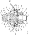
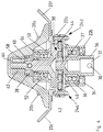
- the Fig. 3 and the Fig. 4 show that the lens drive shaft 26 has a through hole 30 and a hollow bore 32. Through the hollow bore 32 and the through hole 30, the illustrated part of Lens drive shaft 26 are connected to other parts of the lens drive shaft 26 using a locking pin.
- the lens drive shaft 26 is sealed relative to the housing part 22b by means of a seal 34 designed as a radial shaft seal. Between the diffuser drive shaft 26 and the housing part 22b designed as a double-row deep groove ball bearings 36 is arranged.
- the agitator drive shaft 50 and the lens drive shaft 26 each extend in the vertical direction and are arranged coaxially with each other.
- the torque introduced by the common drive device into the lens drive shaft 26 is transmitted to the agitator drive shaft 50 via the eccentric gear 38.
- the eccentric gear 38 is a reduction gear and as a gear-free transmission, namely as a cycloidal gear formed.
- the lens drive shaft 26 is formed as a transmission input shaft and the agitator drive shaft 50 is formed as a transmission output shaft.
- the lens drive shaft 26 has an eccentric portion 27 which drives a cam 42. Between the eccentric portion 27 of the lens drive shaft 26 and the cam 42, a roller bearing 40 is arranged.
- the cam 42 has a plurality of curve sections, which roll in a fixed cam ring 44 of the housing part 22b.
- the cam 42 has a plurality of circular holes arranged through holes 46a-46e, of which only the through hole 46a is shown. Each pin 48a-48e extends through the through-holes 46a-46e, with the through-holes 46a-46e having a larger diameter than the pins 48a-48e.
- the pins 48a-48e are connected to the agitator drive shaft 50. Via the pins 48a-48e, the agitator drive shaft 50 is driven by the cam 42, wherein the tumbling rotational movement of the cam 42 by the arrangement and dimensioning of the through holes 46a-46e of the cam 42 and the pins 48a-48e in a uniform, coaxial Rotational movement of the stirrer drive shaft 50 is formed.
- the eccentric gear 38 designed as a cycloidal gear mechanism
- the agitator drive shaft 50 and the lens drive shaft 26 have opposite directions of rotation.
- the agitator drive shaft 50 is sealed relative to the housing part 22a by means of a seal 54 designed as a radial shaft sealing ring.
- an overload clutch 56 is arranged between the agitator 16 and the lens drive shaft 26, namely between the agitator 16 and the Rhackorganantriebswelle 50.
- the overload clutch 56 is designed as an automatic torque-switching blocking body clutch and has a pin 58, wherein above the pin 58 designed as a claw pressure element 60 is arranged.
- the pressure element 60 transmits the rotational movement of the agitator drive shaft 50 to the housing cover 18, which transmits the rotational movement further to the agitator fingers 20a-20f.
- the pressure element 60 is deflected, wherein the deflection has an interruption of the torque transmission result. Due to the deflection of the pressure element 60, the overload coupling 56 causes a stroke movement of the stirring element 16 when the limit torque is exceeded.
- the pressure element 60 is acted upon by the spring element 62 with a restoring force, which counteracts the deflection.
- the spring element 62 is supported on the lock washer 64.
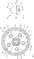
- the Fig. 5 shows parts of the eccentric gear formed as a cycloidal gear 38.
- the eccentric 27 of the lens drive shaft 26 extends through a through hole 70 of the cam 42.
- a rolling bearing 40 is further arranged, wherein the outer ring of the rolling bearing 40 bears against the cam 42 and the inner ring of the rolling bearing 40 on the eccentric portion 27 of the lens drive shaft 26.
- the cam 42 has a total of 15 outer curve sections, which roll in a total of 16 curve sections of a fixed cam ring 44.
- the cam 42 also has five arranged in a circular path through holes 46a-46e. Through each of the through holes 46a-46e, a pin 48a-48e extends. The pins 48a-48e are also arranged in a circular path. The through holes 46a-46e of the cam 42 have a larger diameter than the pins 48a-48e. The pins 48a-48e are connected to the agitator drive shaft 50 so that the agitator drive shaft 50 is driven by the cam 42 through the pins 48a-48e.
- the cam 42 performs due to the drive through the eccentric portion 27 of the lens drive shaft 26 a tumbling rotary motion.
- the tumbling rotational motion of the cam 42 is converted into a uniform, coaxial rotational movement of the agitator drive shaft 50 by the arrangement and dimensioning of the through holes 46a-46e of the cam 42 and the pins 48a-48e.
- the Fig. 6 shows portions of an overload clutch 56.
- the overload clutch 56 has a pin 58 which extends through a corresponding through hole in the Rownorganantriebswelle 50.
- the portions of the pin 58 arranged laterally of the agitator drive shaft 50 are in contact with a cam track 72 of a pressure element 60.
- the pressure element 60 has a central through hole (hidden) for the agitator drive shaft 50.
- the pressure element 60 transmits the rotational movement of the agitator drive shaft 50 to the housing cover 18, which transmits the rotational movement further to the agitator fingers 20a-20f.
- the pressure element 60 has two opposite recesses 68 a, 68 b, which for receiving a Backup splints 28 are established.
- the securing pin 28 extends through through holes in the housing cover 18 (see Fig. 2 ).
- the pressure element 60 is acted upon by the elastomer spring designed as a spring element 62 with a restoring force, which counteracts the deflection.
- the spring element 62 is supported on the lock washer 64. If the limit torque falls below again in the following, the restoring force of the spring element 62 brings the pressure element 60 and the pin 58 back into engagement after half a revolution of the pressure element 60, causing a stroke movement of the stirring element 16 in the opposite direction and the torque transmission is restored.
Landscapes
- Life Sciences & Earth Sciences (AREA)
- Soil Sciences (AREA)
- Environmental Sciences (AREA)
- Mixers Of The Rotary Stirring Type (AREA)
Abstract
Description
- Die Erfindung betrifft ein Streugerät zum Verteilen von Streugut gemäß dem Oberbegriff des Patentanspruches 1.
- Streugeräte weisen üblicherweise einen Vorratsbehälter für das Streugut auf, innerhalb welchem ein Rührorgan angeordnet ist. Das Rührorgan soll Verstopfungen in dem Bereich der Auslauföffnung des Vorratsbehälters vermeiden, sowie einen geleichmäßigen Ausfluss des Streugutes zu gewährleisten bzw. zu fördern.
- Das den Vorratsbehälter durch die Auslauföffnung verlassende Streugut fällt bei gattungsgemäßen Geräten auf eine rotierend angetriebene Streuscheibe, welche das Streugut dann auswirft.
- Diesbezüglich offenbart die Druckschrift
DE 36 37 045 C2 einen Düngerstreuer, bei welchem die Streuscheibe rotatorisch von einer Antriebseinrichtung angetrieben wird und das Rührwerk ohne einen aktiven Antrieb frei rotierbar gelagert ist. - Andere Ansätze sehen das aktive Antreiben der Streuscheibe und des Rührorgans vor. Die Druckschrift
EP 1 559 305 B1 schlägt hierzu einen Zweischeibenstreuer zum Verteilen von Streugut vor, wobei die Wurfscheiben und die Rührwerke von unterschiedlichen Antriebssträngen angetrieben werden. - Zur Reduzierung der Teileanzahl und zur Verringerung der Systemkomplexität ist man dazu übergegangen die Rührorganantriebswelle und die Streuscheibenantriebswelle mittels derselben Antriebseinrichtung anzutreiben.
- Aus der Druckschrift
DE 35 41 415 A1 ist beispielsweise ein Gerät zum Ausstreuen von pulverigem, körnigem und/oder kleinstückigem Streugut bekannt, deren Antriebswelle zwei unterschiedlich bemessene Kegelantriebsräder aufweist, wobei ein Kegelantriebsrad mit einem die Rührorganantriebswelle antreibenden Kegelabtriebsrad kämmt und ein Kegelantriebsrad mit einem die Streuscheibenantriebswelle antreibenden Kegelabtriebsrad kämmt. - Ferner offenbaren die Druckschriften
DE 33 37 813 A1 undDE 28 04 253 A1 weitere Lösungen, bei welchen die Streuscheibenantriebswelle und die Rührorganantriebswelle mittels eines Getriebes miteinander verbunden sind. - Einige bekannte Lösungen berücksichtigen bereits, dass zur Erzielung einer optimalen Streugutverteilung und zur Vermeidung einer Streugutbeschädigung die Streuscheibe und das Rührorgan unterschiedliche Drehzahlen und Drehmomente aufweisen müssen. Zur Wandlung der Drehzahl und des Drehmoments zwischen der Streuscheibenantriebswelle und der Rührorganantriebswelle werden üblicherweise Untersetzungsgetriebe eingesetzt.
- Die im Stand der Technik verwendeten Getriebearten benötigen jedoch einen großen Bauraum, um die gewünschten Übersetzungsverhältnisse umsetzen zu können. Ferner führt die Momentenübertragung bei den verwendeten Getriebearten zu einer hohen mechanischen Beanspruchung der Getriebekomponenten.
- Die der Erfindung zugrunde liegende Aufgabe besteht somit darin, ein Streugerät bereitzustellen, bei welchem die Drehzahl- und Momentenwandlung zwischen der Streuscheibenantriebswelle und der Rührorganantriebswelle platzsparend umgesetzt ist und die verwendete Mechanik einfach und kostengünstig ausgeführt werden kann.
- Die Aufgabe wird gelöst durch ein Streugerät der eingangs genannten Art, wobei die Rührorganantriebswelle und die Streuscheibenantriebswelle über ein Exzentergetriebe miteinander verbunden sind.
- Die Erfindung macht sich die Erkenntnis zunutze, dass Exzentergetriebe äußerst hohe Über- und/oder Untersetzungsverhältnisse bei kompakter Bauform ermöglichen. Die kompakte Bauform des Getriebes erlaubt den Aufgabepunkt des Streuguts nah am Streuscheibenmittelpunkt zu platzieren, wodurch das Streugut bei der Aufnahme durch die Streuscheibe geschont wird. Darüber hinaus lässt sich durch die geringe Baugröße ein Vorratsbehälter mit einer Trichterspitze gestalten, in welcher wenig Reststreugut zurückbleibt. Außerdem werden die Getriebekomponenten bei Exzentergetrieben teilweise erheblich weniger beansprucht als bei Stirnrad- oder Kegelradgetrieben. Durch die verringerte Beanspruchung werden die Lebensdauer und die Ausfallsicherheit erheblich erhöht.
- In einer bevorzugten Ausführungsform des erfindungsgemäßen Streugeräts ist das Rührorgan in der Trichterspitze des Vorratsbehälters angeordnet. Vorzugsweise verlaufen die Rührorganantriebswelle und die Streuscheibenantriebswelle jeweils in vertikaler Richtung. Insbesondere wird das Antriebsmoment der Antriebseinrichtung in die Streuscheibenantriebswelle eingeleitet und über das Exzentergetriebe an die Rührorganantriebswelle übertragen. Zwischen der Streuscheibenantriebswelle und dem Exzentergetriebe und/oder zwischen dem Exzentergetriebe und der Rührorganantriebswelle können jeweils ein oder mehrere drehmomentübertragende Zwischenwellen angeordnet sein. Um die Drehzahl der Rührorganantriebswelle gegenüber der Drehzahl der Streuscheibenantriebswelle zu reduzieren, ist es außerdem bevorzugt, dass das Exzentergetriebe als Untersetzungsgetriebe ausgebildet ist. Die Rührorganantriebswelle kann vollständig oder abschnittsweise in einem Gehäuse angeordnet sein, wobei das Rührorgan und der Gehäusedeckel separat oder einstückig, d.h. als integrale Bestandteile eines Bauteils ausgebildet sein können.
- Das erfindungsgemäße Streugerät wird ferner dadurch vorteilhaft weitergebildet, dass das Exzentergetriebe als zahnradfreies Getriebe ausgebildet ist. Insbesondere ist ein zahnradfreies Exzentergetriebe bevorzugt, bei welchem eine Kurvenscheibe Verwendung findet. Kurvenscheiben werden, anderes als Zahnräder, nicht durch Scherkräfte beansprucht, sodass die Lebensdauer und die Ausfallsicherheit weiter gesteigert werden.
- In einer besonders bevorzugten Ausführungsform des erfindungsgemäßen Streugeräts ist das Exzentergetriebe als Zykloidgetriebe ausgebildet. Vorzugsweise ist die Streuscheibenantriebswelle als Getriebeeingangswelle und die Rührorganantriebswelle als Getriebeausgangswelle ausgebildet. Die Getriebeeingangswelle weist vorzugsweise einen Exzenterabschnitt auf, welcher eine Kurvenscheibe antreibt. Zwischen dem Exzenterabschnitt und der Kurvenscheibe ist vorzugsweise ein Wälzlager angeordnet. Die Kurvenscheibe weist vorzugsweise mehrere Kurvenabschnitte auf, welche sich in einem feststehenden Kurvenring abwälzen. Insbesondere ist die Anzahl der Kurvenabschnitte des Kurvenrings höher als die Anzahl der Kurvenabschnitte der Kurvenscheibe. Vorzugsweise weist der Kurvenring ein, zwei, drei oder vier Kurvenabschnitte mehr als die Kurvenscheibe auf. Die Kurvenscheibe weist vorzugsweise mehrere auf einer Kreisbahn angeordnete Durchgangslöcher auf. Durch die Durchgangslöcher erstreckt sich jeweils ein Stift, wobei die Durchgangslöcher einen größeren Durchmesser als die Stifte aufweisen. Die Stifte sind mit der Getriebeausgangswelle verbunden oder Bestandteil der Welle. Über die Stifte wird die Getriebeausgangswelle durch die Kurvenscheibe angetrieben, wobei die taumelnde Drehbewegung der Kurvenscheibe durch die Anordnung und die Dimensionierung der Durchgangslöcher der Kurvenscheibe und der Stifte in eine gleichförmige Rotationsbewegung der Getriebeausgangswelle umgeformt wird.
- In einer weiteren Ausführungsfrom des erfindungsgemäßen Streugeräts sind die Rührorganantriebswelle und die Streuscheibenantriebswelle parallel oder koaxial zueinander angeordnet. Durch die parallele oder koaxiale Anordnung der Rührorganantriebswelle und der Streuscheibenantriebswelle wird die Systemkomplexität reduziert. Insbesondere lässt sich auf diese Weise die Lagerung der Rührorganantriebswelle und der Streuscheibenantriebswelle sowie die Geometrie des Gehäuses, in welchem die Rührorganantriebswelle und/oder die Streuscheibenantriebswelle angeordnet sind, erheblich vereinfachen. Alternativ kann die taumelnde Drehbewegung der Kurvenscheibe des Zykloidgetriebes ohne Umformung in das Rührorgan eingeleitet werden. Die Rühreffektivität des Rührorgans wird durch die taumelnde Drehbewegung nochmals gesteigert.
- In einer anderen Ausführungsform des erfindungsgemäßen Streugeräts weisen die Rührorganantriebswelle und die Streuscheibenantriebswelle entgegengesetzte Rotationsrichtungen auf. Durch die entgegengesetzten Rotationsrichtungen der Rührorganantriebswelle und der Streuscheibenantriebswelle lassen sich entgegengesetzte Rotationsrichtungen des Rührorgans und der Streuscheibe umsetzen.
- In einer besonders vorteilhaften Weiterbildung des erfindungsgemäßen Streugeräts ist zwischen dem Rührorgan und der Streuscheibenantriebswelle eine Überlastkupplung angeordnet. Auf diese Weise kann vermieden werden, dass eine Blockade der Rührorgans zu einem Stillstand der Streuscheibe führt. Eine Blockade des Rührorgans kann beispielsweise durch Gegenstände hervorgerufen werden, welche unbeabsichtigt in den Vorratsbehälter für das Streugut gelangt sind. Ferner können starke Verklumpungen des Streuguts zu einer Blockade des Rührorgans führen. Außerdem wird das Streugerät durch die Überlastkupplung vor Beschädigungen geschützt, sodass das Ausfallrisiko verringert und die Lebensdauer des Streugeräts erhöht wird. Darüber hinaus wird durch die Überlastkupplung das Verletzungsrisiko für den Maschinenbediener erheblich gesenkt.
- Bevorzugt ist ferner ein erfindungsgemäßes Streugerät, bei welchem die Überlastkupplung zwischen dem Rührorgan und der Rührorganantriebswelle angeordnet ist. Somit ist die Überlastkupplung weiterhin zwischen dem Rührorgan und der Streuscheibenantriebswelle angeordnet, dadurch wird in dieser Ausführungsform die Streuscheibenantriebswelle und das Exzentergetriebe vor Überlast und somit vor Beschädigungen geschützt. Es kommt somit zu einer weiteren Absenkung des Risikos einer durch Überlast hervorgerufenen Beschädigung des Streugeräts. Zeit- und kostenaufwändige Reparaturarbeiten an dem Exzentergetriebe oder ein Austausch des Exzentergetriebes können auf diese Weise vermieden werden.
- In einer anderen Ausführungsform des erfindungsgemäßen Streugeräts ist die Überlastkupplung zwischen der Streuscheibenantriebswelle und dem Exzentergetriebe oder zwischen dem Exzentergetriebe und der Rührorganantriebswelle angeordnet. Durch die Platzierung der Überlastkupplung vor oder hinter dem Exzentergetriebe können unterschiedliche Kupplungstypen verwendet werden, da sich das Drehzahl- und Momentenniveau vor dem Exzentergetriebe stark von dem Drehzahl- und Momentenniveau hinter dem Exzentergetriebe unterscheidet. Die Anordnung der Überlastkupplung zwischen der Streuscheibenantriebswelle und dem Exzentergetriebe eignet sich für Kupplungstypen, welche bei vergleichsweise geringen Grenzdrehmomenten die Momentenübertragung unterbrechen. Die Anordnung der Überlastkupplung zwischen dem Exzentergetriebe und der Rührorganantriebswelle eignet sich für Kupplungstypen, welche bei vergleichsweise hohen Grenzdrehmomenten die Momentenübertragung unterbrechen. Die niedrige Drehzahl auf Abtriebsseite ist bei berührenden Kupplungen aus verschleißtechnischer Sicht vorteilhaft.
- In einer weiteren bevorzugten Ausführungsform des erfindungsgemäßen Streugeräts ist die Überlastkupplung in dem Exzentergetriebe integriert. Vorzugsweise ist die Überlastkupplung innerhalb des Gehäuses des Exzentergetriebes angeordnet. Der Antriebsstrang kann durch die Integrierung der Überlastkupplung in dem Exzentergetriebe noch kompakter und platzsparender ausgeführt werden. Bei einer entsprechenden Konzipierung des Exzentergetriebes wird außerdem die Wartung vereinfacht und beschleunigt, da die zu wartende Anzahl von Funktionskomponenten durch die Integrierung der Überlastkupplung in dem Exzentergetriebe verringert wird. Es ist auch denkbar, dass das Rührorgan die Aufgab der Überlastsicherung übernimmt, oder elastisch vorformbare Rührelemente oder -finger eingesetzt werden.
- Bevorzugt ist darüber hinaus ein erfindungsgemäßes Streugerät, bei welchem die Überlastkupplung als selbsttätig drehmomentschaltende Sicherheitskupplung ausgebildet ist. Vorzugsweise unterbricht die Überlastkupplung bei Überschreitung eines Grenzdrehmoments selbsttätig die Momentenübertragung und stellt die Momentenübertragung bei Unterschreitung des Grenzdrehmoments selbsttätig wieder her. Das Grenzdrehmoment der Überlastkupplung wird vorzugsweise derart ausgewählt, dass eine Beschädigung einzelner Komponenten des Antriebsstrangs vor der Unterbrechung der Momentenübertragung durch die Überlastkupplung ausgeschlossen oder zumindest äußerst unwahrscheinlich ist. Somit kann, je nach Einsatzzweck, entweder eine Überlastkupplung mit einem vergleichsweise niedrigen Grenzdrehmoment oder eine Überlastkupplung mit einem vergleichsweise hohen Grenzdrehmoment ausgewählt werden. Wird eine Überlastkupplung mit einem vergleichsweise niedrigen Grenzdrehmoment ausgewählt, können die Komponenten des Antriebsstrangs eine geringere Festigkeit ausweisen und somit kostengünstiger hergestellt werden. Gleichzeitig wird jedoch die Rührleistung des Rührorgans eingeschränkt. Wird eine Überlastkupplung mit einem vergleichsweise hohen Grenzdrehmoment ausgewählt, kann das Rührorgan eine hohe Rührleistung erbringen. Gleichzeitig müssen die Komponenten des Getriebes jedoch eine gewisse Festigkeit aufweisen, wodurch die Herstellungskosten erhöht werden.
- In einer Weiterbildung des erfindungsgemäßen Streugeräts ist die Überlastkupplung als Rutschkupplung oder als Sperrkörperkupplung ausgebildet Die Überlastkupplung kann ein oder mehrere federkraftbeaufschlagte Druckelemente umfassen, welche bei Überschreitung eines Grenzdrehmoments ausgelenkt werden, wobei die Auslenkung des einen oder der mehreren federkraftbeaufschlagten Druckelemente eine Unterbrechung der Momentenübertragung zur Folge hat. Das eine oder die mehreren federkraftbeaufschlagten Druckelemente können abhängig von der Anordnung der Überlastkupplung vor dem Exzentergetriebe oder hinter dem Exzentergetriebe angeordnet oder in dem Exzentergetriebe integriert sein. Das eine oder die mehreren federkraftbeaufschlagten Druckelemente können auch in der Zykloidscheibe des Zykloidgetriebes angeordnet sein.
- In einer weiteren Ausführungsform des erfindungsgemäßen Streugeräts verursacht die Überlastkupplung beim Überschreiten eines Grenzdrehmoments eine axiale Verschiebung der Rührorganantriebswelle und/oder eine Hubbewegung des Rührorgans. Vorzugsweise verursacht die Überlastkupplung bei dem auf die Überschreitung des Grenzdrehmoments folgenden Unterschreiten des Grenzdrehmoments eine axiale Verschiebung der Rührorganantriebswelle und/oder eine Hubbewegung des Rührorgans in die entgegengesetzte Richtung. Die axiale Verschiebung der Rührorganantriebswelle und/oder die Hubbewegung des Rührorgans in die entgegengesetzte Richtung können dabei unmittelbar bei der Unterschreitung des Grenzdrehmoments oder erst nach Erreichen eines bestimmten Drehwinkels der Rührorganantriebswelle erfolgen.
- Weitere Einzelheiten der Erfindung sind der Figurenbeschreibung und den Zeichnungen zu entnehmen. Es zeigen
- Fig. 1
- ein Ausführungsbeispiel des erfindungsgemäßen Streugeräts in einer schematischen Darstellung;
- Fig. 2
- das Rührorgan des erfindungsgemäßen Streugeräts aus der
Fig. 1 in einer perspektivischen Darstellung; - Fig. 3
- das Rührorgan des erfindungsgemäßen Streugeräts aus der
Fig. 1 in einer Schnittdarstellung; - Fig. 4
- das Rührorgan des erfindungsgemäßen Streugeräts aus der
Fig. 1 in einer weiteren Schnittdarstellung; - Fig. 5
- Teile eines Zykloidgetriebes eines erfindungsgemäßen Streugeräts in einer schematischen Darstellung; und
- Fig. 6
- Teile einer Überlastkupplung eines erfindungsgemäßen Streugeräts in einer schematischen Darstellung.
- Die
Fig. 1 zeigt ein Streugerät 10 zum Verteilen von Streugut mit einem Vorratsbehälter 12 für das Streugut. Der Vorratsbehälter 12 weist einen Trichter 14 auf, in welchem ein Rührorgan 16 angeordnet ist. Das Rührorgan 16 wird von einer Rührorganantriebswelle 50, welche von einem als Gehäusedeckel 18 ausgebildeten Rührkopf verdeckt wird, rotatorisch angetrieben. - Die Rotationsbewegung wird von der Rührorganantriebswelle 50 an den Gehäusedeckel 18 übertragen, wobei der Gehäusedeckel 18 die Rotationsbewegung an die Rührfinger 20a-20d überträgt. Unterhalb des Gehäusedeckels 18 und der Rührfinger 20a-20d ist ein Gehäuse 22a, 22b angeordnet, wobei die Gehäuseteile 22a, 22b mit Befestigungselementen 24a, 24d miteinander verbunden sind. Die Befestigungselemente 24a, 24d sind jeweils als Schrauben-Mutter-Kombination ausgeführt.
- Eine mehrteilige Streuscheibenantriebswelle 26 ist abschnittsweise innerhalb des Gehäuseteils 22b angeordnet und über ein innerhalb des Gehäuses 22a, 22b angeordnetes Exzentergetriebe (verdeckt) mit der Rührorganantriebswelle 50 verbunden. Die Streuscheibenantriebswelle 26 ist dazu eingerichtet, eine Streuscheibe rotatorisch anzutreiben, wobei die Streuscheibe das den Vorratsbehälter 12 verlassende Streugut ausbringt. Dadurch, dass die Rührorganantriebswelle 50 und die Streuscheibenantriebswelle 26 über das Exzentergetriebe 38 miteinander verbunden sind, können die Rührorganantriebswelle 50 und die Streuscheibenantriebswelle 26 von derselben Antriebseinrichtung angetrieben werden.
- Die
Fig. 2 zeigt, dass der Gehäusedeckel 18 mittels eines Sicherungssplints 28 gesichert ist. Das Rührorgan 16 weist insgesamt sechs gleichmäßig über den Umfang des Rührorgans 16 angeordnete und schräg nach oben abgewinkelte Rührfinger 20a-20f auf, wobei die Trägerplatte der Rührfinger 20a-20f mit dem Gehäusedeckel 18 über mehrere als Nieten ausgebildete Befestigungselemente 66 verbunden ist. - Die
Fig. 3 und dieFig. 4 zeigen, dass die Streuscheibenantriebswelle 26 ein Durchgangsloch 30 und eine Hohlbohrung 32 aufweisen. Durch die Hohlbohrung 32 und das Durchgangsloch 30 kann der dargestellte Teil der Streuscheibenantriebswelle 26 mit weiteren Teilen der Streuscheibenantriebswelle 26 unter Verwendung eines Sicherungsstifts verbunden werden. - Die Streuscheibenantriebswelle 26 ist mittels einer als Radialwellendichtring ausgeführten Dichtung 34 gegenüber dem Gehäuseteil 22b abgedichtet. Zwischen der Streuscheibenantriebswelle 26 und dem Gehäuseteil 22b ist ein als zweireihiges Rillenkugellager ausgeführtes Lager 36 angeordnet. Die Rührorganantriebswelle 50 und die Streuscheibenantriebswelle 26 verlaufen jeweils in vertikaler Richtung und sind koaxial zueinander angeordnet.
- Das von der gemeinsamen Antriebseinrichtung in die Streuscheibenantriebswelle 26 eingeleitete Drehmoment wird über das Exzentergetriebe 38 an die Rührorganantriebswelle 50 übertragen. Das Exzentergetriebe 38 ist ein Untersetzungsgetriebe und als zahnradfreies Getriebe, nämlich als Zykloidgetriebe, ausgebildet.
- Die Streuscheibenantriebswelle 26 ist als Getriebeeingangswelle und die Rührorganantriebswelle 50 ist als Getriebeausgangswelle ausgebildet. Die Streuscheibenantriebswelle 26 weist einen Exzenterabschnitt 27 auf, welcher eine Kurvenscheibe 42 antreibt. Zwischen dem Exzenterabschnitt 27 der Streuscheibenantriebswelle 26 und der Kurvenscheibe 42 ist ein Wälzlager 40 angeordnet. Die Kurvenscheibe 42 weist mehrere Kurvenabschnitte auf, welche sich in einem feststehenden Kurvenring 44 des Gehäuseteils 22b abwälzen. Die Kurvenscheibe 42 weist mehrere auf einer Kreisbahn angeordnete Durchgangslöcher 46a-46e auf, von welchen lediglich das Durchgangsloch 46a dargestellt ist. Durch die Durchgangslöcher 46a-46e erstreckt sich jeweils ein Stift 48a-48e, wobei die Durchgangslöcher 46a-46e einen größeren Durchmesser als die Stifte 48a-48e aufweisen. Die Stifte 48a-48e, von welchen lediglich der Stift 48a dargestellt ist, sind mit der Rührorganantriebswelle 50 verbunden. Über die Stifte 48a-48e wird die Rührorganantriebswelle 50 durch die Kurvenscheibe 42 angetrieben, wobei die taumelnde Drehbewegung der Kurvenscheibe 42 durch die Anordnung und die Dimensionierung der Durchgangslöcher 46a-46e der Kurvenscheibe 42 und der Stifte 48a-48e in eine gleichförmige , koaxiale Rotationsbewegung der Rührorganantriebswelle 50 umgeformt wird. Durch die Bewegungsumformung des als Zykloidgetriebe ausgebildeten Exzentergetriebes 38 weisen die Rührorganantriebswelle 50 und die Streuscheibenantriebswelle 26 entgegengesetzte Rotationsrichtungen auf.
- Zwischen der Rührorganantriebswelle 50 und dem Gehäuseteil 22a ist ein als zweireihiges Rillenkugellager ausgeführtes Lager 52 angeordnet. Die Rührorganantriebswelle 50 ist mittels einer als Radialwellendichtring ausgeführten Dichtung 54 gegenüber dem Gehäuseteil 22a abgedichtet.
- Zwischen dem Rührorgan 16 und der Streuscheibenantriebswelle 26, nämlich zwischen dem Rührorgan 16 und der Rührorganantriebswelle 50, ist eine Überlastkupplung 56 angeordnet. Die Überlastkupplung 56 ist als selbsttätig drehmomentschaltende Sperrkörperkupplung ausgebildet und weist einen Stift 58 auf, wobei oberhalb des Stifts 58 ein als Klaue ausgebildetes Druckelement 60 angeordnet ist. Das Druckelement 60 überträgt die Rotationsbewegung der Rührorganantriebswelle 50 an den Gehäusedeckel 18, welcher die Rotationsbewegung weiter an die Rührfinger 20a-20f überträgt. Bei Überschreitung eines Grenzdrehmoments wird das Druckelement 60 ausgelenkt, wobei die Auslenkung eine Unterbrechung der Momentenübertragung zur Folge hat. Durch die Auslenkung des Druckelements 60 verursacht die Überlastkupplung 56 beim Überschreiten des Grenzdrehmoments eine Hubbewegung des Rührorgans 16.
- Das Druckelement 60 wird durch das Federelement 62 mit einer Rückstellkraft beaufschlagt, welche der Auslenkung entgegenwirkt. Das Federelement 62 stützt sich an der Sicherungsscheibe 64 ab. Durch die Rückstellkraft des Federelements 62 wird bei dem auf die Überschreitung des Grenzdrehmoments folgenden Unterschreiten des Grenzdrehmoments eine Hubbewegung des Rührorgans in die entgegengesetzte Richtung verursacht.
- Die
Fig. 5 zeigt Teile des als Zykloidgetriebe ausgebildeten Exzentergetriebes 38. Der Exzenterabschnitt 27 der Streuscheibenantriebswelle 26 erstreckt sich durch ein Durchgangsloch 70 der Kurvenscheibe 42. Innerhalb des Durchgangslochs 70 der Kurvenscheibe 42 ist ferner ein Wälzlager 40 angeordnet, wobei der Außenring des Wälzlagers 40 an der Kurvenscheibe 42 und der Innenring des Wälzlagers 40 an dem Exzenterabschnitt 27 der Streuscheibenantriebswelle 26 anliegt. Die Kurvenscheibe 42 weist insgesamt 15 außenliegende Kurvenabschnitte auf, welche sich in insgesamt 16 Kurvenabschnitten eines feststehenden Kurvenrings 44 abwälzen. - Die Kurvenscheibe 42 weist außerdem fünf auf einer Kreisbahn angeordnete Durchgangslöcher 46a-46e auf. Durch die Durchgangslöcher46a-46e erstreckt sich jeweils ein Stift 48a-48e. Die Stifte 48a-48e sind ebenfalls auf einer Kreisbahn angeordnet. Die Durchgangslöcher 46a-46e der Kurvenscheibe 42 weisen einen größeren Durchmesser als die Stifte 48a-48e auf. Die Stifte 48a-48e sind mit der Rührorganantriebswelle 50 verbunden, sodass die Rührorganantriebswelle 50 über die Stifte 48a-48e durch die Kurvenscheibe 42 angetrieben wird.
- Die Kurvenscheibe 42 führt aufgrund des Antriebs durch den Exzenterabschnitt 27 der Streuscheibenantriebswelle 26 eine taumelnde Drehbewegung aus. Die taumelende Drehbewegung der Kurvenscheibe 42 wird durch die Anordnung und die Dimensionierung der Durchgangslöcher 46a-46e der Kurvenscheibe 42 und der Stifte 48a-48e in eine gleichförmige, koaxiale Rotationsbewegung der Rührorganantriebswelle 50 umgeformt.
- Die
Fig. 6 zeigt Teile einer Überlastkupplung 56. Die Überlastkupplung 56 weist einen Stift 58 auf, welcher sich durch ein entsprechendes Durchgangsloch in der Rührorganantriebswelle 50 erstreckt. Die seitlich von der Rührorganantriebswelle 50 angeordneten Abschnitte des Stifts 58 stehen in Kontakt mit einer Kurvenbahn 72 eines Druckelements 60. Das Druckelement 60 weist ein zentrales Durchgangsloch (verdeckt) für die Rührorganantriebswelle 50 auf. Das Druckelement 60 überträgt die Rotationsbewegung der Rührorganantriebswelle 50 an den Gehäusedeckel 18, welcher die Rotationsbewegung weiter an die Rührfinger 20a-20f überträgt. Ferner weist das Druckelement 60 zwei gegenüberliegende Ausnehmungen 68a, 68b auf, welche zur Aufnahme eines Sicherungssplints 28 eingerichtet sind. Der Sicherungssplint 28 erstreckt sich durch Durchgangslöcher in dem Gehäusedeckel 18 (sieheFig. 2 ). - Bei Überschreitung eines Grenzdrehmoments wird das Druckelement 60 aufgrund der Kurvenbahn 72 nach oben ausgelenkt. Durch die Auslenkung wird der Eingriff zwischen dem Druckelement 60 und dem Stift 58 aufgelöst, wodurch eine Unterbrechung der Momentenübertragung eintritt. Zusammen mit dem Druckelement 60 wird auch der Gehäusedeckel 18 nach oben ausgelenkt, sodass eine Hubbewegung des Rührorgans 16 resultiert.
- Das Druckelement 60 wird durch das als Elastomerfeder ausgebildete Federelement 62 mit einer Rückstellkraft beaufschlagt, welche der Auslenkung entgegenwirkt. Das Federelement 62 stützt sich an der Sicherungsscheibe 64 ab. Wird das Grenzdrehmoment im Folgenden wieder unterschritten, bringt die Rückstellkraft des Federelements 62 nach einer halben Umdrehung des Druckelements 60 das Druckelement 60 und den Stift 58 wieder in Eingriff, sodass eine Hubbewegung des Rührorgans 16 in die entgegengesetzte Richtung verursacht und die Momentenübertragung wieder hergestellt wird.
-
- 10
- Streugerät
- 12
- Vorratsbehälter
- 14
- Trichter
- 16
- Rührorgan
- 18
- Gehäusedeckel
- 20a-20f
- Rührfinger
- 22a, 22b
- Gehäuseteile
- 24a-24d
- Befestigungselemente
- 26
- Streuscheibenantriebswelle
- 27
- Exzenterabschnitt
- 28
- Sicherungssplint
- 30
- Durchgangsloch
- 32
- Hohlbohrung
- 34
- Dichtung
- 36
- Lager
- 38
- Exzentergetriebe
- 40
- Lager
- 42
- Kurvenscheibe
- 44
- Kurvenring
- 46a-46e
- Durchgangslöcher
- 48a-48e
- Stifte
- 50
- Rührorganantriebswelle
- 52
- Lager
- 54
- Dichtung
- 56
- Überlastkupplung
- 58
- Stift
- 60
- Druckelement
- 62
- Federelement
- 64
- Sicherungsscheibe
- 66
- Befestigungselement
- 68a, 68b
- Ausnehmungen
- 70
- Durchgangsloch
- 72
- Kurvenbahn
Claims (12)
- Streugerät (10) zum Verteilen von Streugut, mit- einem Rührorgan (16), welches in einem Vorratsbehälter (12) für das Streugut angeordnet ist und von einer Rührorganantriebswelle (50) rotatorisch angetrieben wird; und- einer Streuscheibe, welche dazu eingerichtet ist, das den Vorratsbehälter (12) verlassende Streugut auszubringen, wobei die Streuscheibe von einer Streuscheibenantriebswelle (26) rotatorisch angetrieben wird;wobei die Rührorganantriebswelle (50) und die Streuscheibenantriebswelle (26) von derselben Antriebseinrichtung angetrieben werden; dadurch gekennzeichnet, dass die Rührorganantriebswelle (50) und die Streuscheibenantriebswelle (26) über ein Exzentergetriebe (38) miteinander verbunden sind.
- Streugerät (10) nach Anspruch 1,
dadurch gekennzeichnet, dass das Exzentergetriebe (38) als zahnradfreies Getriebe ausgebildet ist. - Streugerät (10) nach Anspruch 1 oder 2,
dadurch gekennzeichnet, dass das Exzentergetriebe (38) als Zykloidgetriebe ausgebildet ist. - Streugerät (10) nach einem der vorstehenden Ansprüche,
dadurch gekennzeichnet, dass die Rührorganantriebswelle (50) und die Streuscheibenantriebswelle (26) parallel oder koaxial zueinander angeordnet sind. - Streugerät (10) nach einem der vorstehenden Ansprüche,
dadurch gekennzeichnet, dass die Rührorganantriebswelle (50) und die Streuscheibenantriebswelle (26) entgegengesetzte Rotationsrichtungen aufweisen. - Streugerät (10) nach einem der vorstehenden Ansprüche,
dadurch gekennzeichnet, dass zwischen dem Rührorgan (16) und der Streuscheibenantriebswelle (26) eine Überlastkupplung (56) angeordnet ist. - Streugerät (10) nach Anspruch 6,
dadurch gekennzeichnet, dass die Überlastkupplung (56) zwischen dem Rührorgan (16) und der Rührorganantriebswelle (50) angeordnet ist. - Streugerät (10) nach Anspruch 6,
dadurch gekennzeichnet, dass die Überlastkupplung (56) zwischen der Streuscheibenantriebswelle (26) und dem Exzentergetriebe (38) oder zwischen dem Exzentergetriebe (38) und der Rührorganantriebswelle (50) angeordnet ist. - Streugerät (10) nach Anspruch 6,
dadurch gekennzeichnet, dass die Überlastkupplung (56) in dem Exzentergetriebe (38) integriert ist. - Streugerät (10) nach einem der Ansprüche 6 bis 9,
dadurch gekennzeichnet, dass die Überlastkupplung (56) als selbsttätig drehmomentschaltende Sicherheitskupplung ausgebildet ist. - Streugerät (10) nach einem der Ansprüche 6 bis 10,
dadurch gekennzeichnet, dass die Überlastkupplung (56) als Rutschkupplung oder als Sperrkörperkupplung ausgebildet ist. - Streugerät (10) nach einem der Ansprüche 6 bis 11,
dadurch gekennzeichnet, dass die Überlastkupplung (56) beim Überschreiten eines Grenzdrehmoments eine axiale Verschiebung der Rührorganantriebswelle (50) und/oder eine Hubbewegung des Rührorgans verursacht.
Applications Claiming Priority (1)
| Application Number | Priority Date | Filing Date | Title |
|---|---|---|---|
| DE102016119368.2A DE102016119368A1 (de) | 2016-10-12 | 2016-10-12 | Streugerät zum Verteilen von Streugut |
Publications (2)
| Publication Number | Publication Date |
|---|---|
| EP3308619A1 true EP3308619A1 (de) | 2018-04-18 |
| EP3308619B1 EP3308619B1 (de) | 2019-08-14 |
Family
ID=60190783
Family Applications (1)
| Application Number | Title | Priority Date | Filing Date |
|---|---|---|---|
| EP17401107.2A Active EP3308619B1 (de) | 2016-10-12 | 2017-10-05 | Streugerät zum verteilen von streugut |
Country Status (3)
| Country | Link |
|---|---|
| EP (1) | EP3308619B1 (de) |
| DE (1) | DE102016119368A1 (de) |
| DK (1) | DK3308619T3 (de) |
Citations (8)
| Publication number | Priority date | Publication date | Assignee | Title |
|---|---|---|---|---|
| DE2804253A1 (de) | 1978-02-01 | 1979-08-02 | Amazonen Werke Dreyer H | Zentrifugalduengerstreuer mit zwei schleuderscheiben |
| EP0138127A2 (de) * | 1983-10-18 | 1985-04-24 | H. Niemeyer Söhne GmbH & Co. KG | Streugerät, insbesondere Düngerstreuer |
| DE3337813A1 (de) | 1983-10-18 | 1985-05-02 | H. Niemeyer Söhne GmbH & Co KG, 4446 Hörstel | Streugeraet, insbesondere duengerstreuer |
| DE3541415A1 (de) | 1985-11-23 | 1987-05-27 | Niemeyer Gmbh & Co Kg Soehne | Streugeraet, insbesondere duengerstreuer |
| DE3924334A1 (de) * | 1989-07-22 | 1991-01-31 | Rauch Landmaschfab Gmbh | Schleuderstreuer fuer rieselfaehiges streugut, insbesondere duenger |
| DE3637045C2 (de) | 1985-11-01 | 1995-11-16 | Laursen As A P | Düngerstreuer |
| EP1559305B1 (de) | 2004-01-30 | 2008-03-12 | Rauch Landmaschinenfabrik Gmbh | Zweischeibenstreuer zum Verteilen von Streugut, insbesondere Dünger |
| DE102008024336A1 (de) * | 2008-05-20 | 2009-11-26 | Amazonen-Werke H. Dreyer Gmbh & Co. Kg | Rühreinrichtung |
-
2016
- 2016-10-12 DE DE102016119368.2A patent/DE102016119368A1/de not_active Withdrawn
-
2017
- 2017-10-05 DK DK17401107T patent/DK3308619T3/da active
- 2017-10-05 EP EP17401107.2A patent/EP3308619B1/de active Active
Patent Citations (8)
| Publication number | Priority date | Publication date | Assignee | Title |
|---|---|---|---|---|
| DE2804253A1 (de) | 1978-02-01 | 1979-08-02 | Amazonen Werke Dreyer H | Zentrifugalduengerstreuer mit zwei schleuderscheiben |
| EP0138127A2 (de) * | 1983-10-18 | 1985-04-24 | H. Niemeyer Söhne GmbH & Co. KG | Streugerät, insbesondere Düngerstreuer |
| DE3337813A1 (de) | 1983-10-18 | 1985-05-02 | H. Niemeyer Söhne GmbH & Co KG, 4446 Hörstel | Streugeraet, insbesondere duengerstreuer |
| DE3637045C2 (de) | 1985-11-01 | 1995-11-16 | Laursen As A P | Düngerstreuer |
| DE3541415A1 (de) | 1985-11-23 | 1987-05-27 | Niemeyer Gmbh & Co Kg Soehne | Streugeraet, insbesondere duengerstreuer |
| DE3924334A1 (de) * | 1989-07-22 | 1991-01-31 | Rauch Landmaschfab Gmbh | Schleuderstreuer fuer rieselfaehiges streugut, insbesondere duenger |
| EP1559305B1 (de) | 2004-01-30 | 2008-03-12 | Rauch Landmaschinenfabrik Gmbh | Zweischeibenstreuer zum Verteilen von Streugut, insbesondere Dünger |
| DE102008024336A1 (de) * | 2008-05-20 | 2009-11-26 | Amazonen-Werke H. Dreyer Gmbh & Co. Kg | Rühreinrichtung |
Also Published As
| Publication number | Publication date |
|---|---|
| DE102016119368A8 (de) | 2018-07-12 |
| DE102016119368A1 (de) | 2018-04-12 |
| EP3308619B1 (de) | 2019-08-14 |
| DK3308619T3 (da) | 2019-10-28 |
Similar Documents
| Publication | Publication Date | Title |
|---|---|---|
| EP1853436B1 (de) | Stirnverzahnung für eine antreibbare radnabe | |
| WO2002011933A1 (de) | Handwerkzeugmaschine | |
| DE102007053728B4 (de) | Nabeneinheit zur Übertragung von Drehmomenten sowie eine Antriebseinheit mit der Nabeneinheit | |
| DE202007010294U1 (de) | Baumaschine sowie Schaltkupplung zum Schalten des Kraftflusses | |
| DE1811242A1 (de) | Differentialgetriebe | |
| DE2350171A1 (de) | Drehmomentverteilergetriebe | |
| EP2136095A1 (de) | Kupplung zur Drehmomentbegrenzung | |
| DE102009055795B4 (de) | Drehmoment begrenzende Kupplung | |
| DE69808136T2 (de) | Differentialgetriebe | |
| AT413747B (de) | Winkelgetriebe mit integrierter drehspielkupplung | |
| EP3308619B1 (de) | Streugerät zum verteilen von streugut | |
| DE102007047635A1 (de) | Drehmomentbegrenzungskupplung | |
| EP1756426B1 (de) | Pumpe | |
| DE4007483C2 (de) | Überlastkupplung | |
| DE9206232U1 (de) | Überlastsicherung für die Antriebselemente einer Aufsammelkolbenpresse für landwirtschaftliches Erntegut | |
| EP2052900B1 (de) | Getriebeanordnung | |
| DE202007008591U1 (de) | Antriebsanordnung insbesondere für landwirtschaftliche Geräte | |
| DE3722367C2 (de) | Sicherheitsvorrichtung fuer das arbeitsaggregat landwirtschaftlicher erntemaschinen | |
| WO2018189041A1 (de) | Schraubenverdichteranordnung with synchronsiation gears and transmission gearing | |
| DE202012103230U1 (de) | Antriebsanordnung eines handgeführten Arbeitsgerätes | |
| EP1091837A1 (de) | Hydrostatisch-mechanisches getriebe zum antrieb einer mischtrommel | |
| EP3381256A1 (de) | Streugerät zum verteilen von streugut | |
| EP1600055A1 (de) | Getriebe, und Futtermischer mit einem derartigen Getriebe | |
| DE102023204822A1 (de) | Überlagerungsgetriebe | |
| EP1782670B1 (de) | Getriebeanordnung für landwirtschaftliches Gerät, insbesondere Düngerstreuer |
Legal Events
| Date | Code | Title | Description |
|---|---|---|---|
| PUAI | Public reference made under article 153(3) epc to a published international application that has entered the european phase |
Free format text: ORIGINAL CODE: 0009012 |
|
| STAA | Information on the status of an ep patent application or granted ep patent |
Free format text: STATUS: THE APPLICATION HAS BEEN PUBLISHED |
|
| AK | Designated contracting states |
Kind code of ref document: A1 Designated state(s): AL AT BE BG CH CY CZ DE DK EE ES FI FR GB GR HR HU IE IS IT LI LT LU LV MC MK MT NL NO PL PT RO RS SE SI SK SM TR |
|
| AX | Request for extension of the european patent |
Extension state: BA ME |
|
| STAA | Information on the status of an ep patent application or granted ep patent |
Free format text: STATUS: REQUEST FOR EXAMINATION WAS MADE |
|
| 17P | Request for examination filed |
Effective date: 20181011 |
|
| RBV | Designated contracting states (corrected) |
Designated state(s): AL AT BE BG CH CY CZ DE DK EE ES FI FR GB GR HR HU IE IS IT LI LT LU LV MC MK MT NL NO PL PT RO RS SE SI SK SM TR |
|
| GRAP | Despatch of communication of intention to grant a patent |
Free format text: ORIGINAL CODE: EPIDOSNIGR1 |
|
| STAA | Information on the status of an ep patent application or granted ep patent |
Free format text: STATUS: GRANT OF PATENT IS INTENDED |
|
| RIC1 | Information provided on ipc code assigned before grant |
Ipc: A01C 17/00 20060101ALI20190410BHEP Ipc: A01C 19/00 20060101ALN20190410BHEP Ipc: A01C 15/00 20060101AFI20190410BHEP |
|
| INTG | Intention to grant announced |
Effective date: 20190430 |
|
| GRAS | Grant fee paid |
Free format text: ORIGINAL CODE: EPIDOSNIGR3 |
|
| GRAA | (expected) grant |
Free format text: ORIGINAL CODE: 0009210 |
|
| STAA | Information on the status of an ep patent application or granted ep patent |
Free format text: STATUS: THE PATENT HAS BEEN GRANTED |
|
| AK | Designated contracting states |
Kind code of ref document: B1 Designated state(s): AL AT BE BG CH CY CZ DE DK EE ES FI FR GB GR HR HU IE IS IT LI LT LU LV MC MK MT NL NO PL PT RO RS SE SI SK SM TR |
|
| REG | Reference to a national code |
Ref country code: GB Ref legal event code: FG4D Free format text: NOT ENGLISH |
|
| REG | Reference to a national code |
Ref country code: CH Ref legal event code: EP Ref country code: AT Ref legal event code: REF Ref document number: 1165903 Country of ref document: AT Kind code of ref document: T Effective date: 20190815 |
|
| REG | Reference to a national code |
Ref country code: IE Ref legal event code: FG4D Free format text: LANGUAGE OF EP DOCUMENT: GERMAN |
|
| REG | Reference to a national code |
Ref country code: DE Ref legal event code: R096 Ref document number: 502017002035 Country of ref document: DE |
|
| REG | Reference to a national code |
Ref country code: DK Ref legal event code: T3 Effective date: 20191024 |
|
| REG | Reference to a national code |
Ref country code: NL Ref legal event code: FP |
|
| REG | Reference to a national code |
Ref country code: LT Ref legal event code: MG4D |
|
| PG25 | Lapsed in a contracting state [announced via postgrant information from national office to epo] |
Ref country code: FI Free format text: LAPSE BECAUSE OF FAILURE TO SUBMIT A TRANSLATION OF THE DESCRIPTION OR TO PAY THE FEE WITHIN THE PRESCRIBED TIME-LIMIT Effective date: 20190814 Ref country code: HR Free format text: LAPSE BECAUSE OF FAILURE TO SUBMIT A TRANSLATION OF THE DESCRIPTION OR TO PAY THE FEE WITHIN THE PRESCRIBED TIME-LIMIT Effective date: 20190814 Ref country code: LT Free format text: LAPSE BECAUSE OF FAILURE TO SUBMIT A TRANSLATION OF THE DESCRIPTION OR TO PAY THE FEE WITHIN THE PRESCRIBED TIME-LIMIT Effective date: 20190814 Ref country code: PT Free format text: LAPSE BECAUSE OF FAILURE TO SUBMIT A TRANSLATION OF THE DESCRIPTION OR TO PAY THE FEE WITHIN THE PRESCRIBED TIME-LIMIT Effective date: 20191216 Ref country code: SE Free format text: LAPSE BECAUSE OF FAILURE TO SUBMIT A TRANSLATION OF THE DESCRIPTION OR TO PAY THE FEE WITHIN THE PRESCRIBED TIME-LIMIT Effective date: 20190814 Ref country code: BG Free format text: LAPSE BECAUSE OF FAILURE TO SUBMIT A TRANSLATION OF THE DESCRIPTION OR TO PAY THE FEE WITHIN THE PRESCRIBED TIME-LIMIT Effective date: 20191114 Ref country code: NO Free format text: LAPSE BECAUSE OF FAILURE TO SUBMIT A TRANSLATION OF THE DESCRIPTION OR TO PAY THE FEE WITHIN THE PRESCRIBED TIME-LIMIT Effective date: 20191114 |
|
| PG25 | Lapsed in a contracting state [announced via postgrant information from national office to epo] |
Ref country code: ES Free format text: LAPSE BECAUSE OF FAILURE TO SUBMIT A TRANSLATION OF THE DESCRIPTION OR TO PAY THE FEE WITHIN THE PRESCRIBED TIME-LIMIT Effective date: 20190814 Ref country code: AL Free format text: LAPSE BECAUSE OF FAILURE TO SUBMIT A TRANSLATION OF THE DESCRIPTION OR TO PAY THE FEE WITHIN THE PRESCRIBED TIME-LIMIT Effective date: 20190814 Ref country code: GR Free format text: LAPSE BECAUSE OF FAILURE TO SUBMIT A TRANSLATION OF THE DESCRIPTION OR TO PAY THE FEE WITHIN THE PRESCRIBED TIME-LIMIT Effective date: 20191115 Ref country code: LV Free format text: LAPSE BECAUSE OF FAILURE TO SUBMIT A TRANSLATION OF THE DESCRIPTION OR TO PAY THE FEE WITHIN THE PRESCRIBED TIME-LIMIT Effective date: 20190814 Ref country code: IS Free format text: LAPSE BECAUSE OF FAILURE TO SUBMIT A TRANSLATION OF THE DESCRIPTION OR TO PAY THE FEE WITHIN THE PRESCRIBED TIME-LIMIT Effective date: 20191214 Ref country code: RS Free format text: LAPSE BECAUSE OF FAILURE TO SUBMIT A TRANSLATION OF THE DESCRIPTION OR TO PAY THE FEE WITHIN THE PRESCRIBED TIME-LIMIT Effective date: 20190814 |
|
| PG25 | Lapsed in a contracting state [announced via postgrant information from national office to epo] |
Ref country code: TR Free format text: LAPSE BECAUSE OF FAILURE TO SUBMIT A TRANSLATION OF THE DESCRIPTION OR TO PAY THE FEE WITHIN THE PRESCRIBED TIME-LIMIT Effective date: 20190814 |
|
| PG25 | Lapsed in a contracting state [announced via postgrant information from national office to epo] |
Ref country code: EE Free format text: LAPSE BECAUSE OF FAILURE TO SUBMIT A TRANSLATION OF THE DESCRIPTION OR TO PAY THE FEE WITHIN THE PRESCRIBED TIME-LIMIT Effective date: 20190814 Ref country code: PL Free format text: LAPSE BECAUSE OF FAILURE TO SUBMIT A TRANSLATION OF THE DESCRIPTION OR TO PAY THE FEE WITHIN THE PRESCRIBED TIME-LIMIT Effective date: 20190814 Ref country code: RO Free format text: LAPSE BECAUSE OF FAILURE TO SUBMIT A TRANSLATION OF THE DESCRIPTION OR TO PAY THE FEE WITHIN THE PRESCRIBED TIME-LIMIT Effective date: 20190814 Ref country code: IT Free format text: LAPSE BECAUSE OF FAILURE TO SUBMIT A TRANSLATION OF THE DESCRIPTION OR TO PAY THE FEE WITHIN THE PRESCRIBED TIME-LIMIT Effective date: 20190814 |
|
| PG25 | Lapsed in a contracting state [announced via postgrant information from national office to epo] |
Ref country code: SK Free format text: LAPSE BECAUSE OF FAILURE TO SUBMIT A TRANSLATION OF THE DESCRIPTION OR TO PAY THE FEE WITHIN THE PRESCRIBED TIME-LIMIT Effective date: 20190814 Ref country code: SM Free format text: LAPSE BECAUSE OF FAILURE TO SUBMIT A TRANSLATION OF THE DESCRIPTION OR TO PAY THE FEE WITHIN THE PRESCRIBED TIME-LIMIT Effective date: 20190814 Ref country code: IS Free format text: LAPSE BECAUSE OF FAILURE TO SUBMIT A TRANSLATION OF THE DESCRIPTION OR TO PAY THE FEE WITHIN THE PRESCRIBED TIME-LIMIT Effective date: 20200224 Ref country code: MC Free format text: LAPSE BECAUSE OF FAILURE TO SUBMIT A TRANSLATION OF THE DESCRIPTION OR TO PAY THE FEE WITHIN THE PRESCRIBED TIME-LIMIT Effective date: 20190814 Ref country code: CZ Free format text: LAPSE BECAUSE OF FAILURE TO SUBMIT A TRANSLATION OF THE DESCRIPTION OR TO PAY THE FEE WITHIN THE PRESCRIBED TIME-LIMIT Effective date: 20190814 |
|
| REG | Reference to a national code |
Ref country code: DE Ref legal event code: R097 Ref document number: 502017002035 Country of ref document: DE |
|
| PLBE | No opposition filed within time limit |
Free format text: ORIGINAL CODE: 0009261 |
|
| STAA | Information on the status of an ep patent application or granted ep patent |
Free format text: STATUS: NO OPPOSITION FILED WITHIN TIME LIMIT |
|
| PG2D | Information on lapse in contracting state deleted |
Ref country code: IS |
|
| PG25 | Lapsed in a contracting state [announced via postgrant information from national office to epo] |
Ref country code: LU Free format text: LAPSE BECAUSE OF NON-PAYMENT OF DUE FEES Effective date: 20191005 |
|
| 26N | No opposition filed |
Effective date: 20200603 |
|
| REG | Reference to a national code |
Ref country code: BE Ref legal event code: MM Effective date: 20191031 |
|
| PG25 | Lapsed in a contracting state [announced via postgrant information from national office to epo] |
Ref country code: SI Free format text: LAPSE BECAUSE OF FAILURE TO SUBMIT A TRANSLATION OF THE DESCRIPTION OR TO PAY THE FEE WITHIN THE PRESCRIBED TIME-LIMIT Effective date: 20190814 Ref country code: BE Free format text: LAPSE BECAUSE OF NON-PAYMENT OF DUE FEES Effective date: 20191031 |
|
| PG25 | Lapsed in a contracting state [announced via postgrant information from national office to epo] |
Ref country code: IE Free format text: LAPSE BECAUSE OF NON-PAYMENT OF DUE FEES Effective date: 20191005 |
|
| REG | Reference to a national code |
Ref country code: DE Ref legal event code: R081 Ref document number: 502017002035 Country of ref document: DE Owner name: AMAZONEN-WERKE H. DREYER SE & CO. KG, DE Free format text: FORMER OWNER: AMAZONEN-WERKE H. DREYER GMBH & CO. KG, 49205 HASBERGEN, DE |
|
| PG25 | Lapsed in a contracting state [announced via postgrant information from national office to epo] |
Ref country code: CY Free format text: LAPSE BECAUSE OF FAILURE TO SUBMIT A TRANSLATION OF THE DESCRIPTION OR TO PAY THE FEE WITHIN THE PRESCRIBED TIME-LIMIT Effective date: 20190814 |
|
| REG | Reference to a national code |
Ref country code: CH Ref legal event code: PL |
|
| PG25 | Lapsed in a contracting state [announced via postgrant information from national office to epo] |
Ref country code: LI Free format text: LAPSE BECAUSE OF FAILURE TO SUBMIT A TRANSLATION OF THE DESCRIPTION OR TO PAY THE FEE WITHIN THE PRESCRIBED TIME-LIMIT Effective date: 20201031 Ref country code: CH Free format text: LAPSE BECAUSE OF FAILURE TO SUBMIT A TRANSLATION OF THE DESCRIPTION OR TO PAY THE FEE WITHIN THE PRESCRIBED TIME-LIMIT Effective date: 20201031 |
|
| PG25 | Lapsed in a contracting state [announced via postgrant information from national office to epo] |
Ref country code: HU Free format text: LAPSE BECAUSE OF FAILURE TO SUBMIT A TRANSLATION OF THE DESCRIPTION OR TO PAY THE FEE WITHIN THE PRESCRIBED TIME-LIMIT; INVALID AB INITIO Effective date: 20171005 Ref country code: MT Free format text: LAPSE BECAUSE OF FAILURE TO SUBMIT A TRANSLATION OF THE DESCRIPTION OR TO PAY THE FEE WITHIN THE PRESCRIBED TIME-LIMIT Effective date: 20190814 |
|
| GBPC | Gb: european patent ceased through non-payment of renewal fee |
Effective date: 20211005 |
|
| PG25 | Lapsed in a contracting state [announced via postgrant information from national office to epo] |
Ref country code: MK Free format text: LAPSE BECAUSE OF FAILURE TO SUBMIT A TRANSLATION OF THE DESCRIPTION OR TO PAY THE FEE WITHIN THE PRESCRIBED TIME-LIMIT Effective date: 20190814 |
|
| PG25 | Lapsed in a contracting state [announced via postgrant information from national office to epo] |
Ref country code: GB Free format text: LAPSE BECAUSE OF NON-PAYMENT OF DUE FEES Effective date: 20211005 |
|
| P01 | Opt-out of the competence of the unified patent court (upc) registered |
Effective date: 20230523 |
|
| REG | Reference to a national code |
Ref country code: AT Ref legal event code: MM01 Ref document number: 1165903 Country of ref document: AT Kind code of ref document: T Effective date: 20221005 |
|
| PG25 | Lapsed in a contracting state [announced via postgrant information from national office to epo] |
Ref country code: AT Free format text: LAPSE BECAUSE OF NON-PAYMENT OF DUE FEES Effective date: 20221005 |
|
| PGFP | Annual fee paid to national office [announced via postgrant information from national office to epo] |
Ref country code: NL Payment date: 20250912 Year of fee payment: 9 |
|
| PGFP | Annual fee paid to national office [announced via postgrant information from national office to epo] |
Ref country code: FR Payment date: 20250908 Year of fee payment: 9 |
|
| PGFP | Annual fee paid to national office [announced via postgrant information from national office to epo] |
Ref country code: DE Payment date: 20250902 Year of fee payment: 9 |
|
| PGFP | Annual fee paid to national office [announced via postgrant information from national office to epo] |
Ref country code: DK Payment date: 20251014 Year of fee payment: 9 |