EP3308415B1 - Batteriezelle mit einem innerhalb eines zweiten terminals angeordneten ersten terminal - Google Patents
Batteriezelle mit einem innerhalb eines zweiten terminals angeordneten ersten terminal Download PDFInfo
- Publication number
- EP3308415B1 EP3308415B1 EP16728893.5A EP16728893A EP3308415B1 EP 3308415 B1 EP3308415 B1 EP 3308415B1 EP 16728893 A EP16728893 A EP 16728893A EP 3308415 B1 EP3308415 B1 EP 3308415B1
- Authority
- EP
- European Patent Office
- Prior art keywords
- terminal
- battery
- battery cell
- screw thread
- thread
- Prior art date
- Legal status (The legal status is an assumption and is not a legal conclusion. Google has not performed a legal analysis and makes no representation as to the accuracy of the status listed.)
- Active
Links
Images

Classifications
-
- H—ELECTRICITY
- H01—ELECTRIC ELEMENTS
- H01M—PROCESSES OR MEANS, e.g. BATTERIES, FOR THE DIRECT CONVERSION OF CHEMICAL ENERGY INTO ELECTRICAL ENERGY
- H01M50/00—Constructional details or processes of manufacture of the non-active parts of electrochemical cells other than fuel cells, e.g. hybrid cells
- H01M50/50—Current conducting connections for cells or batteries
- H01M50/502—Interconnectors for connecting terminals of adjacent batteries; Interconnectors for connecting cells outside a battery casing
-
- H—ELECTRICITY
- H01—ELECTRIC ELEMENTS
- H01M—PROCESSES OR MEANS, e.g. BATTERIES, FOR THE DIRECT CONVERSION OF CHEMICAL ENERGY INTO ELECTRICAL ENERGY
- H01M50/00—Constructional details or processes of manufacture of the non-active parts of electrochemical cells other than fuel cells, e.g. hybrid cells
- H01M50/50—Current conducting connections for cells or batteries
- H01M50/543—Terminals
-
- H—ELECTRICITY
- H01—ELECTRIC ELEMENTS
- H01M—PROCESSES OR MEANS, e.g. BATTERIES, FOR THE DIRECT CONVERSION OF CHEMICAL ENERGY INTO ELECTRICAL ENERGY
- H01M10/00—Secondary cells; Manufacture thereof
- H01M10/04—Construction or manufacture in general
- H01M10/0422—Cells or battery with cylindrical casing
-
- H—ELECTRICITY
- H01—ELECTRIC ELEMENTS
- H01M—PROCESSES OR MEANS, e.g. BATTERIES, FOR THE DIRECT CONVERSION OF CHEMICAL ENERGY INTO ELECTRICAL ENERGY
- H01M10/00—Secondary cells; Manufacture thereof
- H01M10/05—Accumulators with non-aqueous electrolyte
- H01M10/052—Li-accumulators
- H01M10/0525—Rocking-chair batteries, i.e. batteries with lithium insertion or intercalation in both electrodes; Lithium-ion batteries
-
- H—ELECTRICITY
- H01—ELECTRIC ELEMENTS
- H01M—PROCESSES OR MEANS, e.g. BATTERIES, FOR THE DIRECT CONVERSION OF CHEMICAL ENERGY INTO ELECTRICAL ENERGY
- H01M50/00—Constructional details or processes of manufacture of the non-active parts of electrochemical cells other than fuel cells, e.g. hybrid cells
- H01M50/20—Mountings; Secondary casings or frames; Racks, modules or packs; Suspension devices; Shock absorbers; Transport or carrying devices; Holders
-
- H—ELECTRICITY
- H01—ELECTRIC ELEMENTS
- H01M—PROCESSES OR MEANS, e.g. BATTERIES, FOR THE DIRECT CONVERSION OF CHEMICAL ENERGY INTO ELECTRICAL ENERGY
- H01M50/00—Constructional details or processes of manufacture of the non-active parts of electrochemical cells other than fuel cells, e.g. hybrid cells
- H01M50/20—Mountings; Secondary casings or frames; Racks, modules or packs; Suspension devices; Shock absorbers; Transport or carrying devices; Holders
- H01M50/204—Racks, modules or packs for multiple batteries or multiple cells
- H01M50/207—Racks, modules or packs for multiple batteries or multiple cells characterised by their shape
- H01M50/213—Racks, modules or packs for multiple batteries or multiple cells characterised by their shape adapted for cells having curved cross-section, e.g. round or elliptic
-
- H—ELECTRICITY
- H01—ELECTRIC ELEMENTS
- H01M—PROCESSES OR MEANS, e.g. BATTERIES, FOR THE DIRECT CONVERSION OF CHEMICAL ENERGY INTO ELECTRICAL ENERGY
- H01M50/00—Constructional details or processes of manufacture of the non-active parts of electrochemical cells other than fuel cells, e.g. hybrid cells
- H01M50/20—Mountings; Secondary casings or frames; Racks, modules or packs; Suspension devices; Shock absorbers; Transport or carrying devices; Holders
- H01M50/244—Secondary casings; Racks; Suspension devices; Carrying devices; Holders characterised by their mounting method
-
- H—ELECTRICITY
- H01—ELECTRIC ELEMENTS
- H01M—PROCESSES OR MEANS, e.g. BATTERIES, FOR THE DIRECT CONVERSION OF CHEMICAL ENERGY INTO ELECTRICAL ENERGY
- H01M50/00—Constructional details or processes of manufacture of the non-active parts of electrochemical cells other than fuel cells, e.g. hybrid cells
- H01M50/20—Mountings; Secondary casings or frames; Racks, modules or packs; Suspension devices; Shock absorbers; Transport or carrying devices; Holders
- H01M50/262—Mountings; Secondary casings or frames; Racks, modules or packs; Suspension devices; Shock absorbers; Transport or carrying devices; Holders with fastening means, e.g. locks
- H01M50/264—Mountings; Secondary casings or frames; Racks, modules or packs; Suspension devices; Shock absorbers; Transport or carrying devices; Holders with fastening means, e.g. locks for cells or batteries, e.g. straps, tie rods or peripheral frames
-
- H—ELECTRICITY
- H01—ELECTRIC ELEMENTS
- H01M—PROCESSES OR MEANS, e.g. BATTERIES, FOR THE DIRECT CONVERSION OF CHEMICAL ENERGY INTO ELECTRICAL ENERGY
- H01M50/00—Constructional details or processes of manufacture of the non-active parts of electrochemical cells other than fuel cells, e.g. hybrid cells
- H01M50/20—Mountings; Secondary casings or frames; Racks, modules or packs; Suspension devices; Shock absorbers; Transport or carrying devices; Holders
- H01M50/271—Lids or covers for the racks or secondary casings
- H01M50/273—Lids or covers for the racks or secondary casings characterised by the material
- H01M50/276—Inorganic material
-
- H—ELECTRICITY
- H01—ELECTRIC ELEMENTS
- H01M—PROCESSES OR MEANS, e.g. BATTERIES, FOR THE DIRECT CONVERSION OF CHEMICAL ENERGY INTO ELECTRICAL ENERGY
- H01M50/00—Constructional details or processes of manufacture of the non-active parts of electrochemical cells other than fuel cells, e.g. hybrid cells
- H01M50/20—Mountings; Secondary casings or frames; Racks, modules or packs; Suspension devices; Shock absorbers; Transport or carrying devices; Holders
- H01M50/271—Lids or covers for the racks or secondary casings
- H01M50/273—Lids or covers for the racks or secondary casings characterised by the material
- H01M50/278—Organic material
-
- H—ELECTRICITY
- H01—ELECTRIC ELEMENTS
- H01M—PROCESSES OR MEANS, e.g. BATTERIES, FOR THE DIRECT CONVERSION OF CHEMICAL ENERGY INTO ELECTRICAL ENERGY
- H01M50/00—Constructional details or processes of manufacture of the non-active parts of electrochemical cells other than fuel cells, e.g. hybrid cells
- H01M50/20—Mountings; Secondary casings or frames; Racks, modules or packs; Suspension devices; Shock absorbers; Transport or carrying devices; Holders
- H01M50/271—Lids or covers for the racks or secondary casings
- H01M50/273—Lids or covers for the racks or secondary casings characterised by the material
- H01M50/28—Composite material consisting of a mixture of organic and inorganic materials
-
- H—ELECTRICITY
- H01—ELECTRIC ELEMENTS
- H01M—PROCESSES OR MEANS, e.g. BATTERIES, FOR THE DIRECT CONVERSION OF CHEMICAL ENERGY INTO ELECTRICAL ENERGY
- H01M50/00—Constructional details or processes of manufacture of the non-active parts of electrochemical cells other than fuel cells, e.g. hybrid cells
- H01M50/30—Arrangements for facilitating escape of gases
-
- H—ELECTRICITY
- H01—ELECTRIC ELEMENTS
- H01M—PROCESSES OR MEANS, e.g. BATTERIES, FOR THE DIRECT CONVERSION OF CHEMICAL ENERGY INTO ELECTRICAL ENERGY
- H01M50/00—Constructional details or processes of manufacture of the non-active parts of electrochemical cells other than fuel cells, e.g. hybrid cells
- H01M50/50—Current conducting connections for cells or batteries
- H01M50/543—Terminals
- H01M50/547—Terminals characterised by the disposition of the terminals on the cells
- H01M50/55—Terminals characterised by the disposition of the terminals on the cells on the same side of the cell
-
- H—ELECTRICITY
- H01—ELECTRIC ELEMENTS
- H01M—PROCESSES OR MEANS, e.g. BATTERIES, FOR THE DIRECT CONVERSION OF CHEMICAL ENERGY INTO ELECTRICAL ENERGY
- H01M50/00—Constructional details or processes of manufacture of the non-active parts of electrochemical cells other than fuel cells, e.g. hybrid cells
- H01M50/50—Current conducting connections for cells or batteries
- H01M50/543—Terminals
- H01M50/552—Terminals characterised by their shape
- H01M50/559—Terminals adapted for cells having curved cross-section, e.g. round, elliptic or button cells
-
- H—ELECTRICITY
- H01—ELECTRIC ELEMENTS
- H01M—PROCESSES OR MEANS, e.g. BATTERIES, FOR THE DIRECT CONVERSION OF CHEMICAL ENERGY INTO ELECTRICAL ENERGY
- H01M50/00—Constructional details or processes of manufacture of the non-active parts of electrochemical cells other than fuel cells, e.g. hybrid cells
- H01M50/50—Current conducting connections for cells or batteries
- H01M50/543—Terminals
- H01M50/562—Terminals characterised by the material
-
- H—ELECTRICITY
- H01—ELECTRIC ELEMENTS
- H01M—PROCESSES OR MEANS, e.g. BATTERIES, FOR THE DIRECT CONVERSION OF CHEMICAL ENERGY INTO ELECTRICAL ENERGY
- H01M50/00—Constructional details or processes of manufacture of the non-active parts of electrochemical cells other than fuel cells, e.g. hybrid cells
- H01M50/50—Current conducting connections for cells or batteries
- H01M50/543—Terminals
- H01M50/564—Terminals characterised by their manufacturing process
- H01M50/567—Terminals characterised by their manufacturing process by fixing means, e.g. screws, rivets or bolts
-
- H—ELECTRICITY
- H01—ELECTRIC ELEMENTS
- H01M—PROCESSES OR MEANS, e.g. BATTERIES, FOR THE DIRECT CONVERSION OF CHEMICAL ENERGY INTO ELECTRICAL ENERGY
- H01M2220/00—Batteries for particular applications
- H01M2220/20—Batteries in motive systems, e.g. vehicle, ship, plane
-
- Y—GENERAL TAGGING OF NEW TECHNOLOGICAL DEVELOPMENTS; GENERAL TAGGING OF CROSS-SECTIONAL TECHNOLOGIES SPANNING OVER SEVERAL SECTIONS OF THE IPC; TECHNICAL SUBJECTS COVERED BY FORMER USPC CROSS-REFERENCE ART COLLECTIONS [XRACs] AND DIGESTS
- Y02—TECHNOLOGIES OR APPLICATIONS FOR MITIGATION OR ADAPTATION AGAINST CLIMATE CHANGE
- Y02E—REDUCTION OF GREENHOUSE GAS [GHG] EMISSIONS, RELATED TO ENERGY GENERATION, TRANSMISSION OR DISTRIBUTION
- Y02E60/00—Enabling technologies; Technologies with a potential or indirect contribution to GHG emissions mitigation
- Y02E60/10—Energy storage using batteries
-
- Y—GENERAL TAGGING OF NEW TECHNOLOGICAL DEVELOPMENTS; GENERAL TAGGING OF CROSS-SECTIONAL TECHNOLOGIES SPANNING OVER SEVERAL SECTIONS OF THE IPC; TECHNICAL SUBJECTS COVERED BY FORMER USPC CROSS-REFERENCE ART COLLECTIONS [XRACs] AND DIGESTS
- Y02—TECHNOLOGIES OR APPLICATIONS FOR MITIGATION OR ADAPTATION AGAINST CLIMATE CHANGE
- Y02P—CLIMATE CHANGE MITIGATION TECHNOLOGIES IN THE PRODUCTION OR PROCESSING OF GOODS
- Y02P70/00—Climate change mitigation technologies in the production process for final industrial or consumer products
- Y02P70/50—Manufacturing or production processes characterised by the final manufactured product
Definitions
- the present invention relates to a battery cell, in particular to a lithium ion battery cell, with a first terminal which is arranged within a second terminal, and to a battery module, a battery, according to the preamble of the independent claims.
- a battery cell is an electrochemical energy storage device that, when discharged, converts the stored chemical energy into electrical energy through an electrochemical reaction. It is becoming apparent that, in the future, new battery systems will be used in stationary applications such as wind turbines, in vehicles designed as hybrid or electric vehicles, as well as in electronic devices, which meet the very high requirements in terms of reliability, safety, Performance and service life. Because of their high energy density, lithium-ion batteries in particular are used as energy stores for electrically powered vehicles.
- a cell connector which has a cover device with an internal thread.
- the internal thread of the cell connector can be connected to an external thread of a battery cell.
- the DE 2901427 A1 discloses a storage battery with an internal thread, into which a tube with an external thread can be screwed.
- the housing has a further internal thread which is arranged coaxially to the first internal thread and cooperates with an external thread of a tool in order to rotate the rotatable tube into or out of the battery.
- the EP 2675000 A1 discloses a battery cell with two terminals which protrude parallel to one another from the same surface of the housing of the battery cell.
- the two terminals are each designed like a bolt and include an external thread onto which a nut is screwed.
- a battery cell with a first terminal and a second terminal, the first terminal being arranged within the second terminal, as well as a battery module, a battery and a method for producing the battery module, with the characterizing features of the independent claims are provided.
- the battery cell according to the invention with a first terminal, which is electrically conductively connected to a first electrode, and a second terminal, which is electrically conductively connected to a second electrode, the first terminal being arranged within the second terminal, and the first terminal being a first Screw thread and the second terminal comprises a second screw thread, characterized in that the ends of the screw threads of the first terminal and the second terminal lying outside the battery cell are at the same height, according to the independent claim 1 and offers the advantage that the terminals take up little space in the vicinity of the battery cell.
- the space that is taken up by the first terminal and the second terminal of the battery cell is significantly smaller compared to conventional battery cells with two terminals which are not arranged within one another.
- terminals of a battery cell which are arranged, for example, on two opposite side surfaces of the battery cell, as is common with round cells, for example, one of these side surfaces of the battery cell is now available for other functions, such as cooling the battery cell.
- space is saved because the terminals only protrude on one side surface of the battery cells and, for example, no terminal protrudes on the opposite side surface.
- Work steps saved since the battery cell does not have to be rotated during assembly, but is only contacted on one side surface.
- the first and the second terminal each have a screw thread.
- a screw thread offers the advantage that a screw connection can be released again. In the event of a defect in a battery cell, it can be replaced without having to dispose of the entire battery module.
- Another advantage of a screw connection is that it can be loosened and reconnected several times, which is not possible with welded connections, for example. Even if a screw connection is loosened and reconnected several times, the connection quality does not decrease.
- screw threads are temperature-resistant and no structural changes occur during the screwing connection process. Furthermore, it is easy to make screw connections from different materials.
- it is advantageous with a screw connection that, for example, in comparison to a welded connection, no problematic particles are generated which can later cause a short circuit, for example.
- the screw thread of the first terminal is an internal thread and the screw thread of the second terminal is an external thread.
- the space between the first terminal and the second terminal is not delimited by a thread, so that, for example, an insulator can simply be introduced into this without it being able to be damaged by the thread.
- the screw thread of the first terminal is an external thread and the screw thread of the second terminal is an internal thread. The advantage here is that the space within the first terminal is not delimited by a thread, so that a degassing valve can be introduced into the space within the first terminal there, for example, without the risk of damaging the degassing valve.
- the direction of rotation and the pitch of the screw thread of the first terminal and the screw thread of the second terminal match. This makes it possible to contact the first terminal and the second terminal at the same time, for example by screwing both terminals into a module cover at the same time, so that the current can be tapped.
- the electrical connection of the terminals of the battery cells can thus be implemented in a simple manner. By screwing in the first and second terminals at the same time, time and work steps are also saved.
- the thread starting point of the screw thread of the first terminal and the screw thread of the second terminal coincide.
- thread starting point here means that the ends of the screw threads of the first and second terminals lying outside the battery cell start at the same height and not offset from one another. This ensures that the two terminals are screwed together in the same way, for example with a module cover, so that a good and firm connection results. Furthermore, for the same reasons, it is advantageous if the thread length of the screw thread of the first terminal and the screw thread of the second terminal match. If a module cover is screwed to the first and the second terminal, both screw threads have the same thread stop.
- the first terminal of the battery cell comprises copper and the second terminal comprises aluminum. Since the first terminal is arranged within the second terminal, less copper is required than aluminum, which results in advantages in terms of costs, since the material copper is more expensive than the material aluminum.
- the second terminal forms the positive terminal, for example.
- the housing of the battery cell can, for example, be connected in an electrically conductive manner to the external second terminal in a simple manner, so that there is, for example, a positive potential on the housing, which gives it resistance to corrosion.
- the first terminal on the inside can also be connected in an electrically conductive manner to the housing of the battery cell, so that, for example, there is a negative potential on the housing of the battery cells.
- both the first terminal and the second terminal are by means of an insulating material electrically isolated from the housing of the battery cell, so that the housing of the battery cells is floating.
- the first terminal comprises aluminum and the second terminal comprises copper.
- Aluminum has the advantage that it is light, inexpensive and also available in large quantities. Copper, on the other hand, is advantageous in terms of its corrosion resistance, which among other things has a long service life. In addition, copper is easy to process and can be optimally deformed even at low temperatures.
- both terminals comprise aluminum, resulting in the advantages already mentioned.
- at least one terminal made of aluminum can have a metallic coating.
- the first terminal and the second terminal are electrically insulated from one another by means of an air gap and / or by means of an insulator. This significantly increases the safety of the battery cell, since the risk of a short circuit in the battery cell is prevented by the air gap, and in a preferred embodiment by the insulator.
- the insulator advantageously comprises a plastic, in particular a polyolefin, in particular a polyethylene or a polypropylene.
- a plastic can be used to reliably absorb any mechanical loads that may occur through the screw threads of the first and second terminals.
- Polyolefins are robust and flexible at the same time and have high mechanical and chemical stability.
- polyethylene has high toughness, low water absorption and water vapor permeability, as well as high resistance to chemicals and is also easy to process and inexpensive.
- Polypropylene has a low water absorption, is chemically resistant, electrically insulating, easy to process and inexpensive.
- a degassing valve is arranged within the first terminal and / or the second terminal. This allows further space to be saved on the outer surfaces of the battery cell, which is then available for other components, for example for a cooling device.
- the degassing valve can also be arranged between the first terminal and the second terminal.
- a battery module with at least two battery cells according to the invention and a battery module cover which comprises at least two module cover screw threads for screwing in the battery cell are provided.
- the battery module cover comprises conductor tracks coated with a plastic.
- the conductor tracks are isolated from one another by the plastic, so that a reliable and safe electrical connection between the battery cells via the module cover is guaranteed.
- the advantage of using plastic to isolate the conductor tracks from one another is that plastic is light, for example in comparison to metals. It is also advantageous that components made of plastic can be produced very simply and inexpensively and can easily be recycled. Furthermore, for example, a degassing channel and / or electronics for cell monitoring are integrated into the module cover.
- the battery cells are designed as round battery cells.
- the advantage here is that the round battery cells can be arranged close to one another during assembly in the battery module, and yet individual battery cells can be individually loosened and reconnected via the screw connection, for example in the event of a defect in a battery cell. The entire module then does not have to be replaced, only the defective battery cell, which saves considerable material and labor costs.
- the battery cells are fixed to one another, for example, in particular transversely to a longitudinal axis of the battery cells, so that a stable arrangement of the battery cells in the battery module is ensured.
- the fixing is done, for example, by means of a plate which has recesses the size of a cell, through which the battery cells are inserted transversely to their longitudinal axis and thus fixed to one another.
- the electrical contacting and the mechanical fixing are produced at the same time.
- a method for producing a battery module is advantageous in which the first terminal and the second terminal of each battery cell are synchronized with one another in one Module cover screw thread of the battery module cover. By screwing the battery cells into the battery module cover, electrical contact is made with the first terminal and the second terminal of the battery cell at the same time, so that time and labor costs are saved. The assembly of the battery cells is also very easy.
- the battery according to the invention is advantageously used in an electric vehicle, in a hybrid vehicle or in a plug-in hybrid vehicle.
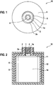
- Figure 1 shows a plan view of a battery cell 10 according to the invention with a housing 8.
- a first terminal 1 and a second terminal 2 protrude from the housing 8, the first terminal 1 being arranged within the second terminal 2.
- the first terminal 1 comprises aluminum, for example, and the second terminal 2 comprises copper, for example.
- the first terminal 1 comprises copper and the second terminal 2 comprises aluminum.
- the first terminal 1 is electrically insulated from the second terminal 2 by an insulator 6.
- the insulator 6 comprises, for example, a plastic, in particular a polyolefin, in particular a polyethylene or a polypropylene. Alternatively, instead of the insulator 6, an air gap can be present.
- a degassing valve 4 is arranged inside the first terminal 1.
- FIG 2 is the battery cell 10 according to Figure 1 shown in a sectional view.
- the battery cell 10 comprises an electrode assembly 14 with at least one first electrode (not shown) and a second electrode (not shown). Furthermore, the electrode assembly 14 includes, for example, a separator (not shown).
- the first electrode of the electrode assembly 14 is connected to a first current conductor 11.
- the first current conductor 11 is connected to the first terminal 1 in an electrically conductive manner.
- the first terminal 1 comprises a first screw thread 1a, which is designed as an internal thread. Alternatively, the first screw thread 1a of the first terminal 1 can also be an external thread.
- the second electrode of the electrode assembly 14 is connected to a second current conductor 12.
- the second current conductor 12 is connected to the second terminal 2 in an electrically conductive manner.
- the second terminal 2 comprises a second screw thread 2a, which is designed here as an external thread.
- the second screw thread 2a of the second terminal 2 can also be an internal thread.
- the direction of rotation of the first screw thread 1a of the first terminal 1 and the direction of rotation of the second screw thread 2a of the second terminal 2 match, for example, as well as the thread starting point of the first screw thread 1a and the second screw thread of 2a match.
- the thread length of the first screw thread 1a of the first terminal 1 corresponds to the thread length of the second screw thread 2a of the second terminal 2, for example.
- an insulator 6 is arranged between the first terminal 1 and the second terminal 2. This can only be located between the first terminal 1 and the second terminal 2 or alternatively also isolate a further area which is located, for example, between the electrode assembly 14 and one of the current collectors 11, 12 and / or which is located between the first current collector 11 and the second current arrester 12 is located.
- the first current collector 11 and the second current collector 12 are shown in FIG Figure 2 shown in one piece. Alternatively, these can also be made in several parts.
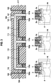
- FIG. 3 are three battery cells 10 according to FIG Figures 1 and 2 and a section from a battery module cover 117.
- the battery module cover 117 comprises, for example, a plastic, a metal, a metal alloy or a composite of plastic and metal or a metal alloy.
- the battery module cover 117 comprises a first module cover screw thread 101a, into which the first screw thread 1a of the first terminal 1 can be screwed.
- the battery module cover 117 comprises a second module cover screw thread 102a, into which the second screw thread 2a of the second terminal 2 can be screwed.
- the battery module cover 117 comprises first conductor tracks 111 for tapping a current from the first terminal 1 of the battery cells 10 and second conductor tracks 112 for tapping a current from the second terminal 2 of the battery cells 10.
- the first conductor tracks 111 and the second conductor tracks 112 are encased, for example, with a plastic .
- the first conductor tracks 111 open into a first module contact area 121 and the second conductor tracks 112 open into second module contact areas 122.
- Electrical contact can be made with the battery module cover 117 in the module contact areas 121, 122.
- the module contact areas 121, 122 protrude from the battery module cover 117.
- the module contact areas 121, 122 can be flush with the battery module cover 117 at the level of the latter.
- the first module contact area 121 is arranged around a degassing channel 104 and the second module contact area 122 is flat without a cutout.
- the first module contact area 121 can also be made continuous.
- the routing of the first conductor tracks 111 and the second conductor tracks 112 is also shown in FIG Figure 3 shown only as an example, it may differ from the illustration.
- two second module contact areas 122 are shown.
- the battery module cover 117 thus comprises two module contact areas 121, 122.
- the battery module cover 117 comprises several first module contact areas 121 and / or several second module contact areas 122.
- the degassing channel 104 opens on an outside of the battery module cover 117. If the first terminal 1 and the second terminal 2 of a battery cell 10 are screwed into the battery module cover 117, the degassing valve 4 is adjacent Battery cell 10 to the degassing channel 104, so that in the event of danger, gas can flow from the battery cell 10 via the degassing valve 4 into the degassing channel 104.
- the first conductor tracks 111 run adjacent to the degassing channel 104.
- the degassing channel 104 is formed, for example, by the first conductor tracks 111.
- FIG. 4 a section of a battery module 200 according to the invention is shown with a battery module cover 117 according to FIG Figure 3 and battery cells 10 according to FIG Figures 1, 2 and 3 .
- the battery cells 10 are in a state screwed into the battery module cover 117.
- the battery cells 10 are fixed to one another by a fixation 15 which is arranged transversely to the longitudinal axis of the battery cells 10.
- the fixation 15 is formed, for example, by a plate with, for example, circular recesses the size of a cell, into which the battery cells 10 are inserted transversely to their longitudinal axis, so that they are firmly connected to one another.
- the battery module cover 117 can furthermore comprise electronics, not shown in the figures, which serve to monitor the cell.
Landscapes
- Chemical & Material Sciences (AREA)
- Chemical Kinetics & Catalysis (AREA)
- Electrochemistry (AREA)
- General Chemical & Material Sciences (AREA)
- Engineering & Computer Science (AREA)
- Manufacturing & Machinery (AREA)
- Inorganic Chemistry (AREA)
- Materials Engineering (AREA)
- Composite Materials (AREA)
- Connection Of Batteries Or Terminals (AREA)
- Battery Mounting, Suspending (AREA)
- Gas Exhaust Devices For Batteries (AREA)
- Sealing Battery Cases Or Jackets (AREA)
Description
- Die vorliegende Erfindung bezieht sich auf eine Batteriezelle, insbesondere auf eine Lithiumionen-Batteriezelle, mit einem ersten Terminal, welches innerhalb eines zweiten Terminals angeordnet ist, sowie auf ein Batteriemodul, eine Batterie, nach dem Oberbegriff der unabhängigen Ansprüche.
- Eine Batteriezelle ist ein elektrochemischer Energiespeicher, der bei seiner Entladung die gespeicherte chemische Energie durch eine elektrochemische Reaktion in elektrische Energie umwandelt. Es zeichnet sich ab, dass in der Zukunft sowohl bei stationären Anwendungen, wie Windkraftanlagen, in Kraftfahrzeugen, die als Hybrid- oder Elektrokraftfahrzeuge ausgelegt sind, wie auch bei Elektronikgeräten neue Batteriesysteme zum Einsatz kommen werden, an die sehr hohen Anforderungen bezüglich Zuverlässigkeit, Sicherheit, Leistungsfähigkeit und Lebensdauer gestellt werden. Aufgrund ihrer großen Energiedichte werden insbesondere Lithium-Ionen-Batterien als Energiespeicher für elektrisch angetriebene Kraftfahrzeuge verwendet.
- In der
DE 102012215205 A1 ist ein Zellverbinder offenbart, welcher eine Abdeckeinrichtung mit einem Innengewinde aufweist. Das Innengewinde des Zellverbinders ist mit einem Außengewinde einer Batteriezelle verbindbar. - Die
DE 2901427 A1 offenbart eine Akkumulatorbatterie mit einem Innengewinde, in welches ein Rohr mit einem Außengewinde eindrehbar ist. Das Gehäuse weist ein weiteres Innengewinde auf, welches koaxial zu dem ersten Innengewinde angeordnet ist, und mit einem Außengewinde eines Werkzeuges zusammenwirkt, um das drehbare Rohr in die Batterie hinein oder aus dieser heraus zu drehen. - In der
DE 102012218162 A1 ist eine Vorrichtung zur Verbindung mehrerer Energiespeichermodule miteinander offenbart. Dabei sind jeweils Schrauben zum Verbinden der Module vorgesehen, welche ein Außengewinde aufweisen. Ferner weisen die Schrauben im Schraubenkopf ein Innengewinde auf, welches konzentrisch zu dem Außengewinde angeordnet ist. - Die
EP 2675000 A1 offenbart eine Batteriezelle mit zwei Terminals, welche parallel zueinander aus derselben Fläche des Gehäuses der Batteriezelle hervorragen. Die beiden Terminals sind dabei jeweils bolzenartig ausgebildet und umfassen ein Außengewinde, auf welches jeweils eine Mutter aufgeschraubt ist. - Weiterer relevanter Stand der Technik ist in folgenden Dokumenten offenbart, die sich alle auf Terminale der sekundären Batterien mit Schraubgewinde beziehen:
EP 1 791 198 A2 ,GB 2 248 338 A WO 94/23460 A1 US 2001/014418 A1 undDE 101 22 682 A1 . - Erfindungsgemäß werden eine Batteriezelle mit einem ersten Terminal und einem zweiten Terminal, wobei das erste Terminal innerhalb des zweiten Terminals angeordnet ist, sowie ein Batteriemodul, eine Batterie und ein Verfahren zur Herstellung des Batteriemoduls, mit den kennzeichnenden Merkmalen der unabhängigen Ansprüche bereitgestellt.
- Die erfindungsgemäße Batteriezelle mit einem ersten Terminal, welches elektrisch leitfähig mit einer ersten Elektrode verbunden ist, und einem zweiten Terminal, welches elektrisch leitfähig mit einer zweiten Elektrode verbunden ist, wobei das erste Terminal innerhalb des zweiten Terminals angeordnet ist, und das erste Terminal ein erstes Schraubgewinde und das zweite Terminal ein zweites Schraubgewinde umfasst, dadurch gekennzeichnet, dass die außerhalb der Batteriezelle liegende Enden der Schraubgewinde des ersten Terminals und des zweiten Terminals auf gleicher Höhe ansetzen, gemäß dem unabhängigen Anspruch 1 und bietet den Vorteil, dass die Terminals nur wenig Raum in der Umgebung der Batteriezelle einnehmen. Der Raum, der durch das erste Terminal und durch das zweite Terminal der Batteriezelle eingenommen wird ist deutlich kleiner im Vergleich zu herkömmlichen Batteriezellen mit zwei Terminals, welche nicht innerhalb einander angeordnet sind. Im Vergleich zu Terminals einer Batteriezelle, welche beispielsweise auf zwei sich gegenüberliegenden Seitenflächen der Batteriezelle angeordnet sind, wie es beispielsweise bei Rundzellen üblich ist, steht nun eine dieser Seitenflächen der Batteriezelle für andere Funktionen, wie beispielsweise der Kühlung der Batteriezelle, zur Verfügung. Desweiteren wird bei einem Zusammenbau erfindungsgemäßer Batteriezellen Platz eingespart, da die Terminals nur auf einer Seitenfläche der Batteriezellen hervor stehen und beispielsweise auf der gegenüberliegenden Seitenfläche kein Terminal hervor steht. Desweiteren werden beim Zusammenbau mehrerer erfindungsgemäßer Batteriezellen Arbeitsschritte eingespart, da die Batteriezelle bei deren Montage nicht gedreht werden muss, sondern nur auf einer Seitenfläche kontaktiert wird.
- Weitere vorteilhafte Ausführungsformen der vorliegenden Batteriezelle ergeben sich aus den Unteransprüchen.
- Gemäß der Erfindung, weisen das erste und das zweite Terminal je ein Schraubgewinde auf. Ein Schraubgewinde bietet den Vorteil, dass eine Schraubverbindung wieder gelöst werden kann. Im Fall eines Defekts einer Batteriezelle kann diese somit ausgetauscht werden, ohne dass das ganze Batteriemodul entsorgt werden muss. Desweiteren vorteilhaft bei einer Schraubverbindung ist, dass diese mehrmals gelöst und wieder neu verbunden werden kann, was beispielsweise bei Schweißverbindungen nicht möglich ist. Auch durch ein mehrmaliges Lösen und wieder neu Verbinden einer Schraubverbindung nimmt die Verbindungsqualität nicht ab. Zudem vorteilhaft ist, dass Schraubgewinde temperaturbeständig sind und keine Gefügeveränderungen beim Verbindungsvorgang des Schraubens auftreten. Desweiteren ist es einfach Schraubverbindungen aus unterschiedlichen Werkstoffen herzustellen. Zudem vorteilhaft bei einer Schraubverbindung ist, dass beispielsweise im Vergleich zu einer Schweißverbindung keine problematischen Partikel erzeugt werden, welche später beispielsweise einen Kurzschluss verursachen können.
- In einer vorteilhaften Ausführungsform ist das Schraubgewinde des ersten Terminals ein Innengewinde und das Schraubgewinde des zweiten Terminals ein Außengewinde. Auf diese Weise ist der Raum zwischen dem ersten Terminal und dem zweiten Terminal nicht von einem Gewinde begrenzt, sodass beispielsweise ein Isolator in diesen einfach eingebracht werden kann, ohne dass dieser durch das Gewinde beschädigt werden kann. In einer alternativen Ausführungsform ist das Schraubgewinde des ersten Terminals ein Außengewinde und das Schraubgewinde des zweiten Terminals ein Innengewinde. Vorteilhaft hierbei ist, dass der Raum innerhalb des ersten Terminals nicht von einem Gewinde begrenzt ist, sodass dort beispielsweise in den Raum innerhalb des ersten Terminals ein Entgasungsventil eingebracht werden kann, ohne dass die Gefahr einer Beschädigung des Entgasungsventils besteht.
- In einer weiteren vorteilhaften Ausführungsform stimmen die Drehrichtung und die Steigung des Schraubgewindes des ersten Terminals und des Schraubgewindes des zweiten Terminals überein. Dadurch ist es möglich das erste Terminal und das zweite Terminal gleichzeitig zu kontaktieren, beispielsweise indem beide Terminals gleichzeitig in einen Moduldeckel geschraubt werden, sodass ein Abgreifen des Stromes erfolgen kann. Die elektrische Verbindung der Terminals der Batteriezellen ist so auf einfache Weise realisierbar. Durch ein gleichzeitiges Einschrauben des ersten und des zweiten Terminals werden zudem Zeit und Arbeitsschritte eingespart.
- Gemäß der Erfindung, stimmt der Gewindeansatzpunkt des Schraubgewindes des ersten Terminals und des Schraubgewindes des zweiten Terminals überein. Mit dem Ausdruck Gewindeansatzpunkt ist hier gemeint, dass die außerhalb der Batteriezelle liegenden Enden der Schraubgewinde des ersten und zweiten Terminals auf gleicher Höhe ansetzen und nicht versetzt zueinander. Dadurch wird gewährleistet, dass die Verschraubung der beiden Terminals, beispielsweise mit einem Moduldeckel, gleichartig erfolgt, sodass eine gute und feste Verbindung resultiert. Desweiteren ist es aus gleichen Gründen vorteilhaft, wenn die Gewindelänge des Schraubgewindes des ersten Terminals und des Schraubgewindes des zweiten Terminals übereinstimmt. Wird ein Moduldeckel mit dem ersten und dem zweiten Terminal verschraubt, so haben beide Schraubgewinde den gleichen Gewindeanschlag.
- In einer besonders bevorzugten Ausführungsform umfasst das erste Terminal der Batteriezelle Kupfer und das zweite Terminal Aluminium. Da das erste Terminal innerhalb des zweiten Terminals angeordnet ist, wird weniger Kupfer benötigt als Aluminium wodurch sich Vorteile bezüglich der Kostenseite ergeben, da der Werkstoff Kupfer teurer ist als der Werkstoff Aluminium. Dabei bildet das zweite Terminal beispielsweise das positive Terminal. Vorteilhaft hierbei ist, dass das Gehäuse der Batteriezelle beispielsweise auf einfache Weise elektrisch leitend mit dem außen liegenden zweiten Terminal verbunden werden kann, sodass auf dem Gehäuse beispielsweise ein positives Potenzial liegt, was diesem eine Resistenz gegen Korrosion verleiht. Alternativ kann auch das innen liegende erste Terminal elektrisch leitend mit dem Gehäuse der Batteriezelle verbunden werden, sodass beispielsweise ein negatives Potenzial auf dem Gehäuse der Batteriezellen liegt. In einer alternativen Ausführungsform sind sowohl das erste Terminal als auch das zweite Terminal mittels eines Isolierungsmaterials elektrisch von dem Gehäuse der Batteriezelle isoliert, sodass das Gehäuse der Batteriezellen potenzialfrei ist.
- In einer alternativen Ausführungsform umfasst das erste Terminal Aluminium und das zweite Terminal umfasst Kupfer.
- Aluminium bietet den Vorteil, dass es leicht und kostengünstig ist und zudem in großen Mengen verfügbar. Kupfer hingegen ist vorteilhaft bezüglich seiner Korrosionsbeständigkeit, was unter anderem eine hohe Lebensdauer mit sich bringt. Zudem ist Kupfer gut zu verarbeiten und kann auch bei niedrigen Temperaturen optimal verformt werden.
- In einer weiteren besonders bevorzugten Ausführungsform umfassen beide Terminals Aluminium, wobei sich die bereits genannten Vorteile ergeben. Hierbei kann beispielsweise zumindest ein Terminal aus Aluminium eine metallische Beschichtung aufweisen.
- In einer bevorzugten Ausführungsform sind das erste Terminal und das zweite Terminal, zumindest im Bereich zwischen deren Schraubgewinden, mittels eines Luftspalts und/oder mittels eines Isolators voneinander elektrisch isoliert. Dadurch ist die Sicherheit der Batteriezelle deutlich erhöht, da durch den Luftspalt, und in einer bevorzugten Ausführung durch den Isolator, die Gefahr eines Kurzschlusses der Batteriezelle unterbunden wird.
- Vorteilhaft umfasst der Isolator einen Kunststoff, insbesondere ein Polyolefin, insbesondere ein Polyethylen oder ein Polypropylen. Durch einen Kunststoff können zuverlässig eventuell auftretende mechanische Belastungen durch die Schraubgewinde des ersten und des zweiten Terminals aufgenommen werden. Polyolefine sind gleichzeitig robust und flexibel und weisen eine hohe mechanische und chemische Stabilität auf. Von diesen weist beispielsweise Polyethylen eine hohe Zähigkeit, eine geringe Wasseraufnahme und Wasserdampfdurchlässigkeit, sowie eine hohe Beständigkeit gegen Chemikalien auf und ist zudem gut zu verarbeiten und kostengünstig. Polypropylen weist eine geringe Wasseraufnahme auf, ist chemisch beständig, elektrisch isolierend sowie gut zu verarbeiten und kostengünstig.
- In einer besonders bevorzugten Ausführungsform ist innerhalb des ersten Terminals und/oder des zweiten Terminals ein Entgasungsventil angeordnet. Dadurch lässt sich weiterer Platz auf den Außenflächen der Batteriezelle einsparen, der dann für andere Komponenten, beispielsweise für eine Kühlungseinrichtung, zur Verfügung steht. Das Entgasungsventil kann auch zwischen dem ersten Terminal und dem zweiten Terminal angeordnet sein.
- Desweiteren ist ein Batteriemodul mit zumindest zwei erfindungsgemäßen Batteriezellen sowie ein Batteriemoduldeckel, welcher pro Batteriezelle zumindest zwei Moduldeckel-Schraubgewinde zum Einschrauben der Batteriezelle umfasst, vorgesehen. Es ist besonders vorteilhaft, wenn der Batteriemoduldeckel mit einem Kunststoff ummantelte Leiterbahnen umfasst. Die Leiterbahnen sind durch den Kunststoff voneinander isoliert, sodass eine zuverlässige und sichere elektrische Verbindung zwischen den Batteriezellen über den Moduldeckel gewährleistet ist. Der Vorteil des Einsatzes von Kunststoff zur Isolierung der Leiterbahnen voneinander ist, dass Kunststoff ein geringes Gewicht aufweist, beispielsweise im Vergleich zu Metallen. Weiterhin vorteilhaft ist, dass Bauteile aus Kunststoff sehr einfach und kostengünstig hergestellt werden können und einfach wiederverwertet werden können. In den Moduldeckel ist desweiteren beispielsweise ein Entgasungskanal und/oder eine Elektronik zur Zellüberwachung integriert.
- In einer besonders bevorzugten Ausführungsform sind die Batteriezellen als Batterie-Rundzellen ausgeführt. Vorteilhaft hierbei ist, dass die Batterie-Rundzellen bei der Montage im Batteriemodul dicht nebeneinander angeordnet werden können, und dennoch einzelne Batteriezellen individuell über die Schraubverbindung gelöst und neu verbunden werden können, beispielsweise im Falle eines Defekts einer Batteriezelle. Es muss dann nicht das ganze Modul ausgetauscht werden sondern lediglich die defekte Batteriezelle, was erhebliche Material- und Arbeitskosten einspart. Desweiteren sind die Batteriezellen beispielsweise insbesondere quer zu einer Längsachse der Batteriezellen miteinander fixiert, sodass eine stabile Anordnung der Batteriezellen im Batteriemodul gewährleistet ist. Die Fixierung geschieht beispielsweise mittels einer Platte, welche Ausnehmungen in Zellgröße aufweist, durch welche die Batteriezellen quer zu deren Längsachse eingeschoben und so miteinander fixiert werden. Beim Arbeitsschritt des Einschraubens werden so beispielsweise gleichzeitig die elektrische Kontaktierung sowie auch die mechanische Fixierung hergestellt.
- Vorteilhaft ist ein Verfahren zur Herstellung eines Batteriemoduls wobei das erste Terminal und das zweite Terminal jeder Batteriezelle synchron zueinander in je ein Moduldeckel-Schraubgewinde des Batteriemoduldeckels eingeschraubt werden. Durch das Einschrauben der Batteriezellen in den Batteriemoduldeckel werden das erste Terminal und das zweite Terminal der Batteriezelle gleichzeitig elektrisch kontaktiert, sodass Zeit und Arbeitskosten eingespart werden. Die Montage der Batteriezellen gestaltet sich zudem sehr einfach.
- Die erfindungsgemäße Batterie wird vorteilhaft in einem Elektrofahrzeug, in einem Hybridfahrzeug oder in einem Plug-In-Hybridfahrzeug verwendet.
- Ausführungsformen der vorliegenden Erfindung sind in der Zeichnung dargestellt und in der nachfolgenden Figurenbeschreibung näher erläutert. Es zeigt:
- Fig. 1:
- die schematische Darstellung einer Aufsicht auf eine erfindungsgemäße Batteriezelle mit einem ersten Terminal, welches innerhalb eines zweiten Terminals angeordnet ist,
- Fig. 2:
- die schematische Darstellung eines Längsschnitts durch die Längsachse der erfindungsgemäßen Batteriezelle gemäß
Figur 1 , - Fig. 3:
- die schematische Darstellung eines Ausschnitts eines Batteriemoduldeckels und dreier erfindungsgemäßer Batteriezellen gemäß der
Figuren 1 und 2 , und - Fig. 4:
- die schematische Darstellung eines Ausschnitts eines erfindungsgemäßen Batteriemoduls.
-
Figur 1 zeigt eine Aufsicht auf eine erfindungsgemäße Batteriezelle 10 mit einem Gehäuse 8. Aus dem Gehäuse 8 ragen ein erstes Terminal 1 und ein zweites Terminal 2 hervor, wobei das erste Terminal 1 innerhalb des zweiten Terminals 2 angeordnet ist. Das erste Terminal 1 umfasst beispielsweise Aluminium und das zweite Terminal 2 umfasst beispielsweise Kupfer. Alternativ umfasst das erste Terminal 1 Kupfer und das zweite Terminal 2 umfasst Aluminium. Das erste Terminal 1 ist von dem zweiten Terminal 2 durch einen Isolator 6 elektrisch isoliert. Der Isolator 6 umfasst beispielsweise einen Kunststoff, insbesondere ein Polyolefin, insbesondere ein Polyethylen oder ein Polypropylen. Alternativ kann anstelle des Isolators 6 ein Luftspalt vorhanden sein. Innerhalb des ersten Terminals 1 ist ein Entgasungsventil 4 angeordnet. - In
Figur 2 ist die Batteriezelle 10 gemäßFigur 1 in einer Schnittdarstellung dargestellt. Die Batteriezelle 10 umfasst einen Elektrodenverbund 14 mit zumindest einer nicht dargestellten ersten Elektrode und einer nicht dargestellten zweiten Elektrode. Desweiteren umfasst der Elektrodenverbund 14 beispielsweise einen nicht dargestellten Separator. Die erste Elektrode des Elektrodenverbunds 14 ist mit einem ersten Stromableiter 11 verbunden. Der erste Stromableiter 11 ist mit dem ersten Terminal 1 elektrisch leitend verbunden. Das erste Terminal 1 umfasst ein erstes Schraubgewinde 1a, welches als Innengewinde ausgeführt ist. Alternativ kann das erste Schraubgewinde 1a des ersten Terminals 1 auch ein Außengewinde sein. - Die zweite Elektrode des Elektrodenverbunds 14 ist mit einem zweiten Stromableiter 12 verbunden. Der zweite Stromableiter 12 ist mit dem zweiten Terminal 2 elektrisch leitend verbunden. Das zweite Terminal 2 umfasst ein zweites Schraubgewinde 2a, welches hier als Außengewinde ausgeführt ist. Alternativ kann das zweite Schraubgewinde 2a des zweiten Terminals 2 auch ein Innengewinde sein. Die Drehrichtung des ersten Schraubgewindes 1a des ersten Terminals 1 und die Drehrichtung des zweiten Schraubgewindes 2a des zweiten Terminals 2 stimmen beispielsweise überein, sowie beispielsweise auch der Gewindeansatzpunkt des ersten Schraubgewindes 1a und des zweiten Schraubgewindes des 2a übereinstimmt. Desweiteren stimmt die Gewindelänge des ersten Schraubgewindes 1a des ersten Terminals 1 mit der Gewindelänge des zweiten Schraubgewindes 2a des zweiten Terminals 2 beispielsweise überein. Zwischen dem ersten Terminal 1 und dem zweiten Terminal 2 ist beispielsweise ein Isolator 6 angeordnet. Dieser kann sich lediglich zwischen dem ersten Terminal 1 und dem zweiten Terminal 2 befinden oder alternativ auch einen weiterführenden Bereich isolieren, welcher sich beispielsweise zwischen dem Elektrodenverbund 14 und einem der Stromableiter 11, 12 befindet und/oder welcher sich zwischen dem ersten Stromableiter 11 und dem zweiten Stromableiter 12 befindet. Der erste Stromableiter 11 und der zweite Stromableiter 12 sind in
Figur 2 einteilig dargestellt. Alternativ können diese auch mehrteilig ausgeführt sein. - In
Figur 3 sind drei Batteriezellen 10 gemäß derFiguren 1 und 2 dargestellt sowie ein Ausschnitt aus einem Batteriemoduldeckel 117. Der Batteriemoduldeckel 117 umfasst beispielsweise einen Kunststoff, ein Metall, eine Metalllegierung oder einen Verbund aus Kunststoff und Metall oder einer Metalllegierung. Der Batteriemoduldeckel 117 umfasst ein erstes Moduldeckel-Schraubgewinde 101a, in welches das erste Schraubgewinde 1a des ersten Terminals 1 einschraubbar ist. Der Batteriemoduldeckel 117 umfasst ein zweites Moduldeckel-Schraubgewinde 102a, in welches das zweite Schraubgewinde 2a des zweiten Terminals 2 einschraubbar ist. Desweiteren umfasst der Batteriemoduldeckel 117 erste Leiterbahnen 111 zum Abgreifen eines Stromes des ersten Terminals 1 der Batteriezellen 10 sowie zweite Leiterbahnen 112 zum Abgreifen eines Stromes des zweiten Terminals 2 der Batteriezellen 10. Die ersten Leiterbahnen 111 und die zweiten Leiterbahnen 112 sind beispielsweise mit einem Kunststoff ummantelt. Die ersten Leiterbahnen 111 münden in einen ersten Modulkontaktbereich 121 und die zweiten Leiterbahnen 112 münden in zweite Modulkontaktbereiche 122. In den Modulkontaktbereichen 121, 122 kann der Batteriemoduldeckel 117 elektrisch kontaktiert werden. InFigur 3 stehen die Modulkontaktbereiche 121, 122 aus dem Batteriemoduldeckel 117 hervor. Alternativ können die Modulkontaktbereiche 121, 122 auf Höhe des Batteriemoduldeckels 117 mit diesem ebenflächig abschließen. InFigur 3 ist der erste Modulkontaktbereich 121 um einen Entgasungskanal 104 herum angeordnet und der zweite Modulkontaktbereich 122 ist flächig ohne Aussparung ausgeführt. Alternativ kann der erste Modulkontaktbereich 121 ebenfalls durchgehend ausgeführt sein. Die Führung der ersten Leiterbahnen 111 und der zweiten Leiterbahnen 112 ist desweiteren inFigur 3 nur beispielhaft dargestellt, sie kann von der Darstellung abweichen. InFigur 3 sind zwei zweite Modulkontaktbereiche 122 dargestellt. Alternativ ist entsprechend des ersten Modulkontaktbereichs 121 nur ein zweiter Modulkontaktbereich 122 vorhanden, in den alle zweiten Leiterbahnen 112 münden. Der Batteriemoduldeckel 117 umfasst somit zwei Modulkontaktbereiche 121, 122. Weiterhin alternativ umfasst der Batteriemoduldeckel 117 mehrere erste Modulkontaktbereiche 121 und/oder mehrere zweite Modulkontaktbereiche 122. - Der Entgasungskanal 104 mündet auf einer Außenseite des Batteriemoduldeckels 117. Sind das erste Terminal 1 und das zweite Terminal 2 einer Batteriezelle 10 in den Batteriemoduldeckel 117 eingeschraubt, so grenzt das Entgasungsventil 4 der Batteriezelle 10 an den Entgasungskanal 104, sodass im Gefahrenfall Gas aus der Batteriezelle 10 über das Entgasungsventil 4 in den in den Entgasungskanal 104 strömen kann. Angrenzend an den Entgasungskanal 104 verlaufen beispielsweise die ersten Leiterbahnen 111. Alternativ wird der Entgasungskanal 104 beispielsweise durch die ersten Leiterbahnen 111 gebildet.
- In
Figur 4 ist ein Ausschnitt eines erfindungsgemäßen Batteriemoduls 200 dargestellt mit einem Batteriemoduldeckel 117 gemäßFigur 3 und Batteriezellen 10 gemäß derFiguren 1, 2 und3 . die Batteriezellen 10 befinden sich in einem in den Batteriemoduldeckel 117 eingeschraubten Zustand. Der Übersichtlichkeit halber sind inFigur 4 nicht alle Komponenten der Batteriezellen 10 und des Batteriemoduldeckels 117 dargestellt. Die Batteriezellen 10 sind durch eine Fixierung 15 welche quer zu der Längsachse der Batteriezellen 10 angeordnet ist miteinander fixiert. Die Fixierung 15 ist beispielsweise durch eine Platte mit beispielsweise kreisförmigen Ausnehmungen in Zellgröße gebildet, in welche die Batteriezellen 10 quer zu deren Längsachse eingeschoben werden, sodass sie fest miteinander verbunden sind. Der Batteriemoduldeckel 117 kann desweiteren eine in den Figuren nicht dargestellte Elektronik umfassen, welche zur Überwachung der Zelle dient.
Claims (13)
- Batteriezelle (10), insbesondere Lithiumionen-Batteriezelle, mit einem ersten Terminal (1) welches elektrisch leitfähig mit einer ersten Elektrode verbunden ist und einem zweiten Terminal (2) welches elektrisch leitfähig mit einer zweiten Elektrode verbunden ist, wobei das erste Terminal (1) innerhalb des zweiten Terminals (2) angeordnet ist und das erste Terminal (1) ein erstes Schraubgewinde (1a) und das zweite Terminal (2) ein zweites Schraubgewinde (2a) umfasst,
dadurch gekennzeichnet, dass
die außerhalb der Batteriezelle (10) liegenden Enden der Schraubgewinde (1a, 2a) des ersten Terminals (1) und zweiten Terminals (2) auf gleicher Höhe ansetzen. - Batteriezelle (10) nach Anspruch 1, dadurch gekennzeichnet, dass das Schraubgewinde (1a) des ersten Terminals (1) ein Innengewinde und das Schraubgewinde (2a) des zweiten Terminals (2) ein Außengewinde ist.
- Batteriezelle (10) nach einem der Ansprüche 1 oder 2, dadurch gekennzeichnet, dass die Drehrichtung und die Steigung des Schraubgewindes (1a) des ersten Terminals (1) und des Schraubgewindes (2a) des zweiten Terminals (2) übereinstimmen.
- Batteriezelle (10) nach einem der Ansprüche 1-3, dadurch gekennzeichnet, dass die Gewindelänge des Schraubgewindes (1a) des ersten Terminals (1) und des Schraubgewindes (2a) des zweiten Terminals (2) übereinstimmt.
- Batteriezelle (10) nach einem der vorhergehenden Ansprüche, dadurch gekennzeichnet, dass das erste Terminal (1) Aluminium umfasst und das zweite Terminal (2) Kupfer umfasst oder dass das erste Terminal (1) Kupfer umfasst und das zweite Terminal (2) Aluminium umfasst oder dass sowohl das erste Terminal (1) als auch das zweite Terminal (2) Aluminium umfassen.
- Batteriezelle (10) nach einem der Ansprüche 1-5, dadurch gekennzeichnet, dass das erste Terminal (1) und das zweite Terminal (2), zumindest im Bereich zwischen deren Schraubgewinden (1a, 2a), mittels eines Luftspalts und/oder mittels eines Isolators (6) voneinander elektrisch isoliert sind.
- Batteriezelle (10) nach Anspruch 6, dadurch gekennzeichnet, dass der Isolator (6) einen Kunststoff, insbesondere ein Polyolefin, insbesondere ein Polyethylen oder ein Polypropylen umfasst.
- Batteriezelle (10) nach einem der vorhergehenden Ansprüche, dadurch gekennzeichnet, dass innerhalb des ersten Terminals (1) und/oder des zweiten Terminals (2) ein Entgasungsventil (4) angeordnet ist.
- Batteriemodul (200) mit zumindest zwei Batteriezellen (10) nach einem der Ansprüche 1-8 und einem Batteriemoduldeckel (117), welcher pro Batteriezelle (10) zumindest zwei Moduldeckel-Schraubgewinde (101a, 102a) zum Einschrauben der Batteriezellen (10) umfasst.
- Batteriemodul (200) nach Anspruch 9, dadurch gekennzeichnet, dass der Batteriemoduldeckel (117) mit einem Kunststoff ummantelte Leiterbahnen (111, 112) umfasst.
- Batteriemodul (200) nach einem der Ansprüche 9 oder 10, dadurch gekennzeichnet, dass die Batteriezellen (10) insbesondere Batterie-Rundzellen sind und, dass die Batteriezellen (10) durch eine Fixierung (15), welche insbesondere quer zu einer Längsachse der Batteriezellen (10) angeordnet ist, miteinander fixiert sind.
- Batteriemodul (200) nach einem der Ansprüche 9-11, dadurch gekennzeichnet, dass der Batteriemoduldeckel (117) einen Entgasungskanal (104) und/oder eine Elektronik zur Zellüberwachung umfasst.
- Batterie, umfassend eine Batteriezelle (10) nach einem der Ansprüche 1-8 und/oder ein Batteriemodul (200) nach einem der Ansprüche 9-12.
Applications Claiming Priority (2)
| Application Number | Priority Date | Filing Date | Title |
|---|---|---|---|
| DE102015210671.3A DE102015210671A1 (de) | 2015-06-11 | 2015-06-11 | Batteriezelle mit einem innerhalb eines zweiten Terminals angeordneten ersten Terminal |
| PCT/EP2016/062646 WO2016198332A1 (de) | 2015-06-11 | 2016-06-03 | Batteriezelle mit einem innerhalb eines zweiten terminals angeordneten ersten terminal |
Publications (2)
| Publication Number | Publication Date |
|---|---|
| EP3308415A1 EP3308415A1 (de) | 2018-04-18 |
| EP3308415B1 true EP3308415B1 (de) | 2021-01-13 |
Family
ID=56121057
Family Applications (1)
| Application Number | Title | Priority Date | Filing Date |
|---|---|---|---|
| EP16728893.5A Active EP3308415B1 (de) | 2015-06-11 | 2016-06-03 | Batteriezelle mit einem innerhalb eines zweiten terminals angeordneten ersten terminal |
Country Status (6)
| Country | Link |
|---|---|
| US (1) | US10483520B2 (de) |
| EP (1) | EP3308415B1 (de) |
| JP (1) | JP6568604B2 (de) |
| KR (1) | KR20180017129A (de) |
| DE (1) | DE102015210671A1 (de) |
| WO (1) | WO2016198332A1 (de) |
Families Citing this family (6)
| Publication number | Priority date | Publication date | Assignee | Title |
|---|---|---|---|---|
| DE102018122080A1 (de) | 2018-09-11 | 2020-03-12 | Webasto SE | Batteriemodul und Verfahren zum Herstellen eines Batteriemoduls |
| DE102019207207A1 (de) | 2019-05-17 | 2020-11-19 | Volkswagen Aktiengesellschaft | Batteriemodul für ein Kraftfahrzeug |
| CN115133202B (zh) * | 2022-06-09 | 2024-08-09 | 徐州盛嘉志新能源科技有限公司 | 自带保护的钠电池组盒 |
| DE102022002480A1 (de) * | 2022-07-07 | 2024-01-18 | Mercedes-Benz Group AG | Batteriezelle für ein Batteriemodul eines elektrischen Energiespeichers sowie Batteriemodul |
| DE102023003867A1 (de) | 2023-09-23 | 2025-03-27 | Mercedes-Benz Group AG | Batteriezellaufbau und Verfahren zur Fertigung |
| DE102024103089A1 (de) * | 2024-02-05 | 2025-08-07 | Bayerische Motoren Werke Aktiengesellschaft | HVS-Konzept mit tauschbarer Zelle |
Citations (2)
| Publication number | Priority date | Publication date | Assignee | Title |
|---|---|---|---|---|
| US20010014418A1 (en) * | 1999-12-20 | 2001-08-16 | Seiji Nemoto | Battery |
| DE10122682A1 (de) * | 2000-05-12 | 2001-11-29 | Honda Motor Co Ltd | Zellenmodulstruktur |
Family Cites Families (14)
| Publication number | Priority date | Publication date | Assignee | Title |
|---|---|---|---|---|
| SE409925B (sv) | 1978-01-19 | 1979-09-10 | Nordiska Ackumulator Fabriker | Ventilations- och nivaregleringsanordning vid ackumulatorbatterier |
| US5135824A (en) * | 1990-09-28 | 1992-08-04 | Globe-Union Inc. | Coaxial terminal construction for a sealed pressurized battery |
| NZ263988A (en) * | 1993-04-05 | 1997-10-24 | Black & Decker Inc | Battery pack for cordless implements |
| JPH08222201A (ja) * | 1995-02-14 | 1996-08-30 | Toyota Autom Loom Works Ltd | 電 池 |
| JP4733248B2 (ja) * | 2000-06-20 | 2011-07-27 | 本田技研工業株式会社 | セルモジュール構造 |
| DE102004008389A1 (de) * | 2004-02-20 | 2005-09-08 | Bayerische Motoren Werke Ag | Hubvariabler Ventiltrieb für eine Brennkraftmaschine |
| US7749651B2 (en) * | 2005-11-28 | 2010-07-06 | Greatbatch Ltd. | Terminal connector for connecting an electrochemical cell to a medical device |
| US8568915B2 (en) * | 2006-08-11 | 2013-10-29 | Johnson Controls—SAFT Power Solutions LLC | Battery with integrally formed terminal |
| JP5540588B2 (ja) * | 2008-10-20 | 2014-07-02 | 日産自動車株式会社 | 双極型二次電池、組電池およびそれらの電池を搭載した車両 |
| JP5364650B2 (ja) * | 2010-07-01 | 2013-12-11 | Udトラックス株式会社 | 蓄電デバイス、蓄電デバイス間の接続構造、蓄電モジュール |
| JP2012022955A (ja) * | 2010-07-16 | 2012-02-02 | Panasonic Corp | 二次電池の製造方法および二次電池 |
| US9287550B2 (en) | 2012-06-11 | 2016-03-15 | Samsung Sdi Co., Ltd. | Rechargeable battery |
| DE102012215205A1 (de) | 2012-08-28 | 2014-03-06 | Robert Bosch Gmbh | Zellenverbinder, Batteriezellenmodul, Batterie, Verfahren zur Herstellung eines Batteriezellenmoduls und Kraftfahrzeug |
| DE102012218162B4 (de) | 2012-10-04 | 2023-12-14 | Bayerische Motorenwerke Aktiengesellschaft | Energiespeicheranordnung |
-
2015
- 2015-06-11 DE DE102015210671.3A patent/DE102015210671A1/de not_active Withdrawn
-
2016
- 2016-06-03 JP JP2017564043A patent/JP6568604B2/ja active Active
- 2016-06-03 EP EP16728893.5A patent/EP3308415B1/de active Active
- 2016-06-03 WO PCT/EP2016/062646 patent/WO2016198332A1/de not_active Ceased
- 2016-06-03 US US15/735,261 patent/US10483520B2/en active Active
- 2016-06-03 KR KR1020187000813A patent/KR20180017129A/ko not_active Withdrawn
Patent Citations (2)
| Publication number | Priority date | Publication date | Assignee | Title |
|---|---|---|---|---|
| US20010014418A1 (en) * | 1999-12-20 | 2001-08-16 | Seiji Nemoto | Battery |
| DE10122682A1 (de) * | 2000-05-12 | 2001-11-29 | Honda Motor Co Ltd | Zellenmodulstruktur |
Also Published As
| Publication number | Publication date |
|---|---|
| WO2016198332A1 (de) | 2016-12-15 |
| US20180175361A1 (en) | 2018-06-21 |
| EP3308415A1 (de) | 2018-04-18 |
| US10483520B2 (en) | 2019-11-19 |
| DE102015210671A1 (de) | 2016-12-15 |
| JP2018517264A (ja) | 2018-06-28 |
| JP6568604B2 (ja) | 2019-08-28 |
| KR20180017129A (ko) | 2018-02-20 |
Similar Documents
| Publication | Publication Date | Title |
|---|---|---|
| WO2016198332A1 (de) | Batteriezelle mit einem innerhalb eines zweiten terminals angeordneten ersten terminal | |
| EP2705557B1 (de) | Lithiumsekundärzellenanordnung | |
| WO2010012337A1 (de) | Batterie mit einer in einem batteriegehäuse angeordneten wärmeleitplatte zum temperieren der batterie | |
| WO2009103527A1 (de) | Batterie mit mehreren einzelzellen | |
| DE102012214964A1 (de) | Batteriezelle, Batterie und Kraftfahrzeug | |
| WO2017076699A1 (de) | Dichtsystem für poldurchführung | |
| DE102022121989A1 (de) | Deckelbaugruppe, energiespeicherzelle, batteriemodul und verfahren zur herstellung einer deckelbaugruppe | |
| WO2011054586A1 (de) | Verfahren zur verbindung eines batteriepols an einer ersten batteriezelle mit einem batteriepol an einer zweiten batteriezelle sowie batterie mit miteinander verbundenen batteriezellen und batteriesystem | |
| EP3284119B1 (de) | Batterie mit prismatischem metallgehäuse | |
| WO2014095167A2 (de) | Batteriezelle mit buchsenartig ausgebildetem zellterminal und korrespondierender zellverbinder | |
| DE102021002756A1 (de) | Rundzelle, Batteriemodul und Fahrzeug | |
| DE102021006016A1 (de) | Rundzelle für einen elektrischen Energiespeicher eines Kraftfahrzeugs, insbesondere eines Kraftwagens | |
| DE102011109211A1 (de) | Verbindungselement zur elektrisch leitfähigen Kontaktierung | |
| WO2010063364A1 (de) | Einzelzelle für eine batterie und verfahren zu deren herstellung | |
| DE102015207069A1 (de) | Batterie mit prismatischem Metallgehäuse | |
| WO2022248253A1 (de) | Batteriezelle | |
| DE102008034865A1 (de) | Batteriezelle und Batterie mit mehreren Batteriezellen | |
| DE102019103614B4 (de) | Überstromschutzvorrichtung für eine Energiespeicherzelle, Elektrode für eine Energiespeicherzelle, Energiespeicherzelle und Verfahren zur Herstellung einer Elektrode für eine Energiespeicherzelle | |
| DE102013021203A1 (de) | Einzelzelle für eine Batterie und Batterie | |
| DE102022123447A1 (de) | Batteriezelle, Hochvoltbatterie und Kraftfahrzeug | |
| DE102006040607B4 (de) | Energiespeicher mit Führungsstange | |
| DE102015215245B4 (de) | Deckel für eine Speicherzelle, Speicherzelle und Verfahren zum Herstellen eines Deckels für eine Speicherzelle | |
| WO2025061224A1 (de) | Deckelbaugruppe, energiespeicherzelle, batteriemodul und verfahren zum befüllen einer energiespeicherzelle | |
| DE102021112325A1 (de) | Batteriezelle | |
| WO2025131160A1 (de) | Deckelbaugruppe, energiespeicherzelle, batteriemodul und verfahren zum befüllen einer energiespeicherzelle |
Legal Events
| Date | Code | Title | Description |
|---|---|---|---|
| STAA | Information on the status of an ep patent application or granted ep patent |
Free format text: STATUS: THE INTERNATIONAL PUBLICATION HAS BEEN MADE |
|
| PUAI | Public reference made under article 153(3) epc to a published international application that has entered the european phase |
Free format text: ORIGINAL CODE: 0009012 |
|
| STAA | Information on the status of an ep patent application or granted ep patent |
Free format text: STATUS: REQUEST FOR EXAMINATION WAS MADE |
|
| 17P | Request for examination filed |
Effective date: 20180111 |
|
| AK | Designated contracting states |
Kind code of ref document: A1 Designated state(s): AL AT BE BG CH CY CZ DE DK EE ES FI FR GB GR HR HU IE IS IT LI LT LU LV MC MK MT NL NO PL PT RO RS SE SI SK SM TR |
|
| AX | Request for extension of the european patent |
Extension state: BA ME |
|
| DAV | Request for validation of the european patent (deleted) | ||
| DAX | Request for extension of the european patent (deleted) | ||
| STAA | Information on the status of an ep patent application or granted ep patent |
Free format text: STATUS: EXAMINATION IS IN PROGRESS |
|
| 17Q | First examination report despatched |
Effective date: 20190611 |
|
| RAP1 | Party data changed (applicant data changed or rights of an application transferred) |
Owner name: ROBERT BOSCH GMBH |
|
| REG | Reference to a national code |
Ref country code: DE Ref legal event code: R079 Ref document number: 502016012195 Country of ref document: DE Free format text: PREVIOUS MAIN CLASS: H01M0002300000 Ipc: H01M0002100000 |
|
| GRAP | Despatch of communication of intention to grant a patent |
Free format text: ORIGINAL CODE: EPIDOSNIGR1 |
|
| STAA | Information on the status of an ep patent application or granted ep patent |
Free format text: STATUS: GRANT OF PATENT IS INTENDED |
|
| RIC1 | Information provided on ipc code assigned before grant |
Ipc: H01M 2/20 20060101ALI20200727BHEP Ipc: H01M 10/04 20060101ALN20200727BHEP Ipc: H01M 2/30 20060101ALI20200727BHEP Ipc: H01M 2/10 20060101AFI20200727BHEP Ipc: H01M 10/0525 20100101ALN20200727BHEP |
|
| INTG | Intention to grant announced |
Effective date: 20200812 |
|
| GRAS | Grant fee paid |
Free format text: ORIGINAL CODE: EPIDOSNIGR3 |
|
| GRAA | (expected) grant |
Free format text: ORIGINAL CODE: 0009210 |
|
| STAA | Information on the status of an ep patent application or granted ep patent |
Free format text: STATUS: THE PATENT HAS BEEN GRANTED |
|
| AK | Designated contracting states |
Kind code of ref document: B1 Designated state(s): AL AT BE BG CH CY CZ DE DK EE ES FI FR GB GR HR HU IE IS IT LI LT LU LV MC MK MT NL NO PL PT RO RS SE SI SK SM TR |
|
| REG | Reference to a national code |
Ref country code: GB Ref legal event code: FG4D Free format text: NOT ENGLISH |
|
| REG | Reference to a national code |
Ref country code: CH Ref legal event code: EP |
|
| REG | Reference to a national code |
Ref country code: IE Ref legal event code: FG4D Free format text: LANGUAGE OF EP DOCUMENT: GERMAN |
|
| REG | Reference to a national code |
Ref country code: DE Ref legal event code: R096 Ref document number: 502016012195 Country of ref document: DE |
|
| REG | Reference to a national code |
Ref country code: AT Ref legal event code: REF Ref document number: 1355219 Country of ref document: AT Kind code of ref document: T Effective date: 20210215 |
|
| REG | Reference to a national code |
Ref country code: NL Ref legal event code: MP Effective date: 20210113 |
|
| REG | Reference to a national code |
Ref country code: LT Ref legal event code: MG9D |
|
| PG25 | Lapsed in a contracting state [announced via postgrant information from national office to epo] |
Ref country code: GR Free format text: LAPSE BECAUSE OF FAILURE TO SUBMIT A TRANSLATION OF THE DESCRIPTION OR TO PAY THE FEE WITHIN THE PRESCRIBED TIME-LIMIT Effective date: 20210414 Ref country code: FI Free format text: LAPSE BECAUSE OF FAILURE TO SUBMIT A TRANSLATION OF THE DESCRIPTION OR TO PAY THE FEE WITHIN THE PRESCRIBED TIME-LIMIT Effective date: 20210113 Ref country code: HR Free format text: LAPSE BECAUSE OF FAILURE TO SUBMIT A TRANSLATION OF THE DESCRIPTION OR TO PAY THE FEE WITHIN THE PRESCRIBED TIME-LIMIT Effective date: 20210113 Ref country code: NO Free format text: LAPSE BECAUSE OF FAILURE TO SUBMIT A TRANSLATION OF THE DESCRIPTION OR TO PAY THE FEE WITHIN THE PRESCRIBED TIME-LIMIT Effective date: 20210413 Ref country code: PT Free format text: LAPSE BECAUSE OF FAILURE TO SUBMIT A TRANSLATION OF THE DESCRIPTION OR TO PAY THE FEE WITHIN THE PRESCRIBED TIME-LIMIT Effective date: 20210513 Ref country code: LT Free format text: LAPSE BECAUSE OF FAILURE TO SUBMIT A TRANSLATION OF THE DESCRIPTION OR TO PAY THE FEE WITHIN THE PRESCRIBED TIME-LIMIT Effective date: 20210113 Ref country code: BG Free format text: LAPSE BECAUSE OF FAILURE TO SUBMIT A TRANSLATION OF THE DESCRIPTION OR TO PAY THE FEE WITHIN THE PRESCRIBED TIME-LIMIT Effective date: 20210413 |
|
| PG25 | Lapsed in a contracting state [announced via postgrant information from national office to epo] |
Ref country code: SE Free format text: LAPSE BECAUSE OF FAILURE TO SUBMIT A TRANSLATION OF THE DESCRIPTION OR TO PAY THE FEE WITHIN THE PRESCRIBED TIME-LIMIT Effective date: 20210113 Ref country code: RS Free format text: LAPSE BECAUSE OF FAILURE TO SUBMIT A TRANSLATION OF THE DESCRIPTION OR TO PAY THE FEE WITHIN THE PRESCRIBED TIME-LIMIT Effective date: 20210113 Ref country code: LV Free format text: LAPSE BECAUSE OF FAILURE TO SUBMIT A TRANSLATION OF THE DESCRIPTION OR TO PAY THE FEE WITHIN THE PRESCRIBED TIME-LIMIT Effective date: 20210113 Ref country code: PL Free format text: LAPSE BECAUSE OF FAILURE TO SUBMIT A TRANSLATION OF THE DESCRIPTION OR TO PAY THE FEE WITHIN THE PRESCRIBED TIME-LIMIT Effective date: 20210113 |
|
| PG25 | Lapsed in a contracting state [announced via postgrant information from national office to epo] |
Ref country code: IS Free format text: LAPSE BECAUSE OF FAILURE TO SUBMIT A TRANSLATION OF THE DESCRIPTION OR TO PAY THE FEE WITHIN THE PRESCRIBED TIME-LIMIT Effective date: 20210513 |
|
| REG | Reference to a national code |
Ref country code: DE Ref legal event code: R097 Ref document number: 502016012195 Country of ref document: DE |
|
| PG25 | Lapsed in a contracting state [announced via postgrant information from national office to epo] |
Ref country code: CZ Free format text: LAPSE BECAUSE OF FAILURE TO SUBMIT A TRANSLATION OF THE DESCRIPTION OR TO PAY THE FEE WITHIN THE PRESCRIBED TIME-LIMIT Effective date: 20210113 Ref country code: EE Free format text: LAPSE BECAUSE OF FAILURE TO SUBMIT A TRANSLATION OF THE DESCRIPTION OR TO PAY THE FEE WITHIN THE PRESCRIBED TIME-LIMIT Effective date: 20210113 Ref country code: SM Free format text: LAPSE BECAUSE OF FAILURE TO SUBMIT A TRANSLATION OF THE DESCRIPTION OR TO PAY THE FEE WITHIN THE PRESCRIBED TIME-LIMIT Effective date: 20210113 |
|
| PLBE | No opposition filed within time limit |
Free format text: ORIGINAL CODE: 0009261 |
|
| STAA | Information on the status of an ep patent application or granted ep patent |
Free format text: STATUS: NO OPPOSITION FILED WITHIN TIME LIMIT |
|
| PG25 | Lapsed in a contracting state [announced via postgrant information from national office to epo] |
Ref country code: DK Free format text: LAPSE BECAUSE OF FAILURE TO SUBMIT A TRANSLATION OF THE DESCRIPTION OR TO PAY THE FEE WITHIN THE PRESCRIBED TIME-LIMIT Effective date: 20210113 Ref country code: SK Free format text: LAPSE BECAUSE OF FAILURE TO SUBMIT A TRANSLATION OF THE DESCRIPTION OR TO PAY THE FEE WITHIN THE PRESCRIBED TIME-LIMIT Effective date: 20210113 Ref country code: RO Free format text: LAPSE BECAUSE OF FAILURE TO SUBMIT A TRANSLATION OF THE DESCRIPTION OR TO PAY THE FEE WITHIN THE PRESCRIBED TIME-LIMIT Effective date: 20210113 |
|
| 26N | No opposition filed |
Effective date: 20211014 |
|
| PG25 | Lapsed in a contracting state [announced via postgrant information from national office to epo] |
Ref country code: ES Free format text: LAPSE BECAUSE OF FAILURE TO SUBMIT A TRANSLATION OF THE DESCRIPTION OR TO PAY THE FEE WITHIN THE PRESCRIBED TIME-LIMIT Effective date: 20210113 Ref country code: AL Free format text: LAPSE BECAUSE OF FAILURE TO SUBMIT A TRANSLATION OF THE DESCRIPTION OR TO PAY THE FEE WITHIN THE PRESCRIBED TIME-LIMIT Effective date: 20210113 Ref country code: MC Free format text: LAPSE BECAUSE OF FAILURE TO SUBMIT A TRANSLATION OF THE DESCRIPTION OR TO PAY THE FEE WITHIN THE PRESCRIBED TIME-LIMIT Effective date: 20210113 |
|
| REG | Reference to a national code |
Ref country code: CH Ref legal event code: PL |
|
| GBPC | Gb: european patent ceased through non-payment of renewal fee |
Effective date: 20210603 |
|
| PG25 | Lapsed in a contracting state [announced via postgrant information from national office to epo] |
Ref country code: SI Free format text: LAPSE BECAUSE OF FAILURE TO SUBMIT A TRANSLATION OF THE DESCRIPTION OR TO PAY THE FEE WITHIN THE PRESCRIBED TIME-LIMIT Effective date: 20210113 |
|
| REG | Reference to a national code |
Ref country code: BE Ref legal event code: MM Effective date: 20210630 |
|
| PG25 | Lapsed in a contracting state [announced via postgrant information from national office to epo] |
Ref country code: LU Free format text: LAPSE BECAUSE OF NON-PAYMENT OF DUE FEES Effective date: 20210603 |
|
| PG25 | Lapsed in a contracting state [announced via postgrant information from national office to epo] |
Ref country code: LI Free format text: LAPSE BECAUSE OF NON-PAYMENT OF DUE FEES Effective date: 20210630 Ref country code: IT Free format text: LAPSE BECAUSE OF FAILURE TO SUBMIT A TRANSLATION OF THE DESCRIPTION OR TO PAY THE FEE WITHIN THE PRESCRIBED TIME-LIMIT Effective date: 20210113 Ref country code: IE Free format text: LAPSE BECAUSE OF NON-PAYMENT OF DUE FEES Effective date: 20210603 Ref country code: GB Free format text: LAPSE BECAUSE OF NON-PAYMENT OF DUE FEES Effective date: 20210603 Ref country code: CH Free format text: LAPSE BECAUSE OF NON-PAYMENT OF DUE FEES Effective date: 20210630 |
|
| PG25 | Lapsed in a contracting state [announced via postgrant information from national office to epo] |
Ref country code: IS Free format text: LAPSE BECAUSE OF FAILURE TO SUBMIT A TRANSLATION OF THE DESCRIPTION OR TO PAY THE FEE WITHIN THE PRESCRIBED TIME-LIMIT Effective date: 20210513 Ref country code: FR Free format text: LAPSE BECAUSE OF NON-PAYMENT OF DUE FEES Effective date: 20210630 |
|
| PG25 | Lapsed in a contracting state [announced via postgrant information from national office to epo] |
Ref country code: BE Free format text: LAPSE BECAUSE OF NON-PAYMENT OF DUE FEES Effective date: 20210630 |
|
| REG | Reference to a national code |
Ref country code: AT Ref legal event code: MM01 Ref document number: 1355219 Country of ref document: AT Kind code of ref document: T Effective date: 20210603 |
|
| PG25 | Lapsed in a contracting state [announced via postgrant information from national office to epo] |
Ref country code: AT Free format text: LAPSE BECAUSE OF NON-PAYMENT OF DUE FEES Effective date: 20210603 |
|
| PG25 | Lapsed in a contracting state [announced via postgrant information from national office to epo] |
Ref country code: NL Free format text: LAPSE BECAUSE OF NON-PAYMENT OF DUE FEES Effective date: 20210113 Ref country code: CY Free format text: LAPSE BECAUSE OF FAILURE TO SUBMIT A TRANSLATION OF THE DESCRIPTION OR TO PAY THE FEE WITHIN THE PRESCRIBED TIME-LIMIT Effective date: 20210113 |
|
| PG25 | Lapsed in a contracting state [announced via postgrant information from national office to epo] |
Ref country code: HU Free format text: LAPSE BECAUSE OF FAILURE TO SUBMIT A TRANSLATION OF THE DESCRIPTION OR TO PAY THE FEE WITHIN THE PRESCRIBED TIME-LIMIT; INVALID AB INITIO Effective date: 20160603 |
|
| PG25 | Lapsed in a contracting state [announced via postgrant information from national office to epo] |
Ref country code: MK Free format text: LAPSE BECAUSE OF FAILURE TO SUBMIT A TRANSLATION OF THE DESCRIPTION OR TO PAY THE FEE WITHIN THE PRESCRIBED TIME-LIMIT Effective date: 20210113 |
|
| PG25 | Lapsed in a contracting state [announced via postgrant information from national office to epo] |
Ref country code: MT Free format text: LAPSE BECAUSE OF FAILURE TO SUBMIT A TRANSLATION OF THE DESCRIPTION OR TO PAY THE FEE WITHIN THE PRESCRIBED TIME-LIMIT Effective date: 20210113 |
|
| PGFP | Annual fee paid to national office [announced via postgrant information from national office to epo] |
Ref country code: DE Payment date: 20250814 Year of fee payment: 10 |
|
| PG25 | Lapsed in a contracting state [announced via postgrant information from national office to epo] |
Ref country code: TR Free format text: LAPSE BECAUSE OF FAILURE TO SUBMIT A TRANSLATION OF THE DESCRIPTION OR TO PAY THE FEE WITHIN THE PRESCRIBED TIME-LIMIT Effective date: 20210113 |