EP3307019B1 - Verfahren zum betrieb eines induktionskochfelds und induktionskochfeld - Google Patents
Verfahren zum betrieb eines induktionskochfelds und induktionskochfeld Download PDFInfo
- Publication number
- EP3307019B1 EP3307019B1 EP17192545.6A EP17192545A EP3307019B1 EP 3307019 B1 EP3307019 B1 EP 3307019B1 EP 17192545 A EP17192545 A EP 17192545A EP 3307019 B1 EP3307019 B1 EP 3307019B1
- Authority
- EP
- European Patent Office
- Prior art keywords
- power density
- cooking vessel
- temperature
- time
- controller
- Prior art date
- Legal status (The legal status is an assumption and is not a legal conclusion. Google has not performed a legal analysis and makes no representation as to the accuracy of the status listed.)
- Active
Links
Images
Classifications
-
- H—ELECTRICITY
- H05—ELECTRIC TECHNIQUES NOT OTHERWISE PROVIDED FOR
- H05B—ELECTRIC HEATING; ELECTRIC LIGHT SOURCES NOT OTHERWISE PROVIDED FOR; CIRCUIT ARRANGEMENTS FOR ELECTRIC LIGHT SOURCES, IN GENERAL
- H05B6/00—Heating by electric, magnetic or electromagnetic fields
- H05B6/02—Induction heating
- H05B6/06—Control, e.g. of temperature, of power
- H05B6/062—Control, e.g. of temperature, of power for cooking plates or the like
-
- H—ELECTRICITY
- H05—ELECTRIC TECHNIQUES NOT OTHERWISE PROVIDED FOR
- H05B—ELECTRIC HEATING; ELECTRIC LIGHT SOURCES NOT OTHERWISE PROVIDED FOR; CIRCUIT ARRANGEMENTS FOR ELECTRIC LIGHT SOURCES, IN GENERAL
- H05B6/00—Heating by electric, magnetic or electromagnetic fields
- H05B6/02—Induction heating
- H05B6/10—Induction heating apparatus, other than furnaces, for specific applications
- H05B6/12—Cooking devices
- H05B6/1209—Cooking devices induction cooking plates or the like and devices to be used in combination with them
-
- H—ELECTRICITY
- H05—ELECTRIC TECHNIQUES NOT OTHERWISE PROVIDED FOR
- H05B—ELECTRIC HEATING; ELECTRIC LIGHT SOURCES NOT OTHERWISE PROVIDED FOR; CIRCUIT ARRANGEMENTS FOR ELECTRIC LIGHT SOURCES, IN GENERAL
- H05B2213/00—Aspects relating both to resistive heating and to induction heating, covered by H05B3/00 and H05B6/00
- H05B2213/05—Heating plates with pan detection means
-
- H—ELECTRICITY
- H05—ELECTRIC TECHNIQUES NOT OTHERWISE PROVIDED FOR
- H05B—ELECTRIC HEATING; ELECTRIC LIGHT SOURCES NOT OTHERWISE PROVIDED FOR; CIRCUIT ARRANGEMENTS FOR ELECTRIC LIGHT SOURCES, IN GENERAL
- H05B2213/00—Aspects relating both to resistive heating and to induction heating, covered by H05B3/00 and H05B6/00
- H05B2213/07—Heating plates with temperature control means
Definitions
- the invention relates to a method for operating an induction hob in order to heat water or a similar liquid in a cooking vessel set up above at least one induction heating coil of the induction hob. Furthermore, the invention relates to an induction hob which is designed to carry out this method.
- an induction hob is known with a possibility of determining a temperature of the hob plate and thus of a cookware base.
- heat sensor units and a light source are arranged below the hob plate in order to evaluate a measuring spot above them with regard to a temperature.
- the invention has for its object to provide a method mentioned above and an induction hob designed to carry it out, with which problems of the prior art can be solved and in particular it is possible to create further comfort functions or operating functions for operating an induction hob.
- the method has the following steps, in particular in order to be able to heat water or a corresponding liquid in the boiling vessel with different degrees of boiling.
- a controller of the induction hob controls the at least one induction heating coil for inductively heating the cooking vessel which is set up above the induction heating coil. It is heated with a specified power density, i.e. a certain power per area. This is a high power density being higher than 4 W / cm 2 to 6 W / cm 2 , possibly also a maximum or boost power density of up to 12 W / cm 2 .
- This power density can be specified by an operator.
- the control of the induction hob can, so to speak, automatically and program-dependent.
- operating parameters of the at least one induction heating coil advantageously all of the induction heating coils covered by the cooking vessel and operated to heat it, are recorded by the control.
- a vibration response of the induction heating coil is advantageously used as the operating parameter.
- This operating parameter or these operating parameters are evaluated by a relative temperature profile of the Detect or monitor the temperature of the bottom of the cooking vessel. This is also known from the prior art.
- the controller recognizes this. It then determines this as the case of a "light boiling" condition of the water or liquid in the cooking vessel. Furthermore, it is then determined that a temperature has been reached on the top of the cooking vessel base that is 5 ° C to 15 ° C below the boiling point of the water. It can be said here that this boiling point is based on a height above sea level that is usual in Germany, i.e. about 20m to 500m above sea level. This height range has only an insignificant effect on the boiling point and can therefore be neglected.
- this height above sea level is entered into the induction hob, for example when installing for the first time or when starting up for the first time.
- the controller then takes into account its effects on the boiling point.
- the approximate relative temperature curve will always be somewhat the same regardless of the altitude. Only the absolute temperature at the start of the "light boiling" state will of course vary and be lower the higher the induction hob is operated above sea level. Usually, however, this only has a certain effect at altitudes above 1000m above sea level, namely around 5 ° C.
- An increase in the relative temperature profile of the bottom of the cooking vessel can take a certain time, in particular 10 seconds to 300 seconds or 400 Sec. Of course, this depends on the specified power density. If this is very high or maximum, in particular using a so-called boost power density for operating the at least one induction heating coil, the duration can also be in the range between 60 seconds and 150 seconds.
- the power density is automatically reduced for a predetermined holding time. In this way it should be possible to avoid, under certain circumstances, excessive boiling or excessive bubbling of the boiling of the water or the liquid.
- the power density can advantageously be reduced to a value between 1 W / cm 2 and 3.5 W / cm 2 . Relatively speaking, the power can be reduced by 10% to 50% or even by 75%, depending on the previously used power density.
- This hold option consists in that by operating an operating element, advantageously a single operating element, which can be particularly advantageously a touch switch, the temperature is regulated by means of automatic adjustment of the power density to the value that prevailed at the time of the start of the holding time .
- the power density that was used at the time the "light boiling” condition began could be adjusted and maintained constant. This can be the power density that has been automatically reduced to for the predetermined hold time.
- this "light boiling” state can be maintained or set even for a long time.
- the hold time can be in the range of a few seconds, advantageously a maximum of 20 seconds, particularly advantageously a maximum of 10 seconds. If the hold time has expired without the operator having selected the hold option or performing an actuation process for the hold option has or another actuation process for this induction heating coil, with which, for example, a completely different power density is set manually, the default will be again Power density set. This is a power density that is in all probability higher than the power density that was automatically reduced during the hold time. A further heating of the bottom of the cooking vessel and thus also of the water or the liquid therein will thus take place again. This can be of advantage in this case if the operator wants to use the water not only in the "light boiling” state, but as "strong boiling” or bubbling boiling. This is advantageous for cooking pasta, for example, or is often used.
- Such "light boiling” is used, for example, more for boiling potatoes or eggs and has the advantage that disruptive splashing out of hot water during boiling boiling can be avoided. Furthermore, some foods can be undesirably mechanically moved or impaired during preparation by the strong water movements in the cooking vessel or also by the strong movements of the resulting steam bubbles. For this reason too, a "light boiling" condition may be more desirable.
- the invention provides an operator with the possibility, for a certain holding time, of holding a "light boiling" state that has been achieved, so to speak, in a stable manner. This has been recognized according to the invention. If the operator lets this option or this holding option pass unused, for example because he wants to bring the water or the liquid to a boiling point, this takes place automatically after the holding time has expired. Another actuation process is not necessary.
- the operator is signaled when the "light boiling" state has been reached, ie when a temperature of almost 100 ° C. or a temperature between 85 ° C. and 100 ° C. has been reached for the water at which the hold time for the hold option begins.
- Signaling can take place optically and / or acoustically according to various possibilities which are known to the person skilled in the art. Such signaling can differ particularly advantageously from other signaling, so that the operator can clearly see that this stop option is now offered according to the invention and the stop time has started to run.
- this induction heating coil is operated with a higher power density in order to further heat the cooking vessel or to increase the water therein Bring temperature.
- This will be a even higher power density set, for example also a maximum power density.
- the water in the cooking vessel can be heated to a higher temperature for a "strong boiling". In this way, the water can actually be brought up to 100 ° C or the maximum temperature so that it boils gently.
- the operator is offered a cooking option for a predetermined cooking option time, which can be a maximum of 20 seconds, possibly also a maximum of only 10 seconds Rise in the relative temperature of the bottom of the cooking vessel stopped by reducing the power density. If, during this cooking option, an operating element is actuated accordingly by the operator, the control adjusts the power density on the at least one induction heating coil in such a way that this “strong boiling” state is maintained in the cooking vessel. Thus, the previously used power density with which this "heavy boiling” condition has been achieved is not necessarily maintained. A lower power density may also be sufficient to maintain the state, although it should still be a high power density.
- control is carried out to precisely that relative temperature which was present at the time the temperature rise stopped, which is therefore the target temperature or which must then also be at 100.degree.
- the power density that has been used at that time can be maintained.
- the operator can also be generally or specifically signaled when the water in the cooking vessel has reached the "boiling point" state.
- signaling is suitable in a manner similar to that previously explained.
- the power density can then be reduced again and a second difference between a temperature at the time the power density is reduced again and a temperature after a time between 3 seconds and 20 seconds after the power density has been reduced can be determined.
- This second difference is then compared to the first difference.
- the relative temperature of the cooking vessel at the time of the first reduction in the power density does not yet correspond to the "heavy boiling” state, but only to the "light boiling” state . If this state of "light boiling” is desired, the temperature is suitable. Then can be settled on it. If the condition "strong boiling” is desired, the power density should be increased again to heat up even more.
- the control switches off the at least one induction heating coil when the cooking vessel is heated with a power density for maintaining the “light boiling” state after a maximum of 2 hours.
- This time can be a maximum of 1 hour, alternatively also 5 minutes to 30 minutes, so that this state does not last so long that it is obvious that there is an error or that the operator no longer monitors or keeps an eye on the cooking process .
- the at least one induction heating coil is operated at a power density when the cooking vessel is heated, which is sufficient to maintain the "high boiling" state. Then you can switch off after a maximum of 30 minutes. This can only be a maximum of 20 minutes. Finally, a significantly higher power density is set than previously described, and thus there is a certain higher risk of malfunction. As an alternative to switching off, the power density can be reduced by at least 30% to 60%.
- control unit sets a medium or rather low power density for the at least one induction heating coil in order to maintain the state of "light boiling” or the state of "strong boiling".
- a power density of less than 4 W / cm 2 may be sufficient, advantageously less than 3 W / cm 2 , in order to maintain the "light boiling" state.
- an operator on an operating device of the induction hob which is of course connected to the control, either has a corresponding predetermined power density selects and then additionally a special function that causes the hold option to be reached.
- a certain program sequence can be started immediately, in which the operator does not directly specify the power density as a cooking level, but only this type of heating, in which the hold option is offered in the "light boiling" state and after its expiration without appropriate actuation, heating continues until the boiling is strong.
- control is designed for the hold option, possibly after basic user-dependent programming, when a set-up cooking vessel heats up and the temperature reaches almost 100 ° C. or a temperature slightly below the boiling point offer automatically. It is therefore always available to an operator without having to be selected beforehand with a certain amount of adjustment. The aforementioned time delay of a maximum of 20 seconds for the hold option seems acceptable, even if an operator does not specifically want this hold option at all.
- the induction hob 11 has a controller 20 which is connected to the induction heating coil 15 in order to detect the operating parameter of the induction heating coil 15 described at the outset, in particular an oscillation response in order to thus detect a relative temperature profile of the temperature of the bottom of the pot 18.
- the controller 20 is also connected to an optical or acoustic display 22 and at least one operating element 23.
- the controller 20 is advantageously connected to all control elements of the induction hob 11 and forms the only controller of the induction hob 11.
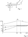
- Fig. 2 is shown in a diagram over time t, how the temperature T B of the bottom of the pot 18, namely at the top of the bottom, as well as the temperature T W of the water in the pot 18.
- the temperature T W of the water is an average temperature, since the water directly above the bottom of the pot will be slightly hotter than in the upper area. Such an inhomogeneous temperature distribution is common during heating.
- the temperature differences are a maximum of about 10 ° C to 20 ° C apart.
- the relative temperature profile S of the bottom of the pot 18 is plotted over time, as can be determined from the above-described operating parameters of the induction heating coil 15.
- a pot 18 placed on the induction hob 11 or the hotplate 16 is heated with water by the induction heating coil 15.
- the controller 20 specifies a high power density, for example a maximum boost power density of 10 W / cm 2 .
- a high power density for example a maximum boost power density of 10 W / cm 2 .
- the relative temperature profile S rises sharply, the pot bottom temperature T B also rises, albeit weaker.
- the temperature T W of the water rises only slowly.
- the bottom of the pot is especially important heated up, because only this can couple the heat into the water, which is naturally slower.
- the temperatures T B and T W run with an almost constant gradient and also almost parallel, the water temperature T W approaches the temperature curve T B somewhat.
- the averaged water temperature T W reaches a value of approximately 85 ° C.
- the bottom of the pot may already have reached a temperature of 100 ° C. a few seconds beforehand, which means that, as can be seen, this temperature cannot be exceeded while there is still water in the pot 18.
- the above-mentioned hold option for the hold time TH shown above of approximately 20 seconds is offered. The power density is greatly reduced to about 2 W / cm 2 to 3 W / cm 2 , so it is only 20% to 25%.
- the previous high power density can be set again after the hold time has expired, in this case the maximum boost power density.
- the power density can be increased again by the controller 20, but not to the maximum boost power density used at the beginning, but to a high power density, for example at 4 W / cm 2 to 6 W / cm 2 .
- the water in the pot is reheated to a final temperature of 100 ° C throughout, but this takes a little longer.
- Dash-dotted lines show the curve for the pot bottom temperature T B from the point in time of 300 seconds when the control 20 has reduced the power during the hold option. As a result of this reduction in output, the pot bottom temperature T B also drops somewhat, as shown in dotted lines. If the holding option is used, the power density remains low, so that in the long term, here for example from about 370 seconds, the pot bottom temperature T B has approached and is equal to the water temperature T W.
Landscapes
- Physics & Mathematics (AREA)
- Electromagnetism (AREA)
- Cookers (AREA)
Priority Applications (1)
| Application Number | Priority Date | Filing Date | Title |
|---|---|---|---|
| PL17192545T PL3307019T3 (pl) | 2016-10-10 | 2017-09-22 | Sposób eksploatacji indukcyjnej płyty grzejnej i indukcyjna płyta grzejna |
Applications Claiming Priority (1)
| Application Number | Priority Date | Filing Date | Title |
|---|---|---|---|
| DE102016219590.5A DE102016219590A1 (de) | 2016-10-10 | 2016-10-10 | Verfahren zum Betrieb eines Induktionskochfelds und Induktionskochfeld |
Publications (2)
| Publication Number | Publication Date |
|---|---|
| EP3307019A1 EP3307019A1 (de) | 2018-04-11 |
| EP3307019B1 true EP3307019B1 (de) | 2020-06-17 |
Family
ID=59930284
Family Applications (1)
| Application Number | Title | Priority Date | Filing Date |
|---|---|---|---|
| EP17192545.6A Active EP3307019B1 (de) | 2016-10-10 | 2017-09-22 | Verfahren zum betrieb eines induktionskochfelds und induktionskochfeld |
Country Status (7)
| Country | Link |
|---|---|
| US (1) | US10820381B2 (pl) |
| EP (1) | EP3307019B1 (pl) |
| KR (1) | KR102364282B1 (pl) |
| CN (1) | CN107920399B (pl) |
| DE (1) | DE102016219590A1 (pl) |
| ES (1) | ES2813587T3 (pl) |
| PL (1) | PL3307019T3 (pl) |
Families Citing this family (3)
| Publication number | Priority date | Publication date | Assignee | Title |
|---|---|---|---|---|
| DE102016224069A1 (de) * | 2016-12-02 | 2018-06-07 | E.G.O. Elektro-Gerätebau GmbH | Kochgerät mit einer Kochplatte und einer Heizeinrichtung darunter |
| EP3589077B1 (en) * | 2018-06-25 | 2021-02-24 | Electrolux Appliances Aktiebolag | Method for operating an induction hob and induction hob |
| CN112545296B (zh) * | 2019-09-25 | 2023-08-01 | 浙江苏泊尔家电制造有限公司 | 烹饪方法、烹饪器具及计算机存储介质 |
Family Cites Families (14)
| Publication number | Priority date | Publication date | Assignee | Title |
|---|---|---|---|---|
| DE19821439A1 (de) * | 1998-05-13 | 1999-11-18 | Bsh Bosch Siemens Hausgeraete | Sensorgesteuerte Garungseinheit mit Selbstkalibrierung |
| DE10329840A1 (de) | 2003-06-27 | 2005-01-20 | E.G.O. Elektro-Gerätebau GmbH | Verfahren und Vorrichtung zur Erkennung von Erwärmungsvorgängen |
| US7573005B2 (en) * | 2004-04-22 | 2009-08-11 | Thermal Solutions, Inc. | Boil detection method and computer program |
| ATE479316T1 (de) * | 2007-06-05 | 2010-09-15 | Miele & Cie | Verfahren zur kochfeldsteuerung und kochfeld zur durchführung des verfahrens |
| GB0711752D0 (en) * | 2007-06-18 | 2007-07-25 | Otter Controls Ltd | Electrical appliances |
| PL2312909T3 (pl) * | 2009-10-19 | 2015-10-30 | Whirlpool Co | Sposób sterowania zasilaniem w energię ciekłej zawartości naczynia do gotowania |
| JP2011090915A (ja) * | 2009-10-23 | 2011-05-06 | Panasonic Corp | 誘導加熱調理器及びそのプログラム |
| DE102009047185B4 (de) | 2009-11-26 | 2012-10-31 | E.G.O. Elektro-Gerätebau GmbH | Verfahren und Induktionsheizeinrichtung zum Ermitteln einer Temperatur eines mittels einer Induktionsheizspule erwärmten Kochgefäßbodens |
| EP2582203B1 (en) * | 2010-06-10 | 2017-08-30 | Panasonic Corporation | Induction cooker |
| DE102011083386A1 (de) * | 2011-09-26 | 2013-03-28 | E.G.O. Elektro-Gerätebau GmbH | Verfahren zum Beheizen eines Kochgefäßes mittels einer Induktionsheizeinrichtung und Induktionsheizeinrichtung |
| DE102011083383A1 (de) | 2011-09-26 | 2013-03-28 | E.G.O. Elektro-Gerätebau GmbH | Verfahren zum Beheizen einer in einem Kochgefäß enthaltenen Flüssigkeit und Induktionsheizeinrichtung |
| DE102011083397A1 (de) | 2011-09-26 | 2013-03-28 | E.G.O. Elektro-Gerätebau GmbH | Verfahren zum Zubereiten von Lebensmitteln mittels einer Induktionsheizeinrichtung und Induktionsheizeinrichtung |
| EP2741570B1 (en) * | 2012-12-04 | 2016-04-06 | Electrolux Home Products Corporation N.V. | A method and a control unit for controlling a cooking process on an induction cooking hob |
| EP2999301B1 (en) * | 2014-09-18 | 2019-03-06 | Electrolux Appliances Aktiebolag | Induction hob with boiling detection and induction energy control, method for heating food with an induction hob and computer program product |
-
2016
- 2016-10-10 DE DE102016219590.5A patent/DE102016219590A1/de not_active Withdrawn
-
2017
- 2017-09-22 PL PL17192545T patent/PL3307019T3/pl unknown
- 2017-09-22 ES ES17192545T patent/ES2813587T3/es active Active
- 2017-09-22 EP EP17192545.6A patent/EP3307019B1/de active Active
- 2017-10-06 US US15/727,122 patent/US10820381B2/en active Active
- 2017-10-06 KR KR1020170128558A patent/KR102364282B1/ko active Active
- 2017-10-10 CN CN201710934978.9A patent/CN107920399B/zh active Active
Non-Patent Citations (1)
| Title |
|---|
| None * |
Also Published As
| Publication number | Publication date |
|---|---|
| PL3307019T3 (pl) | 2020-11-30 |
| CN107920399B (zh) | 2021-12-31 |
| EP3307019A1 (de) | 2018-04-11 |
| US10820381B2 (en) | 2020-10-27 |
| CN107920399A (zh) | 2018-04-17 |
| US20180103511A1 (en) | 2018-04-12 |
| ES2813587T3 (es) | 2021-03-24 |
| KR20180039568A (ko) | 2018-04-18 |
| KR102364282B1 (ko) | 2022-02-16 |
| DE102016219590A1 (de) | 2018-04-12 |
Similar Documents
| Publication | Publication Date | Title |
|---|---|---|
| EP3267113B1 (de) | Verfahren zum betrieb eines kochfelds | |
| DE19906115C1 (de) | Verfahren zum Erkennen des Leerkochens von Geschirr bei Kochfeldern mit einer Glaskeramik-Kochfläche und zugehörige Vorrichtung | |
| DE3342416C1 (de) | Anordnung zum Steuern und Regeln der Heizleistung in der Aufheizphase eines Dampfdruckkochgefaesses | |
| DE69832329T2 (de) | Verfahren und Vorrichtung zur Regelung eines elektrischen Heizelementes | |
| DE3505232C1 (de) | Anordnung zum Steuern und Regeln der Heizleistung in der Aufheizphase eines Dampfdruckkochgefaesses | |
| EP3177107B1 (de) | Verfahren zum betrieb eines induktionskochfelds | |
| EP1378807A2 (de) | Verfahren zum Messen der Temperatur eines metallischen Kochgefässes | |
| EP3307019B1 (de) | Verfahren zum betrieb eines induktionskochfelds und induktionskochfeld | |
| EP1391141B1 (de) | Verfahren und vorrichtung zur begrenzung und/oder steuerung der oberflächentemperatur eines kochfelds | |
| DE3642181C1 (de) | Anordnung zum Beeinflussen der Gar- bzw. Kochzeit bei einem Kochgefaess | |
| DE3642180C2 (pl) | ||
| WO2001014798A1 (de) | Steuer- oder regeleinrichtung eines kochherdes | |
| CH669297A5 (de) | Verfahren zum steuern und regeln der heizleistung in der aufheizphase eines kochgefaesses. | |
| WO2009112150A2 (de) | Verfahren und vorrichtung zur steuerung eines kochfeldes | |
| DE4336752A1 (de) | Verfahren zum Anpassen der elektrischen Heizleistung an die zur Speisenzubereitung erforderlichen Kenngrößen | |
| DE3314398C2 (de) | Vorrichtung zur Steuerung des Gar- bzw. Kochvorganges in einem Kochgefäß | |
| DE102019107558A1 (de) | Verfahren zum Betrieb einer Kochstelle eines Kochfelds, vorzugsweise eines Induktionskochfelds, mit einem Kochgeschirr | |
| DE102019219808A1 (de) | Verfahren zum Betrieb eines Kochgeräts und Kochgerät | |
| EP3858203B1 (de) | Kochgeschirr, kochsystem und verfahren zum betreiben | |
| EP2789918B1 (de) | Verfahren zum Garen eines Garguts und Gargerät | |
| DE19726677B4 (de) | Verfahren zum Regeln der Wassertemperatur in einem Dampfgargerät sowie entsprechendes Dampfgargerät | |
| EP3136822B1 (de) | Verfahren zur temperaturbestimmung | |
| WO2016066542A1 (de) | Verfahren und vorrichtung zur steuerung eines behandlungsvorgangs | |
| EP1492385A2 (de) | Verfahren und Vorrichtung zur Erkennung von Erwärmungsvorgängen | |
| DE102016222313B4 (de) | Verfahren zum Kochen von mindestens einem Ei |
Legal Events
| Date | Code | Title | Description |
|---|---|---|---|
| PUAI | Public reference made under article 153(3) epc to a published international application that has entered the european phase |
Free format text: ORIGINAL CODE: 0009012 |
|
| STAA | Information on the status of an ep patent application or granted ep patent |
Free format text: STATUS: THE APPLICATION HAS BEEN PUBLISHED |
|
| AK | Designated contracting states |
Kind code of ref document: A1 Designated state(s): AL AT BE BG CH CY CZ DE DK EE ES FI FR GB GR HR HU IE IS IT LI LT LU LV MC MK MT NL NO PL PT RO RS SE SI SK SM TR |
|
| AX | Request for extension of the european patent |
Extension state: BA ME |
|
| STAA | Information on the status of an ep patent application or granted ep patent |
Free format text: STATUS: REQUEST FOR EXAMINATION WAS MADE |
|
| 17P | Request for examination filed |
Effective date: 20181008 |
|
| RBV | Designated contracting states (corrected) |
Designated state(s): AL AT BE BG CH CY CZ DE DK EE ES FI FR GB GR HR HU IE IS IT LI LT LU LV MC MK MT NL NO PL PT RO RS SE SI SK SM TR |
|
| STAA | Information on the status of an ep patent application or granted ep patent |
Free format text: STATUS: EXAMINATION IS IN PROGRESS |
|
| 17Q | First examination report despatched |
Effective date: 20190801 |
|
| GRAP | Despatch of communication of intention to grant a patent |
Free format text: ORIGINAL CODE: EPIDOSNIGR1 |
|
| STAA | Information on the status of an ep patent application or granted ep patent |
Free format text: STATUS: GRANT OF PATENT IS INTENDED |
|
| INTG | Intention to grant announced |
Effective date: 20200210 |
|
| GRAS | Grant fee paid |
Free format text: ORIGINAL CODE: EPIDOSNIGR3 |
|
| GRAA | (expected) grant |
Free format text: ORIGINAL CODE: 0009210 |
|
| STAA | Information on the status of an ep patent application or granted ep patent |
Free format text: STATUS: THE PATENT HAS BEEN GRANTED |
|
| AK | Designated contracting states |
Kind code of ref document: B1 Designated state(s): AL AT BE BG CH CY CZ DE DK EE ES FI FR GB GR HR HU IE IS IT LI LT LU LV MC MK MT NL NO PL PT RO RS SE SI SK SM TR |
|
| REG | Reference to a national code |
Ref country code: GB Ref legal event code: FG4D Free format text: NOT ENGLISH |
|
| REG | Reference to a national code |
Ref country code: CH Ref legal event code: EP |
|
| REG | Reference to a national code |
Ref country code: IE Ref legal event code: FG4D Free format text: LANGUAGE OF EP DOCUMENT: GERMAN |
|
| REG | Reference to a national code |
Ref country code: DE Ref legal event code: R096 Ref document number: 502017005714 Country of ref document: DE |
|
| REG | Reference to a national code |
Ref country code: AT Ref legal event code: REF Ref document number: 1282913 Country of ref document: AT Kind code of ref document: T Effective date: 20200715 |
|
| PG25 | Lapsed in a contracting state [announced via postgrant information from national office to epo] |
Ref country code: GR Free format text: LAPSE BECAUSE OF FAILURE TO SUBMIT A TRANSLATION OF THE DESCRIPTION OR TO PAY THE FEE WITHIN THE PRESCRIBED TIME-LIMIT Effective date: 20200918 Ref country code: LT Free format text: LAPSE BECAUSE OF FAILURE TO SUBMIT A TRANSLATION OF THE DESCRIPTION OR TO PAY THE FEE WITHIN THE PRESCRIBED TIME-LIMIT Effective date: 20200617 Ref country code: SE Free format text: LAPSE BECAUSE OF FAILURE TO SUBMIT A TRANSLATION OF THE DESCRIPTION OR TO PAY THE FEE WITHIN THE PRESCRIBED TIME-LIMIT Effective date: 20200617 Ref country code: FI Free format text: LAPSE BECAUSE OF FAILURE TO SUBMIT A TRANSLATION OF THE DESCRIPTION OR TO PAY THE FEE WITHIN THE PRESCRIBED TIME-LIMIT Effective date: 20200617 Ref country code: NO Free format text: LAPSE BECAUSE OF FAILURE TO SUBMIT A TRANSLATION OF THE DESCRIPTION OR TO PAY THE FEE WITHIN THE PRESCRIBED TIME-LIMIT Effective date: 20200917 |
|
| REG | Reference to a national code |
Ref country code: LT Ref legal event code: MG4D |
|
| REG | Reference to a national code |
Ref country code: NL Ref legal event code: MP Effective date: 20200617 |
|
| PG25 | Lapsed in a contracting state [announced via postgrant information from national office to epo] |
Ref country code: HR Free format text: LAPSE BECAUSE OF FAILURE TO SUBMIT A TRANSLATION OF THE DESCRIPTION OR TO PAY THE FEE WITHIN THE PRESCRIBED TIME-LIMIT Effective date: 20200617 Ref country code: LV Free format text: LAPSE BECAUSE OF FAILURE TO SUBMIT A TRANSLATION OF THE DESCRIPTION OR TO PAY THE FEE WITHIN THE PRESCRIBED TIME-LIMIT Effective date: 20200617 Ref country code: BG Free format text: LAPSE BECAUSE OF FAILURE TO SUBMIT A TRANSLATION OF THE DESCRIPTION OR TO PAY THE FEE WITHIN THE PRESCRIBED TIME-LIMIT Effective date: 20200917 Ref country code: RS Free format text: LAPSE BECAUSE OF FAILURE TO SUBMIT A TRANSLATION OF THE DESCRIPTION OR TO PAY THE FEE WITHIN THE PRESCRIBED TIME-LIMIT Effective date: 20200617 |
|
| PG25 | Lapsed in a contracting state [announced via postgrant information from national office to epo] |
Ref country code: AL Free format text: LAPSE BECAUSE OF FAILURE TO SUBMIT A TRANSLATION OF THE DESCRIPTION OR TO PAY THE FEE WITHIN THE PRESCRIBED TIME-LIMIT Effective date: 20200617 Ref country code: NL Free format text: LAPSE BECAUSE OF FAILURE TO SUBMIT A TRANSLATION OF THE DESCRIPTION OR TO PAY THE FEE WITHIN THE PRESCRIBED TIME-LIMIT Effective date: 20200617 |
|
| PG25 | Lapsed in a contracting state [announced via postgrant information from national office to epo] |
Ref country code: EE Free format text: LAPSE BECAUSE OF FAILURE TO SUBMIT A TRANSLATION OF THE DESCRIPTION OR TO PAY THE FEE WITHIN THE PRESCRIBED TIME-LIMIT Effective date: 20200617 Ref country code: PT Free format text: LAPSE BECAUSE OF FAILURE TO SUBMIT A TRANSLATION OF THE DESCRIPTION OR TO PAY THE FEE WITHIN THE PRESCRIBED TIME-LIMIT Effective date: 20201019 Ref country code: CZ Free format text: LAPSE BECAUSE OF FAILURE TO SUBMIT A TRANSLATION OF THE DESCRIPTION OR TO PAY THE FEE WITHIN THE PRESCRIBED TIME-LIMIT Effective date: 20200617 Ref country code: RO Free format text: LAPSE BECAUSE OF FAILURE TO SUBMIT A TRANSLATION OF THE DESCRIPTION OR TO PAY THE FEE WITHIN THE PRESCRIBED TIME-LIMIT Effective date: 20200617 Ref country code: SM Free format text: LAPSE BECAUSE OF FAILURE TO SUBMIT A TRANSLATION OF THE DESCRIPTION OR TO PAY THE FEE WITHIN THE PRESCRIBED TIME-LIMIT Effective date: 20200617 |
|
| PG25 | Lapsed in a contracting state [announced via postgrant information from national office to epo] |
Ref country code: SK Free format text: LAPSE BECAUSE OF FAILURE TO SUBMIT A TRANSLATION OF THE DESCRIPTION OR TO PAY THE FEE WITHIN THE PRESCRIBED TIME-LIMIT Effective date: 20200617 Ref country code: IS Free format text: LAPSE BECAUSE OF FAILURE TO SUBMIT A TRANSLATION OF THE DESCRIPTION OR TO PAY THE FEE WITHIN THE PRESCRIBED TIME-LIMIT Effective date: 20201017 |
|
| REG | Reference to a national code |
Ref country code: DE Ref legal event code: R097 Ref document number: 502017005714 Country of ref document: DE |
|
| REG | Reference to a national code |
Ref country code: ES Ref legal event code: FG2A Ref document number: 2813587 Country of ref document: ES Kind code of ref document: T3 Effective date: 20210324 |
|
| PLBE | No opposition filed within time limit |
Free format text: ORIGINAL CODE: 0009261 |
|
| STAA | Information on the status of an ep patent application or granted ep patent |
Free format text: STATUS: NO OPPOSITION FILED WITHIN TIME LIMIT |
|
| PG25 | Lapsed in a contracting state [announced via postgrant information from national office to epo] |
Ref country code: DK Free format text: LAPSE BECAUSE OF FAILURE TO SUBMIT A TRANSLATION OF THE DESCRIPTION OR TO PAY THE FEE WITHIN THE PRESCRIBED TIME-LIMIT Effective date: 20200617 |
|
| REG | Reference to a national code |
Ref country code: CH Ref legal event code: PL |
|
| 26N | No opposition filed |
Effective date: 20210318 |
|
| PG25 | Lapsed in a contracting state [announced via postgrant information from national office to epo] |
Ref country code: SI Free format text: LAPSE BECAUSE OF FAILURE TO SUBMIT A TRANSLATION OF THE DESCRIPTION OR TO PAY THE FEE WITHIN THE PRESCRIBED TIME-LIMIT Effective date: 20200617 |
|
| REG | Reference to a national code |
Ref country code: BE Ref legal event code: MM Effective date: 20200930 |
|
| PG25 | Lapsed in a contracting state [announced via postgrant information from national office to epo] |
Ref country code: LU Free format text: LAPSE BECAUSE OF NON-PAYMENT OF DUE FEES Effective date: 20200922 |
|
| PG25 | Lapsed in a contracting state [announced via postgrant information from national office to epo] |
Ref country code: BE Free format text: LAPSE BECAUSE OF NON-PAYMENT OF DUE FEES Effective date: 20200930 Ref country code: CH Free format text: LAPSE BECAUSE OF NON-PAYMENT OF DUE FEES Effective date: 20200930 Ref country code: IE Free format text: LAPSE BECAUSE OF NON-PAYMENT OF DUE FEES Effective date: 20200922 Ref country code: LI Free format text: LAPSE BECAUSE OF NON-PAYMENT OF DUE FEES Effective date: 20200930 |
|
| GBPC | Gb: european patent ceased through non-payment of renewal fee |
Effective date: 20210922 |
|
| PG25 | Lapsed in a contracting state [announced via postgrant information from national office to epo] |
Ref country code: TR Free format text: LAPSE BECAUSE OF FAILURE TO SUBMIT A TRANSLATION OF THE DESCRIPTION OR TO PAY THE FEE WITHIN THE PRESCRIBED TIME-LIMIT Effective date: 20200617 Ref country code: MT Free format text: LAPSE BECAUSE OF FAILURE TO SUBMIT A TRANSLATION OF THE DESCRIPTION OR TO PAY THE FEE WITHIN THE PRESCRIBED TIME-LIMIT Effective date: 20200617 Ref country code: CY Free format text: LAPSE BECAUSE OF FAILURE TO SUBMIT A TRANSLATION OF THE DESCRIPTION OR TO PAY THE FEE WITHIN THE PRESCRIBED TIME-LIMIT Effective date: 20200617 |
|
| PG25 | Lapsed in a contracting state [announced via postgrant information from national office to epo] |
Ref country code: MK Free format text: LAPSE BECAUSE OF FAILURE TO SUBMIT A TRANSLATION OF THE DESCRIPTION OR TO PAY THE FEE WITHIN THE PRESCRIBED TIME-LIMIT Effective date: 20200617 Ref country code: MC Free format text: LAPSE BECAUSE OF FAILURE TO SUBMIT A TRANSLATION OF THE DESCRIPTION OR TO PAY THE FEE WITHIN THE PRESCRIBED TIME-LIMIT Effective date: 20200617 |
|
| PG25 | Lapsed in a contracting state [announced via postgrant information from national office to epo] |
Ref country code: GB Free format text: LAPSE BECAUSE OF NON-PAYMENT OF DUE FEES Effective date: 20210922 |
|
| REG | Reference to a national code |
Ref country code: AT Ref legal event code: MM01 Ref document number: 1282913 Country of ref document: AT Kind code of ref document: T Effective date: 20220922 |
|
| PG25 | Lapsed in a contracting state [announced via postgrant information from national office to epo] |
Ref country code: AT Free format text: LAPSE BECAUSE OF NON-PAYMENT OF DUE FEES Effective date: 20220922 |
|
| PGFP | Annual fee paid to national office [announced via postgrant information from national office to epo] |
Ref country code: ES Payment date: 20241018 Year of fee payment: 8 Ref country code: IT Payment date: 20240930 Year of fee payment: 8 |
|
| PGFP | Annual fee paid to national office [announced via postgrant information from national office to epo] |
Ref country code: DE Payment date: 20250919 Year of fee payment: 9 |
|
| PGFP | Annual fee paid to national office [announced via postgrant information from national office to epo] |
Ref country code: PL Payment date: 20250909 Year of fee payment: 9 |
|
| PGFP | Annual fee paid to national office [announced via postgrant information from national office to epo] |
Ref country code: FR Payment date: 20250924 Year of fee payment: 9 |