EP3306968A1 - Verfahren, vorrichtung und system zur verarbeitung eines referenzsignals - Google Patents
Verfahren, vorrichtung und system zur verarbeitung eines referenzsignals Download PDFInfo
- Publication number
- EP3306968A1 EP3306968A1 EP17184482.2A EP17184482A EP3306968A1 EP 3306968 A1 EP3306968 A1 EP 3306968A1 EP 17184482 A EP17184482 A EP 17184482A EP 3306968 A1 EP3306968 A1 EP 3306968A1
- Authority
- EP
- European Patent Office
- Prior art keywords
- reference signal
- pilot position
- cell
- specified
- processing
- Prior art date
- Legal status (The legal status is an assumption and is not a legal conclusion. Google has not performed a legal analysis and makes no representation as to the accuracy of the status listed.)
- Withdrawn
Links
Images


Classifications
-
- H—ELECTRICITY
- H04—ELECTRIC COMMUNICATION TECHNIQUE
- H04L—TRANSMISSION OF DIGITAL INFORMATION, e.g. TELEGRAPHIC COMMUNICATION
- H04L5/00—Arrangements affording multiple use of the transmission path
- H04L5/003—Arrangements for allocating sub-channels of the transmission path
- H04L5/0048—Allocation of pilot signals, i.e. of signals known to the receiver
-
- H—ELECTRICITY
- H04—ELECTRIC COMMUNICATION TECHNIQUE
- H04B—TRANSMISSION
- H04B7/00—Radio transmission systems, i.e. using radiation field
- H04B7/02—Diversity systems; Multi-antenna system, i.e. transmission or reception using multiple antennas
- H04B7/022—Site diversity; Macro-diversity
- H04B7/024—Co-operative use of antennas of several sites, e.g. in co-ordinated multipoint or co-operative multiple-input multiple-output [MIMO] systems
-
- H—ELECTRICITY
- H04—ELECTRIC COMMUNICATION TECHNIQUE
- H04J—MULTIPLEX COMMUNICATION
- H04J11/00—Orthogonal multiplex systems, e.g. using WALSH codes
- H04J11/0023—Interference mitigation or co-ordination
- H04J11/005—Interference mitigation or co-ordination of intercell interference
- H04J11/0056—Inter-base station aspects
-
- H—ELECTRICITY
- H04—ELECTRIC COMMUNICATION TECHNIQUE
- H04L—TRANSMISSION OF DIGITAL INFORMATION, e.g. TELEGRAPHIC COMMUNICATION
- H04L5/00—Arrangements affording multiple use of the transmission path
- H04L5/003—Arrangements for allocating sub-channels of the transmission path
- H04L5/0032—Distributed allocation, i.e. involving a plurality of allocating devices, each making partial allocation
- H04L5/0035—Resource allocation in a cooperative multipoint environment
Definitions
- the present invention relates to the field of radio communications technologies, and in particular, to a method, an apparatus, and a system for processing a reference signal.
- an evolved NodeB In a radio communication system, in order to perform efficient radio resource scheduling, an evolved NodeB (eNB) must obtain sufficient and accurate downlink channel information. Currently, the information is obtained by means of measurement and reporting performed by a user equipment (UE).
- UE user equipment
- the method for measurement and reporting mainly includes: A serving eNB sends certain reference information to a served UE; after receiving the common reference signal (CRS), the served UE calculates and obtains downlink channel information through measurement; and the served UE properly quantizes the measured downlink channel information according to a rule and feeds back the quantized downlink channel information to the eNB.
- CRS common reference signal
- a CRS is defined in the prior art for the preceding method.
- CoMP coordinated multipoint transmission/reception
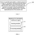
- FIG. 1 shows a scenario of a downlink radio communication system.
- This scenario includes Cell 1, Cell 2, Cell 3, and UE 1, where Cell 1 is a serving cell of UE 1, and Cell 1, Cell 2, and Cell 3 jointly form a CoMP set of UE 1.
- UE 1 performs a modulo operation according to a Cell 1-ID of the serving cell to calculate and obtain a pilot position of a CRS that is sent by an eNB to which Cell 1 belongs to UE 1, and UE 1 receives, in the CRS position, the CRS sent by the eNB to which Cell 1 belongs, measures and obtains the downlink channel information in Cell 1 according to the CRS, and then properly quantizes and feeds back the downlink channel information to the eNB to which Cell 1 belongs.
- this diagram represents reference signals in a downlink subframe of the eNB to which Cell 1 belongs, where a black block represents a sent CRS, a white block represents a data symbol, and a dashed-line block represents a sent reference signal for another purpose.
- the method in the prior art is unable to meet a requirement of enabling a UE to receive CRSs sent by eNBs to which multiple cells belong and accurately evaluate and obtain information about multiple downlink channels according to the CRSs.
- Embodiments of the present invention provide a method, an apparatus, and a system for processing a reference signal, which can meet a requirement of enabling a UE to measure downlink channels of multiple cells in a CoMP scenario.
- a method for processing a reference signal includes:
- a method for processing a reference signal includes:
- An apparatus for processing a reference signal includes:
- An apparatus for processing a reference signal includes:
- a system for processing a reference signal includes:
- the solutions to processing reference information according to the embodiments of the present invention have the following beneficial effects: Downlink reference signals of multiple cells are orthogonal to each other, so that the different reference signals of the multiple cells are prevented from colliding with each other; data puncturing are performed with respect to data symbols from another cell in positions corresponding to the specified pilot position, so that the interference from the data symbols of the another cell is avoided and measurement precision of the downlink channels of multiple cells is improved, thereby meeting the requirement of enabling a UE to measure downlink channels of multiple cells in a CoMP scenario.
- This embodiment provides a method for processing a reference signal, where the method is suitable for being deployed on a network side. As shown in FIG. 3 , the method includes:
- the specified pilot position is orthogonally separated from a reference signal pilot position of another cell in the CoMP set; and the another cell is a cell other than a cell corresponding to the specified pilot position. That is, the CoMP set consists of the cell corresponding to the specified pilot position and the another cell.
- this embodiment further provides an apparatus for processing a reference signal.
- the apparatus includes: a sending module 11 and a puncturing module 12.
- the sending module 11 is configured to send, in a specified pilot position, a reference signal to a target UE, where the specified pilot position is orthogonally separated from a reference signal pilot position of another cell in the CoMP set to which the UE belongs; and when the eNB to which the another cell in the CoMP set belongs sends respective data symbols, the puncturing module 12 is configured to perform data puncturing with respect to the sent data symbols, where a data-punctured position corresponds to at least one reference signal pilot position of another cell in the CoMP set.
- the method and apparatus for processing a reference signal according to this embodiment of the present invention adopt the following technical solution: Downlink reference signals of multiple cells are orthogonal to each other, and data puncturing is performed in the reference signal pilot position of another cell, which solves a technical problem of collision between reference signals of different cells in a CoMP scenario in the prior art, avoids interference of data symbols of the another cell, and improves measurement precision of downlink channels of multiple cells, thereby meeting a requirement of performing measurement of downlink channels of multiple cells in a CoMP scenario.
- This embodiment provides a method for processing a reference signal, where the method is suitable for being deployed on a user side. As shown in FIG. 5 , the method includes:
- the specified pilot position is orthogonally separated from a reference signal pilot position of the another cell; and the another cell is a cell other than a cell corresponding to the specified pilot position.
- Step 202 The UE detects, and measures according to the reference signal, a corresponding downlink channel, without performing data detection with respect to the data-punctured positions in the data symbols of the another cell.
- the UE For a data-punctured position, the UE considers that no data symbol is transmitted in this position, and a receiver of the UE does not perform data detection in this position, and therefore there is no problem of interference from the data symbols of the another cell.
- this embodiment further provides an apparatus for processing a reference signal, and specifically, the apparatus may be a UE.
- the apparatus may be a UE.
- the UE includes a receiving module 21 and a measuring module 22.
- the receiving module 21 is configured to receive a reference signal in a specified pilot position, where data puncturing are performed with respect to data symbols of another cell in a CoMP set that provides a service in positions corresponding to the specified pilot position, the specified pilot position is orthogonally separated from a reference signal pilot positions of the another cell, and the another cell is a cell other than a cell corresponding to the specified pilot position; and the measuring module 22 is configured to detect, and measure according to the reference signal received by the receiving module 21, a corresponding downlink channel, without detecting the data-punctured positions in the data symbols of the another cell.
- the method and apparatus for processing a reference signal have the following beneficial effects: Reference signals of multiple cells are orthogonally separated from each other, so that a problem of collision between different reference signals of multiple cells may be avoided, and meanwhile, because data puncturing is performed with respect to the reference signal pilot position of the another cell, the UE receives no interference from the data symbols of the another cell when receiving a signal. Therefore the following technical effects are achieved: Measurement precision of downlink channels is improved and the UE can measure downlink channels of multiple cells in a CoMP scenario.
- this embodiment specifically provides a method for processing a reference signal.
- the method relates to an eNB on a network side and a UE on a user side.
- Cell 1, Cell 2, and Cell 3, respectively corresponding to radio eNB 1, eNB 2, and eNB 3, and UE 1 are included.
- Cell 1 is a serving cell of UE 1
- Cell 1, Cell 2, and Cell 3 jointly form a CoMP set of UE 1.
- each of the cells in the formed CoMP set knows which CoMP set each of the cells belongs to, which cells are included in the CoMP set, and the served UE.
- the method specifically includes:
- a channel state information reference signal (CSI-RS) is specifically used as a reference signal.
- This reference signal is characterized by: a small overhead (the total overhead of up to 8 reference signals is less than 1% of downlink resources); and a long period (5 or 10 subframes). Therefore, in this embodiment, the reference signal is a CSI-RS and the reference signal pilot position is a CSI-RS pilot position.
- the reference signal pilot position that is negotiated in step 301 includes: a pilot time and a pilot coordinate of the reference signal.
- the pilot time includes: a pilot period (5 or 10 subframes) and an offset; and the pilot coordinate includes: an abscissa symbol and an ordinate subcarrier.
- step 301 may specifically be as follows: Assuming eNB 2 to which Cell 2 belongs will send a CSI-RS to UE 1, before that, eNB 2 needs to negotiate with eNB 1 and eNB 3 about respective CSI-RS pilot positions, and after the negotiation, the respective CSI-RS pilot positions are orthogonally separated in the time-frequency domain multiplexing mode. After obtaining its own reference signal pilot position through the negotiation, Cell 2 sends information including its own reference signal pilot position to eNB 1 to which Cell 1 belongs and eNB 2 to which Cell 2 belongs.
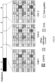
- the respective CSI-RS pilot positions of Cell 1, Cell 2, and Cell 3 after the negotiation are shown in FIG. 8 .
- the period of each cell is 5 subframes, and positions of ordinate subcarriers of the cells are the same, that is, the third and fourth, and the ninth and tenth positions. That is, the same subcarriers are used for transmission.
- the CSI-RS pilot position of Cell 1 is: Offset 1 (that is, the second subframe), a position of the tenth and eleventh symbols by abscissa;
- the CSI-RS pilot position of Cell 2 is: Offset 2 (that is, the third subframe), which is also the position of the tenth and eleventh symbols by abscissa;
- the CSI-RS pilot position of Cell 3 is: Offset 4 (that is, the fourth subframe), the position of the tenth and eleventh symbols by abscissa.
- the CRS pilot position in FIG. 8 is used for denoting that this part of resources has been occupied.
- other reference signals in FIG. 8 are all resources that have been in use in the prior art and are also used for denoting that this part of resources has been occupied in FIG. 8 of this embodiment.
- the respective CSI-RS pilot positions of Cell 1, Cell 2, and Cell 3 are orthogonally separated in time and frequency domains, so that it is ensured that CSI-RSs of different cells do not collide with each other, nor do the CSI-RSs interfere with each other. It should be pointed out that a long-period characteristic of the CSI-RS provides more mutually-orthogonal resources for accommodating the CSI-RSs of multiple cells and ensures that these CSI-RSs do not collide with each other.
- the CSI-RS pilot position of Cell 1 is a specified pilot position, and is also its own reference signal pilot position. Therefore, the pilot time and pilot coordinate of Cell 1 are the current pilot time and the current pilot coordinate.
- the CSI-RS of Cell 1 is the reference signal, and when eNB 2 sends the CSI-RS of Cell 2, eNB 1 to which Cell 1 belongs simultaneously sends a data symbol of Cell 1, and eNB 3 to which Cell 3 belongs simultaneously sends a data symbol of Cell 3.
- Step 302 The eNB to which the cell belongs notifies the UE served by the eNB of the reference signal pilot position of the cell, that is, the CSI-RS pilot position.
- eNB 2 to which Cell 2 belongs notifies UE 1 of the specified pilot position of Cell 2.
- the notification method may be any one of the following methods:
- step 301 and step 302 are not limited to the sequence described in this embodiment, and step 302 may be executed before step 301, or the two steps may even be executed simultaneously.
- Step 303 The UE obtains the CSI-RS pilot position of at least one cell.
- This step may specifically be that UE 1 obtains the CSI-RS pilot positions of Cell 1 and Cell 2 respectively.
- step 303 may specifically obtain the CSI-RS through the three methods as described in the following example.
- Cell 2 is taken as an example.
- First method Receive the Cell 2-ID, and perform a modulo operation with respect to the Cell2-ID to obtain the CSI-RS pilot position of Cell 2.
- the modulo operation procedure may specifically be similar to a procedure for obtaining a CRS pilot position according to a modulo operation with respect to the Cell 1-ID in the prior art, which is not repeatedly described here.
- Second method Receive the Cell2-ID and the virtual ID of Cell2 and obtain the CSI-RS pilot position of Cell2 by calculating the virtual ID and the Cell1-ID.
- the specific procedure may be: assuming that the received virtual ID of Cell 2 is 0 and that the Cell 2-ID is 4, the UE may find the CSI RS pilot position of Cell 2 by using the following operation:
- the reference signal pilot position of Cell2 is: in a period of 5 subframes, Offset2, the second position.
- Third method Receive high-layer signaling including the CSI-RS pilot position of Cell2 from eNB2.
- Step 301 to step 303 may be considered to be preparations before the eNB to which the cell belongs sends the CSI-RS.
- the reference signals are sent periodically, the CSI-RS pilot positions that are negotiated by the cells in the foregoing steps and the cell ID and virtual ID that are obtained by the UE and bound to each CSI-RS pilot position generally remain unchanged, and therefore do not need to be reset or changed with periodic sending of the CSI-RS.
- Step 304 The eNB to which the cell belongs sends, in the specified pilot position, the CSI-RS to the UE, and simultaneously, the eNB to which another cell in the same CoMP set belongs also sends respective data symbols, where data puncturing is performed with respect to the data symbols sent by each eNB in positions corresponding to the specified pilot position.
- the specified pilot position of the cell and the CSI-RS pilot position of the another cell is orthogonally separated in the time and frequency domains.
- step 304 may be: eNB 2 to which Cell 2 belongs sends a primary CSI-RS in the specified pilot position, and at the same time, eNB 1 to which Cell 1 belongs sends a data symbol, where data puncturing is performed with respect to the data symbol of Cell 1 in a position corresponding to the specified pilot position of Cell 2, and likewise, eNB 3 to which Cell 3 belongs sends a data symbol at the same time, where data puncturing is performed with respect to the data symbol of Cell 3 in a position corresponding to the specified pilot position of Cell 2.
- FIG. 9 The foregoing description may be represented by FIG. 9 .
- Step 305 The UE receives, in the specified pilot position, the CSI-RS from the corresponding cell, and measures a corresponding downlink channel according to the CSI-RS, without performing data detection with respect to the data-punctured positions in the data symbols.
- the UE For a data-punctured pilot position, the UE considers that no data symbol is transmitted in this position, and a receiver of the UE does not perform data detection in this position, and therefore there is no problem of interference from data symbols of the another cell.
- step 305 may be: UE 1 receives, in the specified pilot position, the CSI-RS from eNB 2, the data-punctured data symbol from eNB 1, and the data-punctured data symbol from eNB 3.
- UE 1 measures the downlink channel of Cell 2 according to the primary CSI-RS, and the receiver of UE 1 does not perform data detection with respect to the data-punctured positions in the data symbols of Cell 1 and Cell 3, so that there is no interference from data symbols of Cell 1 and Cell 3 when the downlink channel of Cell 2 is measured.
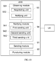
- this embodiment further provides an eNB to facilitate implementation of the part of the foregoing method relating to the network side.
- the eNB includes: a sending module 91 and a puncturing module 92.
- the sending module 91 is configured to send, in a specified pilot position, a reference signal to a target UE, where the specified pilot position is orthogonally separated from a reference signal pilot position of another cell in a CoMP set to which the UE belongs; and the puncturing module 92 is configured to perform data puncturing with respect to a sent data symbol, where a data-punctured position corresponds to at least one reference signal pilot position of the another cell in the CoMP set.
- the eNB in this embodiment also includes the following optional modules: an obtaining module 93 and a notifying module 94.
- the obtaining module 93 is configured to obtain a reference signal pilot position of another cell in the CoMP set; and the notifying module 94 is configured to notify the target UE of the specified pilot position.
- the obtaining module 93 includes: a negotiating unit 931 and a notifying unit 932.
- the negotiating unit 931 is configured to negotiate with the eNB to which another cell in the CoMP set belongs about the reference signal pilot positions, where the reference signal pilot positions of the cells after the negotiation are orthogonally separated in the time-frequency domain multiplexing mode; and the notifying unit 932 is configured to send information including the reference signal pilot position of the cell to the eNBs to which another cell in the CoMP set belongs.
- the specified pilot position is: the reference signal pilot position of the cell after the negotiation performed by the negotiating unit 931.
- the notifying module 94 includes at least one of the following units: a first sending unit 941, a second sending unit 942, and a third sending unit 943.
- the first sending unit 941 is configured to send information including a cell ID to the target UE, where the cell ID is bound to the specified pilot position;
- the second sending unit 942 is configured to send information including a cell ID and a virtual ID that is related to the common feature of the CoMP set to the target UE, where the cell ID and the virtual ID are bound to the specified pilot position;
- the third sending unit 943 is configured to send high-layer signaling including the specified pilot position to the target UE.
- the reference signal mentioned in the foregoing modules is a CSI-RS;
- the specified pilot position in the foregoing modules includes: the current pilot time and the current pilot coordinate;
- the reference signal pilot position in the foregoing modules includes: the pilot time and the pilot coordinate.
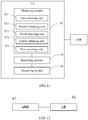
- this embodiment further provides a UE to facilitate implementation of the part relating to the user side in the foregoing method.
- the UE includes: a receiving module 95 and a measuring module 96.
- the receiving module 95 is configured to receive a reference signal in a specified pilot position, where data puncturing is performed with respect to data symbols of another cell in a CoMP set that provides a service in positions corresponding to the specified pilot position, and the specified pilot position is orthogonally separated from a reference signal pilot position of the another cell; and the measuring module 96 is configured to detect, and measure according to the reference signal received by the receiving module 95, a corresponding downlink channel, without detecting the data-punctured positions of the data symbols of the another cell.
- the another cell is a cell other than a cell corresponding to the specified pilot position.
- this embodiment also includes the following optional module: an obtaining module 97.
- the obtaining module 97 is configured to obtain a reference signal pilot position of at least one cell, where the at least one cell belongs to the CoMP set that provides the service.
- the obtaining module 97 includes: a first obtaining unit 971 and a second obtaining unit 972.
- the first obtaining unit 971 is configured to obtain a cell ID of at least one cell; and the second obtaining unit 972 is configured to obtain at least one corresponding reference signal pilot position by performing a modulo operation with respect to the cell ID;
- the specified pilot position is: any reference signal pilot position, in which a reference signal is received currently, among the at least one reference signal pilot position obtained by the second obtaining unit 972.
- the obtaining module 97 includes only a third obtaining unit 973 and a fourth obtaining unit 974; or the obtaining module 97 also includes a third obtaining unit 973 and a fourth obtaining unit 974.
- the third obtaining unit 973 is configured to obtain a cell ID of at least one cell and a virtual ID that is related to the common feature of the CoMP set; and the fourth obtaining unit 974 is configured to obtain at least one corresponding reference signal pilot position by performing a calculation with respect to the at least one pair of virtual ID and cell ID.
- the specified pilot position is: any reference signal pilot position, in which a reference signal is received currently, among the at least one reference signal pilot position obtained by the fourth obtaining unit 974.
- the obtaining module 97 includes only a first receiving unit 975; or the obtaining module 97 also includes a first receiving unit 975 configured to receive at least one piece of high-layer signaling including a reference signal pilot position.
- the specified pilot position is: any reference signal pilot position, in which a reference signal is received currently, among the at least one reference signal pilot position received by the first receiving unit 975.
- the reference signal mentioned in the foregoing modules is a CSI-RS;
- the specified pilot position in the foregoing modules includes: the current pilot time and the current pilot coordinate;
- the reference signal pilot position in the foregoing modules includes: the pilot time and the pilot coordinate.
- the solution according provided in this embodiment of the present invention has the following beneficial effects: A technical problem that the UE can obtain only the reference signal pilot position according to the cell ID of the serving cell in the prior art is solved; in the solution of this embodiment, the UE may obtain the reference signal pilot positions of all cells in the CoMP set that serves the UE, so the UE may also obtain the reference signals of multiple cells and measure corresponding downlink channels according to the reference signals; the downlink reference signals of multiple cells are orthogonal to each other, so that collision between different reference signals of multiple cells may be avoided; data puncturing is performed in the reference signal pilot position of the another cell, so that the interference from the data symbols of the another cell is avoided and thereby measurement precision of the downlink channels of multiple cells is improved, which meets a requirement of enabling the UE to measure downlink channels of multiple cells in a CoMP scenario.
- This embodiment provides a system for processing a reference signal.
- the system includes: an eNB 41 and a UE 42.
- the eNB 41 is configured to send, in a specified pilot position, a reference signal to a target UE 42, where the specified pilot position is orthogonally separated from a reference signal pilot position of another cell in a CoMP set to which UE 42 belongs; and the eNB 41 is also configured to perform data puncturing with respect to a sent data symbol, where a data-punctured position corresponds to at least one reference signal pilot position of the another cell in the CoMP set.
- the UE 42 is configured to receive, in the specified pilot position, the reference signal from the eNB 41, where data puncturing is performed with respect to the data symbols of the another cell in the CoMP providing services in positions corresponding to the specified pilot position; and detect, and measure according to the reference signal, a corresponding downlink channel, without detecting the data-punctured positions in the data symbols of the another cell.
- the another cell is a cell other than a cell corresponding to the specified pilot position.
- the system for processing a reference signal adopts the following technical solution: Reference signals of multiple cells are orthogonally separated and data puncturing is performed with respect to the reference signal pilot position of the another cell, which solves technical problems that different reference signals of multiple cells collide and interfere with each other and that the UE does not receive interference from data symbols of the another cell when receiving a signal in the prior art, and thereby achieves technical effects of improving measurement precision of downlink channels and enabling the UE to measure downlink channels of multiple cells in a CoMP scenario.
- This embodiment provides a system for processing a reference signal.
- the system includes: an eNB and a UE.
- the eNB has 8 CSI-RS ports in total.
- the eNB divides the 8 CSI-RS ports into two parts, where each part includes 4 CSI-RS ports and each port sends, in a specified pilot position, a CSI RS pilot signal to the target UE with a pilot period of 5 subframes (that is, the period for each port to send its CSI-RS is the same as a pilot period), and the pilot position used by each CSI-RS port for sending its CSI-RS may be notified to the UE by binding to the cell ID (in this embodiment, the pilot position is the second subframe in the 5-subframe period).
- the two parts of CSI-RS ports send respective CSI-RSs at intervals, that is, for any one of the CSI-RS ports, an actual period for sending a corresponding CSI-RS becomes 10 subframes.
- Cell 1 is taken as an example, and it is assumed that an eNB to which Cell 1 belongs is the eNB in this embodiment.
- the eNB is configured to send, in the specified pilot position, CSI-RSs corresponding to first 4 CSI-RS ports through the first 4 CSI-RS ports in the first pilot period (that is, the first 5 subframes), and the eNB is also configured to send, in the specified pilot position, CSI-RSs corresponding to subsequent 4 CSI-RS ports through the subsequent 4 CSI-RS ports in the second pilot period.
- the CSI-RSs are sent alternately and cyclically like this, where in any pilot period, the specified pilot position is orthogonally separated from a reference signal pilot position of another cell in the CoMP set to which the UE belongs; and the eNB is also configured to perform data puncturing with respect to a sent data symbol, where a data-punctured position corresponds to at least one reference signal pilot position of another cell in the CoMP set.
- the UE is configured to receive, in the specified pilot position, the CSI-RSs from the first 4 CSI-RS ports of the eNB in the first pilot period, and receive, in the specified pilot position, the CSI-RSs from the subsequent 4 CSI-RS ports of the eNB in the second pilot period. In this way, required CSI-RSs may be received alternately and cyclically.
- data puncturing is performed with respect to the data symbols of the another cell in the CoMP that provides a service in positions corresponding to the specified pilot position.
- the UE is configured to detect, and measure according to the reference signal, a corresponding downlink channel, without detecting the data-punctured positions in the data symbols of the another cell.
- the eNB has 8 CSI-RS ports in total, and the eNB divides the 8 CSI-RS ports into two parts according to a period: The first part is CSI-RS ports sending CSI-RSs with a period of 5 subframes, and the other part is CSI-RS ports sending CSI RS with a period of 10 subframes. Both the two parts send, in the specified pilot position, CSI RS pilot signals to the target UE, and the pilot period of the cell is still 5 subframes.
- the first 4 CSI-RS ports take 5 subframes as a period, 6 resource elements (REs) are occupied in one pilot period, and 4 REs are occupied in a next pilot period, where an RE is a minimum block in FIG. 8 ; the subsequent 4 CSI-RS ports take 10 subframes as a period, and 6 REs are occupied in each pilot period.
- the CSI-RS ports detected in each pilot period are different, so the UE needs to be notified of which resources are used to send the reference signals in each pilot period.
- Cell 1 is taken as an example, and it is assumed that the eNB to which Cell 1 belongs is the eNB in this embodiment.
- the eNB is configured to send, in the specified pilot position, CSI-RSs corresponding to 8 CSI-RS ports through the 8 CSI-RS ports in the first pilot period (that is, the first 5 subframes), and the eNB is also configured to send, in the specified pilot position, CSI-RSs corresponding to subsequent 4 CSI-RS ports through the subsequent 4 CSI-RS ports in the second pilot period.
- the CSI-RSs are sent alternately and cyclically like this, where in any pilot period, the specified pilot position is orthogonally separated from a reference signal pilot position of another cell in the CoMP set to which the UE belongs; and the eNB is also configured to perform data puncturing with respect to a sent data symbol, where a data-punctured position corresponds to at least one reference signal pilot position of the another cell in the CoMP set.
- the UE is configured to receive, in the specified pilot position, the CSI-RSs from the 8 CSI-RS ports of the eNB in the first pilot period, and receive, in the specified pilot position, the CSI-RSs from the subsequent 4 CSI-RS ports of the eNB in the second pilot period. In this way, the required CSI-RSs may be received alternately and cyclically.
- data puncturing is performed with respect to the data symbols of the another cell in the CoMP set that provides the service in positions corresponding to the specified pilot position.
- the UE is configured to detect, and measure according to the reference signal, a corresponding downlink channel, without detecting the data-punctured positions in the data symbols of the another cell.
- the system for processing a reference signal provided in this embodiment solves technical problems that different reference signals of multiple cells collide and interfere with each other and that the UE receives interference from data symbols of the another cell when receiving a signal in the prior art, and thereby achieves technical effects of improving measurement precision of downlink channels and enabling the UE to measure downlink channels of multiple cell in a CoMP scenario.
- reference signal ports use different periods to send respective reference signals, which solves a technical problem of a large overhead that is caused by that the reference signals are sent through multiple reference signal ports in one pilot period in the prior art.
- the present invention may be implemented by software and a necessary general hardware platform, or by hardware only, but the former is preferred in many cases.
- the technical solutions of the present invention, or the portions contributing to the prior art may be embodied in the form of a software product.
- the computer software product is stored in a readable storage medium, such as a floppy disk, a hard disk, or a Compact Disk-Read Only Memory (CD-ROM) of a computer, and includes several instructions to instruct a device (which may be a radio network controller) to execute the method described in each embodiment of the present invention.
- a device which may be a radio network controller
- Embodiment 1 A method for processing a reference signal, comprising:
- Embodiment 2 The method for processing a reference signal according to Embodiment 1, wherein the method further comprises:
- Embodiment 3 The method for processing a reference signal according to Embodiment 2, wherein the obtaining the reference signal pilot position of the another cell in the CoMP set is:
- Embodiment 4 The method for processing a reference signal according to Embodiment 1, wherein the method further comprises:
- Embodiment 5 The method for processing a reference signal according to Embodiment 4, wherein the notifying the target UE of the specified pilot position is:
- Embodiment 6 The method for processing a reference signal according to any one of Embodiments 1 to 5, wherein the reference signal is a channel state information reference signal; the specified pilot position comprises: a current pilot time and a current pilot coordinate; and the reference signal pilot position comprises: a pilot time and a pilot coordinate.
- Embodiment 7 A method for processing a reference signal, comprising:
- Embodiment 8 The method for processing a reference signal according to Embodiment 7, wherein the method further comprises:
- Embodiment 9 The method for processing a reference signal according to Embodiment 8, wherein the obtaining the reference signal pilot position of at least one cell comprises:
- Embodiment 10 The method for processing a reference signal according to any one of Embodiments 7 to 9, wherein the reference signal is a channel state information reference signal; the specified pilot position comprises: a current pilot time and a current pilot coordinate; and the reference signal pilot position comprises: a pilot time and a pilot coordinate.
- Embodiment 11 An apparatus for processing a reference signal, comprising:
- Embodiment 12 The apparatus for processing a reference signal according to Embodiment 11, wherein the apparatus further comprises:
- Embodiment 13 The apparatus for processing a reference signal according to Embodiment 12, wherein the obtaining module comprises:
- Embodiment 14 The apparatus for processing a reference signal according to Embodiment 11, wherein the apparatus further comprises:
- Embodiment 15 The apparatus for processing a reference signal according to Embodiment 14, wherein the notifying module comprises at least one of the following units:
- Embodiment 16 An apparatus for processing a reference signal, comprising:
- Embodiment 17 The apparatus for processing a reference signal according to Embodiment 16, wherein the apparatus further comprises:
- Embodiment 18 The apparatus for processing a reference signal according to Embodiment 17, wherein the obtaining module comprises:
- Embodiment 19 A system for processing a reference signal, comprising:
- Embodiment 20 The system for processing a reference signal according to Embodiment 19, wherein the apparatus for processing a reference signal sends the reference signal to the target UE through at least one reference signal port; the sending, by the apparatus for processing a reference signal, the reference signal in the specified pilot position to the target UE is: sending, by the apparatus for processing a reference signal, the reference signal in the specified pilot position through one part of reference signal ports among the at least one reference signal port; and another part of reference signal ports among the at least one reference signal port and the one part of reference signal ports send respective corresponding reference signals in different periods, and/or a period used for sending a reference signal by the other part of reference signal ports among the at least one reference signal port and a period used for sending a reference signal by the one part of reference signal ports are different in length.
Applications Claiming Priority (2)
| Application Number | Priority Date | Filing Date | Title |
|---|---|---|---|
| CN200910139568 | 2009-06-29 | ||
| EP10793597.5A EP2451202B1 (de) | 2009-06-29 | 2010-06-29 | Verfahren, vorrichtung und system zur verarbeitung von referenzsignalen |
Related Parent Applications (1)
| Application Number | Title | Priority Date | Filing Date |
|---|---|---|---|
| EP10793597.5A Division EP2451202B1 (de) | 2009-06-29 | 2010-06-29 | Verfahren, vorrichtung und system zur verarbeitung von referenzsignalen |
Publications (1)
| Publication Number | Publication Date |
|---|---|
| EP3306968A1 true EP3306968A1 (de) | 2018-04-11 |
Family
ID=43410493
Family Applications (2)
| Application Number | Title | Priority Date | Filing Date |
|---|---|---|---|
| EP17184482.2A Withdrawn EP3306968A1 (de) | 2009-06-29 | 2010-06-29 | Verfahren, vorrichtung und system zur verarbeitung eines referenzsignals |
| EP10793597.5A Active EP2451202B1 (de) | 2009-06-29 | 2010-06-29 | Verfahren, vorrichtung und system zur verarbeitung von referenzsignalen |
Family Applications After (1)
| Application Number | Title | Priority Date | Filing Date |
|---|---|---|---|
| EP10793597.5A Active EP2451202B1 (de) | 2009-06-29 | 2010-06-29 | Verfahren, vorrichtung und system zur verarbeitung von referenzsignalen |
Country Status (5)
| Country | Link |
|---|---|
| US (1) | US8879484B2 (de) |
| EP (2) | EP3306968A1 (de) |
| JP (1) | JP5527780B2 (de) |
| CN (1) | CN102388635B (de) |
| WO (1) | WO2011000302A1 (de) |
Families Citing this family (20)
| Publication number | Priority date | Publication date | Assignee | Title |
|---|---|---|---|---|
| US11223459B2 (en) | 2009-02-10 | 2022-01-11 | Telefonaktiebolaget Lm Ericsson (Publ) | Mapping user data onto a time-frequency resource grid in a coordinated multi-point wireless communication system |
| US8837396B2 (en) | 2009-02-10 | 2014-09-16 | Telefonaktiebolaget L M Ericsson (Publ) | Mapping user data onto a time-frequency resource grid in a coordinated multi-point wireless communication sytem |
| KR101754970B1 (ko) | 2010-01-12 | 2017-07-06 | 삼성전자주식회사 | 무선 통신 시스템의 채널 상태 측정 기준신호 처리 장치 및 방법 |
| WO2011122833A2 (en) | 2010-03-29 | 2011-10-06 | Lg Electronics Inc. | Method and apparatus for measurement for inter-cell interference coordination in radio communication system |
| US20120120846A1 (en) * | 2010-11-11 | 2012-05-17 | Mediatek Inc. | Methods for configuring channel state information measurement in a communications system and communications apparatuses utilizing the same |
| JP5749542B2 (ja) * | 2011-03-31 | 2015-07-15 | ソフトバンクモバイル株式会社 | 移動通信システム及び基地局装置 |
| WO2012147718A1 (ja) * | 2011-04-28 | 2012-11-01 | 三菱電機株式会社 | 通信システム |
| US8792924B2 (en) * | 2011-05-06 | 2014-07-29 | Futurewei Technologies, Inc. | System and method for multi-cell access |
| JP5914918B2 (ja) * | 2011-08-02 | 2016-05-11 | シャープ株式会社 | 基地局、端末および通信方法 |
| JP2013034111A (ja) | 2011-08-02 | 2013-02-14 | Sharp Corp | 基地局、端末、通信システムおよび通信方法 |
| JP5155431B1 (ja) * | 2011-10-03 | 2013-03-06 | 株式会社エヌ・ティ・ティ・ドコモ | 移動通信方法、無線基地局及び移動局 |
| WO2013055178A2 (ko) * | 2011-10-13 | 2013-04-18 | 엘지전자 주식회사 | 무선 통신 시스템에서 단말이 신호를 송수신하는 방법 및 이를 위한 장치 |
| CN104604160B (zh) | 2012-09-09 | 2018-10-30 | Lg电子株式会社 | 用于发送和接收数据的方法和设备 |
| CN102932850B (zh) * | 2012-11-05 | 2016-03-02 | 华为技术有限公司 | 基站、网络系统和通信方法 |
| US9014115B2 (en) * | 2012-11-23 | 2015-04-21 | Hitachi, Ltd. | Method and apparatus for handling downlink reference signal interference to PDSCH in long term evolution coordinated multipoint transmission |
| JP5883954B2 (ja) * | 2013-01-16 | 2016-03-15 | 株式会社日立製作所 | 無線通信方法 |
| KR20150106931A (ko) * | 2013-01-18 | 2015-09-22 | 노키아 솔루션스 앤드 네트웍스 오와이 | 휴면 모드에서 다수의 셀들로부터 기준 신호 송신 |
| US10517934B2 (en) * | 2014-08-25 | 2019-12-31 | ProTransit Nanotherapy, LLC | Compositions and methods for the treatment of photoaging and other conditions |
| CN115152266A (zh) * | 2020-03-04 | 2022-10-04 | 索尼集团公司 | 无线基站和无线终端 |
| CN113890707B (zh) * | 2021-09-26 | 2023-05-30 | 中国联合网络通信集团有限公司 | 通信方法、装置、设备以及存储介质 |
Family Cites Families (9)
| Publication number | Priority date | Publication date | Assignee | Title |
|---|---|---|---|---|
| US20020085641A1 (en) * | 2000-12-29 | 2002-07-04 | Motorola, Inc | Method and system for interference averaging in a wireless communication system |
| CN1921463B (zh) | 2005-08-23 | 2010-05-05 | 中兴通讯股份有限公司 | 正交频分复用移动通信系统的信道估计方法和实现装置 |
| EP2082598B1 (de) * | 2006-11-13 | 2018-04-18 | Telefonaktiebolaget LM Ericsson (publ) | Drahtlose telekommunikationssysteme |
| KR101307123B1 (ko) * | 2007-05-04 | 2013-09-10 | 삼성전자주식회사 | 직교 주파수 분할 다중 접속 시스템에서의 데이터 송수신방법 및 장치 |
| CN101340228B (zh) * | 2008-08-07 | 2014-05-28 | 中兴通讯股份有限公司南京分公司 | 一种参考信号的传输方法 |
| CN101340227B (zh) * | 2008-08-15 | 2012-10-10 | 中兴通讯股份有限公司 | 下行参考信号的发送方法和装置 |
| TWI504299B (zh) * | 2008-10-20 | 2015-10-11 | Interdigital Patent Holdings | 載波聚合上鏈控制資訊傳輸方法 |
| KR101619446B1 (ko) * | 2008-12-02 | 2016-05-10 | 엘지전자 주식회사 | 하향링크 mimo시스템에 있어서 rs 전송 방법 |
| CN101453438B (zh) * | 2008-12-11 | 2011-05-25 | 上海无线通信研究中心 | 提高多点协作传输效率的方法 |
-
2010
- 2010-06-29 EP EP17184482.2A patent/EP3306968A1/de not_active Withdrawn
- 2010-06-29 WO PCT/CN2010/074657 patent/WO2011000302A1/zh active Application Filing
- 2010-06-29 CN CN201080003641.2A patent/CN102388635B/zh active Active
- 2010-06-29 JP JP2012518015A patent/JP5527780B2/ja active Active
- 2010-06-29 EP EP10793597.5A patent/EP2451202B1/de active Active
-
2011
- 2011-12-29 US US13/340,337 patent/US8879484B2/en active Active
Non-Patent Citations (4)
| Title |
|---|
| "Joint Processing Downlink COMP Reference Signal Support", 3GPP DRAFT; R1-090586 TI COMP RS, 3RD GENERATION PARTNERSHIP PROJECT (3GPP), MOBILE COMPETENCE CENTRE ; 650, ROUTE DES LUCIOLES ; F-06921 SOPHIA-ANTIPOLIS CEDEX ; FRANCE, vol. RAN WG1, no. Athens, Greece; 20090212 - 20090216, 3 February 2009 (2009-02-03), XP050597221 * |
| ALCATEL-LUCENT SHANGHAI BELL ET AL: "Multi-cell cooperative RS in CoMP", 3GPP DRAFT; R1-092317 MULTI-CELL COOPERATIVE RS IN COMP, 3RD GENERATION PARTNERSHIP PROJECT (3GPP), MOBILE COMPETENCE CENTRE ; 650, ROUTE DES LUCIOLES ; F-06921 SOPHIA-ANTIPOLIS CEDEX ; FRANCE, no. Los Angeles, USA; 20090624, 24 June 2009 (2009-06-24), XP050350848 * |
| HUAWEI ET AL: "Further Discussions on the Downlink Coordinated Transmission - Impact on the Radio Interface", 3GPP DRAFT; R1-090129 FURTHER DISCUSSIONS ON DOWNLINK COORDINATED TRANSMISSION, 3RD GENERATION PARTNERSHIP PROJECT (3GPP), MOBILE COMPETENCE CENTRE ; 650, ROUTE DES LUCIOLES ; F-06921 SOPHIA-ANTIPOLIS CEDEX ; FRANCE, no. Ljubljana; 20090107, 7 January 2009 (2009-01-07), XP050318067 * |
| ZTE: "Resource Mapping Issues on JP transmission in CoMP", 3GPP DRAFT; R1-090070 RESOURCE MAPPING ISSUES ON JP TRANSMISSION IN COMP, 3RD GENERATION PARTNERSHIP PROJECT (3GPP), MOBILE COMPETENCE CENTRE ; 650, ROUTE DES LUCIOLES ; F-06921 SOPHIA-ANTIPOLIS CEDEX ; FRANCE, no. Ljubljana; 20090107, 7 January 2009 (2009-01-07), XP050318014 * |
Also Published As
| Publication number | Publication date |
|---|---|
| US20120099547A1 (en) | 2012-04-26 |
| US8879484B2 (en) | 2014-11-04 |
| WO2011000302A1 (zh) | 2011-01-06 |
| EP2451202B1 (de) | 2017-08-23 |
| JP2012531858A (ja) | 2012-12-10 |
| CN102388635B (zh) | 2014-10-08 |
| EP2451202A1 (de) | 2012-05-09 |
| CN102388635A (zh) | 2012-03-21 |
| EP2451202A4 (de) | 2012-09-19 |
| JP5527780B2 (ja) | 2014-06-25 |
Similar Documents
| Publication | Publication Date | Title |
|---|---|---|
| US8879484B2 (en) | Method, apparatus, and system for processing reference signal | |
| US10931419B2 (en) | Method and device for transmitting and receiving signals | |
| EP3522579B1 (de) | Steuerkanalübertragungs- und empfangsverfahren und system dafür | |
| EP3580884B1 (de) | Verfahren und vorrichtung zur konfiguration der demodulationsreferenzsignalposition in einem drahtlosen zellularen kommunikationssystem | |
| CN111245561B (zh) | 一种处理灵活子帧的上下行传输的方法和设备 | |
| CN104770039B (zh) | 用于先进的长期演进的传输模式10的物理下行共享信道的天线端口的传输方案和准协同定位假设 | |
| EP2472940B1 (de) | Verfahren und Vorrichtung zur Durchführung von Kanalmessungen für Zellen | |
| RU2573581C2 (ru) | Базовая станция, мобильный терминал и способ управления связью | |
| EP2826285B1 (de) | Verfahren und vorrichtungen zur interferenzkanalmessung in einem funknetzwerk | |
| EP2906005B1 (de) | Verfahren zur detektion einer steuerkanals sowie benutzervorrichtung und basisstation | |
| WO2012006931A1 (zh) | 一种csi-rs的发送方法、检测方法及其装置 | |
| EP3021608A1 (de) | Interferenzmessverfahren, system, zugehörige ausrüstung und speichermedium | |
| CN104584452A (zh) | 在回退情况下用于协作多点传输的下行链路数据的接收 | |
| US10070271B2 (en) | Method and system for configuring, sending and receiving physical multicast channel | |
| CN108702685B (zh) | 传输模式的信息的传输方法、网络设备、终端设备和系统 | |
| US20160028530A1 (en) | Method and Device for Sending ePHICH, and Method and Device for Receiving ePHICH | |
| EP2739114A1 (de) | Verfahren und vorrichtung zur durchführung einer synchronisation und erfassung zwischen benutzervorrichtungen | |
| WO2021057589A1 (zh) | 信号的发送、接收方法及终端 | |
| WO2018223891A1 (zh) | 参考信号的传输方法、装置和设备 | |
| CN109155711B (zh) | 参考信号发送方法、检测方法、基站和移动台 | |
| WO2013044659A1 (zh) | 一种数据资源映射位置的处理方法和装置 | |
| WO2016169203A1 (zh) | 一种信道探测方法、装置及系统 | |
| CN102821392A (zh) | 小区间干扰抑制的下行业务传输方法及装置 | |
| CN107113275A (zh) | 一种数据传输方法、装置和系统 |
Legal Events
| Date | Code | Title | Description |
|---|---|---|---|
| PUAI | Public reference made under article 153(3) epc to a published international application that has entered the european phase |
Free format text: ORIGINAL CODE: 0009012 |
|
| STAA | Information on the status of an ep patent application or granted ep patent |
Free format text: STATUS: THE APPLICATION HAS BEEN PUBLISHED |
|
| AC | Divisional application: reference to earlier application |
Ref document number: 2451202 Country of ref document: EP Kind code of ref document: P |
|
| AK | Designated contracting states |
Kind code of ref document: A1 Designated state(s): AL AT BE BG CH CY CZ DE DK EE ES FI FR GB GR HR HU IE IS IT LI LT LU LV MC MK MT NL NO PL PT RO SE SI SK SM TR |
|
| STAA | Information on the status of an ep patent application or granted ep patent |
Free format text: STATUS: REQUEST FOR EXAMINATION WAS MADE |
|
| 17P | Request for examination filed |
Effective date: 20180910 |
|
| RBV | Designated contracting states (corrected) |
Designated state(s): AL AT BE BG CH CY CZ DE DK EE ES FI FR GB GR HR HU IE IS IT LI LT LU LV MC MK MT NL NO PL PT RO SE SI SK SM TR |
|
| GRAP | Despatch of communication of intention to grant a patent |
Free format text: ORIGINAL CODE: EPIDOSNIGR1 |
|
| STAA | Information on the status of an ep patent application or granted ep patent |
Free format text: STATUS: GRANT OF PATENT IS INTENDED |
|
| INTG | Intention to grant announced |
Effective date: 20200225 |
|
| GRAS | Grant fee paid |
Free format text: ORIGINAL CODE: EPIDOSNIGR3 |
|
| STAA | Information on the status of an ep patent application or granted ep patent |
Free format text: STATUS: THE APPLICATION HAS BEEN WITHDRAWN |
|
| 18W | Application withdrawn |
Effective date: 20200423 |