EP3306579A1 - Unité de stockage de feuilles de papier et guichet automatique bancaire - Google Patents
Unité de stockage de feuilles de papier et guichet automatique bancaire Download PDFInfo
- Publication number
- EP3306579A1 EP3306579A1 EP16802881.9A EP16802881A EP3306579A1 EP 3306579 A1 EP3306579 A1 EP 3306579A1 EP 16802881 A EP16802881 A EP 16802881A EP 3306579 A1 EP3306579 A1 EP 3306579A1
- Authority
- EP
- European Patent Office
- Prior art keywords
- bill
- storage box
- protrusion
- paper sheet
- bills
- Prior art date
- Legal status (The legal status is an assumption and is not a legal conclusion. Google has not performed a legal analysis and makes no representation as to the accuracy of the status listed.)
- Pending
Links
Images


Classifications
-
- B—PERFORMING OPERATIONS; TRANSPORTING
- B65—CONVEYING; PACKING; STORING; HANDLING THIN OR FILAMENTARY MATERIAL
- B65H—HANDLING THIN OR FILAMENTARY MATERIAL, e.g. SHEETS, WEBS, CABLES
- B65H31/00—Pile receivers
- B65H31/24—Pile receivers multiple or compartmented, e.d. for alternate, programmed, or selective filling
-
- G—PHYSICS
- G07—CHECKING-DEVICES
- G07F—COIN-FREED OR LIKE APPARATUS
- G07F19/00—Complete banking systems; Coded card-freed arrangements adapted for dispensing or receiving monies or the like and posting such transactions to existing accounts, e.g. automatic teller machines
- G07F19/20—Automatic teller machines [ATMs]
- G07F19/202—Depositing operations within ATMs
-
- G—PHYSICS
- G07—CHECKING-DEVICES
- G07D—HANDLING OF COINS OR VALUABLE PAPERS, e.g. TESTING, SORTING BY DENOMINATIONS, COUNTING, DISPENSING, CHANGING OR DEPOSITING
- G07D11/00—Devices accepting coins; Devices accepting, dispensing, sorting or counting valuable papers
- G07D11/10—Mechanical details
- G07D11/12—Containers for valuable papers
-
- G—PHYSICS
- G07—CHECKING-DEVICES
- G07D—HANDLING OF COINS OR VALUABLE PAPERS, e.g. TESTING, SORTING BY DENOMINATIONS, COUNTING, DISPENSING, CHANGING OR DEPOSITING
- G07D11/00—Devices accepting coins; Devices accepting, dispensing, sorting or counting valuable papers
- G07D11/50—Sorting or counting valuable papers
-
- B—PERFORMING OPERATIONS; TRANSPORTING
- B65—CONVEYING; PACKING; STORING; HANDLING THIN OR FILAMENTARY MATERIAL
- B65H—HANDLING THIN OR FILAMENTARY MATERIAL, e.g. SHEETS, WEBS, CABLES
- B65H2402/00—Constructional details of the handling apparatus
- B65H2402/40—Details of frames, housings or mountings of the whole handling apparatus
- B65H2402/44—Housings
-
- B—PERFORMING OPERATIONS; TRANSPORTING
- B65—CONVEYING; PACKING; STORING; HANDLING THIN OR FILAMENTARY MATERIAL
- B65H—HANDLING THIN OR FILAMENTARY MATERIAL, e.g. SHEETS, WEBS, CABLES
- B65H2402/00—Constructional details of the handling apparatus
- B65H2402/40—Details of frames, housings or mountings of the whole handling apparatus
- B65H2402/45—Doors
-
- B—PERFORMING OPERATIONS; TRANSPORTING
- B65—CONVEYING; PACKING; STORING; HANDLING THIN OR FILAMENTARY MATERIAL
- B65H—HANDLING THIN OR FILAMENTARY MATERIAL, e.g. SHEETS, WEBS, CABLES
- B65H2405/00—Parts for holding the handled material
- B65H2405/10—Cassettes, holders, bins, decks, trays, supports or magazines for sheets stacked substantially horizontally
- B65H2405/11—Parts and details thereof
- B65H2405/115—Cover
-
- B—PERFORMING OPERATIONS; TRANSPORTING
- B65—CONVEYING; PACKING; STORING; HANDLING THIN OR FILAMENTARY MATERIAL
- B65H—HANDLING THIN OR FILAMENTARY MATERIAL, e.g. SHEETS, WEBS, CABLES
- B65H2405/00—Parts for holding the handled material
- B65H2405/30—Other features of supports for sheets
- B65H2405/33—Compartmented support
- B65H2405/332—Superposed compartments
Definitions
- the present invention relates to, for example, a paper sheet storage box mounted in a bill handling device such as incorporated in an ATM (Automatic Teller Machine) installed at financial facilities and the like, and to an automatic teller machine.
- a bill handling device such as incorporated in an ATM (Automatic Teller Machine) installed at financial facilities and the like
- an automatic teller machine for example, a paper sheet storage box mounted in a bill handling device such as incorporated in an ATM (Automatic Teller Machine) installed at financial facilities and the like.
- the bill handling machine is mounted in the automatic teller machine used in the financial facilities and the like.
- This bill handling device includes: a bill depositing and dispensing slot through which a user deposits or withdraws a bill or some bills; a bill determination portion which determines whether a bill is a deposited bill or a bill to be dispensed; a temporary storage box for temporarily storing the deposited bill(s) till the conclusion of a transaction; a bill storage box for receiving and storing the bill(s); and a bill conveyance passage for conveying the bill(s) to the above-described parts.
- the bill storage box includes: a recycle box which stores the bills deposited/dispensed by bill denomination; a loading box which replenishes the recycle box with the bills or collects the bills from the recycle box; a reject box which stores reject bills which are determined by the bill determination portion as falling short of the standards.
- the reject box is desirably composed of a plurality of chambers because the box may sometimes be adapted to store the reject bills as sorting them into a bill rejected at deposition/reception; a bill rejected at dispensation; a bill left by the customer; and the like. There may be a case where folded bills or crumpled bills are stored. Therefore, it is imperative to reliably sort out such bills before storage. The smaller in size, the better is the bill handling device. It is therefore desirable that the reject box is also downsized as much as possible.
- the above patent literature 1 proposes an operation where the reject box is divided into plural box portions such that, for example, an upper reject box portion stores bogus bills while a lower reject box portion stores bills which do not include the bogus bills but those to be stored separately from acceptable bills.
- a reject box requires a partition plate for perfectly dividing the box into the upper and lower portions because the upper and lower portions must be reliably separated.
- this reject box has a problem that when the bills are extracted from the reject box, the partition plate interferes with a bill extraction operation, resulting in the decrease in bill extraction handleability.
- the invention has an object to provide a paper sheet storage box which permits a storage space thereof to be partitioned while maintaining good bill handleability, and an automatic teller machine using the same.
- a paper sheet storage box includes: a partition member which partitions a paper sheet storage space into a plurality of storage spaces and includes a recess at a position for extraction of the paper sheets; and a door which includes a protrusion located at a position corresponding to the recess so as to close the recess, and serves to open or close an opening including the plurality of storage spaces.
- the invention permits the storage space to be partitioned while maintaining good bill handleability.
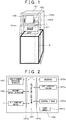
- FIG. 1 is a perspective view showing an external appearance of an automatic teller machine 101.
- an automatic teller machine 101 includes a machine housing 101b.
- An upper part of the machine housing 101b contains therein: a customer operation portion 105 on the left side; and a card/statement processing mechanism 102 on the right side.
- the customer operation portion 105 displays the contents of transaction and accepts input.
- the card/statement processing mechanism 102 is communicated with a card slot 102a formed in an upper front panel 101a so as to process a card of a user and to output a printed account statement.
- the upper front panel 101a of the automatic teller machine 101 is provided with a bill depositing/dispensing slot (bill slot) 21.
- the automatic teller machine 101 contains therein a bill handling device 1 for processing bills.
- the bill handling device 1 other than the bill depositing/dispensing slot is enclosed by a vault housing A which is independent from the machine housing 101b and is made of a thick iron plate having a thickness of tens of millimeters.
- Fig. 2 is a control block diagram showing control relations of the automatic teller machine 101.
- the card/statement processing mechanism 102, the bill handling device 1 and the customer operation portion 105 housed in the automatic teller machine 101 are connected to a main body controller 107 via a bus 107a, performing required operations under the control of the main body controller 107.
- the main body controller 107 is also connected with an interface 107b, a staff operation portion 107c and an external storage 107d via the bus 107a, sending or receiving required data.
- a component 101e shown in Fig. 2 is a power supply for supplying an electric power to the above mechanism and components.
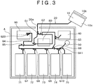
- Fig. 3 is a sectional view of the bill handling device 1.
- the bill handling device 1 includes: a bill depositing/dispensing slot 10; a conveyance passage 20; a conveyance passage 30; a determination portion 80; a temporary storage box 40; a return-bill temporary storage box 50; storage boxes 71 to 75; and a collection box 90.
- the bill depositing/dispensing slot 10 and the conveyance passage 20 are disposed on a top side of a vault A.
- the other components are disposed in the vault A.
- the bill depositing/dispensing slot 10 is provided to permit the user to deposit or withdraw some bills.
- the bill depositing/dispensing slot 10 includes a pocket 10a and a shutter 10b.
- the pocket 10a defines a space for the bill to be placed in a position inclined relative to the horizontal plane.
- the conveyance passage 20 and the conveyance passage 30 are for conveyance of the bills.
- the conveyance of the bills is performed by using known rollers (not shown) and the like.
- the determination portion 80 determines the denomination and the authenticity of the bill carried in both directions and decides whether to return or receive the deposited bill based on a determination result.
- the temporary storage box 40 temporarily stores bill(s) deposited by the user till the conclusion of a transaction.
- the return-bill temporary storage box 50 temporarily stores any bill, out of those deposited, that is determined to be unacceptable.
- the storage boxes 71 to 75 store the bills on a per-bill denomination basis.
- the storage box 74 or the storage box 75 may also be used as a storage box for storing bills to be deposited or bills to be dispensed.
- the storage box 75 is used as the storage box for this purpose.
- the collection box 90 is used for collecting the bogus bills or storing the bills left by the user.
- Fig. 4 shows control blocks of the bill handling device 1.
- the bill handling device 1 includes a control unit 16 not shown in Fig. 1 .
- the control unit 16 includes: a main controller 161; a memory 162; and a higher-order communication portion 163.
- the main controller 161 controls the operations of the above-described components shown in Fig. 1 or acquires information pieces (such as the number of stored bills) sent form sensors of the components.
- the main controller 161 communicates with an ATMPC 200 as an external device via the higher-order communication portion 163.
- the conveyance passages 20, 30 include a plurality of turnouts G1 to G11, detection sensors 165 and drive motors 166 (the details of which will be described hereinlater).
- the conveyance passage 30 is a generic term of conveyance passages 30a to 301, the details of which will be described hereinlater.
- a turnout 164 (hereinafter, referred to as G1 to G11, G20, G30) is disposed at a branching point so as to decide to which of the branch destinations the bill is conveyed.
- the turnout is operated by an electromagnetic solenoid or the like.
- the detection sensor 165 outputs detection signals related to bill passage and conveyance abnormality.
- the drive motor 166 rotates to convey the bill.
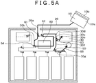
- Fig. 5A and Fig. 5B are diagrams illustrating a received bill counting process performed by the bill handling device 1.
- the received bill counting process includes authenticity determination, denomination determination, and counting of bills thrown into the pocket 10a of the bill depositing/dispensing slot 10.
- the control unit 16 delivers the bills in the pocket 10a one by one into the conveyance passage 30 via the conveyance passage 20.
- the control unit 16 connects a conveyance passage 30a with a conveyance passage 30b by means of the turnout G1 in order to transfer the bill to the conveyance passage 30b and then, connects the conveyance passage 30b with the determination portion 80 by means of the turnout G4.
- the determination portion 80 acquires an image of the bill by means of a sensor mounted in the determination portion 80 so as to determine the authenticity, the denomination and an intact condition (damaged condition) of the bill.
- the control unit 16 conveys the bill via a conveyance passage 30c.
- the determination by the determination portion 80 is completed while the bill is conveyed through this conveyance passage.
- the control unit 16 switches a turnout G3 according to the determination result. Specifically, if the bill is determined to be acceptable, the control unit 16 connects a conveyance passage 30d with a conveyance passage 30e by means of the turnout G3. As a result, the bill is temporarily stored in the temporary storage box 40.
- the control unit 16 connects the conveyance passage 30d with a conveyance passage 30f by means of the turnout G3 and connects the conveyance passage 30f with a conveyance passage 30g via a turnout G6. Consequently, the bill passes through the conveyance passage 30g to be stored in the return-bill temporary storage box 50. If the bill is stored in the return-bill temporary storage box 50, the control unit 16 discharges all the bills placed in the pocket 10a and thereafter, return the bill in question to the determination portion 80 by means of turnouts G6, G5, G4 and conveyance passages 30g, 30h, 30i, as shown in Fig. 5B . Accordingly, the bill in question is judged again by the determination portion 80.
- the control unit 16 stores the bill in the temporary storage box 40, as described above. On the other hand, the control unit 16 returns the bill determined again to be unacceptable to the bill depositing/dispensing slot 10 by means of the turnouts G1, G2 and the conveyance passages 30K 30a. In this manner, the risk of accidentally returning the acceptable bill is reduced by reloading the image of the bill once determined to be unacceptable.
- the control unit 16 displays the total monetary amount of the bills stored in the temporary storage box 40 by means of an indicator.
- the control unit 16 stores the bills temporarily stored in the temporary storage box 40 in the storage boxes 71 to 75 to be described as below (received bill storage process).
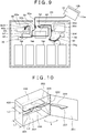
- the received bill storage process is described with reference to Fig. 6 .
- the control unit 16 conveys the bill to a lower part by means of the turnouts G3, G2, G4, G5 and the conveyance passages 30e, 30c, 30i, 30h.
- the control unit 16 selectively delivers the bill to any one of the storage boxes 71 to 75 as the bill destination by using any one of the turnouts G7 to G11.
- Fig. 7 is a diagram illustrating a dispensed bill dealing process performed by the bill handling device 1.
- the control unit 16 discharges the bills one by one from the storage boxes 71 to 74 which store the bills by bill denomination. Subsequently, the control unit 16 delivers the discharged bill to the determination portion 80 via the conveyance passages 30h, 30i.
- the determination portion 80 determines whether the delivered bill is dispensable or not. If the bill is determined to be dispensable, the control unit 16 connects the conveyance passage 30c with the conveyance passage 30k by means of the turnout G2. Subsequently, the control unit 16 conveys the bill to the pocket 10a by means of the conveyance passage 30a and the conveyance passage 20.
- the control unit 16 connects the conveyance passage 30c with the conveyance passage 30d by means of the turnout G2. Subsequently, the control unit 16 conveys the bill via the conveyance passages 30f, 30g so as to store the bill in the storage box 75. The determination of the bill at the time of bill dispensation and the switching of the turnout G2 based on the determination result are completed before the bill arrives at the turnout G2. After all the bills to be dispensed are delivered to the pocket 10a, the control unit 16 opens the shutter 10b. When the user takes away the bills placed in the pocket 10a, the control unit 16 closes the shutter 10b, thus completing the dispensed bill dealing process.
- Fig. 8 is a diagram illustrating a left bill collection process performed by the bill handling device 1.
- the collection process is a process provided in case that the user leaves bill(s) dispensed in the pocket 10a by the dispensed bill dealing process.
- the process is for collecting the left bill(s) in the collection box 90 (otherwise, the storage box 74 or the storage box 75).
- the control unit 16 transfers the left bills one by one from the pocket 10a to the conveyance passage 20.
- the control unit 16 stores the bills in an upper storage box 90a of the storage box 90 by means of the conveyance passages 30a, 30k, 30c, 30i, 30j and the turnout G20, thus completing the collection process.
- the determination portion 80 detects some bogus bill in the received bill counting process.
- This operation is performed in order to store the bogus bill detected in the received bill dealing process at a place different from places where the other bills are stored.
- the control unit 16 temporarily stores the bogus bill in the return-bill temporary storage box 50 along with bills to be returned for other reasons.
- This storage operation is performed using a reel, tape, wheel, roller and the like disposed at the return-bill temporary storage box 50.
- the control unit 16 transfers bills one by one into the return-bill temporary storage box 50 by using these components, and also stores the ordinal number of the bogus bill in the memory 162.
- the control unit 16 discharges the bills one by one from the return-bill temporary storage box 50 ( Fig. 9 ).
- the control unit 16 delivers the bill to a lower storage box 90b of the collection box 90 by means of the conveyance passages 30g, 30f, 30d, 30c and the turnout G20. Further, the control unit 16 also transfers a bill, which is determined by the determination portion 80 to be returned for some other reason, to the pocket 10a by means of the conveyance passages 30b, 30a.
- Fig. 10 is a perspective view of the collection box 90 with its lid opened.
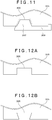
- Fig. 11 is a top plan view of the collection box 90 with its lid closed, showing a relation of a partition plate 305, a recess 306 and protrusions 307, 308 to be described hereinlater.
- the collection box 90 includes a main body 300 and a lid 301.
- the lid 301 has a door-like configuration such that the lid pivotally opens/closes in a direction of the arrow X about a support 302 as a pivot shaft disposed in parallel to a bill stacking direction.
- the lid opens and closes an opening of a storage space constituting the collection box 90.
- the storage space in the collection box 90 is divided by the partition plate 305 into an upper storage portion 303 and a lower storage portion 304.
- the partition plate 305 includes the recess 306 which is widened toward the above-described opening or toward the lid 301.
- a depth length L1 of the collection box 90 is slightly longer than a size L2 of the largest bill handled, while the recess 306 has such a length L2 as to overlap with the bill.
- a collector normally holds a central part of the bills. Therefore, the partition plate 305 shown in Fig. 10 is formed with the recess 306 at the central part of the partition plate 305.
- the recess need not necessarily be formed at the central part of the partition plate so long as the recess corresponds to a bill extraction position.
- the lid 301 is provided with the protrusion 307 which is tapered toward the above-described opening or in a direction away from the lid 301.
- the protrusion 307 is perpendicular to a surface of the lid 301 and is progressively decreased in width in the depth direction of the collection box 90 as seen when the lid 301 is closed.
- the protrusion 307 is configured to be slightly larger than the recess 306 so that there is no clearance between the protrusion and the recess when the lid 301 is closed.
- the protrusion 307 is continuous with the protrusion 308.
- the protrusion 308 protrudes from the lid 301 in the same direction as the protrusion 307.
- the protrusion 308 is formed on the opening side of the lid and between the protrusion 307 and the support 302 of the lid in continuous relation with the protrusion 307.
- the protrusion 308 is moved to a predetermined position as guided by an inclined guide portion 309 formed at the partition plate 305 on the lid-301 side thereof (In the figure, the protrusions 307, 308 are moved into positions under the guide portion 309 and the recess 306).
- the guide portion 309 formed at the partition plate 305 is inclined toward the upper storage portion 303 relative to a partition plane so that a lid-301 side end of the guide portion 309 has a greater height from a bottom of the collection box 90 than that of the protrusion 308. Therefore, when the lid 301 starts to be closed, the protrusion 308 is progressively moved from the support 302 side toward an underside of the guide portion 309 so that the protrusion 307 is moved into position under the recess 306 when the lid 301 is fully closed. In other words, the protrusion 308 guides the lid 301 pivotally closing about the support 302 by being moved into position under the guide portion 309 or on the opposite thereof from an inclination surface thereof.
- the recess 306 of the partition plate 305 is closed with the protrusion 307 of the lid 301. Therefore, even if a bill 400 is rejected as folded or crumpled and stored, the bill 400 will not accidentally enter the lower storage box 304 because there is no clearance to allow an end of the bill to enter the lower storage box.
- the bills can be extracted by opening the lid 301, followed by inserting fingers in the recess 306 for picking up the bills. Hence, the bill extraction handleability is not impaired by the partition plate 305 interfering with the bill extraction operation.
- the partition plate partitioning the storage space is formed with the recess while the lid is provided with the protrusion.
- the embodiment is adapted to guide the protrusion into the predetermined position when the open lid is closed. This ensures that the lid is reliably closed even when a rough handling displaces the protrusion relative to the partition plate.
- the embodiment can achieve an improvement in breakage resistance.
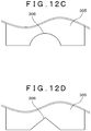
- the recess 306 formed in the partition plate 305 may have a rectangular shape, circular shape, inverted trapezoidal shape or the like.
- the recess of the partition plate is closed with the protrusion of the lid. Even if a bill is rejected as folded or crumpled, the bill will not accidentally enter the lower storage box because there is no clearance to allow an end of the rejected bill to enter the lower storage box.
- a paper sheet storage box having high reliability.
- the recess is configured to widen toward the lid side and to be always overlapped with the bill.
- the box is adapted for easy insertion of a hand to extract the bills.
- the embodiment can provide the paper sheet storage box featuring excellent handleability.
- the embodiment can provide the paper sheet storage box having high reliability. Further, the paper sheet storage box can be reduced in size by forming the storage box in substantially the same size as that of the bill.
- the paper sheet storage box according to the invention is applied to the collection box.
- the invention may also be applied to other storage boxes such as the temporary storage box 40, the return-bill temporary storage box 50, the storage boxes 71 to 75 and the like which have the same functions as this collection box, so as to implement the above-described processes including the received bill counting process, the received bill storage process, the dispensed bill dealing process, the left bill collection process and the like.
Landscapes
- Physics & Mathematics (AREA)
- General Physics & Mathematics (AREA)
- Business, Economics & Management (AREA)
- Accounting & Taxation (AREA)
- Finance (AREA)
- Engineering & Computer Science (AREA)
- Mechanical Engineering (AREA)
- Pile Receivers (AREA)
Applications Claiming Priority (2)
| Application Number | Priority Date | Filing Date | Title |
|---|---|---|---|
| JP2015113355 | 2015-06-03 | ||
| PCT/JP2016/058969 WO2016194442A1 (fr) | 2015-06-03 | 2016-03-22 | Unité de stockage de feuilles de papier et guichet automatique bancaire |
Publications (2)
| Publication Number | Publication Date |
|---|---|
| EP3306579A1 true EP3306579A1 (fr) | 2018-04-11 |
| EP3306579A4 EP3306579A4 (fr) | 2019-02-27 |
Family
ID=57440454
Family Applications (1)
| Application Number | Title | Priority Date | Filing Date |
|---|---|---|---|
| EP16802881.9A Pending EP3306579A4 (fr) | 2015-06-03 | 2016-03-22 | Unité de stockage de feuilles de papier et guichet automatique bancaire |
Country Status (5)
| Country | Link |
|---|---|
| US (1) | US10093510B2 (fr) |
| EP (1) | EP3306579A4 (fr) |
| JP (1) | JP6307664B2 (fr) |
| CN (1) | CN107111910B (fr) |
| WO (1) | WO2016194442A1 (fr) |
Families Citing this family (4)
| Publication number | Priority date | Publication date | Assignee | Title |
|---|---|---|---|---|
| EP3376482B1 (fr) * | 2017-03-17 | 2022-06-22 | Wincor Nixdorf International GmbH | Dispositif de traitement de documents de valeur et procédé de fonctionnement d'un dispositif de traitement de documents de valeur |
| CN108694771B (zh) * | 2017-04-11 | 2019-10-11 | 山东新北洋信息技术股份有限公司 | 纸币处理装置及纸币处理方法 |
| CN108198328A (zh) * | 2018-02-07 | 2018-06-22 | 深圳怡化电脑股份有限公司 | 自助设备的介质存储装置及自助设备的介质传输方法 |
| JP7132737B2 (ja) * | 2018-04-04 | 2022-09-07 | 日立チャネルソリューションズ株式会社 | 紙幣取扱装置 |
Family Cites Families (17)
| Publication number | Priority date | Publication date | Assignee | Title |
|---|---|---|---|---|
| JP2854756B2 (ja) * | 1992-05-29 | 1999-02-03 | 株式会社東芝 | 貨幣処理装置 |
| DE9216283U1 (de) * | 1992-12-01 | 1993-01-14 | Kodak Verwaltung AG, 70327 Stuttgart | Vorrichtung zum Öffnen und Schließen einer Kassette |
| US5732878A (en) * | 1996-06-05 | 1998-03-31 | Lefebure Manufacturing Corporation | Secure currency deposit system having multiply accessible cash cassette |
| CN2573633Y (zh) * | 2002-09-13 | 2003-09-17 | 林建伟 | 一种分隔式多功能钞箱 |
| US7992775B2 (en) * | 2006-11-10 | 2011-08-09 | Diebold Self-Service Systems Division Of Diebold, Incorporated | Automated banking machine apparatus controlled responsive to data bearing records |
| JP5046623B2 (ja) * | 2006-11-24 | 2012-10-10 | マミヤ・オーピー株式会社 | 紙幣識別装置並びにこの紙幣識別装置を収納した遊技媒体貸機 |
| WO2009107165A1 (fr) * | 2008-02-27 | 2009-09-03 | グローリー株式会社 | Appareil de manipulation de billets de banque |
| JP5334531B2 (ja) * | 2008-10-31 | 2013-11-06 | 三洋電機株式会社 | パック電池 |
| US8689962B2 (en) * | 2009-03-25 | 2014-04-08 | Glory Ltd. | Money handling apparatus |
| JP5434538B2 (ja) * | 2009-12-03 | 2014-03-05 | 沖電気工業株式会社 | 媒体処理装置 |
| JP5500196B2 (ja) * | 2012-03-27 | 2014-05-21 | 沖電気工業株式会社 | 紙幣処理装置 |
| JP2013239075A (ja) * | 2012-05-16 | 2013-11-28 | Oki Electric Ind Co Ltd | 媒体集積装置及び媒体処理装置 |
| JP5594400B2 (ja) * | 2013-06-13 | 2014-09-24 | 沖電気工業株式会社 | 自動取引装置 |
| CN203966235U (zh) * | 2014-05-04 | 2014-11-26 | 昆山古鳌电子机械有限公司 | 一种集积纸张类的纸张类集积装置 |
| US9424705B1 (en) * | 2014-07-14 | 2016-08-23 | Glory Ltd. | Money handling apparatus |
| US9430893B1 (en) * | 2014-08-06 | 2016-08-30 | Cummins-Allison Corp. | Systems, methods and devices for managing rejected coins during coin processing |
| CN104240383B (zh) * | 2014-09-24 | 2017-01-25 | 广州广电运通金融电子股份有限公司 | 一种纸币回收箱以及纸币处理装置 |
-
2016
- 2016-03-22 US US15/543,779 patent/US10093510B2/en active Active
- 2016-03-22 EP EP16802881.9A patent/EP3306579A4/fr active Pending
- 2016-03-22 WO PCT/JP2016/058969 patent/WO2016194442A1/fr active Application Filing
- 2016-03-22 JP JP2017521720A patent/JP6307664B2/ja active Active
- 2016-03-22 CN CN201680005017.3A patent/CN107111910B/zh active Active
Also Published As
| Publication number | Publication date |
|---|---|
| CN107111910A (zh) | 2017-08-29 |
| US20180082509A1 (en) | 2018-03-22 |
| JPWO2016194442A1 (ja) | 2017-08-31 |
| CN107111910B (zh) | 2019-07-09 |
| JP6307664B2 (ja) | 2018-04-04 |
| WO2016194442A1 (fr) | 2016-12-08 |
| US10093510B2 (en) | 2018-10-09 |
| EP3306579A4 (fr) | 2019-02-27 |
Similar Documents
| Publication | Publication Date | Title |
|---|---|---|
| KR101056808B1 (ko) | 지폐 취급 장치 | |
| EP3264377B1 (fr) | Dispositif d'automatisation bancaire pour employé de banque et son procédé de commande | |
| JP5089138B2 (ja) | 紙幣取扱装置 | |
| CN101894413B (zh) | 自动交易装置 | |
| JP5834865B2 (ja) | 紙幣入出金機及び紙幣処理装置 | |
| US10093510B2 (en) | Paper sheet storage box and automatic teller machine | |
| JP4772547B2 (ja) | 卓上型硬貨入出金機 | |
| KR940003024B1 (ko) | 자동인출장치 | |
| KR20130027711A (ko) | 지폐처리장치 및 지폐처리방법 | |
| JP6119824B2 (ja) | 紙幣入出金機及び紙幣処理装置 | |
| JP5277757B2 (ja) | 紙幣処理装置 | |
| EP2395483A1 (fr) | Machine de dépôt/retrait de pièces | |
| CN102906794B (zh) | 纸币处理装置 | |
| JP2016184347A (ja) | 紙葉類搬送機構および紙葉類処理装置 | |
| KR100338228B1 (ko) | 자동거래장치 | |
| WO2010097928A1 (fr) | Dispositif de traitement de monnaie | |
| JPH05324982A (ja) | 紙幣処理装置 | |
| JP5501485B2 (ja) | 紙幣取扱装置 | |
| WO2018025308A1 (fr) | Dispositif de manipulation de billets de banque | |
| KR20130078476A (ko) | 지폐처리장치 및 지폐처리방법 | |
| JP6399918B2 (ja) | 貨幣処理機および貨幣処理方法 | |
| JPH03148792A (ja) | 紙幣取扱装置 | |
| KR20190031066A (ko) | 매체의 경로 전환 구조 및 이를 구비한 금융기기 | |
| JPS62219099A (ja) | 紙幣入出金機 | |
| JPH01253080A (ja) | 紙幣取引口機構 |
Legal Events
| Date | Code | Title | Description |
|---|---|---|---|
| STAA | Information on the status of an ep patent application or granted ep patent |
Free format text: STATUS: THE INTERNATIONAL PUBLICATION HAS BEEN MADE |
|
| PUAI | Public reference made under article 153(3) epc to a published international application that has entered the european phase |
Free format text: ORIGINAL CODE: 0009012 |
|
| STAA | Information on the status of an ep patent application or granted ep patent |
Free format text: STATUS: REQUEST FOR EXAMINATION WAS MADE |
|
| 17P | Request for examination filed |
Effective date: 20180103 |
|
| AK | Designated contracting states |
Kind code of ref document: A1 Designated state(s): AL AT BE BG CH CY CZ DE DK EE ES FI FR GB GR HR HU IE IS IT LI LT LU LV MC MK MT NL NO PL PT RO RS SE SI SK SM TR |
|
| AX | Request for extension of the european patent |
Extension state: BA ME |
|
| DAV | Request for validation of the european patent (deleted) | ||
| DAX | Request for extension of the european patent (deleted) | ||
| A4 | Supplementary search report drawn up and despatched |
Effective date: 20190128 |
|
| RIC1 | Information provided on ipc code assigned before grant |
Ipc: G07D 11/50 20190101ALI20190122BHEP Ipc: G07F 19/00 20060101ALI20190122BHEP Ipc: G07D 11/12 20190101ALI20190122BHEP Ipc: B65H 31/24 20060101AFI20190122BHEP |
|
| STAA | Information on the status of an ep patent application or granted ep patent |
Free format text: STATUS: EXAMINATION IS IN PROGRESS |
|
| STAA | Information on the status of an ep patent application or granted ep patent |
Free format text: STATUS: EXAMINATION IS IN PROGRESS |
|
| 17Q | First examination report despatched |
Effective date: 20211206 |