EP3305418A1 - Vorrichtung zum erwärmen polymerer pulver mittels strahlung bei pulverbeschichtungsverfahren - Google Patents
Vorrichtung zum erwärmen polymerer pulver mittels strahlung bei pulverbeschichtungsverfahren Download PDFInfo
- Publication number
- EP3305418A1 EP3305418A1 EP17189424.9A EP17189424A EP3305418A1 EP 3305418 A1 EP3305418 A1 EP 3305418A1 EP 17189424 A EP17189424 A EP 17189424A EP 3305418 A1 EP3305418 A1 EP 3305418A1
- Authority
- EP
- European Patent Office
- Prior art keywords
- wavelength range
- radiation
- powder
- diaphragm
- microns
- Prior art date
- Legal status (The legal status is an assumption and is not a legal conclusion. Google has not performed a legal analysis and makes no representation as to the accuracy of the status listed.)
- Granted
Links
Images
Classifications
-
- B—PERFORMING OPERATIONS; TRANSPORTING
- B05—SPRAYING OR ATOMISING IN GENERAL; APPLYING FLUENT MATERIALS TO SURFACES, IN GENERAL
- B05C—APPARATUS FOR APPLYING FLUENT MATERIALS TO SURFACES, IN GENERAL
- B05C19/00—Apparatus specially adapted for applying particulate materials to surfaces
- B05C19/04—Apparatus specially adapted for applying particulate materials to surfaces the particulate material being projected, poured or allowed to flow onto the surface of the work
-
- H—ELECTRICITY
- H05—ELECTRIC TECHNIQUES NOT OTHERWISE PROVIDED FOR
- H05B—ELECTRIC HEATING; ELECTRIC LIGHT SOURCES NOT OTHERWISE PROVIDED FOR; CIRCUIT ARRANGEMENTS FOR ELECTRIC LIGHT SOURCES, IN GENERAL
- H05B3/00—Ohmic-resistance heating
- H05B3/0033—Heating devices using lamps
- H05B3/0038—Heating devices using lamps for industrial applications
- H05B3/0057—Heating devices using lamps for industrial applications for plastic handling and treatment
-
- B—PERFORMING OPERATIONS; TRANSPORTING
- B05—SPRAYING OR ATOMISING IN GENERAL; APPLYING FLUENT MATERIALS TO SURFACES, IN GENERAL
- B05C—APPARATUS FOR APPLYING FLUENT MATERIALS TO SURFACES, IN GENERAL
- B05C19/00—Apparatus specially adapted for applying particulate materials to surfaces
- B05C19/06—Storage, supply or control of the application of particulate material; Recovery of excess particulate material
-
- B—PERFORMING OPERATIONS; TRANSPORTING
- B05—SPRAYING OR ATOMISING IN GENERAL; APPLYING FLUENT MATERIALS TO SURFACES, IN GENERAL
- B05D—PROCESSES FOR APPLYING FLUENT MATERIALS TO SURFACES, IN GENERAL
- B05D1/00—Processes for applying liquids or other fluent materials
- B05D1/02—Processes for applying liquids or other fluent materials performed by spraying
- B05D1/04—Processes for applying liquids or other fluent materials performed by spraying involving the use of an electrostatic field
- B05D1/06—Applying particulate materials
-
- B—PERFORMING OPERATIONS; TRANSPORTING
- B05—SPRAYING OR ATOMISING IN GENERAL; APPLYING FLUENT MATERIALS TO SURFACES, IN GENERAL
- B05D—PROCESSES FOR APPLYING FLUENT MATERIALS TO SURFACES, IN GENERAL
- B05D3/00—Pretreatment of surfaces to which liquids or other fluent materials are to be applied; After-treatment of applied coatings, e.g. intermediate treating of an applied coating preparatory to subsequent applications of liquids or other fluent materials
- B05D3/02—Pretreatment of surfaces to which liquids or other fluent materials are to be applied; After-treatment of applied coatings, e.g. intermediate treating of an applied coating preparatory to subsequent applications of liquids or other fluent materials by baking
- B05D3/0254—After-treatment
- B05D3/0263—After-treatment with IR heaters
-
- C—CHEMISTRY; METALLURGY
- C09—DYES; PAINTS; POLISHES; NATURAL RESINS; ADHESIVES; COMPOSITIONS NOT OTHERWISE PROVIDED FOR; APPLICATIONS OF MATERIALS NOT OTHERWISE PROVIDED FOR
- C09D—COATING COMPOSITIONS, e.g. PAINTS, VARNISHES OR LACQUERS; FILLING PASTES; CHEMICAL PAINT OR INK REMOVERS; INKS; CORRECTING FLUIDS; WOODSTAINS; PASTES OR SOLIDS FOR COLOURING OR PRINTING; USE OF MATERIALS THEREFOR
- C09D177/00—Coating compositions based on polyamides obtained by reactions forming a carboxylic amide link in the main chain; Coating compositions based on derivatives of such polymers
- C09D177/02—Polyamides derived from omega-amino carboxylic acids or from lactams thereof
-
- C—CHEMISTRY; METALLURGY
- C09—DYES; PAINTS; POLISHES; NATURAL RESINS; ADHESIVES; COMPOSITIONS NOT OTHERWISE PROVIDED FOR; APPLICATIONS OF MATERIALS NOT OTHERWISE PROVIDED FOR
- C09D—COATING COMPOSITIONS, e.g. PAINTS, VARNISHES OR LACQUERS; FILLING PASTES; CHEMICAL PAINT OR INK REMOVERS; INKS; CORRECTING FLUIDS; WOODSTAINS; PASTES OR SOLIDS FOR COLOURING OR PRINTING; USE OF MATERIALS THEREFOR
- C09D5/00—Coating compositions, e.g. paints, varnishes or lacquers, characterised by their physical nature or the effects produced; Filling pastes
- C09D5/03—Powdery paints
-
- H—ELECTRICITY
- H05—ELECTRIC TECHNIQUES NOT OTHERWISE PROVIDED FOR
- H05B—ELECTRIC HEATING; ELECTRIC LIGHT SOURCES NOT OTHERWISE PROVIDED FOR; CIRCUIT ARRANGEMENTS FOR ELECTRIC LIGHT SOURCES, IN GENERAL
- H05B3/00—Ohmic-resistance heating
- H05B3/0033—Heating devices using lamps
- H05B3/009—Heating devices using lamps heating devices not specially adapted for a particular application
-
- B—PERFORMING OPERATIONS; TRANSPORTING
- B05—SPRAYING OR ATOMISING IN GENERAL; APPLYING FLUENT MATERIALS TO SURFACES, IN GENERAL
- B05D—PROCESSES FOR APPLYING FLUENT MATERIALS TO SURFACES, IN GENERAL
- B05D2202/00—Metallic substrate
- B05D2202/10—Metallic substrate based on Fe
-
- B—PERFORMING OPERATIONS; TRANSPORTING
- B05—SPRAYING OR ATOMISING IN GENERAL; APPLYING FLUENT MATERIALS TO SURFACES, IN GENERAL
- B05D—PROCESSES FOR APPLYING FLUENT MATERIALS TO SURFACES, IN GENERAL
- B05D2401/00—Form of the coating product, e.g. solution, water dispersion, powders or the like
- B05D2401/30—Form of the coating product, e.g. solution, water dispersion, powders or the like the coating being applied in other forms than involving eliminable solvent, diluent or dispersant
- B05D2401/32—Form of the coating product, e.g. solution, water dispersion, powders or the like the coating being applied in other forms than involving eliminable solvent, diluent or dispersant applied as powders
-
- B—PERFORMING OPERATIONS; TRANSPORTING
- B05—SPRAYING OR ATOMISING IN GENERAL; APPLYING FLUENT MATERIALS TO SURFACES, IN GENERAL
- B05D—PROCESSES FOR APPLYING FLUENT MATERIALS TO SURFACES, IN GENERAL
- B05D2505/00—Polyamides
-
- B—PERFORMING OPERATIONS; TRANSPORTING
- B29—WORKING OF PLASTICS; WORKING OF SUBSTANCES IN A PLASTIC STATE IN GENERAL
- B29C—SHAPING OR JOINING OF PLASTICS; SHAPING OF MATERIAL IN A PLASTIC STATE, NOT OTHERWISE PROVIDED FOR; AFTER-TREATMENT OF THE SHAPED PRODUCTS, e.g. REPAIRING
- B29C35/00—Heating, cooling or curing, e.g. crosslinking or vulcanising; Apparatus therefor
- B29C35/02—Heating or curing, e.g. crosslinking or vulcanizing during moulding, e.g. in a mould
- B29C35/08—Heating or curing, e.g. crosslinking or vulcanizing during moulding, e.g. in a mould by wave energy or particle radiation
- B29C35/0805—Heating or curing, e.g. crosslinking or vulcanizing during moulding, e.g. in a mould by wave energy or particle radiation using electromagnetic radiation
- B29C2035/0822—Heating or curing, e.g. crosslinking or vulcanizing during moulding, e.g. in a mould by wave energy or particle radiation using electromagnetic radiation using IR radiation
Definitions
- the present invention relates to an apparatus for heating polymeric powders by radiation in powder coating processes, a process for heating the powders, and the use of the apparatus.
- the powder particles used for powder coating generally consist of dry, granular particles having a diameter between 1 and 140 microns. Chemically, these are usually based on epoxy or polyester resins. In addition, hybrid systems are widely used which contain both epoxy and polyester resins as binders. Powder particles based on thermoplastic polymers are also frequently used.
- the powder particles are applied electrostatically.
- electrostatic powder coating an electrically charged powder cloud is first generated.
- the particles of the same name are transported to the workpiece surface. There they beat down, adhere electrostatically and form the powder coating layer.
- the melting and / or crosslinking of the powder particles is usually carried out by heating in an oven by convection.
- the heating by convection sometimes takes a longer time, so that the charge of the particles decreases and the adhesion decreases. In this case, the particles may simply fall off before melting or crosslinking occurs.
- the quality of the coating decreases significantly in this case.
- the heating of the powder particles can also be effected by means of electromagnetic radiation.
- a radiation source is advantageous which emits a large part of its radiation in the wavelength range (2.5-10 ⁇ m).
- Radiant heaters such as ceramic heaters meet this requirement, but are very slow in terms of temperature control. It is therefore required for many applications, a radiator, which has its maximum radiation in the wavelength range of 2.5 to 10 microns and can be controlled quickly with respect to the radiation intensity.
- the object has been to provide a device which is suitable for the heating of polymeric powder particles, but does not have the disadvantages of the prior art.
- the device should have a maximum radiation in the wavelength range of 2.5 - 10 microns and allow a rapid change in the radiation intensity and thus a rapid change in temperature.
- a device of the type mentioned which comprises a radiation source, a housing and a diaphragm.
- the radiation source of the device has its maximum radiation power in the wavelength range of 0.78-2.5 ⁇ m.
- the term "in the wavelength range” or “in the entire wavelength range” is to be understood to mean that the radiation source has a maximum radiant power at at least one wavelength of the specified wavelength range for the radiation source.
- the aperture has an absorption coefficient of at least 0.8 in the wavelength range of 0.78 to 2.5 ⁇ m.
- the term “in the wavelength range” or “in the entire wavelength range” is to be understood for the diaphragm in such a way that the diaphragm has at least the specified degree of absorption at all wavelengths of the specified wavelength range.
- the aperture is preferably aligned perpendicular to the radiation source in the housing. With respect to the polymer powder particles to be heated, the diaphragm is preferably aligned in parallel.
- a device can be provided as jet heating which can generate a radiation necessary for the efficient heating of polymeric powder particles and at the same time can be regulated quickly with regard to intensity or temperature.
- the particles are not heated directly by the radiation source but by the diaphragm.
- the diaphragm absorbs the radiation energy of the radiation source and emits the energy in a shifted wavelength range.
- the radiation maximum of the device according to the invention is therefore preferably at a wavelength of more than 2.5 microns and less than 4.8 microns, preferably between 3.1 microns and 4.2 microns.
- the aperture has an absorptivity of at least 0.8, preferably at least 0.9 and particularly preferably at least 0.95 in the entire wavelength range of 0.78-2.5 ⁇ m.
- the thickness of the diaphragm is preferably at most 1 mm. Preferably, the thickness is at most 0.5 mm, more preferably at most 0.3 mm and most preferably at most 0.1 mm.
- the aperture should preferably have a low heat capacity. As a result, the aperture reacts relatively quickly to changes in the radiation intensity of the radiation source. As a result, a rapid change in temperature of the device is possible.
- suitable materials of the panel are selected from oxidized metals such as steel sheets, aluminum, copper or silver sheets, graphite, silicon, surface-treated and / or colored ceramics, mineral fibers and colored glasses, with anodized and colored, especially black-colored, aluminum being preferred , Combinations of the materials mentioned are also possible.
- the radiation source is surrounded by a housing whose surfaces facing the radiation source preferably have a low absorption coefficient of less than 0.4 in the wavelength range of 0.78-2.5 ⁇ m, more preferably less than 0.3.
- the housing has at least one opening in the direction of the diaphragm.
- suitable materials of the housing are metals, preferably with a polished surface (Rz according to DIN EN ISO 4287 of a maximum of 2 ⁇ m), metallized ceramics and ceramics with a low degree of absorption (less than 0.4 in the wavelength range from 0.78 to 2.5 ⁇ m).
- the term "in the wavelength range” or "in the entire wavelength range” is to be understood for the housing in such a way that the housing has a lower than the stated absorption coefficient at all wavelengths of the specified wavelength range
- the device according to the invention additionally comprises a protective pane.
- the diaphragm is arranged between the radiation source and the protective pane.
- the protective screen prevents direct contact of the heated panel with the polymeric powder particles.
- the protective screen can be transparent.
- the transmission of the protective pane is preferably at least 0.9 in the wavelength range of 2.5-4.8 ⁇ m.
- the protective glass can be selected, for example, from chalcogenide glass or sapphire glass. The term "in the wavelength range” or "in the entire wavelength range” is to be understood for the protective glass in that the protective glass has at least the specified transmittance at all wavelengths of the specified wavelength range
- Housing and aperture are preferably thermally decoupled. If a protective pane is included, it is preferred that the housing, cover and protective pane are thermally decoupled from one another.
- the degree of absorption and the transmission are determined by means of a Cary 5000 UV-Vis-NIR spectrophotometer from Varian according to DIN EN ISO 13468-2: 2006-07. The measurement takes place under standard conditions (23 ° C / 50%).
- suitable polymers which can be processed by means of the device according to the invention are polyamides such as polyamide 6, polyamide 11 or polyamide 12, copolyamides such as polyamide 46, polyamide 66, polyamide 613, polyamide 106, polyamide 1010, polyamide 1012, polyamide 1212, Polyamide 1013, polyamide 12/1012, polyolefins such as polyethylene and polypropylene, polyesters and polyaryletherketones (PEAK) such as polyetheretherketone.
- polyamides such as polyamide 6, polyamide 11 or polyamide 12
- copolyamides such as polyamide 46, polyamide 66, polyamide 613, polyamide 106
- polyamide 1010 polyamide 1012, polyamide 1212, Polyamide 1013, polyamide 12/1012
- polyolefins such as polyethylene and polypropylene
- PET polyaryletherketones
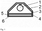
- the device comprises a radiation source (1) whose maximum radiation power is in the wavelength range of 0.78 - 2.5 ⁇ m.
- the radiation source is surrounded by a housing (2), the inner surface (surface, which faces the radiation source) has a low absorption coefficient.
- On one side of the housing (2) is an opening in which a diaphragm (4) sits, which has a high degree of absorption.
- Aperture (4) and housing (2) are preferably thermally decoupled by an insulator (3).
- the device according to the invention preferably has a transparent protective pane (6) in order to avoid direct contact of the panel with powder particles.
- Disc (6) and diaphragm (4) are preferably thermally decoupled by an insulator (5).
- the heating of the powder particles can be carried out until melting.
- the present invention is a method for heating polymeric powder particles, wherein the device according to the invention is used.
- polymer powders are exposed to the radiation of the device.
- the powder particles are preferably heated at a heating rate of at least 2 K / s, preferably at least 10 K / s, and more preferably at least 20 K / s heated.
- the temperature change is measured with a pyrometer (optris CTfastLT) from Optris.
- Another object is the use of the device according to the invention for heating polymer powder particles, preferably in powder coating processes.
- the devices described in the examples are used to heat powders.
- an undyed polyamide 12 powder with the key figures listed in Table 1 is used.
- the experiments are carried out under standard conditions (23 ° C / 50%).
- the radiation sources have a power consumption of 500 W.
- a 0.5 mm thick flat powder layer is applied to a polished steel plate.
- the jet heaters are positioned at a distance of 20 mm above the surface of the powder.
- the powder, the metal plate and the radiant heaters are conditioned for 2 hours in the standard atmosphere before the measurement is started.
- the jet heaters in the examples are turned on and the time taken for the powder to melt is measured.
- a halogen radiator comprising a halogen lamp as the radiation source, a housing and a protective screen, has its maximum radiation power in the wavelength range of 0.78-2.5 ⁇ m.
- Example 2 ceramic radiator (not according to the invention)
- a ceramic radiator has its maximum radiant power in the IR-C wavelength range (3 - 1000 ⁇ m).
- the halogen radiator from Example 1 has an aperture made of oxidized steel sheet with a thickness of 0.5 mm and with an absorption factor of more than 0.88 in the wavelength range of 0.78-2.5 ⁇ m.
- the halogen emitter of Example 1 has a shutter made of anodized and black-colored aluminum sheet with a thickness of 0.3 mm and an absorbance of about 0.95 in the wavelength range of 0.78 - 2.5 microns.
- Table 1 Powder characteristic values of the polyamide 12 used value unit Type of test / tester / test parameters bulk density 0,450 g / cm 3 DIN EN ISO 60 Grain size d50 57 microns Malvern Mastersizer 2000, dry measurement, 20-40g powder added by Scirocco dry dispersing unit. Feeding rate of vibrating chute 70%, dispersing air pressure 3 bar. The measurement time of the sample is 5 seconds (5000 individual measurements), refractive index and blue light value set at 1.52.
- the inventive devices of Examples 3 and 4 take much less time to melt the powder.
- applications such as electrostatic coating, minicoating or in the powder-based processes mentioned in ISO / ASTM 52900, a significant acceleration of the process and thus of the productivity can be achieved.
- a smaller amount of energy is needed to melt the powder.
- the device according to the invention makes it possible to heat or melt thicker layers of powder or several layers.
Landscapes
- Chemical & Material Sciences (AREA)
- Life Sciences & Earth Sciences (AREA)
- Engineering & Computer Science (AREA)
- Materials Engineering (AREA)
- Wood Science & Technology (AREA)
- Organic Chemistry (AREA)
- Chemical Kinetics & Catalysis (AREA)
- Application Of Or Painting With Fluid Materials (AREA)
- Paints Or Removers (AREA)
- Resistance Heating (AREA)
- Processing And Handling Of Plastics And Other Materials For Molding In General (AREA)
- Processes Of Treating Macromolecular Substances (AREA)
Abstract
Description
- Die vorliegende Erfindung betrifft eine Vorrichtung zum Erwärmen polymerer Pulver durch Strahlung bei Pulverbeschichtungsverfahren, ein Verfahren zum Erwärmen der Pulver sowie die Verwendung der Vorrichtung.
- Die zur Pulverbeschichtung verwendeten Pulverpartikel bestehen im Allgemeinen aus trockenen, körnigen Partikeln, die einen Durchmesser zwischen 1 und 140 µm haben. Chemisch basieren diese meist auf Epoxid- oder Polyesterharzen. Daneben sind Hybridsysteme verbreitet, die sowohl Epoxid- als auch Polyesterharze als Bindemittel enthalten. Pulverpartikel auf Basis von thermoplastischen Polymeren werden ebenfalls häufig verwendet.
- Stand der Technik ist, dass die Pulverpartikel elektrostatisch appliziert werden. Bei der elektrostatischen Pulverbeschichtung wird zunächst eine elektrisch geladene Pulverwolke erzeugt. Die gleichnamig geladenen Partikel werden zur Werkstückoberfläche transportiert. Dort schlagen sie sich nieder, haften dort elektrostatisch und bilden die Pulverlackschicht. Möglich ist eine Aufladung durch Corona-Aufladung/lonisation oder durch Reibung. Das Aufschmelzen und/oder Vernetzen der Pulverpartikel erfolgt üblicherweise durch das Aufheizen in einem Ofen durch Konvektion. Das Aufheizen durch Konvektion dauert mitunter eine längere Zeit, so dass die Aufladung der Partikel nachlässt und die Haftung abnimmt. In diesem Fall können die Partikel einfach abfallen, bevor es zu einem Aufschmelzen oder Vernetzen kommt. Die Qualität der Beschichtung nimmt in diesem Fall deutlich ab. Das Erwärmen der Pulverpartikel kann auch mittels elektromagnetischer Strahlung erfolgen. Dies hat den Vorteil, dass das Aufschmelzen/Vernetzen deutlich schneller erfolgen kann. Ein Problem ist jedoch, dass viele ungefärbte Polymere elektromagnetische Strahlung im sichtbaren und Nahinfrarot (IR-A) Wellenlängenbereich (0,78 - 1,4µm) nur sehr schlecht absorbieren bzw. die Absorption stark von der Einfärbung der Polymerpartikel abhängt. Im Fall der ungefärbten Polymerpartikel wird wegen der schlechten Absorption ein erheblicher Teil der Strahlungsenergie nicht genutzt. Bei eingefärbten Polymeren muss die Strahlungsmenge immer an der jeweiligen Einfärbung des Polymers angepasst werden. Ein weiterer Nachteil des aktuellen Stands der Technik ist der mögliche Kontakt von Pulverpartikel mit heißen Oberflächen und der damit verbundenen erhöhten Gefahr von Staubexplosionen.
- Für das Erwärmen der polymeren Pulverpartikel ist daher eine Strahlungsquelle von Vorteil, die ein Großteil ihrer Strahlung im Wellenlängenbereich (2,5 - 10 µm) abgibt. Strahlheizungen wie Keramikstrahler erfüllen diese Anforderung, sind aber sehr träge bzgl. der Temperaturregelung. Es wird daher für viele Anwendungen ein Strahler benötigt, der sein Strahlungsmaximum im Wellenlängenbereich von 2,5 bis 10 µm hat und sich hinsichtlich der Strahlungsintensität schnell regeln lässt.
- Demgemäß bestand die Aufgabe in der Bereitstellung einer Vorrichtung, die für das Erwärmen polymerer Pulverpartikel geeignet ist, jedoch die Nachteile des Standes der Technik nicht aufweist. Insbesondere sollte die Vorrichtung ein Strahlungsmaximum im Wellenlängenbereich von 2,5 - 10 µm aufweisen und eine zügige Änderung der Strahlungsintensität und damit eine schnelle Temperaturänderung ermöglichen.
- Demgemäß wurde eine Vorrichtung der eingangs genannten Art gefunden, die eine Strahlungsquelle, ein Gehäuse und eine Blende umfasst. Die Strahlungsquelle der Vorrichtung hat im Wellenlängenbereich von 0,78 - 2,5 µm ihre maximale Strahlungsleistung. Der Begriff "im Wellenlängenbereich" oder "im gesamten Wellenlängenbereich" ist für die Strahlungsquelle dahingehend zu verstehen, dass die Strahlungsquelle bei zumindest einer Wellenlänge des angegebenen Wellenlängenbereichs eine maximale Strahlungsleistung aufweist. Die Blende hat im Wellenlängenbereich von 0,78 - 2,5 µm einen Absorptionsgrad von mindestens 0,8. Der Begriff "im Wellenlängenbereich" oder "im gesamten Wellenlängenbereich" ist für die Blende dahingehend zu verstehen, dass die Blende bei allen Wellenlängen des angegebenen Wellenlängenbereichs mindestens den angegebenen Absorptionsgrad aufweist. Die Blende wird vorzugsweise senkrecht zur Strahlungsquelle in dem Gehäuse ausgerichtet. Bezüglich der zu erwärmenden Polymerpulverpartikel ist die Blende vorzugsweise parallel ausgerichtet.
- Überraschend wurde gefunden, dass mit der erfindungsgemäßen Vorrichtung eine Vorrichtung als Strahlheizung bereit gestellt werden kann, die eine für das effiziente Erwärmen von polymeren Pulverpartikeln notwendige Strahlung erzeugen und zugleich hinsichtlich Intensität bzw. Temperatur schnell geregelt werden kann. Die Partikel werden nicht direkt durch die Strahlungsquelle, sondern von der Blende erwärmt. Die Blende nimmt die Strahlungsenergie der Strahlungsquelle auf und gibt die Energie in einem verschobenen Wellenlängenbereich ab. Das Strahlungsmaximum der erfindungsgemäßen Vorrichtung liegt demzufolge vorzugsweise bei einer Wellenlänge von mehr als 2,5 µm und unter 4,8 µm, bevorzugt zwischen 3,1 µm und 4,2 µm.
- Geeignete Strahlungsquellen sind IR-A Strahlungsquellen (Wellenlängen von 0,78 bis 1,4 µm) wie Halogenlampen oder NIR-Laser (NIR = nahes Infrarot).
- Die Blende hat im gesamten Wellenlängenbereich von 0,78 - 2,5 µm einen Absorptionsgrad von mindestens 0,8, bevorzugt mindestens 0,9 und besonders bevorzugt mindestens 0,95. Die Dicke der Blende beträgt vorzugsweise maximal 1 mm. Bevorzugt beträgt die Dicke maximal 0,5 mm, besonders bevorzugt maximal 0,3 mm und ganz besonders bevorzugt maximal 0,1 mm.
- Die Blende sollte vorzugsweise eine geringe Wärmekapazität aufweisen. Hierdurch reagiert die Blende relativ schnell auf Änderungen der Strahlungsintensität der Strahlungsquelle. Dadurch ist eine zügige Temperaturänderung der Vorrichtung möglich.
- Beispiele für geeignete Materialien der Blende sind ausgewählt aus oxidierten Metallen wie Stahlblechen, Aluminium-, Kupfer- oder Silberblechen, Graphit, Silicium, oberflächenbehandelten und/oder gefärbten Keramiken, Mineralfasern und eingefärbten Gläsern, wobei eloxiertes und gefärbtes, insbesondere schwarz eingefärbtes, Aluminium bevorzugt ist. Kombinationen aus den genannten Materialien sind auch möglich.
- Die Strahlungsquelle wird von einem Gehäuse umgeben, dessen der Strahlungsquelle zugewandten Oberflächen bevorzugt einen niedrigen Absorptionsgrad von weniger als 0,4 im Wellenlängenbereich von 0,78 - 2,5 µm haben, besonders bevorzugt weniger als 0,3. Das Gehäuse weist zumindest eine Öffnung in Richtung der Blende auf. Beispiele für geeignete Materialien des Gehäuses sind Metalle, bevorzugt mit polierter Oberfläche (Rz nach DIN EN ISO 4287 von max. 2µm), metallisierte Keramiken sowie Keramiken mit niedrigem Absorptionsgrad (kleiner 0,4 im Wellenlängenbereich von 0,78 - 2,5 µm). Der Begriff "im Wellenlängenbereich" oder "im gesamten Wellenlängenbereich" ist für das Gehäuse dahingehend zu verstehen, dass das Gehäuse bei allen Wellenlängen des angegebenen Wellenlängenbereichs einen geringeren als den angegebenen Absorptionsgrad aufweist
- In einer bevorzugten Ausführungsform umfasst die erfindungsgemäße Vorrichtung zusätzlich eine Schutzscheibe. Hierbei ist die Blende zwischen der Strahlungsquelle und der Schutzscheibe angeordnet. Die Schutzscheibe verhindert einen direkten Kontakt von der erhitzten Blende mit den polymeren Pulverpartikeln. Die Schutzscheibe kann transparent sein. Die Transmission der Schutzscheibe beträgt im Wellenlängenbereich von 2,5 - 4,8 µm vorzugsweise mindestens 0,9. Die Schutzscheibe kann beispielsweise ausgewählt werden aus Chalkogenidglas oder Saphirglas. Der Begriff "im Wellenlängenbereich" oder "im gesamten Wellenlängenbereich" ist für die Schutzscheibe dahingehend zu verstehen, dass die Schutzscheibe bei allen Wellenlängen des angegebenen Wellenlängenbereichs mindestens den angegebenen Transmissionsgrad aufweist
- Mit der Kombination von mehreren erfindungsgemäßen Vorrichtungen ist es möglich, auch größere Flächen zu erwärmen. Werden diese Vorrichtungen unterschiedlich geregelt, ist es möglich, die Temperaturverteilung auf der zu erwärmenden Fläche den technischen Erfordernissen anzupassen. In einer weiteren alternativen Ausführung werden mehrere Strahlquellen mit einer Blende kombiniert, um größere Flächen zu erwärmen.
- Gehäuse und Blende sind vorzugsweise thermisch entkoppelt. Sofern eine Schutzscheibe umfasst ist, ist es bevorzugt, dass Gehäuse, Blende und Schutzscheibe voneinander thermisch entkoppelt sind.
- Der Absorptionssgrad und die Transmission werden mittels eines Cary 5000 UV-Vis-NIR Spectrophotometer der Firma Varian nach DIN EN ISO 13468-2:2006-07 ermittelt. Die Messung findet unter Normbedingungen (23°C/50%) statt.
- Beispiele geeigneter Polymere, die mittels der erfindungsgemäßen Vorrichtung verarbeitet werden können, sind Polyamide wie Polyamid 6, Polyamid 11 oder Polyamid 12, Co-Polyamide wie Polyamid 46, Polyamid 66, Polyamid 613, Polyamid 106, Polyamid 1010, Polyamid 1012, Polyamid 1212, Polyamid 1013, Polyamid 12/1012, Polyolefine wie Polyethylen und Polypropylen, Polyester und Polyaryletherketone (PEAK) wie Polyetheretherketon.
- In
Fig. 1 ist die erfindungsgemäße Vorrichtung exemplarisch dargestellt. Die Vorrichtung umfasst eine Strahlungsquelle (1), deren maximale Strahlungsleistung im Wellenlängenbereich von 0,78 - 2,5 µm liegt. Die Strahlungsquelle wird von einem Gehäuse (2) umgeben, dessen Innenoberfläche (Oberfläche, die der Strahlungsquelle zugewandt ist) einen niedrigen Absorptionsgrad hat. An einer Seite des Gehäuses (2) ist eine Öffnung, in der eine Blende (4) sitzt, die einen hohen Absorptionsgrad besitzt. Bevorzugt sind Blende (4) und Gehäuse (2) durch einen Isolator (3) thermisch entkoppelt. Bevorzugt weist die erfindungsgemäße Vorrichtung eine transparente Schutzscheibe (6) auf, um einen direkten Kontakt von Blende mit Pulverpartikeln zu vermeiden. Scheibe (6) und Blende (4) sind bevorzugt durch einen Isolator (5) thermisch entkoppelt. - Das Erwärmen der Pulverpartikel kann bis zum Aufschmelzen durchgeführt werden.
- Ebenfalls Gegenstand der vorliegenden Erfindung ist ein Verfahren zum Erwärmen von polymeren Pulverpartikeln, wobei die erfindungsgemäße Vorrichtung eingesetzt wird. Hierbei werden Polymerpulver der Strahlung der Vorrichtung ausgesetzt. Die Pulverpartikel werden vorzugsweise mit einer Aufheizrate von mindestens 2 K/s erwärmt, bevorzugt mindestens 10 K/s, und besonders bevorzugt mindestens 20 K/s erwärmt. Die Temperaturänderung wird mit einem Pyrometer (optris CTfastLT) der Firma Optris gemessen.
- Ein weiterer Gegenstand ist die Verwendung der erfindungsgemäßen Vorrichtung zum Erwärmen von Polymerpulverpartikeln, vorzugsweise in Pulverbeschichtungsverfahren.
- Die in den Beispielen beschriebenen Vorrichtungen werden genutzt, um Pulver zu erwärmen. Für die Versuche wird ein ungefärbtes Polyamid 12-Pulver mit den in der Tabelle 1 aufgeführten Kennzahlen genutzt. Die Versuche werden bei Normklima (23 °C / 50 %) durchgeführt. Die Strahlungsquellen haben eine Leistungsaufnahme von 500 W. In allen Beispielen wird auf eine Platte aus poliertem Stahl eine 0,5 mm dicke ebene Pulverschicht aufgetragen. Die Strahlheizungen werden in einem Abstand von 20 mm über der Pulveroberfläche positioniert. Das Pulver, die Metallplatte und die Strahlheizungen werden 2 h in dem Normklima konditioniert, bevor die Messung gestartet wird. Die Strahlheizungen in den Beispielen werden eingeschaltet und die Zeit gemessen, die benötigt wird, bis das Pulver anfängt zu schmelzen.
- Ein Halogenstrahler, umfassend eine Halogenlampe als Strahlungsquelle, ein Gehäuse und eine Schutzscheibe, hat seine maximale Strahlungsleistung im Wellenlängenbereich von 0,78 - 2,5 µm.
- Ein Keramikstrahler hat seine maximale Strahlungsleistung im IR-C Wellenlängenbereich (3 - 1000 µm).
- Der Halogenstrahler aus Beispiel 1 verfügt über eine Blende aus oxidiertem Stahlblech mit einer Dicke von 0,5mm und mit einem Absorptionsgrad von über 0,88 im Wellenlängenbereich von 0,78 - 2,5 µm.
- Der Halogenstrahler aus Beispiel 1 verfügt über eine Blende aus eloxiertem und schwarz eingefärbtem Aluminiumblech mit einer Dicke von 0,3 mm und einem Absorptionsgrad von über 0,95 im Wellenlängenbereich von 0,78 - 2,5 µm.
Tabelle 1: Pulverkennwerte des eingesetzten Polyamid 12 Wert Einheit Prüfart/Prüfgerät/Prüfparameter Schüttdichte 0,450 g/cm3 DIN EN ISO 60 Korngröße d50 57 µm Malvern Mastersizer 2000, Trockenmessung, 20-40g Pulver mittels Scirocco Trockendispergiergerät zudosiert. Zuführrate Rüttelrinne 70%, Dispergierluftdruck 3 bar. Die Messzeit der Probe 5 Sekunden (5000 Einzelmessungen), Brechungsindex und Blaulichtwert mit 1,52 festgelegt. Auswertung über Mie-Theorie Korngröße d10 36 µm Malvern Mastersizer 2000, Parameter siehe Korngröße d50 Korngröße d90 82 µm Malvern Mastersizer 2000, Parameter siehe Korngröße d50 <10,48µm 1,4 % Malvern Mastersizer 2000, Parameter siehe Korngröße d50 Fließfähigkeit 28 s DIN EN ISO 6186, Verfahren A, Durchmesser Düsenauslauf 15mm Lösungsviskosität 1,58 - ISO 307, Schott AVS Pro, Lösemittel m-Kresol sauer, Volumetrisches Verfahren, Doppelbestimmung, Lösetemperatur 100°C, Lösezeit 2h, Polymerkonzentration 5g/l Messtemperatur 25°C BET (spez. Oberfläche) 6,7 m2/g ISO 9277, Micromeritics TriStar 3000, Gasadsorption von Stickstoff, diskontinuierlichen volumetrischen Verfahren, 7 Messpunkte bei Relativdrücken P/P0 zwischen ca. 0,05 und ca. 0,20, Kalibrierung des Totvolumens mittels He(99,996 %), Probenvorbereitung 1 h bei 23°C + 16 h bei 80°C unter Vakuum, spez. Oberfläche auf die entgaste Probe bezogen, Auswertung erfolgte mittels Mehrpunktbestimmung Schmelzpunkt 1. Aufheizung 187 °C DIN 53765 DSC 7 v. Perkin Elmer Heiz-/Kühlrate 20K/min Rekristallisationstemperatur 142 °C DIN 53765 DSC 7 v. Perkin Elmer Heiz-/Kühlrate 20K/min Materialkonditionierung Material wird vor Verarbeitung/Analyse 24h bei 23°C und 50% Luftfeuchtigkeit gelagert Tabelle 2: Versuchsergebnisse Beispiel 1 Beispiel 2 Beispiel 3 Beispiel 4 Benötigte Zeit, bis Pulver anfängt zu schmelzen in s 491 151 84 73 - Die erfindungsgemäßen Vorrichtungen aus den Beispielen 3 und 4 benötigen eine deutlich geringere Zeit, um das Pulver zu schmelzen. In Anwendungen wie zum Beispiel dem elektrostatischen Beschichten, dem Minicoating oder in den in der ISO/ASTM 52900 genannten Pulver basierenden Verfahren kann eine deutliche Beschleunigung des Prozesses und somit der Produktivität erzielt werden. Zudem wird auch eine geringere Energiemenge benötigt, um das Pulver aufzuschmelzen. Die erfindungsgemäße Vorrichtung ermöglicht so dickere Pulverschichten oder mehrere Schichten zu erwärmen bzw. aufzuschmelzen.
Claims (11)
- Vorrichtung zum Erwärmen von Polymerpulverpartikel, umfassend eine Strahlungsquelle(1), ein Gehäuse (2) und eine Blende (4), dadurch gekennzeichnet, dass die Strahlungsquelle (1) im Wellenlängenbereich von 0,78 - 2,5 µm ihre maximale Strahlungsleistung und die Blende (4) im Wellenlängenbereich von 0,78 - 2,5 µm einen Absorptionsgrad von mindestens 0,8 hat.
- Vorrichtung gemäß Anspruch 1, dadurch gekennzeichnet, dass die der Strahlungsquelle zugewandten Oberflächen des Gehäuses (2) im Wellenlängenbereich von 0,78 - 2,5 µm einen Absorptionsgrad von weniger als 0,4 hat.
- Vorrichtung gemäß einem der vorherigen Ansprüche, dadurch gekennzeichnet, dass die Blende (4) zwischen der Strahlungsquelle (1) und einer Schutzscheibe (6) angeordnet ist.
- Vorrichtung gemäß Anspruch 3, dadurch gekennzeichnet, das die Schutzscheibe (6) im Wellenlängenbereich von 2,5 µm - 10 µm eine Transmission von mindestens 0,9 hat.
- Vorrichtung gemäß einem der Ansprüche 3 oder 4, dadurch gekennzeichnet, dass Gehäuse (2), Blende (4) und Schutzscheibe (6) thermisch entkoppelt sind.
- Vorrichtung gemäß einem der vorherigen Ansprüche, dadurch gekennzeichnet, dass die Blende (4) aus eloxiertem und gefärbtem Aluminium besteht.
- Vorrichtung gemäß einem der vorherigen Ansprüche, dadurch gekennzeichnet, dass die Blende (4) eine Dicke von maximal 1 mm hat.
- Verfahren zum Erwärmen von Polymerpulverpartikeln mittels einer Vorrichtung gemäß einer der Ansprüche 1 bis 7, dadurch gekennzeichnet, dass die Polymerpulverpartikel der Strahlung der Vorrichtung ausgesetzt wird.
- Verfahren gemäß Anspruch 8, dadurch gekennzeichnet, dass die Polymerpulverpartikel einer Aufheizrate von mindestens 2 K/s erwärmt werden.
- Verwendung einer Vorrichtung der Ansprüche 1 bis 7 zum Erwärmen von Polymerpulverpartikeln.
- Verwendung nach Anspruch 10 in Pulverbeschichtungsverfahren.
Applications Claiming Priority (2)
| Application Number | Priority Date | Filing Date | Title |
|---|---|---|---|
| DE102016219182 | 2016-10-04 | ||
| DE102017203523.4A DE102017203523A1 (de) | 2016-10-04 | 2017-03-03 | Vorrichtung zum Erwärmen polymerer Pulver mittels Strahlung bei Pulverbeschichtungsverfahren |
Publications (2)
| Publication Number | Publication Date |
|---|---|
| EP3305418A1 true EP3305418A1 (de) | 2018-04-11 |
| EP3305418B1 EP3305418B1 (de) | 2022-11-02 |
Family
ID=59010816
Family Applications (1)
| Application Number | Title | Priority Date | Filing Date |
|---|---|---|---|
| EP17189424.9A Active EP3305418B1 (de) | 2016-10-04 | 2017-09-05 | Vorrichtung zum erwärmen polymerer pulver mittels strahlung bei pulverbeschichtungsverfahren |
Country Status (7)
| Country | Link |
|---|---|
| US (1) | US10356849B2 (de) |
| EP (1) | EP3305418B1 (de) |
| JP (1) | JP6538794B2 (de) |
| CN (1) | CN107890974B (de) |
| DE (1) | DE102017203523A1 (de) |
| ES (1) | ES2934740T3 (de) |
| PL (1) | PL3305418T3 (de) |
Families Citing this family (4)
| Publication number | Priority date | Publication date | Assignee | Title |
|---|---|---|---|---|
| EP3501695A1 (de) | 2017-12-22 | 2019-06-26 | Evonik Degussa GmbH | Vorrichtung zur schichtweisen herstellung von dreidimensionalen objekten sowie herstellungsverfahren dazu |
| GB2580040B (en) * | 2018-12-19 | 2022-01-19 | Stratasys Powder Production Ltd | Heater arrangements and apparatus for layer-by-layer formation of three-dimensional objects |
| EP3698956A1 (de) | 2019-02-21 | 2020-08-26 | Evonik Operations GmbH | Verfahren zur oberflächenbearbeitung von polymeren dreidimensionalen objekten |
| CN113064146B (zh) * | 2021-04-23 | 2023-10-03 | 沈阳工程学院 | 一种用于风电功率预测声雷达的防护装置及控制方法 |
Citations (5)
| Publication number | Priority date | Publication date | Assignee | Title |
|---|---|---|---|---|
| JPH08285694A (ja) * | 1995-04-18 | 1996-11-01 | Nikon Corp | 赤外線撮像装置 |
| US6531086B1 (en) * | 1997-04-30 | 2003-03-11 | Speed Part Rp Ab | Method and device for manufacturing three-dimensional bodies |
| DE10352184A1 (de) * | 2003-11-05 | 2005-06-23 | Arccure Technologies Gmbh | Vorrichtung zum Härten und/oder Trocknen einer Beschichtung auf einem Substrat |
| EP2226180A1 (de) * | 2009-03-05 | 2010-09-08 | Krones AG | Vorrichtung sowie Verfahren zum Erwärmen von Kunststoffvorformlingen mit teiltransparentem Strahler |
| EP3222410A1 (de) * | 2016-03-24 | 2017-09-27 | Evonik Degussa GmbH | Verfahren zum aufschmelzen/sintern von pulverpartikeln zur schichtweisen herstellung von dreidimensionalen objekten |
Family Cites Families (10)
| Publication number | Priority date | Publication date | Assignee | Title |
|---|---|---|---|---|
| JPS6067543A (ja) * | 1983-09-21 | 1985-04-17 | Sumitomo Chem Co Ltd | 発泡成形用粒状ポリオレフィン材料 |
| JPS62112627A (ja) * | 1985-11-11 | 1987-05-23 | Dainippon Ink & Chem Inc | ビニルエステル・エチレン系共重合体 |
| JP2978716B2 (ja) * | 1994-04-22 | 1999-11-15 | ウシオ電機株式会社 | 遠赤外線ヒータ |
| GB9822822D0 (en) * | 1998-10-19 | 1998-12-16 | Dyno Particles As | Particles |
| JP2002143748A (ja) * | 2000-11-08 | 2002-05-21 | Inoac Corp | 塗装システム |
| JP4263529B2 (ja) | 2003-05-14 | 2009-05-13 | 日本電熱株式会社 | 加熱装置 |
| KR101285143B1 (ko) * | 2008-03-31 | 2013-07-12 | 테크노 폴리머 가부시키가이샤 | 열가소성 수지 성형품의 제조방법 및 열가소성 수지 입자 조성물 |
| JP5797413B2 (ja) | 2011-01-25 | 2015-10-21 | 光洋サーモシステム株式会社 | ヒータユニットおよび熱処理装置 |
| JP5694983B2 (ja) * | 2012-03-27 | 2015-04-01 | 日本碍子株式会社 | 赤外線ヒーター |
| CN104811247A (zh) * | 2014-01-23 | 2015-07-29 | 温成 | 非可见光发射装置 |
-
2017
- 2017-03-03 DE DE102017203523.4A patent/DE102017203523A1/de not_active Withdrawn
- 2017-09-05 PL PL17189424.9T patent/PL3305418T3/pl unknown
- 2017-09-05 EP EP17189424.9A patent/EP3305418B1/de active Active
- 2017-09-05 ES ES17189424T patent/ES2934740T3/es active Active
- 2017-09-14 US US15/705,052 patent/US10356849B2/en active Active
- 2017-09-29 CN CN201710907262.XA patent/CN107890974B/zh active Active
- 2017-10-04 JP JP2017194280A patent/JP6538794B2/ja active Active
Patent Citations (5)
| Publication number | Priority date | Publication date | Assignee | Title |
|---|---|---|---|---|
| JPH08285694A (ja) * | 1995-04-18 | 1996-11-01 | Nikon Corp | 赤外線撮像装置 |
| US6531086B1 (en) * | 1997-04-30 | 2003-03-11 | Speed Part Rp Ab | Method and device for manufacturing three-dimensional bodies |
| DE10352184A1 (de) * | 2003-11-05 | 2005-06-23 | Arccure Technologies Gmbh | Vorrichtung zum Härten und/oder Trocknen einer Beschichtung auf einem Substrat |
| EP2226180A1 (de) * | 2009-03-05 | 2010-09-08 | Krones AG | Vorrichtung sowie Verfahren zum Erwärmen von Kunststoffvorformlingen mit teiltransparentem Strahler |
| EP3222410A1 (de) * | 2016-03-24 | 2017-09-27 | Evonik Degussa GmbH | Verfahren zum aufschmelzen/sintern von pulverpartikeln zur schichtweisen herstellung von dreidimensionalen objekten |
Also Published As
| Publication number | Publication date |
|---|---|
| CN107890974B (zh) | 2022-07-19 |
| US20180098384A1 (en) | 2018-04-05 |
| CN107890974A (zh) | 2018-04-10 |
| JP6538794B2 (ja) | 2019-07-03 |
| ES2934740T3 (es) | 2023-02-24 |
| PL3305418T3 (pl) | 2023-04-11 |
| US10356849B2 (en) | 2019-07-16 |
| JP2018060793A (ja) | 2018-04-12 |
| EP3305418B1 (de) | 2022-11-02 |
| DE102017203523A1 (de) | 2017-06-29 |
Similar Documents
| Publication | Publication Date | Title |
|---|---|---|
| EP3305418B1 (de) | Vorrichtung zum erwärmen polymerer pulver mittels strahlung bei pulverbeschichtungsverfahren | |
| DE102007016656B4 (de) | PAEK-Pulver, insbesondere zur Verwendung in einem Verfahren zum schichtweisen Herstellen eines dreidimensionalen Objektes, sowie Verfahren zu dessen Herstellung | |
| US10934207B2 (en) | Methods for producing an assembly of hexaboride fine particles | |
| EP1765578B1 (de) | Vorrichtung und verfahren zum schichtweisen herstellen eines dreidimensionalen objekts | |
| EP3655234A1 (de) | Verfahren und vorrichtung zum herstellen von 3d-formteilen mit spektrumswandler | |
| DE102010004036A1 (de) | Vorrichtung zum generativen Herstellen eines dreidimensionalen Objekts mit kontinuierlicher Wärmezufuhr | |
| EP3222410B1 (de) | Verfahren und vorrichtung zum aufschmelzen/sintern von pulverpartikeln zur schichtweisen herstellung von dreidimensionalen objekten | |
| DE102004037318A1 (de) | Radiowellen-Absorber und Verfahren zu seiner Herstellung | |
| WO2011101494A1 (de) | Verfahren zum beschichten von bauteilen | |
| DE102011079518A1 (de) | Verbesserte Bauteileigenschaften durch optimierte Prozessführung im Laser-Sintern | |
| WO2013186041A1 (de) | Partikelhaltige klebefolie zum temporären schutz einer werkstückoberfläche, insbesondere bei laserbearbeitung, und verbund mit einer derartigen folie | |
| DE1940090B2 (de) | Verfahren und vorrichtung zum ueberziehen der innenwandung von hohlbehaeltern verschiedener form mit einem ueberzug aus plastischen massen | |
| EP2857438B1 (de) | Druckausgleichselement und Herstellungsverfahren dafür | |
| DE102013107514A1 (de) | Verfahren zur Herstellung eines Verbundhalbzeugs | |
| DE112016000089B4 (de) | Harzformungsform | |
| DE102010001971A1 (de) | Verfahren zur Herstellung von Glitter | |
| DE69014626T2 (de) | Antibeschlagfilm und Verfahren zu seiner Herstellung. | |
| DE102023208853A1 (de) | Verfahren und Vorrichtung zur additiven Fertigung eines Bauteils | |
| DE69312488T2 (de) | Verfahren zur herstellung eines materials mit elektrostatischer aufladungsminderung | |
| DE102017108403A1 (de) | Vorrichtung zum Applizieren einer mehrschichtigen Folie auf Basis eines thermoplastischen Polymermaterials mit einer Haftvermittlerschicht auf eine Oberfläche eines Stahlbands und Verfahren zum Beschichten eines Stahlbands | |
| DE1646538A1 (de) | Baukomponenten und Verfahren zu ihrer Herstellung | |
| DE102014208249A1 (de) | Verfahren zur Herstellung von Polymerfolien oder plattenförmigen Elementen aus Polymer | |
| AT526559B1 (de) | Scheinwerferbauelement, prüfverfahren sowie herstellungs- und prüfverfahren | |
| DE4228115C2 (de) | Verfahren zum Verschweißen und Trennschweißen von Polyolefinfolien | |
| US11022533B2 (en) | Method of controlling particles size of fillers in extrudable compositions, compositions comprising the fillers and devices made from the compositions |
Legal Events
| Date | Code | Title | Description |
|---|---|---|---|
| PUAI | Public reference made under article 153(3) epc to a published international application that has entered the european phase |
Free format text: ORIGINAL CODE: 0009012 |
|
| STAA | Information on the status of an ep patent application or granted ep patent |
Free format text: STATUS: REQUEST FOR EXAMINATION WAS MADE |
|
| 17P | Request for examination filed |
Effective date: 20170905 |
|
| AK | Designated contracting states |
Kind code of ref document: A1 Designated state(s): AL AT BE BG CH CY CZ DE DK EE ES FI FR GB GR HR HU IE IS IT LI LT LU LV MC MK MT NL NO PL PT RO RS SE SI SK SM TR |
|
| AX | Request for extension of the european patent |
Extension state: BA ME |
|
| RAP1 | Party data changed (applicant data changed or rights of an application transferred) |
Owner name: EVONIK OPERATIONS GMBH |
|
| STAA | Information on the status of an ep patent application or granted ep patent |
Free format text: STATUS: EXAMINATION IS IN PROGRESS |
|
| 17Q | First examination report despatched |
Effective date: 20200114 |
|
| GRAP | Despatch of communication of intention to grant a patent |
Free format text: ORIGINAL CODE: EPIDOSNIGR1 |
|
| STAA | Information on the status of an ep patent application or granted ep patent |
Free format text: STATUS: GRANT OF PATENT IS INTENDED |
|
| INTG | Intention to grant announced |
Effective date: 20220714 |
|
| RIC1 | Information provided on ipc code assigned before grant |
Ipc: B29C 35/08 20060101ALN20220705BHEP Ipc: C09D 177/02 20060101ALI20220705BHEP Ipc: H05B 3/00 20060101ALI20220705BHEP Ipc: B05D 1/06 20060101ALI20220705BHEP Ipc: B05D 3/02 20060101AFI20220705BHEP |
|
| GRAS | Grant fee paid |
Free format text: ORIGINAL CODE: EPIDOSNIGR3 |
|
| GRAA | (expected) grant |
Free format text: ORIGINAL CODE: 0009210 |
|
| STAA | Information on the status of an ep patent application or granted ep patent |
Free format text: STATUS: THE PATENT HAS BEEN GRANTED |
|
| AK | Designated contracting states |
Kind code of ref document: B1 Designated state(s): AL AT BE BG CH CY CZ DE DK EE ES FI FR GB GR HR HU IE IS IT LI LT LU LV MC MK MT NL NO PL PT RO RS SE SI SK SM TR |
|
| REG | Reference to a national code |
Ref country code: GB Ref legal event code: FG4D Free format text: NOT ENGLISH |
|
| REG | Reference to a national code |
Ref country code: CH Ref legal event code: EP Ref country code: AT Ref legal event code: REF Ref document number: 1528370 Country of ref document: AT Kind code of ref document: T Effective date: 20221115 |
|
| REG | Reference to a national code |
Ref country code: DE Ref legal event code: R096 Ref document number: 502017014027 Country of ref document: DE |
|
| REG | Reference to a national code |
Ref country code: IE Ref legal event code: FG4D Free format text: LANGUAGE OF EP DOCUMENT: GERMAN |
|
| REG | Reference to a national code |
Ref country code: ES Ref legal event code: FG2A Ref document number: 2934740 Country of ref document: ES Kind code of ref document: T3 Effective date: 20230224 |
|
| REG | Reference to a national code |
Ref country code: LT Ref legal event code: MG9D |
|
| REG | Reference to a national code |
Ref country code: NL Ref legal event code: MP Effective date: 20221102 |
|
| PG25 | Lapsed in a contracting state [announced via postgrant information from national office to epo] |
Ref country code: SE Free format text: LAPSE BECAUSE OF FAILURE TO SUBMIT A TRANSLATION OF THE DESCRIPTION OR TO PAY THE FEE WITHIN THE PRESCRIBED TIME-LIMIT Effective date: 20221102 Ref country code: PT Free format text: LAPSE BECAUSE OF FAILURE TO SUBMIT A TRANSLATION OF THE DESCRIPTION OR TO PAY THE FEE WITHIN THE PRESCRIBED TIME-LIMIT Effective date: 20230302 Ref country code: NO Free format text: LAPSE BECAUSE OF FAILURE TO SUBMIT A TRANSLATION OF THE DESCRIPTION OR TO PAY THE FEE WITHIN THE PRESCRIBED TIME-LIMIT Effective date: 20230202 Ref country code: LT Free format text: LAPSE BECAUSE OF FAILURE TO SUBMIT A TRANSLATION OF THE DESCRIPTION OR TO PAY THE FEE WITHIN THE PRESCRIBED TIME-LIMIT Effective date: 20221102 Ref country code: FI Free format text: LAPSE BECAUSE OF FAILURE TO SUBMIT A TRANSLATION OF THE DESCRIPTION OR TO PAY THE FEE WITHIN THE PRESCRIBED TIME-LIMIT Effective date: 20221102 |
|
| PG25 | Lapsed in a contracting state [announced via postgrant information from national office to epo] |
Ref country code: RS Free format text: LAPSE BECAUSE OF FAILURE TO SUBMIT A TRANSLATION OF THE DESCRIPTION OR TO PAY THE FEE WITHIN THE PRESCRIBED TIME-LIMIT Effective date: 20221102 Ref country code: LV Free format text: LAPSE BECAUSE OF FAILURE TO SUBMIT A TRANSLATION OF THE DESCRIPTION OR TO PAY THE FEE WITHIN THE PRESCRIBED TIME-LIMIT Effective date: 20221102 Ref country code: IS Free format text: LAPSE BECAUSE OF FAILURE TO SUBMIT A TRANSLATION OF THE DESCRIPTION OR TO PAY THE FEE WITHIN THE PRESCRIBED TIME-LIMIT Effective date: 20230302 Ref country code: HR Free format text: LAPSE BECAUSE OF FAILURE TO SUBMIT A TRANSLATION OF THE DESCRIPTION OR TO PAY THE FEE WITHIN THE PRESCRIBED TIME-LIMIT Effective date: 20221102 Ref country code: GR Free format text: LAPSE BECAUSE OF FAILURE TO SUBMIT A TRANSLATION OF THE DESCRIPTION OR TO PAY THE FEE WITHIN THE PRESCRIBED TIME-LIMIT Effective date: 20230203 |
|
| P01 | Opt-out of the competence of the unified patent court (upc) registered |
Effective date: 20230524 |
|
| PG25 | Lapsed in a contracting state [announced via postgrant information from national office to epo] |
Ref country code: NL Free format text: LAPSE BECAUSE OF FAILURE TO SUBMIT A TRANSLATION OF THE DESCRIPTION OR TO PAY THE FEE WITHIN THE PRESCRIBED TIME-LIMIT Effective date: 20221102 |
|
| PG25 | Lapsed in a contracting state [announced via postgrant information from national office to epo] |
Ref country code: SM Free format text: LAPSE BECAUSE OF FAILURE TO SUBMIT A TRANSLATION OF THE DESCRIPTION OR TO PAY THE FEE WITHIN THE PRESCRIBED TIME-LIMIT Effective date: 20221102 Ref country code: RO Free format text: LAPSE BECAUSE OF FAILURE TO SUBMIT A TRANSLATION OF THE DESCRIPTION OR TO PAY THE FEE WITHIN THE PRESCRIBED TIME-LIMIT Effective date: 20221102 Ref country code: EE Free format text: LAPSE BECAUSE OF FAILURE TO SUBMIT A TRANSLATION OF THE DESCRIPTION OR TO PAY THE FEE WITHIN THE PRESCRIBED TIME-LIMIT Effective date: 20221102 Ref country code: DK Free format text: LAPSE BECAUSE OF FAILURE TO SUBMIT A TRANSLATION OF THE DESCRIPTION OR TO PAY THE FEE WITHIN THE PRESCRIBED TIME-LIMIT Effective date: 20221102 |
|
| REG | Reference to a national code |
Ref country code: DE Ref legal event code: R097 Ref document number: 502017014027 Country of ref document: DE |
|
| PG25 | Lapsed in a contracting state [announced via postgrant information from national office to epo] |
Ref country code: SK Free format text: LAPSE BECAUSE OF FAILURE TO SUBMIT A TRANSLATION OF THE DESCRIPTION OR TO PAY THE FEE WITHIN THE PRESCRIBED TIME-LIMIT Effective date: 20221102 Ref country code: AL Free format text: LAPSE BECAUSE OF FAILURE TO SUBMIT A TRANSLATION OF THE DESCRIPTION OR TO PAY THE FEE WITHIN THE PRESCRIBED TIME-LIMIT Effective date: 20221102 |
|
| PLBE | No opposition filed within time limit |
Free format text: ORIGINAL CODE: 0009261 |
|
| STAA | Information on the status of an ep patent application or granted ep patent |
Free format text: STATUS: NO OPPOSITION FILED WITHIN TIME LIMIT |
|
| 26N | No opposition filed |
Effective date: 20230803 |
|
| PG25 | Lapsed in a contracting state [announced via postgrant information from national office to epo] |
Ref country code: SI Free format text: LAPSE BECAUSE OF FAILURE TO SUBMIT A TRANSLATION OF THE DESCRIPTION OR TO PAY THE FEE WITHIN THE PRESCRIBED TIME-LIMIT Effective date: 20221102 |
|
| PG25 | Lapsed in a contracting state [announced via postgrant information from national office to epo] |
Ref country code: LU Free format text: LAPSE BECAUSE OF NON-PAYMENT OF DUE FEES Effective date: 20230905 |
|
| PG25 | Lapsed in a contracting state [announced via postgrant information from national office to epo] |
Ref country code: LU Free format text: LAPSE BECAUSE OF NON-PAYMENT OF DUE FEES Effective date: 20230905 Ref country code: MC Free format text: LAPSE BECAUSE OF FAILURE TO SUBMIT A TRANSLATION OF THE DESCRIPTION OR TO PAY THE FEE WITHIN THE PRESCRIBED TIME-LIMIT Effective date: 20221102 |
|
| REG | Reference to a national code |
Ref country code: IE Ref legal event code: MM4A |
|
| PG25 | Lapsed in a contracting state [announced via postgrant information from national office to epo] |
Ref country code: IE Free format text: LAPSE BECAUSE OF NON-PAYMENT OF DUE FEES Effective date: 20230905 |
|
| PG25 | Lapsed in a contracting state [announced via postgrant information from national office to epo] |
Ref country code: IE Free format text: LAPSE BECAUSE OF NON-PAYMENT OF DUE FEES Effective date: 20230905 |
|
| PGFP | Annual fee paid to national office [announced via postgrant information from national office to epo] |
Ref country code: CZ Payment date: 20240826 Year of fee payment: 8 |
|
| PG25 | Lapsed in a contracting state [announced via postgrant information from national office to epo] |
Ref country code: BG Free format text: LAPSE BECAUSE OF FAILURE TO SUBMIT A TRANSLATION OF THE DESCRIPTION OR TO PAY THE FEE WITHIN THE PRESCRIBED TIME-LIMIT Effective date: 20221102 |
|
| REG | Reference to a national code |
Ref country code: AT Ref legal event code: MM01 Ref document number: 1528370 Country of ref document: AT Kind code of ref document: T Effective date: 20230905 |
|
| PG25 | Lapsed in a contracting state [announced via postgrant information from national office to epo] |
Ref country code: BG Free format text: LAPSE BECAUSE OF FAILURE TO SUBMIT A TRANSLATION OF THE DESCRIPTION OR TO PAY THE FEE WITHIN THE PRESCRIBED TIME-LIMIT Effective date: 20221102 |
|
| PG25 | Lapsed in a contracting state [announced via postgrant information from national office to epo] |
Ref country code: AT Free format text: LAPSE BECAUSE OF NON-PAYMENT OF DUE FEES Effective date: 20230905 |
|
| PG25 | Lapsed in a contracting state [announced via postgrant information from national office to epo] |
Ref country code: AT Free format text: LAPSE BECAUSE OF NON-PAYMENT OF DUE FEES Effective date: 20230905 |
|
| PG25 | Lapsed in a contracting state [announced via postgrant information from national office to epo] |
Ref country code: CY Free format text: LAPSE BECAUSE OF FAILURE TO SUBMIT A TRANSLATION OF THE DESCRIPTION OR TO PAY THE FEE WITHIN THE PRESCRIBED TIME-LIMIT; INVALID AB INITIO Effective date: 20170905 |
|
| PG25 | Lapsed in a contracting state [announced via postgrant information from national office to epo] |
Ref country code: HU Free format text: LAPSE BECAUSE OF FAILURE TO SUBMIT A TRANSLATION OF THE DESCRIPTION OR TO PAY THE FEE WITHIN THE PRESCRIBED TIME-LIMIT; INVALID AB INITIO Effective date: 20170905 |
|
| REG | Reference to a national code |
Ref country code: CH Ref legal event code: U11 Free format text: ST27 STATUS EVENT CODE: U-0-0-U10-U11 (AS PROVIDED BY THE NATIONAL OFFICE) Effective date: 20251001 |
|
| PGFP | Annual fee paid to national office [announced via postgrant information from national office to epo] |
Ref country code: DE Payment date: 20250919 Year of fee payment: 9 |
|
| PGFP | Annual fee paid to national office [announced via postgrant information from national office to epo] |
Ref country code: PL Payment date: 20250829 Year of fee payment: 9 Ref country code: IT Payment date: 20250923 Year of fee payment: 9 |
|
| PGFP | Annual fee paid to national office [announced via postgrant information from national office to epo] |
Ref country code: BE Payment date: 20250918 Year of fee payment: 9 Ref country code: GB Payment date: 20250919 Year of fee payment: 9 |
|
| PGFP | Annual fee paid to national office [announced via postgrant information from national office to epo] |
Ref country code: FR Payment date: 20250922 Year of fee payment: 9 |
|
| PG25 | Lapsed in a contracting state [announced via postgrant information from national office to epo] |
Ref country code: TR Free format text: LAPSE BECAUSE OF FAILURE TO SUBMIT A TRANSLATION OF THE DESCRIPTION OR TO PAY THE FEE WITHIN THE PRESCRIBED TIME-LIMIT Effective date: 20221102 |
|
| PGFP | Annual fee paid to national office [announced via postgrant information from national office to epo] |
Ref country code: CH Payment date: 20251001 Year of fee payment: 9 |
|
| PGFP | Annual fee paid to national office [announced via postgrant information from national office to epo] |
Ref country code: ES Payment date: 20251028 Year of fee payment: 9 |
|
| PG25 | Lapsed in a contracting state [announced via postgrant information from national office to epo] |
Ref country code: CZ Free format text: LAPSE BECAUSE OF NON-PAYMENT OF DUE FEES Effective date: 20250905 |