US20180098384A1 - Apparatus for heating polymeric powders by means of radiation in powder coating methods - Google Patents
Apparatus for heating polymeric powders by means of radiation in powder coating methods Download PDFInfo
- Publication number
- US20180098384A1 US20180098384A1 US15/705,052 US201715705052A US2018098384A1 US 20180098384 A1 US20180098384 A1 US 20180098384A1 US 201715705052 A US201715705052 A US 201715705052A US 2018098384 A1 US2018098384 A1 US 2018098384A1
- Authority
- US
- United States
- Prior art keywords
- screen
- wavelength range
- radiation
- radiation source
- heating
- Prior art date
- Legal status (The legal status is an assumption and is not a legal conclusion. Google has not performed a legal analysis and makes no representation as to the accuracy of the status listed.)
- Granted
Links
- 239000000843 powder Substances 0.000 title claims abstract description 54
- 230000005855 radiation Effects 0.000 title claims abstract description 54
- 238000010438 heat treatment Methods 0.000 title claims abstract description 26
- 238000000576 coating method Methods 0.000 title claims description 9
- 239000002245 particle Substances 0.000 claims abstract description 41
- 238000002835 absorbance Methods 0.000 claims abstract description 18
- 229920000642 polymer Polymers 0.000 claims description 21
- 238000000034 method Methods 0.000 claims description 16
- 239000011248 coating agent Substances 0.000 claims description 6
- 239000004411 aluminium Substances 0.000 claims description 4
- 229910052782 aluminium Inorganic materials 0.000 claims description 4
- XAGFODPZIPBFFR-UHFFFAOYSA-N aluminium Chemical compound [Al] XAGFODPZIPBFFR-UHFFFAOYSA-N 0.000 claims description 4
- 238000002834 transmittance Methods 0.000 claims description 4
- 229910052736 halogen Inorganic materials 0.000 description 8
- 150000002367 halogens Chemical class 0.000 description 8
- 239000000919 ceramic Substances 0.000 description 6
- 239000000463 material Substances 0.000 description 5
- JHWNWJKBPDFINM-UHFFFAOYSA-N Laurolactam Chemical compound O=C1CCCCCCCCCCCN1 JHWNWJKBPDFINM-UHFFFAOYSA-N 0.000 description 4
- 229920000299 Nylon 12 Polymers 0.000 description 4
- 230000004927 fusion Effects 0.000 description 4
- 238000005259 measurement Methods 0.000 description 4
- 229910000831 Steel Inorganic materials 0.000 description 3
- 238000004132 cross linking Methods 0.000 description 3
- 229910052751 metal Inorganic materials 0.000 description 3
- 239000002184 metal Substances 0.000 description 3
- 230000001105 regulatory effect Effects 0.000 description 3
- 239000010959 steel Substances 0.000 description 3
- -1 steel sheets Chemical class 0.000 description 3
- 238000012360 testing method Methods 0.000 description 3
- 238000001816 cooling Methods 0.000 description 2
- 230000007423 decrease Effects 0.000 description 2
- 238000004090 dissolution Methods 0.000 description 2
- 230000005670 electromagnetic radiation Effects 0.000 description 2
- 239000003822 epoxy resin Substances 0.000 description 2
- 238000011156 evaluation Methods 0.000 description 2
- 238000002474 experimental method Methods 0.000 description 2
- LNEPOXFFQSENCJ-UHFFFAOYSA-N haloperidol Chemical compound C1CC(O)(C=2C=CC(Cl)=CC=2)CCN1CCCC(=O)C1=CC=C(F)C=C1 LNEPOXFFQSENCJ-UHFFFAOYSA-N 0.000 description 2
- 239000012212 insulator Substances 0.000 description 2
- 239000010410 layer Substances 0.000 description 2
- RLSSMJSEOOYNOY-UHFFFAOYSA-N m-cresol Chemical compound CC1=CC=CC(O)=C1 RLSSMJSEOOYNOY-UHFFFAOYSA-N 0.000 description 2
- 238000002844 melting Methods 0.000 description 2
- 230000008018 melting Effects 0.000 description 2
- 150000002739 metals Chemical class 0.000 description 2
- 229920000647 polyepoxide Polymers 0.000 description 2
- 229920001225 polyester resin Polymers 0.000 description 2
- 239000004645 polyester resin Substances 0.000 description 2
- IJGRMHOSHXDMSA-UHFFFAOYSA-N Atomic nitrogen Chemical compound N#N IJGRMHOSHXDMSA-UHFFFAOYSA-N 0.000 description 1
- OKTJSMMVPCPJKN-UHFFFAOYSA-N Carbon Chemical compound [C] OKTJSMMVPCPJKN-UHFFFAOYSA-N 0.000 description 1
- RYGMFSIKBFXOCR-UHFFFAOYSA-N Copper Chemical compound [Cu] RYGMFSIKBFXOCR-UHFFFAOYSA-N 0.000 description 1
- 229920000571 Nylon 11 Polymers 0.000 description 1
- 229920003189 Nylon 4,6 Polymers 0.000 description 1
- 229920002292 Nylon 6 Polymers 0.000 description 1
- 229920002302 Nylon 6,6 Polymers 0.000 description 1
- 239000004696 Poly ether ether ketone Substances 0.000 description 1
- 239000004952 Polyamide Substances 0.000 description 1
- 239000004698 Polyethylene Substances 0.000 description 1
- 239000004743 Polypropylene Substances 0.000 description 1
- BQCADISMDOOEFD-UHFFFAOYSA-N Silver Chemical compound [Ag] BQCADISMDOOEFD-UHFFFAOYSA-N 0.000 description 1
- 230000001133 acceleration Effects 0.000 description 1
- 239000011230 binding agent Substances 0.000 description 1
- 230000033228 biological regulation Effects 0.000 description 1
- 239000005387 chalcogenide glass Substances 0.000 description 1
- 239000011247 coating layer Substances 0.000 description 1
- 238000004040 coloring Methods 0.000 description 1
- 230000001143 conditioned effect Effects 0.000 description 1
- 230000003750 conditioning effect Effects 0.000 description 1
- 239000010949 copper Substances 0.000 description 1
- 229910052802 copper Inorganic materials 0.000 description 1
- 230000001419 dependent effect Effects 0.000 description 1
- 229910001873 dinitrogen Inorganic materials 0.000 description 1
- 239000006185 dispersion Substances 0.000 description 1
- 238000009826 distribution Methods 0.000 description 1
- 239000000428 dust Substances 0.000 description 1
- 238000009503 electrostatic coating Methods 0.000 description 1
- 238000004880 explosion Methods 0.000 description 1
- 239000011521 glass Substances 0.000 description 1
- 239000010439 graphite Substances 0.000 description 1
- 229910002804 graphite Inorganic materials 0.000 description 1
- 229910052500 inorganic mineral Inorganic materials 0.000 description 1
- 239000011707 mineral Substances 0.000 description 1
- 238000012986 modification Methods 0.000 description 1
- 230000004048 modification Effects 0.000 description 1
- 229920002647 polyamide Polymers 0.000 description 1
- 229920006260 polyaryletherketone Polymers 0.000 description 1
- 229920000728 polyester Polymers 0.000 description 1
- 229920002530 polyetherether ketone Polymers 0.000 description 1
- 229920000573 polyethylene Polymers 0.000 description 1
- 229920000098 polyolefin Polymers 0.000 description 1
- 229920001155 polypropylene Polymers 0.000 description 1
- 238000002360 preparation method Methods 0.000 description 1
- 238000012545 processing Methods 0.000 description 1
- 229910052594 sapphire Inorganic materials 0.000 description 1
- 239000010980 sapphire Substances 0.000 description 1
- 229910052710 silicon Inorganic materials 0.000 description 1
- 239000010703 silicon Substances 0.000 description 1
- 239000004332 silver Substances 0.000 description 1
- 229910052709 silver Inorganic materials 0.000 description 1
- 239000002904 solvent Substances 0.000 description 1
- 238000001179 sorption measurement Methods 0.000 description 1
- 239000005315 stained glass Substances 0.000 description 1
- 239000000126 substance Substances 0.000 description 1
- 229920001169 thermoplastic Polymers 0.000 description 1
- ZSDSQXJSNMTJDA-UHFFFAOYSA-N trifluralin Chemical compound CCCN(CCC)C1=C([N+]([O-])=O)C=C(C(F)(F)F)C=C1[N+]([O-])=O ZSDSQXJSNMTJDA-UHFFFAOYSA-N 0.000 description 1
Images
Classifications
-
- B—PERFORMING OPERATIONS; TRANSPORTING
- B05—SPRAYING OR ATOMISING IN GENERAL; APPLYING FLUENT MATERIALS TO SURFACES, IN GENERAL
- B05C—APPARATUS FOR APPLYING FLUENT MATERIALS TO SURFACES, IN GENERAL
- B05C19/00—Apparatus specially adapted for applying particulate materials to surfaces
- B05C19/04—Apparatus specially adapted for applying particulate materials to surfaces the particulate material being projected, poured or allowed to flow onto the surface of the work
-
- H—ELECTRICITY
- H05—ELECTRIC TECHNIQUES NOT OTHERWISE PROVIDED FOR
- H05B—ELECTRIC HEATING; ELECTRIC LIGHT SOURCES NOT OTHERWISE PROVIDED FOR; CIRCUIT ARRANGEMENTS FOR ELECTRIC LIGHT SOURCES, IN GENERAL
- H05B3/00—Ohmic-resistance heating
- H05B3/0033—Heating devices using lamps
- H05B3/0038—Heating devices using lamps for industrial applications
- H05B3/0057—Heating devices using lamps for industrial applications for plastic handling and treatment
-
- B—PERFORMING OPERATIONS; TRANSPORTING
- B05—SPRAYING OR ATOMISING IN GENERAL; APPLYING FLUENT MATERIALS TO SURFACES, IN GENERAL
- B05C—APPARATUS FOR APPLYING FLUENT MATERIALS TO SURFACES, IN GENERAL
- B05C19/00—Apparatus specially adapted for applying particulate materials to surfaces
- B05C19/06—Storage, supply or control of the application of particulate material; Recovery of excess particulate material
-
- B—PERFORMING OPERATIONS; TRANSPORTING
- B05—SPRAYING OR ATOMISING IN GENERAL; APPLYING FLUENT MATERIALS TO SURFACES, IN GENERAL
- B05D—PROCESSES FOR APPLYING FLUENT MATERIALS TO SURFACES, IN GENERAL
- B05D1/00—Processes for applying liquids or other fluent materials
- B05D1/02—Processes for applying liquids or other fluent materials performed by spraying
- B05D1/04—Processes for applying liquids or other fluent materials performed by spraying involving the use of an electrostatic field
- B05D1/06—Applying particulate materials
-
- B—PERFORMING OPERATIONS; TRANSPORTING
- B05—SPRAYING OR ATOMISING IN GENERAL; APPLYING FLUENT MATERIALS TO SURFACES, IN GENERAL
- B05D—PROCESSES FOR APPLYING FLUENT MATERIALS TO SURFACES, IN GENERAL
- B05D3/00—Pretreatment of surfaces to which liquids or other fluent materials are to be applied; After-treatment of applied coatings, e.g. intermediate treating of an applied coating preparatory to subsequent applications of liquids or other fluent materials
- B05D3/02—Pretreatment of surfaces to which liquids or other fluent materials are to be applied; After-treatment of applied coatings, e.g. intermediate treating of an applied coating preparatory to subsequent applications of liquids or other fluent materials by baking
- B05D3/0254—After-treatment
- B05D3/0263—After-treatment with IR heaters
-
- C—CHEMISTRY; METALLURGY
- C09—DYES; PAINTS; POLISHES; NATURAL RESINS; ADHESIVES; COMPOSITIONS NOT OTHERWISE PROVIDED FOR; APPLICATIONS OF MATERIALS NOT OTHERWISE PROVIDED FOR
- C09D—COATING COMPOSITIONS, e.g. PAINTS, VARNISHES OR LACQUERS; FILLING PASTES; CHEMICAL PAINT OR INK REMOVERS; INKS; CORRECTING FLUIDS; WOODSTAINS; PASTES OR SOLIDS FOR COLOURING OR PRINTING; USE OF MATERIALS THEREFOR
- C09D177/00—Coating compositions based on polyamides obtained by reactions forming a carboxylic amide link in the main chain; Coating compositions based on derivatives of such polymers
- C09D177/02—Polyamides derived from omega-amino carboxylic acids or from lactams thereof
-
- C—CHEMISTRY; METALLURGY
- C09—DYES; PAINTS; POLISHES; NATURAL RESINS; ADHESIVES; COMPOSITIONS NOT OTHERWISE PROVIDED FOR; APPLICATIONS OF MATERIALS NOT OTHERWISE PROVIDED FOR
- C09D—COATING COMPOSITIONS, e.g. PAINTS, VARNISHES OR LACQUERS; FILLING PASTES; CHEMICAL PAINT OR INK REMOVERS; INKS; CORRECTING FLUIDS; WOODSTAINS; PASTES OR SOLIDS FOR COLOURING OR PRINTING; USE OF MATERIALS THEREFOR
- C09D5/00—Coating compositions, e.g. paints, varnishes or lacquers, characterised by their physical nature or the effects produced; Filling pastes
- C09D5/03—Powdery paints
-
- H—ELECTRICITY
- H05—ELECTRIC TECHNIQUES NOT OTHERWISE PROVIDED FOR
- H05B—ELECTRIC HEATING; ELECTRIC LIGHT SOURCES NOT OTHERWISE PROVIDED FOR; CIRCUIT ARRANGEMENTS FOR ELECTRIC LIGHT SOURCES, IN GENERAL
- H05B3/00—Ohmic-resistance heating
- H05B3/0033—Heating devices using lamps
- H05B3/009—Heating devices using lamps heating devices not specially adapted for a particular application
-
- B—PERFORMING OPERATIONS; TRANSPORTING
- B05—SPRAYING OR ATOMISING IN GENERAL; APPLYING FLUENT MATERIALS TO SURFACES, IN GENERAL
- B05D—PROCESSES FOR APPLYING FLUENT MATERIALS TO SURFACES, IN GENERAL
- B05D2202/00—Metallic substrate
- B05D2202/10—Metallic substrate based on Fe
-
- B—PERFORMING OPERATIONS; TRANSPORTING
- B05—SPRAYING OR ATOMISING IN GENERAL; APPLYING FLUENT MATERIALS TO SURFACES, IN GENERAL
- B05D—PROCESSES FOR APPLYING FLUENT MATERIALS TO SURFACES, IN GENERAL
- B05D2401/00—Form of the coating product, e.g. solution, water dispersion, powders or the like
- B05D2401/30—Form of the coating product, e.g. solution, water dispersion, powders or the like the coating being applied in other forms than involving eliminable solvent, diluent or dispersant
- B05D2401/32—Form of the coating product, e.g. solution, water dispersion, powders or the like the coating being applied in other forms than involving eliminable solvent, diluent or dispersant applied as powders
-
- B—PERFORMING OPERATIONS; TRANSPORTING
- B05—SPRAYING OR ATOMISING IN GENERAL; APPLYING FLUENT MATERIALS TO SURFACES, IN GENERAL
- B05D—PROCESSES FOR APPLYING FLUENT MATERIALS TO SURFACES, IN GENERAL
- B05D2505/00—Polyamides
-
- B—PERFORMING OPERATIONS; TRANSPORTING
- B29—WORKING OF PLASTICS; WORKING OF SUBSTANCES IN A PLASTIC STATE IN GENERAL
- B29C—SHAPING OR JOINING OF PLASTICS; SHAPING OF MATERIAL IN A PLASTIC STATE, NOT OTHERWISE PROVIDED FOR; AFTER-TREATMENT OF THE SHAPED PRODUCTS, e.g. REPAIRING
- B29C35/00—Heating, cooling or curing, e.g. crosslinking or vulcanising; Apparatus therefor
- B29C35/02—Heating or curing, e.g. crosslinking or vulcanizing during moulding, e.g. in a mould
- B29C35/08—Heating or curing, e.g. crosslinking or vulcanizing during moulding, e.g. in a mould by wave energy or particle radiation
- B29C35/0805—Heating or curing, e.g. crosslinking or vulcanizing during moulding, e.g. in a mould by wave energy or particle radiation using electromagnetic radiation
- B29C2035/0822—Heating or curing, e.g. crosslinking or vulcanizing during moulding, e.g. in a mould by wave energy or particle radiation using electromagnetic radiation using IR radiation
Definitions
- the present invention relates to an apparatus for heating polymeric powders by means of radiation in powder coating methods, to a method of heating the powders and to the use of the apparatus.
- the powder particles used for powder coating generally consist of dry, grainy particles having a diameter between 1 and 140 ⁇ m. In chemical terms, these are usually based on epoxy resins or polyester resins. In addition, hybrid systems containing both epoxy resins and polyester resins as binder are in wide use. Powder particles based on thermoplastic polymers are likewise frequently used.
- the state of the art is electrostatic application of the powder particles.
- the first step is to generate a cloud of electrically charged powder.
- the particles of like charge are transported to the workpiece surface. They are precipitated at the surface, adhere there electrostatically and form the powder coating layer.
- Charging is possible by corona charging/ionization or by friction.
- the fusion and/or crosslinking of the powder particles is typically effected by heating in an oven through convection. Heating by convection sometimes takes a relatively long time, and so the charging of the particles declines and adhesion decreases. In this case, the particles can simply fall off before there is any fusion or crosslinking. There is a distinct decrease in the quality of the coating in this case.
- the powder particles can also be heated by means of electromagnetic radiation.
- an advantageous radiation source is one that releases most of its radiation within the wavelength range of (2.5-10 ⁇ m).
- Radiative heaters such as ceramic radiation sources fulfil this requirement, but are very sluggish with regard to temperature regulation. Therefore, for many applications, there is a requirement for a radiation source that has its radiation maximum in the wavelength range of 2.5 to 10 ⁇ m and can be regulated quickly with regard to radiation intensity.
- the problem addressed was that of providing an apparatus which is suitable for the heating of polymeric powder particles but does not have the disadvantages of the prior art. More particularly, the apparatus should have a radiation maximum in the wavelength range of 2.5-10 ⁇ m and enable a rapid change in the radiation intensity and hence a rapid change in temperature.
- the present invention relates to an apparatus for heating polymer powder particles, comprising:
- the radiation source has its maximum radiation power within the wavelength range of 0.78-2.5 ⁇ m and the screen has an absorbance of at least 0.8 within the wavelength range of 0.78-2.5 ⁇ m.
- the present invention further relates to a method of heating polymer powder particles, said method comprising:
- the present invention relates to a method of coating a powder, said method comprising:
- the FIGURE shows the apparatus according to the invention by way of example.
- an apparatus of the type specified at the outset comprising a radiation source, a housing and a screen.
- the radiation source of the apparatus has its maximum radiative power in the wavelength range of 0.78-2.5 ⁇ m.
- the term “in the wavelength range” or “in the overall wavelength range” in respect of the radiation source is understood such that the radiation source has a maximum radiative power at at least one wavelength in the wavelength range specified.
- the screen has an absorbance of at least 0.8 in the wavelength range of 0.78-2.5 ⁇ m.
- the term “in the wavelength range” or “in the overall wavelength range” in respect of the screen is understood such that the screen has at least the absorbance specified at all wavelengths in the wavelength range specified.
- the screen is preferably aligned at right angles to the radiation source within the housing. With regard to the polymer powder particles to be heated, the screen is preferably aligned in parallel.
- an apparatus can be provided as a radiative heater which can generate radiation necessary for the efficient heating of polymeric powder particles and at the same time can be regulated quickly in terms of intensity and temperature.
- the particles are not heated directly by the radiation source, but by the screen.
- the screen absorbs the radiative energy from the radiation source and releases the energy in a shifted wavelength range.
- the radiation maximum of the apparatus according to the invention is accordingly preferably at a wavelength of more than 2.5 ⁇ m and below 4.8 ⁇ m, preferably between 3.1 ⁇ m and 4.2 m.
- the screen over the entire wavelength range of 0.78-2.5 ⁇ m, has an absorbance of at least 0.8, preferably at least 0.9 and more preferably at least 0.95.
- the thickness of the screen is preferably not more than 1 mm.
- the thickness is preferably not more than 0.5 mm, more preferably not more than 0.3 mm and most preferably not more than 0.1 mm.
- the screen should preferably have a low heat capacity. As a result, the screen reacts relatively quickly to changes in the radiation intensity of the radiation source. This enables a rapid change in temperature of the apparatus.
- suitable materials for the screen are selected from oxidized metals such as steel sheets, aluminium, copper or silver sheets, graphite, silicon, surface-treated and/or coloured ceramics, mineral fibres and coloured glasses, preference being given to eloxed and coloured, especially black-coloured, aluminium. Combinations of the materials mentioned are also possible.
- the radiation source is surrounded by a housing, the surfaces of which that face the radiation source preferably have a low absorbance of less than 0.4 in the wavelength range of 0.78-2.5 ⁇ m, more preferably less than 0.3.
- the housing has at least one opening in the direction of the screen. Examples of suitable materials for the housing are metals, preferably having a polished surface (Rz according to DIN EN ISO 4287 of max. 2 ⁇ m), metallized ceramics and ceramics having low absorbance (less than 0.4 in the wavelength range of 0.78-2.5 ⁇ m).
- the term “in the wavelength range” or “in the overall wavelength range” in respect of the housing is understood such that the housing has a lower absorbance than that specified at all wavelengths in the wavelength range specified.
- the apparatus according to the invention additionally comprises a guard plate.
- the screen is arranged between the radiation source and the guard plate.
- the guard plate prevents direct contact of the heated screen with the polymeric powder particles.
- the guard plate may be transparent.
- the transmittance of the guard plate in the wavelength range of 2.5-4.8 ⁇ m is preferably at least 0.9.
- the guard plate may be selected, for example, from chalcogenide glass and sapphire glass.
- the term “in the wavelength range” or “in the overall wavelength range” in respect of the guard plate is understood such that the guard plate has at least the transmittance specified at all wavelengths in the wavelength range specified.
- the housing and screen are preferably thermally decoupled. If a guard plate is included, it is preferable that the housing, screen and guard plate are thermally decoupled from one another.
- the absorbance and the transmittance are determined by means of a Cary 5000 UV-vis/NIR spectrophotometer from Varian to DIN EN ISO 13468-2:2006-07. The measurement takes place under standard conditions (23° C./50%).
- suitable polymers which can be processed by means of the apparatus according to the invention are polyamides such as nylon-6, nylon-11 or nylon-12, copolyamides such as nylon-4,6, nylon-6,6, nylon-6,13, nylon-10,6, nylon-10,10, nylon-10,12, nylon-12,12, nylon-10,13, nylon-12/10,12, polyolefins such as polyethylene and polypropylene, polyesters, and polyaryl ether ketones (PEAKs) such as polyether ether ketone.
- polyamides such as nylon-6, nylon-11 or nylon-12
- copolyamides such as nylon-4,6, nylon-6,6, nylon-6,13, nylon-10,6, nylon-10,10, nylon-10,12, nylon-12,12, nylon-10,13, nylon-12/10,12
- polyolefins such as polyethylene and polypropylene
- polyesters polyesters
- PEAKs polyaryl ether ketones
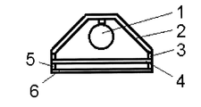
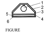
- the FIGURE shows the apparatus according to the invention by way of example.
- the apparatus comprises a radiation source ( 1 ) having a maximum radiative power in the wavelength range of 0.78-2.5 ⁇ m.
- the radiation source is surrounded by a housing ( 2 ), the inner surface of which (surface facing the radiation source) has a low absorbance.
- On one side of the housing ( 2 ) is an opening in which there is a screen ( 4 ) having a high absorbance.
- the screen ( 4 ) and housing ( 2 ) are preferably thermally decoupled by means of an insulator ( 3 ).
- the apparatus according to the invention has a transparent guard plate ( 6 ) in order to avoid direct contact between the screen and powder particles.
- the plate ( 6 ) and screen ( 4 ) are preferably thermally decoupled by means of an insulator ( 5 ).
- the heating of the powder particles can be conducted until fusion.
- the present invention likewise provides a method of heating polymeric powder particles, wherein the apparatus according to the invention is used. This involves exposing polymer powders to the radiation from the apparatus.
- the powder particles are preferably heated at a heating rate of at least 2 K/s, preferably at least 10 K/s, and more preferably at least 20 K/s.
- the change in temperature is measured with a pyrometer (optris CTfastLT) from Optris.
- the invention further provides for the use of the apparatus according to the invention for heating of polymer powder particles, preferably in powder coating methods.
- the apparatuses described in the examples were used to heat powders.
- an uncoloured nylon-12 powder having the characteristics listed in Table 1 was used.
- the experiments were conducted under standard climatic conditions (23° C./50%).
- the radiation sources had a power rating of 500 W.
- a flat powder layer of thickness 0.5 mm was applied to a plate of polished steel.
- the radiative heaters were positioned at a distance of 20 mm above the powder surface.
- the powder, the metal plate and the radiative heaters were conditioned under the standard climatic conditions for 2 h before the measurement was started.
- the radiative heaters were switched on and the time taken for the powder to start to melt was measured.
- a halogen radiation source comprising a halogen lamp as radiation source, a housing and a guard plate had its maximum radiative power in the wavelength range of 0.78-2.5 ⁇ m.
- a ceramic radiation source had its maximum radiative power in the IR-C wavelength range (3-1000 ⁇ m).
- the halogen radiation source from Example 1 had a screen made from oxidized steel sheet with a thickness of 0.5 mm and with an absorbance of more than 0.88 in the wavelength range of 0.78-2.5 ⁇ m.
- the halogen radiation source from Example 1 had a screen made from eloxed and black-coloured aluminium sheet with a thickness of 0.3 mm and with an absorbance of more than 0.95 in the wavelength range of 0.78-2.5 ⁇ m.
- the apparatuses according to the invention from Examples 3 and 4 required a much shorter time to melt the powder.
- applications such as electrostatic coating or mini-coating, for example, or in the powder-based methods specified in ISO/ASTM 52900, it is possible to achieve distinct acceleration of the process and hence of productivity. Moreover, a smaller amount of energy is also required to melt the powder.
- the apparatus according to the invention thus enables thicker powder layers, or heating or melting of multiple layers.
- German patent application 102016219182.9 filed Oct. 4, 2016 and German patent application 102017203523.4 filed Mar. 3, 2017, are incorporated herein by reference.
Landscapes
- Chemical & Material Sciences (AREA)
- Life Sciences & Earth Sciences (AREA)
- Engineering & Computer Science (AREA)
- Materials Engineering (AREA)
- Wood Science & Technology (AREA)
- Organic Chemistry (AREA)
- Chemical Kinetics & Catalysis (AREA)
- Application Of Or Painting With Fluid Materials (AREA)
- Paints Or Removers (AREA)
- Processing And Handling Of Plastics And Other Materials For Molding In General (AREA)
- Resistance Heating (AREA)
- Processes Of Treating Macromolecular Substances (AREA)
Abstract
Description
- The present invention relates to an apparatus for heating polymeric powders by means of radiation in powder coating methods, to a method of heating the powders and to the use of the apparatus.
- The powder particles used for powder coating generally consist of dry, grainy particles having a diameter between 1 and 140 μm. In chemical terms, these are usually based on epoxy resins or polyester resins. In addition, hybrid systems containing both epoxy resins and polyester resins as binder are in wide use. Powder particles based on thermoplastic polymers are likewise frequently used.
- The state of the art is electrostatic application of the powder particles. In electrostatic powder coating, the first step is to generate a cloud of electrically charged powder. The particles of like charge are transported to the workpiece surface. They are precipitated at the surface, adhere there electrostatically and form the powder coating layer. Charging is possible by corona charging/ionization or by friction. The fusion and/or crosslinking of the powder particles is typically effected by heating in an oven through convection. Heating by convection sometimes takes a relatively long time, and so the charging of the particles declines and adhesion decreases. In this case, the particles can simply fall off before there is any fusion or crosslinking. There is a distinct decrease in the quality of the coating in this case. The powder particles can also be heated by means of electromagnetic radiation. This has the advantage that the fusion/crosslinking can be much quicker. One problem, however, is that many uncoloured polymers have only very poor absorbance of electromagnetic radiation in the visible and near infrared (IR-A) wavelength range (0.78-1.4 μm), or the absorbance is highly dependent on the colouring of the polymer particles. In the case of the uncoloured polymer particles, owing to the poor absorbance, a significant portion of the radiative energy is not utilized. In the case of coloured polymers, the amount of radiation always has to be matched to the particular colour of the polymer. A further drawback of the current prior art is the possible contact of powder particles with hot surfaces and the associated elevated risk of dust explosions.
- For the heating of the polymeric powder particles, therefore, an advantageous radiation source is one that releases most of its radiation within the wavelength range of (2.5-10 μm). Radiative heaters such as ceramic radiation sources fulfil this requirement, but are very sluggish with regard to temperature regulation. Therefore, for many applications, there is a requirement for a radiation source that has its radiation maximum in the wavelength range of 2.5 to 10 μm and can be regulated quickly with regard to radiation intensity.
- Accordingly, the problem addressed was that of providing an apparatus which is suitable for the heating of polymeric powder particles but does not have the disadvantages of the prior art. More particularly, the apparatus should have a radiation maximum in the wavelength range of 2.5-10 μm and enable a rapid change in the radiation intensity and hence a rapid change in temperature.
- The present invention relates to an apparatus for heating polymer powder particles, comprising:
- a radiation source,
- a housing, and
- a screen,
- wherein the radiation source has its maximum radiation power within the wavelength range of 0.78-2.5 μm and the screen has an absorbance of at least 0.8 within the wavelength range of 0.78-2.5 μm.
- The present invention further relates to a method of heating polymer powder particles, said method comprising:
- heating the polymer powder particles with an apparatus according to
claim 1, wherein the polymer powder particles are exposed to the radiation from the apparatus. - In addition, the present invention relates to a method of coating a powder, said method comprising:
- heating of polymer powder particles.
- The FIGURE shows the apparatus according to the invention by way of example.
- Accordingly, an apparatus of the type specified at the outset has been found, comprising a radiation source, a housing and a screen. The radiation source of the apparatus has its maximum radiative power in the wavelength range of 0.78-2.5 μm. The term “in the wavelength range” or “in the overall wavelength range” in respect of the radiation source is understood such that the radiation source has a maximum radiative power at at least one wavelength in the wavelength range specified. The screen has an absorbance of at least 0.8 in the wavelength range of 0.78-2.5 μm. The term “in the wavelength range” or “in the overall wavelength range” in respect of the screen is understood such that the screen has at least the absorbance specified at all wavelengths in the wavelength range specified. The screen is preferably aligned at right angles to the radiation source within the housing. With regard to the polymer powder particles to be heated, the screen is preferably aligned in parallel.
- It has been found that, surprisingly, in the form of the apparatus according to the invention, an apparatus can be provided as a radiative heater which can generate radiation necessary for the efficient heating of polymeric powder particles and at the same time can be regulated quickly in terms of intensity and temperature. The particles are not heated directly by the radiation source, but by the screen. The screen absorbs the radiative energy from the radiation source and releases the energy in a shifted wavelength range. The radiation maximum of the apparatus according to the invention is accordingly preferably at a wavelength of more than 2.5 μm and below 4.8 μm, preferably between 3.1 μm and 4.2 m.
- Suitable radiation sources are IR-A radiation sources (wavelengths of 0.78 to 1.4 μm) such as halogen lamps or NIR lasers (NIR=near infrared).
- The screen, over the entire wavelength range of 0.78-2.5 μm, has an absorbance of at least 0.8, preferably at least 0.9 and more preferably at least 0.95. The thickness of the screen is preferably not more than 1 mm. The thickness is preferably not more than 0.5 mm, more preferably not more than 0.3 mm and most preferably not more than 0.1 mm.
- The screen should preferably have a low heat capacity. As a result, the screen reacts relatively quickly to changes in the radiation intensity of the radiation source. This enables a rapid change in temperature of the apparatus.
- Examples of suitable materials for the screen are selected from oxidized metals such as steel sheets, aluminium, copper or silver sheets, graphite, silicon, surface-treated and/or coloured ceramics, mineral fibres and coloured glasses, preference being given to eloxed and coloured, especially black-coloured, aluminium. Combinations of the materials mentioned are also possible.
- The radiation source is surrounded by a housing, the surfaces of which that face the radiation source preferably have a low absorbance of less than 0.4 in the wavelength range of 0.78-2.5 μm, more preferably less than 0.3. The housing has at least one opening in the direction of the screen. Examples of suitable materials for the housing are metals, preferably having a polished surface (Rz according to DIN EN ISO 4287 of max. 2 μm), metallized ceramics and ceramics having low absorbance (less than 0.4 in the wavelength range of 0.78-2.5 μm). The term “in the wavelength range” or “in the overall wavelength range” in respect of the housing is understood such that the housing has a lower absorbance than that specified at all wavelengths in the wavelength range specified.
- In a preferred embodiment, the apparatus according to the invention additionally comprises a guard plate. In this case, the screen is arranged between the radiation source and the guard plate. The guard plate prevents direct contact of the heated screen with the polymeric powder particles. The guard plate may be transparent. The transmittance of the guard plate in the wavelength range of 2.5-4.8 μm is preferably at least 0.9. The guard plate may be selected, for example, from chalcogenide glass and sapphire glass. The term “in the wavelength range” or “in the overall wavelength range” in respect of the guard plate is understood such that the guard plate has at least the transmittance specified at all wavelengths in the wavelength range specified.
- With the combination of multiple apparatuses according to the invention, it is possible also to heat greater areas. If these apparatuses are regulated differently, it is possible to match the temperature distribution on the surface to be heated to the technical requirements. In a further alternative embodiment, multiple radiation sources are combined with a screen in order to heat greater areas.
- The housing and screen are preferably thermally decoupled. If a guard plate is included, it is preferable that the housing, screen and guard plate are thermally decoupled from one another.
- The absorbance and the transmittance are determined by means of a Cary 5000 UV-vis/NIR spectrophotometer from Varian to DIN EN ISO 13468-2:2006-07. The measurement takes place under standard conditions (23° C./50%).
- Examples of suitable polymers which can be processed by means of the apparatus according to the invention are polyamides such as nylon-6, nylon-11 or nylon-12, copolyamides such as nylon-4,6, nylon-6,6, nylon-6,13, nylon-10,6, nylon-10,10, nylon-10,12, nylon-12,12, nylon-10,13, nylon-12/10,12, polyolefins such as polyethylene and polypropylene, polyesters, and polyaryl ether ketones (PEAKs) such as polyether ether ketone.
- The FIGURE shows the apparatus according to the invention by way of example. The apparatus comprises a radiation source (1) having a maximum radiative power in the wavelength range of 0.78-2.5 μm. The radiation source is surrounded by a housing (2), the inner surface of which (surface facing the radiation source) has a low absorbance. On one side of the housing (2) is an opening in which there is a screen (4) having a high absorbance. The screen (4) and housing (2) are preferably thermally decoupled by means of an insulator (3). Preferably, the apparatus according to the invention has a transparent guard plate (6) in order to avoid direct contact between the screen and powder particles. The plate (6) and screen (4) are preferably thermally decoupled by means of an insulator (5).
- The heating of the powder particles can be conducted until fusion.
- The present invention likewise provides a method of heating polymeric powder particles, wherein the apparatus according to the invention is used. This involves exposing polymer powders to the radiation from the apparatus. The powder particles are preferably heated at a heating rate of at least 2 K/s, preferably at least 10 K/s, and more preferably at least 20 K/s. The change in temperature is measured with a pyrometer (optris CTfastLT) from Optris.
- The invention further provides for the use of the apparatus according to the invention for heating of polymer powder particles, preferably in powder coating methods.
- Having generally described this invention, a further understanding can be obtained by reference to certain specific examples which are provided herein for purposes of illustration only, and are not intended to be limiting unless otherwise specified.
- The apparatuses described in the examples were used to heat powders. For the experiments, an uncoloured nylon-12 powder having the characteristics listed in Table 1 was used. The experiments were conducted under standard climatic conditions (23° C./50%). The radiation sources had a power rating of 500 W. In all the examples, a flat powder layer of thickness 0.5 mm was applied to a plate of polished steel. The radiative heaters were positioned at a distance of 20 mm above the powder surface. The powder, the metal plate and the radiative heaters were conditioned under the standard climatic conditions for 2 h before the measurement was started. In the examples, the radiative heaters were switched on and the time taken for the powder to start to melt was measured.
- A halogen radiation source comprising a halogen lamp as radiation source, a housing and a guard plate had its maximum radiative power in the wavelength range of 0.78-2.5 μm.
- A ceramic radiation source had its maximum radiative power in the IR-C wavelength range (3-1000 μm).
- The halogen radiation source from Example 1 had a screen made from oxidized steel sheet with a thickness of 0.5 mm and with an absorbance of more than 0.88 in the wavelength range of 0.78-2.5 μm.
- The halogen radiation source from Example 1 had a screen made from eloxed and black-coloured aluminium sheet with a thickness of 0.3 mm and with an absorbance of more than 0.95 in the wavelength range of 0.78-2.5 μm.
-
TABLE 1 Powder characteristics of the nylon-12 used Value Unit Test type/test instrument/test parameter Bulk density 0.450 g/cm3 DIN EN ISO 60 Particle 57 μm Malvern Mastersizer 2000, dry mea- size d50 surement, metered addition of 20-40 g of powder using Scirocco dry dispersion instrument. Vibratory trough feed rate 70%, dispersing air pressure 3 bar.Sample residence time 5 seconds (5000 individual measurements), refractive index and blue light value fixed at 1.52. Evaluation by Mie theory. Particle 36 μm Malvern Mastersizer 2000, see size d10 particle size d50 for parameters Particle 82 μm Malvern Mastersizer 2000, see size d90 particle size d50 for parameters <10.48 μm 1.4 % Malvern Mastersizer 2000, see particle size d50 for parameters Flowability 28 s DIN EN ISO 6186, Method A, diam- eter of nozzle outlet 15 mm Solution 1.58 — ISO 307, Schort AVS Pro, solvent: viscosity acidified m-cresol, volumetric method, double determination, dissolution temperature 100° C., dissolution time 2 h, polymer concentration 5 g/l Measurement temperature 25° C. BET (spec. 6.7 m2/g ISO 9277, Micromeritics TriStar surface area) 3000, nitrogen gas adsorption, discontinuous volumetric method, 7 data points at relative pressures P/P0 from about 0.05 to about 0.20, dead volume calibration using He (99.996%), sample preparation 1 h at 23° C. + 16 h at 80° C. in vacuo, spec. surface area based on the devola- tilized sample, evaluation by means of multipoint determination Melting point, 187 ° C. DIN 53765 Perkin Elmer DSC 7 1st heating heating/cooling rate 20 K/min Recrystal- 142 ° C. DIN 53765 Perkin Elmer DSC 7 lization heating/cooling rate 20 K/min temperature Material Material stored for 24 h at 23° C. and 50% humidity conditioning prior to processing/analysis -
TABLE 2 Experimental results Exam- Exam- Exam- Exam- ple 1ple 2ple 3ple 4Time required for the 491 151 84 73 powder to start to melt in s - The apparatuses according to the invention from Examples 3 and 4 required a much shorter time to melt the powder. In applications such as electrostatic coating or mini-coating, for example, or in the powder-based methods specified in ISO/ASTM 52900, it is possible to achieve distinct acceleration of the process and hence of productivity. Moreover, a smaller amount of energy is also required to melt the powder. The apparatus according to the invention thus enables thicker powder layers, or heating or melting of multiple layers.
- German patent application 102016219182.9 filed Oct. 4, 2016 and German patent application 102017203523.4 filed Mar. 3, 2017, are incorporated herein by reference.
- Numerous modifications and variations on the present invention are possible in light of the above teachings. It is therefore to be understood that within the scope of the appended claims, the invention may be practiced otherwise than as specifically described herein.
Claims (10)
Applications Claiming Priority (6)
| Application Number | Priority Date | Filing Date | Title |
|---|---|---|---|
| DE102016219182 | 2016-10-04 | ||
| DE102016219182.9 | 2016-10-04 | ||
| DE102016219182 | 2016-10-04 | ||
| DE102017203523.4 | 2017-03-03 | ||
| DE102017203523 | 2017-03-03 | ||
| DE102017203523.4A DE102017203523A1 (en) | 2016-10-04 | 2017-03-03 | Apparatus for heating polymeric powders by radiation in powder coating processes |
Publications (2)
| Publication Number | Publication Date |
|---|---|
| US20180098384A1 true US20180098384A1 (en) | 2018-04-05 |
| US10356849B2 US10356849B2 (en) | 2019-07-16 |
Family
ID=59010816
Family Applications (1)
| Application Number | Title | Priority Date | Filing Date |
|---|---|---|---|
| US15/705,052 Active 2038-01-31 US10356849B2 (en) | 2016-10-04 | 2017-09-14 | Apparatus for heating polymeric powders by means of radiation in powder coating methods |
Country Status (7)
| Country | Link |
|---|---|
| US (1) | US10356849B2 (en) |
| EP (1) | EP3305418B1 (en) |
| JP (1) | JP6538794B2 (en) |
| CN (1) | CN107890974B (en) |
| DE (1) | DE102017203523A1 (en) |
| ES (1) | ES2934740T3 (en) |
| PL (1) | PL3305418T3 (en) |
Cited By (4)
| Publication number | Priority date | Publication date | Assignee | Title |
|---|---|---|---|---|
| CN113064146A (en) * | 2021-04-23 | 2021-07-02 | 沈阳工程学院 | Protection device for wind power prediction sodar and control method |
| GB2580040B (en) * | 2018-12-19 | 2022-01-19 | Stratasys Powder Production Ltd | Heater arrangements and apparatus for layer-by-layer formation of three-dimensional objects |
| US11511488B2 (en) | 2017-12-22 | 2022-11-29 | Evonik Operations Gmbh | Device for producing three-dimensional objects layer by layer |
| US12605909B2 (en) | 2019-02-21 | 2026-04-21 | Evonik Operations Gmbh | Process for the surface treatment of polymeric three-dimensional objects |
Citations (4)
| Publication number | Priority date | Publication date | Assignee | Title |
|---|---|---|---|---|
| US4521487A (en) * | 1983-09-21 | 1985-06-04 | Sumitomo Chemical Company, Limited | Particulate polyolefin expansion molding material |
| US4870118A (en) * | 1985-11-11 | 1989-09-26 | Dainippon Ink And Chemicals, Inc. | Powdery copolymers of vinyl ester-ethylene |
| US6787233B1 (en) * | 1998-10-19 | 2004-09-07 | Dynal Biotech Asa | Particles |
| US20120220746A1 (en) * | 2008-03-31 | 2012-08-30 | Techno Polymer Co., Ltd. | Process for producing thermoplastic resin molded product and thermoplastic resin particle composition |
Family Cites Families (11)
| Publication number | Priority date | Publication date | Assignee | Title |
|---|---|---|---|---|
| JP2978716B2 (en) * | 1994-04-22 | 1999-11-15 | ウシオ電機株式会社 | Far infrared heater |
| JPH08285694A (en) * | 1995-04-18 | 1996-11-01 | Nikon Corp | Infrared imaging device |
| SE509088C2 (en) * | 1997-04-30 | 1998-12-07 | Ralf Larsson | Methods and apparatus for the production of volume bodies |
| JP2002143748A (en) | 2000-11-08 | 2002-05-21 | Inoac Corp | Coating system |
| JP4263529B2 (en) | 2003-05-14 | 2009-05-13 | 日本電熱株式会社 | Heating device |
| DE10352184A1 (en) * | 2003-11-05 | 2005-06-23 | Arccure Technologies Gmbh | Apparatus for curing or drying coatings on substrates comprises lamp above substrate fitted with curved barrier immediately below it, curved reflection filters behind it and straight filters across part of light outlet |
| DE102009011361A1 (en) | 2009-03-05 | 2010-09-09 | Krones Ag | Oven for plastic preforms with semi-transparent spotlight |
| JP5797413B2 (en) | 2011-01-25 | 2015-10-21 | 光洋サーモシステム株式会社 | Heater unit and heat treatment apparatus |
| JP5694983B2 (en) * | 2012-03-27 | 2015-04-01 | 日本碍子株式会社 | Infrared heater |
| CN104811247A (en) * | 2014-01-23 | 2015-07-29 | 温成 | Invisible light emitting device |
| DE102016205053A1 (en) | 2016-03-24 | 2017-09-28 | Evonik Degussa Gmbh | Process for melting / sintering powder particles for the layered production of three-dimensional objects |
-
2017
- 2017-03-03 DE DE102017203523.4A patent/DE102017203523A1/en not_active Withdrawn
- 2017-09-05 PL PL17189424.9T patent/PL3305418T3/en unknown
- 2017-09-05 ES ES17189424T patent/ES2934740T3/en active Active
- 2017-09-05 EP EP17189424.9A patent/EP3305418B1/en active Active
- 2017-09-14 US US15/705,052 patent/US10356849B2/en active Active
- 2017-09-29 CN CN201710907262.XA patent/CN107890974B/en active Active
- 2017-10-04 JP JP2017194280A patent/JP6538794B2/en active Active
Patent Citations (4)
| Publication number | Priority date | Publication date | Assignee | Title |
|---|---|---|---|---|
| US4521487A (en) * | 1983-09-21 | 1985-06-04 | Sumitomo Chemical Company, Limited | Particulate polyolefin expansion molding material |
| US4870118A (en) * | 1985-11-11 | 1989-09-26 | Dainippon Ink And Chemicals, Inc. | Powdery copolymers of vinyl ester-ethylene |
| US6787233B1 (en) * | 1998-10-19 | 2004-09-07 | Dynal Biotech Asa | Particles |
| US20120220746A1 (en) * | 2008-03-31 | 2012-08-30 | Techno Polymer Co., Ltd. | Process for producing thermoplastic resin molded product and thermoplastic resin particle composition |
Cited By (4)
| Publication number | Priority date | Publication date | Assignee | Title |
|---|---|---|---|---|
| US11511488B2 (en) | 2017-12-22 | 2022-11-29 | Evonik Operations Gmbh | Device for producing three-dimensional objects layer by layer |
| GB2580040B (en) * | 2018-12-19 | 2022-01-19 | Stratasys Powder Production Ltd | Heater arrangements and apparatus for layer-by-layer formation of three-dimensional objects |
| US12605909B2 (en) | 2019-02-21 | 2026-04-21 | Evonik Operations Gmbh | Process for the surface treatment of polymeric three-dimensional objects |
| CN113064146A (en) * | 2021-04-23 | 2021-07-02 | 沈阳工程学院 | Protection device for wind power prediction sodar and control method |
Also Published As
| Publication number | Publication date |
|---|---|
| EP3305418B1 (en) | 2022-11-02 |
| JP6538794B2 (en) | 2019-07-03 |
| US10356849B2 (en) | 2019-07-16 |
| DE102017203523A1 (en) | 2017-06-29 |
| CN107890974B (en) | 2022-07-19 |
| PL3305418T3 (en) | 2023-04-11 |
| EP3305418A1 (en) | 2018-04-11 |
| ES2934740T3 (en) | 2023-02-24 |
| JP2018060793A (en) | 2018-04-12 |
| CN107890974A (en) | 2018-04-10 |
Similar Documents
| Publication | Publication Date | Title |
|---|---|---|
| US10356849B2 (en) | Apparatus for heating polymeric powders by means of radiation in powder coating methods | |
| US20220168956A1 (en) | Process and apparatus for producing 3d moldings comprising a spectrum converter | |
| US20020033134A1 (en) | Method and apparatus for processing coatings, radiation curable coatings on wood, wood composite and other various substrates | |
| EP3371259A1 (en) | A method for producing a reflective photoluminescent coating, and the reflective photoluminescent powder paint | |
| CN108375888B (en) | Addition-curable liquid silicone rubber mixture, electrophotographic member, method for producing same, and fixing device | |
| Sonawane et al. | Effects of cold atmospheric plasma treatment on the morphological and optical properties of plasmonic silver nanoparticles | |
| US4341819A (en) | Epoxy coating powders with wrinkle finishes | |
| JP2022104863A (en) | Ethylene vinyl alcohol copolymer and production method of the same | |
| CN107903788A (en) | The preparation method of the even heat-insulation composite material of high-performance | |
| CN110087867A (en) | Flexible substrates and preparation method thereof with plasma particle surface covering | |
| Nowak et al. | Kinetics of melamine phosphate thermal decomposition in DSC studies | |
| US20060201917A1 (en) | Process for monitoring and controlling of thermal spray process | |
| EP1539377B1 (en) | Process for curing powder coatings | |
| JPH02243580A (en) | Ceramic powder for electrostatic powder coating and manufacture of said powder | |
| CN109365237B (en) | Powder coating curing method | |
| Maurer et al. | Rapid bonding of non-metallic materials: Bonding and sealing via induction curing | |
| CN105862443A (en) | Balloon bag material for fire balloon and preparation method of balloon bag material | |
| Yurasov | POWDER COMPOSITIONS AND COATING PROCESS TECHNOLOGIES BASED ON THEM | |
| KR20030007593A (en) | Method and arrangement for the production of a thin layered structure | |
| WO2002023107A2 (en) | Method and apparatus for processing coatings, radiation curable coatings on wood, wood composite and other various substrates | |
| Li et al. | Radiative Cooling Coating by Using Porous PE with PDMS Nanoparticles | |
| WO2025195876A1 (en) | Powder coating compositions | |
| JPS6363506B2 (en) | ||
| Doppner et al. | Electron-ion temperature equilibration in warm dense tantalum | |
| CN107900363A (en) | A kind of 3D printer aluminium powder and preparation method thereof |
Legal Events
| Date | Code | Title | Description |
|---|---|---|---|
| FEPP | Fee payment procedure |
Free format text: ENTITY STATUS SET TO UNDISCOUNTED (ORIGINAL EVENT CODE: BIG.); ENTITY STATUS OF PATENT OWNER: LARGE ENTITY |
|
| AS | Assignment |
Owner name: EVONIK DEGUSSA GMBH, GERMANY Free format text: ASSIGNMENT OF ASSIGNORS INTEREST;ASSIGNORS:GREBE, MAIK;DIEKMANN, WOLFGANG;BAPTISTA, ANDREAS;SIGNING DATES FROM 20180212 TO 20180228;REEL/FRAME:046401/0276 |
|
| STPP | Information on status: patent application and granting procedure in general |
Free format text: NON FINAL ACTION MAILED |
|
| STPP | Information on status: patent application and granting procedure in general |
Free format text: PUBLICATIONS -- ISSUE FEE PAYMENT VERIFIED |
|
| STPP | Information on status: patent application and granting procedure in general |
Free format text: AWAITING TC RESP, ISSUE FEE PAYMENT VERIFIED Free format text: PUBLICATIONS -- ISSUE FEE PAYMENT VERIFIED |
|
| STCF | Information on status: patent grant |
Free format text: PATENTED CASE |
|
| AS | Assignment |
Owner name: EVONIK OPERATIONS GMBH, GERMANY Free format text: CHANGE OF NAME;ASSIGNOR:EVONIK DEGUSSA GMBH;REEL/FRAME:051045/0872 Effective date: 20191104 |
|
| MAFP | Maintenance fee payment |
Free format text: PAYMENT OF MAINTENANCE FEE, 4TH YEAR, LARGE ENTITY (ORIGINAL EVENT CODE: M1551); ENTITY STATUS OF PATENT OWNER: LARGE ENTITY Year of fee payment: 4 |