EP3303074B1 - Procédé et dispositif de régulation électronique d'un système de ralentissement de véhicule en fonction d'une différence de glissement entre deux essieux de véhicule - Google Patents
Procédé et dispositif de régulation électronique d'un système de ralentissement de véhicule en fonction d'une différence de glissement entre deux essieux de véhicule Download PDFInfo
- Publication number
- EP3303074B1 EP3303074B1 EP16719211.1A EP16719211A EP3303074B1 EP 3303074 B1 EP3303074 B1 EP 3303074B1 EP 16719211 A EP16719211 A EP 16719211A EP 3303074 B1 EP3303074 B1 EP 3303074B1
- Authority
- EP
- European Patent Office
- Prior art keywords
- vehicle
- deceleration
- axle
- actual
- differential slip
- Prior art date
- Legal status (The legal status is an assumption and is not a legal conclusion. Google has not performed a legal analysis and makes no representation as to the accuracy of the status listed.)
- Active
Links
- 238000000034 method Methods 0.000 title claims description 44
- 239000008186 active pharmaceutical agent Substances 0.000 claims description 129
- 230000001419 dependent effect Effects 0.000 claims description 22
- 230000000694 effects Effects 0.000 claims description 15
- 230000008569 process Effects 0.000 claims description 13
- 230000007423 decrease Effects 0.000 claims description 8
- 230000001360 synchronised effect Effects 0.000 claims description 6
- HRJXKKSJPNWKCP-UNXDAHLPSA-N (1E,2Z)-3-hydroxy-5,9,17-trioxo-4,5:9,10-disecoandrosta-1(10),2-dien-4-oic acid Chemical compound C1CC(=O)[C@@H](CCC(=O)C(=C/C=C(\O)C(O)=O)/C)[C@@H]2CCC(=O)[C@]21C HRJXKKSJPNWKCP-UNXDAHLPSA-N 0.000 claims 2
- 238000004364 calculation method Methods 0.000 description 10
- 230000001105 regulatory effect Effects 0.000 description 10
- 230000003111 delayed effect Effects 0.000 description 7
- 230000004044 response Effects 0.000 description 7
- 230000001133 acceleration Effects 0.000 description 6
- 238000006073 displacement reaction Methods 0.000 description 6
- 230000001934 delay Effects 0.000 description 5
- 238000010586 diagram Methods 0.000 description 5
- 230000000903 blocking effect Effects 0.000 description 4
- 230000001276 controlling effect Effects 0.000 description 4
- 230000003247 decreasing effect Effects 0.000 description 4
- 230000000630 rising effect Effects 0.000 description 4
- 230000009471 action Effects 0.000 description 3
- 230000008859 change Effects 0.000 description 3
- 239000000725 suspension Substances 0.000 description 3
- 206010038743 Restlessness Diseases 0.000 description 2
- 230000033228 biological regulation Effects 0.000 description 2
- 238000009795 derivation Methods 0.000 description 2
- 230000005484 gravity Effects 0.000 description 2
- 238000005259 measurement Methods 0.000 description 2
- 230000009467 reduction Effects 0.000 description 2
- 230000007704 transition Effects 0.000 description 2
- 230000004913 activation Effects 0.000 description 1
- 230000008901 benefit Effects 0.000 description 1
- 230000001914 calming effect Effects 0.000 description 1
- 238000001514 detection method Methods 0.000 description 1
- 238000011161 development Methods 0.000 description 1
- 230000018109 developmental process Effects 0.000 description 1
- 239000012530 fluid Substances 0.000 description 1
- 230000001404 mediated effect Effects 0.000 description 1
- 230000008092 positive effect Effects 0.000 description 1
- 238000005096 rolling process Methods 0.000 description 1
- 238000013022 venting Methods 0.000 description 1
Images


Classifications
-
- B—PERFORMING OPERATIONS; TRANSPORTING
- B60—VEHICLES IN GENERAL
- B60T—VEHICLE BRAKE CONTROL SYSTEMS OR PARTS THEREOF; BRAKE CONTROL SYSTEMS OR PARTS THEREOF, IN GENERAL; ARRANGEMENT OF BRAKING ELEMENTS ON VEHICLES IN GENERAL; PORTABLE DEVICES FOR PREVENTING UNWANTED MOVEMENT OF VEHICLES; VEHICLE MODIFICATIONS TO FACILITATE COOLING OF BRAKES
- B60T8/00—Arrangements for adjusting wheel-braking force to meet varying vehicular or ground-surface conditions, e.g. limiting or varying distribution of braking force
- B60T8/17—Using electrical or electronic regulation means to control braking
- B60T8/1701—Braking or traction control means specially adapted for particular types of vehicles
- B60T8/1708—Braking or traction control means specially adapted for particular types of vehicles for lorries or tractor-trailer combinations
-
- B—PERFORMING OPERATIONS; TRANSPORTING
- B60—VEHICLES IN GENERAL
- B60T—VEHICLE BRAKE CONTROL SYSTEMS OR PARTS THEREOF; BRAKE CONTROL SYSTEMS OR PARTS THEREOF, IN GENERAL; ARRANGEMENT OF BRAKING ELEMENTS ON VEHICLES IN GENERAL; PORTABLE DEVICES FOR PREVENTING UNWANTED MOVEMENT OF VEHICLES; VEHICLE MODIFICATIONS TO FACILITATE COOLING OF BRAKES
- B60T13/00—Transmitting braking action from initiating means to ultimate brake actuator with power assistance or drive; Brake systems incorporating such transmitting means, e.g. air-pressure brake systems
- B60T13/10—Transmitting braking action from initiating means to ultimate brake actuator with power assistance or drive; Brake systems incorporating such transmitting means, e.g. air-pressure brake systems with fluid assistance, drive, or release
-
- B—PERFORMING OPERATIONS; TRANSPORTING
- B60—VEHICLES IN GENERAL
- B60T—VEHICLE BRAKE CONTROL SYSTEMS OR PARTS THEREOF; BRAKE CONTROL SYSTEMS OR PARTS THEREOF, IN GENERAL; ARRANGEMENT OF BRAKING ELEMENTS ON VEHICLES IN GENERAL; PORTABLE DEVICES FOR PREVENTING UNWANTED MOVEMENT OF VEHICLES; VEHICLE MODIFICATIONS TO FACILITATE COOLING OF BRAKES
- B60T8/00—Arrangements for adjusting wheel-braking force to meet varying vehicular or ground-surface conditions, e.g. limiting or varying distribution of braking force
- B60T8/17—Using electrical or electronic regulation means to control braking
- B60T8/176—Brake regulation specially adapted to prevent excessive wheel slip during vehicle deceleration, e.g. ABS
- B60T8/1766—Proportioning of brake forces according to vehicle axle loads, e.g. front to rear of vehicle
-
- B—PERFORMING OPERATIONS; TRANSPORTING
- B60—VEHICLES IN GENERAL
- B60T—VEHICLE BRAKE CONTROL SYSTEMS OR PARTS THEREOF; BRAKE CONTROL SYSTEMS OR PARTS THEREOF, IN GENERAL; ARRANGEMENT OF BRAKING ELEMENTS ON VEHICLES IN GENERAL; PORTABLE DEVICES FOR PREVENTING UNWANTED MOVEMENT OF VEHICLES; VEHICLE MODIFICATIONS TO FACILITATE COOLING OF BRAKES
- B60T8/00—Arrangements for adjusting wheel-braking force to meet varying vehicular or ground-surface conditions, e.g. limiting or varying distribution of braking force
- B60T8/26—Arrangements for adjusting wheel-braking force to meet varying vehicular or ground-surface conditions, e.g. limiting or varying distribution of braking force characterised by producing differential braking between front and rear wheels
- B60T8/266—Arrangements for adjusting wheel-braking force to meet varying vehicular or ground-surface conditions, e.g. limiting or varying distribution of braking force characterised by producing differential braking between front and rear wheels using valves or actuators with external control means
- B60T8/268—Arrangements for adjusting wheel-braking force to meet varying vehicular or ground-surface conditions, e.g. limiting or varying distribution of braking force characterised by producing differential braking between front and rear wheels using valves or actuators with external control means using the valves of an ABS, ASR or ESP system
-
- B—PERFORMING OPERATIONS; TRANSPORTING
- B60—VEHICLES IN GENERAL
- B60T—VEHICLE BRAKE CONTROL SYSTEMS OR PARTS THEREOF; BRAKE CONTROL SYSTEMS OR PARTS THEREOF, IN GENERAL; ARRANGEMENT OF BRAKING ELEMENTS ON VEHICLES IN GENERAL; PORTABLE DEVICES FOR PREVENTING UNWANTED MOVEMENT OF VEHICLES; VEHICLE MODIFICATIONS TO FACILITATE COOLING OF BRAKES
- B60T8/00—Arrangements for adjusting wheel-braking force to meet varying vehicular or ground-surface conditions, e.g. limiting or varying distribution of braking force
- B60T8/32—Arrangements for adjusting wheel-braking force to meet varying vehicular or ground-surface conditions, e.g. limiting or varying distribution of braking force responsive to a speed condition, e.g. acceleration or deceleration
- B60T8/321—Arrangements for adjusting wheel-braking force to meet varying vehicular or ground-surface conditions, e.g. limiting or varying distribution of braking force responsive to a speed condition, e.g. acceleration or deceleration deceleration
- B60T8/3255—Systems in which the braking action is dependent on brake pedal data
- B60T8/327—Pneumatic systems
-
- B—PERFORMING OPERATIONS; TRANSPORTING
- B60—VEHICLES IN GENERAL
- B60T—VEHICLE BRAKE CONTROL SYSTEMS OR PARTS THEREOF; BRAKE CONTROL SYSTEMS OR PARTS THEREOF, IN GENERAL; ARRANGEMENT OF BRAKING ELEMENTS ON VEHICLES IN GENERAL; PORTABLE DEVICES FOR PREVENTING UNWANTED MOVEMENT OF VEHICLES; VEHICLE MODIFICATIONS TO FACILITATE COOLING OF BRAKES
- B60T13/00—Transmitting braking action from initiating means to ultimate brake actuator with power assistance or drive; Brake systems incorporating such transmitting means, e.g. air-pressure brake systems
- B60T13/10—Transmitting braking action from initiating means to ultimate brake actuator with power assistance or drive; Brake systems incorporating such transmitting means, e.g. air-pressure brake systems with fluid assistance, drive, or release
- B60T13/58—Combined or convertible systems
- B60T13/585—Combined or convertible systems comprising friction brakes and retarders
-
- B—PERFORMING OPERATIONS; TRANSPORTING
- B60—VEHICLES IN GENERAL
- B60T—VEHICLE BRAKE CONTROL SYSTEMS OR PARTS THEREOF; BRAKE CONTROL SYSTEMS OR PARTS THEREOF, IN GENERAL; ARRANGEMENT OF BRAKING ELEMENTS ON VEHICLES IN GENERAL; PORTABLE DEVICES FOR PREVENTING UNWANTED MOVEMENT OF VEHICLES; VEHICLE MODIFICATIONS TO FACILITATE COOLING OF BRAKES
- B60T15/00—Construction arrangement, or operation of valves incorporated in power brake systems and not covered by groups B60T11/00 or B60T13/00
- B60T15/02—Application and release valves
- B60T15/025—Electrically controlled valves
Definitions
- the invention relates to a method for electronically regulating a vehicle deceleration in an ABS braking system, in particular in a commercial vehicle, by setting brake pressures on a vehicle axle to be controlled as a function of a detected actual differential slip and a device for carrying out the method.
- a brake pressure control that limits the brake pressure is used, in particular, to distribute the braking effect desired by a brake system or a driver in a suitable manner to the vehicle axles, so that the vehicle is preset in accordance with a driver Driver will or a vehicle target delay is delayed and remains stable at the same time depending on the driving situation. Because with a strong braking, d. H. at a high vehicle target deceleration, the vehicle weight is shifted to the front axle, so that rear wheels on the rear axle are pressed less strongly on the ground, whereby a blocking of the rear wheels is supported.
- EBL brake pressure control that limits the brake pressure
- the brake pressure By limiting the brake pressure to the wheel brakes of the rear wheels early braking of the rear wheels can be avoided during braking.
- the limitation of the brake pressure can be done in response to an axle load, as vehicles that are heavily loaded, more braking power can be brought to the road on the rear axle as in unladen vehicles in which an excessive braking of the rear wheels enhances the effect described above ; the blocking tendency of the rear wheels rises.
- a mechanical displacement sensor may be provided, which is deflected more or less depending on the load.
- a pressure sensor that measures the pressure in a bellows can be used for this purpose.
- the load-dependent measurement signal can be closed on the weight and depending on a limitation of the brake pressure can be made.
- an electronic brake pressure limitation may be provided in vehicles without such a mechanical displacement sensor or pressure sensor, in which no direct measurement of the load is provided.
- a control of the brake pressure to the wheel brakes of the rear wheels made. Since the difference in the wheel rotational speeds or the brake slip is load-dependent, the brake pressure is distributed according to the vehicle axles, to prevent the wheels of the rear axle early blockage and to delay the vehicle as intended.
- the DE 10 2008 009 948 B3 discloses an electronic brake pressure control in which the brake pressure is controlled at the wheel brakes in response to an axle load sensor and the vehicle target deceleration. If the axle load sensor fails, the brake pressure is regulated as a function of the difference between the brake slips on the vehicle axles, ie as a function of a measured actual differential slip.
- DE 10 2011 118 130 B4 also discloses an electronic brake pressure control, in which the braking forces in response to a determined actual differential slip or a determined differential speed of the wheels is distributed to the vehicle axles to delay the vehicle as intended.
- the brake pressure at the wheel brakes of the rear wheels is limited when the actual differential slip is exceeded via a desired differential slip.
- the desired differential slip is dependent on the vehicle target deceleration, the target differential slip increases at higher vehicle target delays to ensure a finer transition to an ABS control, which intervenes in the case rather than a constant running brake slip.
- the disadvantage here is that increasing the target differential slip at high vehicle target deceleration causes early activation of the ABS control, whereby the braking behavior is restless and uncertain, since the ABS control must intervene earlier.
- an electronic brake force distribution in which the braking forces are distributed to the vehicle axles as a function of the differential slip as a function of the vehicle deceleration.
- it is provided to measure a vehicle-actual deceleration and to regulate the brake pressure at the rear axle upon reaching a maximum deceleration, ie a specific threshold value for the vehicle-actual deceleration.
- the maximum deceleration is defined in such a way that, starting from this value, the rear wheels are more likely to lock than the front wheels.
- a tendency to lock the rear wheels is adapted to the tendency to lock the front wheels.
- a brake pressure at wheel brakes of a vehicle axle to be controlled of a vehicle as a function of a detected actual differential slip by limiting, preferably holding, the brake pressure at the wheel brakes of the vehicle axle to be controlled in order to overbrake the vehicle axle to be controlled relative to one avoid further vehicle axle.
- the actual differential slip is adjusted to a desired differential slip, wherein the desired differential slip is dependent on a detected actual vehicle deceleration and / or a detected vehicle nominal deceleration.
- the target differential slip decreases with increasing vehicle actual deceleration or vehicle target deceleration in the direction of a synchronous wheel rotational behavior of the wheels of the vehicle axle to be controlled and the further vehicle axle such that the vehicle axle to be controlled is blocked by the vehicle axle according to the invention early Counteracted procedure becomes; the brake pressure at the wheel brakes of the vehicle axle to be controlled is therefore already limited at a lower relative overbraking of the vehicle axle to be controlled; safety and braking comfort increase.
- the actual differential slip here gives a difference between a current rotational behavior of the vehicle axle to be controlled, e.g. a rear axle of the vehicle, to the other vehicle axle, e.g. a front axle of the vehicle, on.
- the rotational behavior is characterized by a brake slip or a rotational speed of the wheels of the corresponding vehicle axle.
- the actual differential slip thus indicates how much the vehicle axle to be controlled is over-braked or braked in relation to the other vehicle axle.
- Overbraking is here understood to mean that the vehicle axle to be controlled rotates more slowly relative to the other vehicle axle, that is to say the vehicle axle is to be controlled more slowly.
- H. has a higher brake slip
- the vehicle axle to be controlled has a lower brake slip than the other vehicle axle, d. H. turns faster.
- the actual differential slip and the desired differential slip are compared and the rear axle brake pressure adjusted accordingly in the event of a deviation, wherein the rear axle brake pressure is limited, preferably held, and possibly also during overbraking is reduced, and is increased in a Unterbremsen.
- the blocking tendency of the vehicle axle to be controlled can thereby be matched to the locking tendency of the further vehicle axle.
- the actual differential slip is proportional to a difference from the brake slip of the rear axle driven by a motor minus the brake slip of the front axle, preferably normalized to the Brake slip of the driven rear axle.
- the calculation method is not limited to this;
- the actual differential slip can also be determined as a function of the rotational speed of the vehicle axles from the difference between the rotational speed of the front axle minus the rotational speed of the driven rear axle, preferably normalized to the rotational speed of the front axle.
- Other calculation methods are also conceivable which characterize the difference in the rotational behavior.
- an offset differential slip is determined, which is taken into account in the subsequent control of the brake pressures as a function of the differential slip.
- the offset differential slip is greater than zero, since the driven rear axle rotates slower by a motor drag torque than the idler front axle.
- the desired differential slip thus drops to zero, starting from the offset differential slip. H. in the direction of a synchronous wheel rotational behavior of the wheels of the vehicle axle to be controlled and the further vehicle axle.
- the front axle of the vehicle can be achieved by the advantage that the rear axle brake pressure is already limited at a lower actual differential slip. It is advantageously taken into account that at a high vehicle-actual deceleration or a high vehicle target deceleration, the loadable rear axle tends to slip, ie overbraking and thus according to the above calculation method tends to higher actual differential slip, which is still in the unloaded state is reinforced.
- the rear axle brake pressure is limited. If, on the other hand, the actual differential slip is smaller than the desired differential slip, the rear axle is braked relative to the front axle, ie. H. the rear axle brake pressure is increased.
- the rear axle brake pressure due to the decreasing with increasing vehicle-actual deceleration or vehicle target deceleration desired differential slip even at lower actual differential slip, d. H. limited at a lower relative overbraking; too early intervention of the superimposed ABS control can be prevented; The driving behavior is thereby altogether calmer and safer.
- the front axle is the vehicle axle to be controlled and the other vehicle axle is the rear axle, for example a commercial vehicle with a higher load on the rear axle, eg a bus with the engine above the rear axle, the front axle is pressed less against the ground and therefore tends to start to hatch, according to the above calculation method, the actual differential slip thereby tends to be lower starting from the offset differential slip.
- the actual differential slip determined by the above calculation method is greater than the desired differential slip
- the front axle is braked relative to the rear axle, ie the front-axle brake pressure is increased.
- the actual differential slip is smaller than the desired differential slip
- the front axle is braked relative to the rear axle, ie the rear axle brake pressure is limited.
- the target differential slip falling from the offset differential slip ensures that too early intervention of the superimposed ABS control at the front axle can be avoided by limiting the brake pressure even with a lower relative overbraking of the front axle;
- the overall driving behavior becomes quieter and safer.
- the desired differential slip may be dependent on the vehicle-actual deceleration and at the same time also dependent on the vehicle target deceleration, wherein in the event that the vehicle actual deceleration is less than the vehicle target deceleration, d. H. the desired by the driver brake request can not be completely satisfied, the target differential slip starting from the offset differential slip only at a higher value of the vehicle-actual deceleration drops in contrast to the case that the vehicle-actual deceleration within a tolerance of, for example 10% of the vehicle target deceleration corresponds. On the other hand, if the actual vehicle deceleration is greater than the vehicle target deceleration, i. H.
- the target differential slip decreases already at a lower vehicle-actual deceleration in contrast to the case that the vehicle-actual deceleration within the tolerance of the vehicle target deceleration corresponds ,
- the brake pressure is increased at a greater braking only at a larger vehicle lst delay and increased at a low braking already at a lower vehicle-actual deceleration.
- the safety in the vehicle can advantageously be increased.
- the actual vehicle deceleration is determined, for example, by an acceleration sensor or from the derivation of a vehicle reference speed determined via wheel speed sensors. It can be considered whether the vehicle is already delayed without an actuation of the brakes, for example by rolling and air resistance, a road gradient or a retarder in the vehicle. In this case, the method is based on a difference between measured actual vehicle deceleration and a corresponding offset vehicle deceleration.
- a tolerance can be provided which lies above and / or below the desired differential slip.
- This can advantageously a minimum drive time or pulse duration of brake valves for adjusting the brake pressures in the brake system are taken into account. Because the resolution for controlling the brake pressures or to control the actual differential slip to the desired differential slip is limited by the driving time of the brake valves. This is particularly advantageous in untacted brake valves. With clocked brake valves, the tolerance can be omitted.
- a solenoid valve of a brake valve, intake valve and / or exhaust valve is energized and de-energized with certain cycle times, ie, for example, closed and opened at an intake valve in alternation, for example, to increase the brake pressure at the wheel to be controlled and the Actual differential slip to regulate the target differential slip.
- cycle times ie, for example, closed and opened at an intake valve in alternation, for example, to increase the brake pressure at the wheel to be controlled and the Actual differential slip to regulate the target differential slip.
- a de-energizing ie permanent opening of the brake valve until the desired differential slip is achieved.
- a further vehicle deceleration control can be used, which additionally regulates the brake pressure at the wheel brakes of the vehicle axles as a function of the detected actual vehicle deceleration, ie the negative actual acceleration of the vehicle as follows:
- a first vehicle axle here corresponds in the following to the above-described further vehicle axle, for example the front axle, and a second vehicle axle to the vehicle axle to be controlled, for example the rear axle, to be controlled.
- the vehicle deceleration control causes the brake pressure at the wheel brakes of the first and second vehicle axles to be limited when the actual vehicle deceleration is greater than a maximum deceleration and the brake pressure at the wheel brakes of the first and second vehicle axles is increased when the vehicle Actual delay is less than a minimum delay.
- Limiting is understood to mean that the brake pressure at the wheel brakes of the two vehicle axles to be controlled may not be increased further, ie the brake pressure can be maintained at the current value or lowered to a lower value depending on the driver's request.
- a method of controlling the vehicle deceleration by adjusting the brake pressures at the wheel brakes of the first and second vehicle axles, intervening in the first and second vehicle axles taking into account the maximum and minimum deceleration, and into the vehicle second vehicle axle additionally taking into account the actual differential slip, wherein the actual differential slip then preferably follows from the difference in the rotational behavior of the second vehicle axle to the first vehicle axle.
- the control behavior in the vehicle can advantageously be calmed, because after the maximum delay has been reached further control interventions, for example by the differential slip control, are prevented.
- the differential slip control is subject to the requirement that the brake pressure at the wheel brakes of the second vehicle axle be limited if the actual vehicle deceleration is greater than the maximum deceleration, eg due to the differential slip control, and increased if it is smaller than that minimum delay.
- the differential slip control is pulsed aborted; a regulation depending on the actual differential slip is then no longer allowed for safety reasons.
- Limiting the brake pressure when the maximum deceleration is exceeded by the actual vehicle deceleration advantageously serves to calm down the deceleration curve, since fewer control interventions take place. This is especially the case when the Brake pressure is not lowered in the context of the limitation also, that is held by the differential slip control.
- the brake pressure at the second vehicle axle can also be reduced by the differential slip control if the vehicle-actual deceleration is greater than the maximum deceleration and the second vehicle axle is over-braked.
- the vehicle-actual deceleration advantageously decreases faster to the maximum deceleration and the overbraking of the second vehicle axle decreases simultaneously; Safety and braking comfort continue to increase.
- the maximum deceleration and the minimum deceleration are dependent, in particular, on a vehicle target deceleration predetermined by the driver, so that a maximum deceleration characteristic curve and a minimum deceleration characteristic result.
- the vehicle target deceleration can be determined, for example by a brake value transmitter, d. H. a displacement sensor that detects an actuation path of a brake valve or a brake pedal by the driver, or a pressure sensor that detects a brake pressure that is controlled by the driver with a brake valve. From the characteristic curves, the value of the maximum deceleration or of the minimum deceleration is determined in the case of a detected vehicle nominal deceleration and used as a basis for the following vehicle deceleration control.
- the maximum deceleration characteristic here, for example, is constant or advantageously harmonic, depending on the desired vehicle deceleration. H. evenly rising without gradations.
- the braking force is limited to the two to be controlled vehicle axes such that a resulting vehicle-actual deceleration is perceived by the driver as pleasant.
- the course of the Feeling curve also allows improved gradeability, since the brake pressure depending on the vehicle target deceleration, ie the driver's will can be controlled sensitively.
- the brake pressure can advantageously also be reduced in order to regulate the actual vehicle deceleration more quickly to maximum deceleration.
- the maximum deceleration is determined in particular as a function of the desired vehicle deceleration such that a quasi-unnecessary braking by the two vehicle axles to be controlled can be avoided by limiting the brake pressure of these vehicle axles to a value which is used to decelerate the vehicle in accordance with that of the driver maximum vehicle target deceleration is required.
- the maximum deceleration characteristic is broadened by an upper and a lower tolerance in order to advantageously take into account a minimum actuation time or pulse duration of the brake valves in the brake system. Because the resolution for controlling the brake pressures or to control the vehicle-actual deceleration to the maximum deceleration characteristic is limited by the driving time of the brake valves.
- the maximum deceleration depending on the vehicle target deceleration is preferably load-dependent. Accordingly, the maximum deceleration characteristic is flatter at a high load and steeper at a lower load, d. H. rising stronger, so that the brake pressure at the wheel brakes of the two vehicle axles to be controlled at high load is already held at a lower vehicle-actual deceleration than at a lower load.
- This can advantageously be achieved that the driver is mediated by the controlled braking effect of the loading state of the vehicle, because at a low load, the vehicle is delayed more at the same vehicle target delay than at a high load.
- a braking force limitation on the two vehicle axles to be controlled is advantageously terminated or locked in order to ensure that a minimum deceleration is not prevented, for example in order to meet requirements regarding a legally required minimum braking effect as a function of Vehicle target delay to meet; safety is increasing.
- the braking pressure at the two vehicle axles to be controlled can be both increased and maintained by the vehicle deceleration control if the actual vehicle deceleration is less than the maximum deceleration and greater than the minimum delay. At the first vehicle axle, the brake pressure can also be lowered.
- the brake pressure at the wheel brakes of the first vehicle axle is merely maintained or increased and merely held or lowered during a braking operation, in order advantageously to achieve calming of the vehicle with only a few control actions.
- Under braking process is understood that the vehicle-actual delay increases and under Ausbremsvorgang that the vehicle-actual deceleration falls.
- the brake pressure is only held or increased in a braking operation, even if the driver increases the vehicle target deceleration by a stronger actuation of the brake pedal or the brake valve and only held or lowered during a braking process, although the Driver releases the brake pedal and thus actively lowers the vehicle target deceleration.
- an apparatus controls ABS brake valves, d. H.
- an FV control device vehicle deceleration control device
- a 2/2-solenoid valve formed intake valves and exhaust valves on the wheel brakes of the two vehicle axles to be controlled in such a way that a brake pressure is either maintained or increased at the vehicle axles to be controlled.
- the FV control device can optionally also lower the brake pressure on both vehicle axles to be regulated by venting in order to release or reduce the braking force.
- ABS brake valves are part of an existing in the vehicle anti-lock braking system (ABS) to control the brake slip on the individual wheels.
- ABS brake valves can be controlled both by an ABS control device and by the FV control device.
- the ABS control device has priority over the FV control device, so that upon detection of excessive brake slip on one of the wheels of the two vehicle axles to be controlled by the ABS control device, a conventional ABS control is performed and the vehicle deceleration control according to the invention is controlled by the FV system. Control device is prohibited.
- different load-dependent maximum deceleration characteristics can be stored in the FV control device, which are used as the basis for the vehicle deceleration control depending on the load of the vehicle.
- the load state in response to which the maximum delay characteristic is selected, can be derived, for example, from the differential slip control described above. If the vehicle is unloaded, ie acts on, for example, the rear axle a low weight, the rear wheels tend at the same brake or at a predetermined vehicle target deceleration rather than a fully loaded higher weight vehicle on the rear axle.
- the actual differential slip thus varies depending on the load of the vehicle at a predetermined vehicle target deceleration.
- axle load sensor to determine the loading condition, which measures either a path between, for example, a vehicle frame and the loaded vehicle axle or a pressure acting on the loadable vehicle axle or a bellows on the loadable vehicle axle pressure via a pressure sensor from which the FV control device can be concluded to a loading state.
- the loading information can also be transmitted via a CAN bus from an ECAS system to the FV control device, which regulates the air suspension of the vehicle electronically as a function of an axle load.
- the FV control device can determine an actual vehicle mass from information about the current engine power and the consequent vehicle acceleration, from which it is possible to conclude a load with knowledge of the unloaded vehicle mass.
- the presence of a trailer can also be taken into account, wherein this information can be provided to the FV control device, for example, by a trailer control valve via the CAN-BUS.
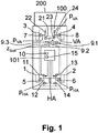
- the Fig. 1 shows a vehicle 200 with a brake system 100 with the components relevant here. Accordingly, to be controlled or second vehicle axle, a rear axle HA with rear wheels 1, 2 and as more or first vehicle axle a front axle VA with front wheels 3, 4 provided.
- the rear wheels 1, 2 can be braked via rear wheel brakes 5, 6 and the front wheels 3, 4 via front wheel brakes 7, 8 by a brake pressure P 1 provided by brake cylinders 9.1 in response to a vehicle target deceleration z set by the driver two-circuit brake valve 9.2 on the rear wheel brakes 5, 6 and the front wheel brakes 7, 8 is transmitted.
- the target vehicle deceleration z setpoint can hereby be detected, for example, by a pressure sensor 9.3 serving as a brake value transmitter, which detects a brake pressure which is controlled by the driver via the brake valve 9.2 Fig. 1 for example, a front axle brake pressure p VA detected.
- the brake system 100 may be an electro-hydraulic or electro-pneumatic brake system, ie, a fluid pressure or an air pressure is controlled.
- the brake system 100 is electrically controlled, in particular, by an EBS control device 101.
- the brake system 100 has an anti-lock braking system (ABS) with an ABS control device 10 which actuates ABS brake valves 11, 12, 13, 14, 21, 22, 23, 24 in pulsed fashion as a function of a detected brake slip.
- ABS controller 10 is integrated into the EBS controller 101 according to this embodiment.
- the ABS brake valves 11, 12, 13, 14 on the rear wheel brakes 5, 6 and the ABS brake valves 21, 22, 23, 24 on the front wheel brakes 7, 8 are each designed as 2/2-way solenoid valves, wherein for each Wheel brake 5, 6, 7, 8, an inlet valve 11, 13, 21, 23 and an outlet valve 12, 14, 22, 24 is provided. If the intake valves 11, 13 are open and the exhaust valves 12, 14 are locked, the rear wheel brakes 5, 6 are acted on by a rear axle brake pressure p HA controlled by the brake valve 9. 2 and thus a corresponding braking by the rear axle HA is effected. Are reversed the intake valves 11, 13 locked and the exhaust valves 12, 14 open, the rear wheel brakes 5, 6 are vented, thus reducing the braking action by the rear axle HA.
- both rear wheel brakes 5, 6 are acted upon by the same rear axle brake pressure p HA , together with the front brake shoes Wheel brakes 7, 8, on each of which the front axle brake pressure p VA acts to achieve a vehicle target deceleration z target corresponding braking effect.
- p HA rear axle brake pressure
- the ABS brake valves 11, 12, 13, 14, 21, 22, 23, 24 of the individual wheel brakes 5, 6, 7, 8 independently of each other, so that at each wheel brake 5, 6, 7 , 8 different brake pressures may be present.
- an electronic control of the vehicle deceleration (vehicle deceleration control) is provided in addition to the ABS control, which regulates the front axle brake pressure p VA and the rear axle brake pressure p HA such that in the vehicle 200 a certain, from the vehicle target deceleration z If dependent vehicle actual deceleration is z actual , ie sets a negative acceleration.
- the rear axle brake pressure p HA is additionally regulated as a function of a detected actual differential slip DS actual .
- the vehicle deceleration control is controlled by an FV controller 15 integrated and configured in the EBS controller 101 according to this embodiment, the ABS brake valves 11, 12, 13, 14 at the rear wheel brakes 5, 6 and the ABS brake valves 21, 22, 23, 24 to the front wheel brakes 7, 8 to control.
- the ABS control device 10 has priority over the FV control device 15 with respect to the control of the ABS brake valves 11, 12, 13, 14, 21, 22, 23, 24. D. h. when an impermissible brake slip is detected on one of the rear wheels 1, 2 or on one of the front wheels 3, 4, an already started vehicle deceleration control is aborted and a conventional ABS control is performed by the ABS control device 10.
- the vehicle deceleration control determines according to this embodiment, as follows, in which vehicle actual deceleration z actual as a function of the vehicle target deceleration z target the ABS brake valves 11, 12, 13, 14, 21, 22, 23, 24 are controlled and the vehicle 200 is delayed by:
- the FV control device 15 stores a maximum deceleration characteristic z Kmax , which is dependent on the desired vehicle deceleration z Soll, and a minimum deceleration characteristic z Kmin , which respectively defines dependencies on a maximum deceleration z max and minimum deceleration z min on the vehicle target represent deceleration z nom.
- the maximum deceleration characteristic z Kmax can also be described as a feeling curve, which runs harmoniously and thus creates a pleasant brake feeling in the driver.
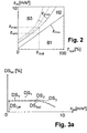
- Fig. 2 is a diagram by way of example the vehicle target deceleration z target as a percentage of the actuation of the brake valve 9.2 against the vehicle-actual deceleration z actual in m / s 2 plotted.
- the maximum delay characteristic z Kmax and the minimum delay characteristic z Kmin divide the diagram into three areas B1, B2, B3.
- a first region B1 lies between the x axis (z setpoint ) and the minimum delay characteristic z Kmin , a second range B2 between minimum delay characteristic z Kmin and maximum delay characteristic z Kmax and a third range B3 above the maximum delay characteristic z Kmax .
- These three areas B1, B2, B3 determine how the FV control device 15, the ABS brake valves 11, 12, 13, 14 on the rear wheel brakes 5, 6 and the ABS brake valves 21, 22, 23, 24 to the front Wheel brake 7, 8 may control and thus which brake force or which rear axle brake pressure p HA or front axle brake pressure p VA as a function of the vehicle target deceleration z Soll and the vehicle-actual deceleration z is on the rear wheel brakes 5, 6 or front wheel brakes 7, 8 is controlled.
- the rear axle brake pressure p HA and the front axle brake pressure p VA are regulated as a function of the three ranges B1, B2, B3 as follows: If a specific brake pressure p HA , p VA is controlled via the brake valve 9.2 to the wheel brakes 5, 6, 7, 8 and the driver requests a desired vehicle deceleration z setpoint and the resulting actual vehicle deceleration z is resulting from the braking of the front and rear wheel brakes 5, 6, 7, 8, in the first region B1, causes the FV control device 15 to open the intake valves 11, 13, 21, 23 and to close the exhaust valves 12, 14, 22, 24 so that both at the rear wheel brakes 5.6 and the front wheel brakes 7, 8, a pressure build-up can take place and thus an increasing deceleration by the rear wheels 1, 2 and the front wheels 3, 4 is made possible.
- the rear axle brake pressure p HA and the front axle brake pressure p VA are thus increased when the actual vehicle deceleration z actual is smaller than the minimum deceleration z min , which is determined by the minimum deceleration z min at a specific preset vehicle deceleration z setpoint.
- characteristic for Kmin for the target vehicle deceleration z target follows. According to Fig. 2 is indicated by way of example that a minimum delay z min and a maximum delay z max follows from the y values of the characteristic curves z Kmin and z Kmax at a specific vehicle nominal deceleration z setpoint (x value).
- This first region B1 is determined by the minimum deceleration characteristic z Kmin , which, for example, can specify a legally stipulated minimum braking as a function of the vehicle nominal deceleration z Soll . Ie. For safety reasons, deceleration is forced below the minimum deceleration characteristic z Kmin - unless the higher-level ABS control intervenes.
- the intake valves 11, 13, 21, 23 and the exhaust valves 12, 14, 22, 24 are driven so that the rear axle brake pressure p HA and the front axle brake pressure p VA are limited ,
- the vehicle 200 can therefore be delayed more strongly only by a further wheel brake of a non-controlled vehicle axle, for example a second rear axle in whose braking behavior the vehicle deceleration control does not intervene.
- the rear axle brake pressure p HA and the front axle brake pressure p VA and thus the braking force of the rear and front wheel brakes 5, 6, 7, 8 are thus dependent on the actual vehicle deceleration z actual to a limited by the maximum delay characteristic z Kmax .
- a pleasant brake feel for the driver can be achieved.
- the actual vehicle deceleration z Ist is additionally regulated as a function of the actual differential slip DS actual , by keeping, reducing or increasing the rear axle brake pressure p HA depending on the actual actual differential slip DS actual ,
- a differential slip control DSR
- differential slip As differential slip is understood according to the embodiment, the difference between a rotational behavior of the front wheels 3, 4 and a rotational behavior of the rear wheels 1, 2.
- the rotational behavior is characterized according to this example by a front axle brake slip DS VA and a rear axle brake slip DS HA , both of which follow from the mean value of the brake shoes of the individual wheels 1, 2, 3, 4 of the respective vehicle axle VA, HA.
- the actual differential slip DS actual is formed from the front axle brake slip DS VA and the rear axle brake slip DS HA as follows: DS is ⁇ DS HA - DS VA / DS HA * 100 ⁇ % ; the difference in the rotational behavior of the vehicle axles VA, HA is thus defined by a deviation of the front axle brake slip DS VA from the rear axle brake slip DS HA , which increases in particular if the rear axle HA is overbrake compared to the front axle VA, ie tends to slip.
- An alternative calculation method of the rotational behavior of the rear wheels 1, 2 relative to the rotational behavior of the front wheels 3, 4 is to determine the actual differential slip DS actual from rotational speeds v VA and v HA of the vehicle axles VA, HA, ie DS is ⁇ v VA - v HA / v VA * 100 ⁇ % .
- the rotational speeds v VA and v HA for example, from an average value of the rotational speeds of the wheels 1, 2, 3, 4 of the respective vehicle axle VA, HA can follow.
- the FV control device 15 After actuation of the brake valve 9.2 and present vehicle target deceleration z target constantly the actual differential slip DS is determined. If the actual brake slip DS Is from a desired brake slip DS target from with a predetermined tolerance value DS T can be involved in non-synchronized ABS brake valves 11, 12, 13, 14, and if the vehicle actual deceleration z is in the second Area B2, the FV control device 15 controls the ABS brake valves 11, 12, 13, 14 of the rear wheels 1, 2 such that the actual differential slip DS is again within the tolerance DS T the desired differential slip DS desired : If the actual differential slip DS is below the desired differential slip DS desired , the rear axle HA is braked relative to the desired differential slip DS desired relative to the front axle VA.
- the intake ABS valves 11, 13 are opened, so that the rear axle brake pressure p HA is increased.
- the rear-axle brake slip DS HA is greater than the front-axle brake slip DS VA relative to the desired differential slip DS Soll , ie the rear axle HA is overbra- ned.
- the rear axle brake pressure p HA is limited, preferably held, so that the braking effect on the rear wheels 1, 2 is not further increased.
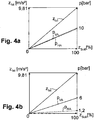
- the target differential slip DS desired which is adjusted to, according to this embodiment depends on the actual vehicle deceleration z Ist , as in Fig. 3a shown.
- the target differential slip DS desired is initially constant and is at a certain offset differential slip DS Off .
- the offset differential slip DS Off is according to this embodiment at the beginning of a braking, ie when no braking forces of the wheel brakes 5, 6, 7, 8 act determined, so that in particular a motor drag torque and wear of the wheels 1, 2, 3, 4th be taken into account.
- the offset differential slip DS Off is positive in a calculation of the actual differential slip DS actual according to the formulas 1.1 or 1.2 when the rear axle HA is the axle driven by the engine of the vehicle 100, since the rear axle HA rotates more slowly by the engine drag torque.
- the target differential slip DS Soll drops in the direction of zero, ie in the direction of a synchronous wheel rotational behavior of the wheels 1, 2, 3, 4 of the first and second vehicle axles HA, VA.
- the rear axle brake pressure p HA is initially limited. According to this embodiment, only a tolerance DS T is provided above the desired differential slip DS Soll . Alternatively or additionally, however, it is also possible for a tolerance DS T to be provided below the desired differential slip DS desired . If the driver requests a higher nominal vehicle deceleration z setpoint by further actuation of the brake valve 9.2, the vehicle 200 is additionally braked only with the front wheel brakes 7, 8 if the actual vehicle deceleration z is not the second range B2 leaves; the actual vehicle deceleration z is rising.
- the actual differential slip DS actual shifts from the point DS 1 to the point DS 2, for example, exactly to the DS desired curve, so that the limitation of the rear axle brake pressure p HA is canceled and the rear axle brake pressure p HA is increased in a pulsed manner.
- the additional braking action of the rear wheel brakes 5, 6 now the braking point DS 2 in the direction of increasing vehicle actual deceleration such shifts in the further course is again in the direction above the target curve to the point DS DS.
- the desired differential slip DS desired drops to smaller values.
- the aim of the procedure is Thus, at high deceleration, to which the front axle VA contributes in the second region B2 without pressure limitation, to make a braking force limitation on the rear axle HA longer and to inhibit a pressure increase. Slipping of the rear axle HA and a consequent intervention of the superordinate ABS control can be avoided and the braking becomes calmer and safer.
- the first vehicle axle is the rear axle HA and the second vehicle axle is the front axle VA
- the actual differential slip DS is according to the formulas 1.1 or 1.2
- the target differential slip DS target as in Fig. 3b shown. Ie. Even then, as the vehicle actual deceleration z actual increases, the setpoint differential slip DS setpoint decreases to smaller values, that is to say in the direction of a synchronous wheel rotational behavior of the rear wheels 1, 2 and the front wheels 3, 4, the front axle being in contrast to the reversed case.
- Brake pressure p VA is limited when the actual differential slip DS Ist is smaller than the target differential slip DS desired and the front axle brake pressure p VA is increased if the actual differential slip DS Ist is greater than the target differential slip DS target .
- the tolerance D T is below the DS target curve.
- the actual differential slip DS Is for example, at the beginning of the differential slip control below the target differential slip DS target and below the tolerance DS T at the point DS 1 in Fig. 3b the front axle brake pressure p VA is initially limited. If a higher nominal vehicle deceleration z desired is requested by the driver by further actuation of the brake valve 9.2, the vehicle 200 is additionally decelerated only with the rear wheel brakes 5, 6 if the actual vehicle deceleration z is not the second range B2 leaves; the actual vehicle deceleration z is rising.
- the actual differential slip DS Ist shifts from the point DS 1 to the point DS 2 above the DS desired curve, so that the limitation of the front-axle brake pressure p VA lifted and the front axle brake pressure p VA is increased.
- the point DS 2 now shifts in the direction of increasing vehicle actual deceleration z Ist in the direction of the braking of the DS target curve to point DS 3 , since the front axle VA is again relatively over-braked by the increased front-axle brake pressure p VA , whereby the actual differential slip DS actual according to the formula 1.1 and 1.2 falls.
- Fig. 3c shifts the falling target difference slip DS target as a function of the vehicle-actual deceleration z actual and the vehicle target deceleration z target to lower or higher vehicle actual delays z actual .
- the desired differential slip DS desired is thus in this case both dependent on the actual vehicle deceleration z actual as well as on the desired vehicle deceleration z Soll .
- the target differential slip DS setpoint does not change until higher values of the actual vehicle deceleration z actual ab are used to the case that the Vehicle actual deceleration z is within a tolerance of, for example, 10% of the vehicle target deceleration z corresponds to target , so that the through the dashed curve DS 1 Soll in Fig. 3c course shown results. If, on the other hand, the vehicle actual deceleration z actual is greater than the vehicle target deceleration z setpoint , the setpoint differential slip DS setpoint falls in accordance with the dashed curve DS 2 setpoint in FIG Fig. 3c already at a lower vehicle actual deceleration z actual .
- the differential slip control is advantageously interrupted in a pulsed manner and the rear axle brake pressure p HA is increased.
- the exhaust valves 12, 14 are opened, so that a pressure reduction the rear wheel brakes 5, 6 takes place in order to quickly reach or fall below the maximum deceleration characteristic z Kmax and to reduce overbraking of the rear axle HA.
- the differential slip control effects an electronic brake force or brake pressure distribution as a function of the axle loads on the front axle VA and the rear axle HA as follows: If the vehicle 200 is unloaded, ie a slight weight force acts on the rear axle HA, the rear wheels 1, 2 are more likely to jam with the same brake application or with a predetermined desired vehicle deceleration z Soll than with a fully loaded vehicle 200 with a higher one Weight on the rear axle HA. This results from the fact that the rear wheels 1, 2 are pressed by the heavy weight in the loaded state stronger on the ground. On the front axle VA, the load has at least no significant influence due to the high engine weight.
- the actual differential slip DS ist thus varies as a function of the load of the vehicle 200 at a specific vehicle target deceleration z setpoint .
- the differential slip control can not directly measure the weight force acting on the rear axle HA, it always controls the ABS valves 11, 12, 13, 14 at the rear wheel brakes 5, 6 at the time when the load-dependent actual differential slip occurs DS Is different from the nominal differential slip DS target by at least the tolerance DS T. Since the FV control device 15 does not regulate the front axle brake pressure p VA in the differential slip control, the differential slip control indirectly achieves a distribution of the braking forces on the vehicle axles VA, HA as a function of the load. Thus, it is possible to deduce a load of the vehicle 200 from the actual differential slip DS actual .
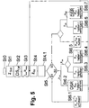
- a front axle brake pressure p VA of 6 bar and a rear axle brake pressure p HA of set only 1.2 bar to one of the vehicle target deceleration z target corresponding actual vehicle-deceleration z is 100% as in Fig. 4a to reach for the fully loaded condition.
- the front axle VA is braked less and the rear axle HA considerably less strongly, whereby early blocking with low loading of front axle VA and in particular rear axle HA can be avoided.
- the maximum deceleration characteristic z Kmax and the minimum deceleration characteristic z Kmin may be stored in the FV controller 15, and at least the maximum deceleration characteristic z Kmax may vary depending on the load.
- the maximum deceleration characteristic z Kmax shifts as in Fig. 2 indicated by dashed lines to higher vehicle actual delays z is out, so that the third area B3 is reduced. Ie. for a specific vehicle target deceleration z desired , the front axle brake pressure p VA is only maintained at a higher vehicle actual deceleration z actual .
- the rear axle brake pressure p HA which is adjusted by the differential slip control according to differential slip criteria to the front axle brake pressure p VA , thereby also increases at a specific vehicle target deceleration z setpoint .
- the vehicle 200 is therefore more delayed in the unloaded state at the same vehicle target deceleration z target than in the loaded state.
- the load state can be communicated to the driver, so that the latter can react accordingly.
- an ECAS system may be provided which electronically controls the air suspension of the vehicle 200 and for this purpose has a displacement sensor, not shown, which measures the path between the rear axle HA and a reference point on the vehicle 200 as a function of the load.
- a mechanical-electronic axle load-dependent brake pressure distribution device (ALB) can also supply the value of the load, which is also controlled by a displacement sensor or a pressure sensor.
- Both systems ie ECAS and ALB, can transmit, for example via the CAN-BUS, the load state detected by these systems to the FV control device 15, which selects the maximum delay characteristic z Kmax in dependence thereon .
- the FV control device 15 determines the loading state itself.
- the loading can be determined on the basis of the measured actual differential slip DS actual as described above, and the loading state can be determined therefrom.
- a further displacement sensor between a vehicle-fixed frame and the vehicle axles HA, VA may be arranged, the load-dependent adjustment can be detected by the FV control device. From the adjustment can be closed to the loading of the vehicle.
- performance data of the engine and vehicle acceleration data can be transmitted from an engine control unit, not shown, via the CAN bus, from which the FV control device 15 can deduce a mass of the vehicle 200 and thus an additional load compared to a dead weight of the vehicle 200. It can also be considered whether a trailer is coupled to the vehicle 200, which may be proportionally involved in the determined mass of the vehicle 200 and the driving behavior on the rear axle HA may additionally influence.
- This information can be transmitted via the CAN-BUS from a trailer control device.
- a behavior be considered a traction control from which also a load condition can be determined.
- the inventive method for electronic brake pressure control can according to Fig. 5 be carried out as follows.
- a step St0 the braking is started, for example by actuation of the brake valve 9.2 by the driver.
- step St1 the vehicle target deceleration z Soll is detected by the brake value transmitter 9.3 as a function of the actuation of the brake valve 9.2, wherein either an actuation path of the brake valve 9.2 or an actuation of the brake valve 9.2 controlled rear axle or front axle brake pressure p HA , p VA is detected.
- an offset differential slip DS Off is set at the beginning of the braking, that is to say when no braking forces still act.
- This offset differential slip DS Off may differ from zero due to an engine drag torque or wear of the wheels 1, 2, 3, 4 and thus varying wheel circumferences.
- a stored maximum deceleration characteristic z Kmax is selected as a function of the load of the vehicle 200. Furthermore, a minimum delay characteristic z Kmin is also defined.
- the characteristic curves z Kmax , z Kmin result in values for the maximum deceleration z max and the minimum deceleration z min , which are used as the basis for the following electronic vehicle deceleration control.
- a fourth step St4 the vehicle actual deceleration z actual is detected. This follows, for example, from an acceleration sensor , not shown, or from the derivation of a determined vehicle reference speed v ref , which can be determined, for example, from an average value of the rotational speeds of the wheels 1, 2, 3, 4. Furthermore, in a step St4.1 determines whether a Einbremsvorgang or a braking operation is present, ie, whether the vehicle-actual deceleration z actual increases or decreases and whether this has requested the driver by increasing or decreasing the vehicle target deceleration z Soll .
- the vehicle actual deceleration z Ist determined in the fourth step St4 by the FV control device 15 as a function of the vehicle target deceleration z Soll is a range B1, B2, B3 of the diagram Fig. 2 assigned or compared, whether the actual vehicle-delay z is greater or less than the maximum delay z max or the minimum delay z min .
- the inlet valves 11, 13, 21, 23 of the rear and front wheel brakes 5, 6, 7 are in a following step St6.1 8, and the exhaust valves 12, 14, 22, 24 are closed so that both the rear axle brake pressure p HA and the front axle brake pressure p VA are increased.
- the intake valves 11, 13 of the rear wheel brakes 5, 6 are dependent the actual differential slip DS is , which is preferably determined during the entire braking of the FV control device 15, driven such that this within the tolerance DS T corresponds to the stored in the FV control device 15 target differential slip DS target , the at least Beginning of the braking is equal to the set in the second step St2 offset differential slip DS Off and can change during braking vehicle-dependent dependent.
- the rear axle brake pressure p HA can either be maintained or increased.
- can also in the second Range B2 be provided a pressure lowering by the differential slip control by the exhaust valves 12, 14 of the rear wheel brakes 5, 6 are driven.
- the intake valves 21, 23 and the exhaust valves 22, 24 of the front wheel brakes 7, 8 are preferably controlled in the second and in the third area B2, B3 depending on whether a braking or braking operation has been detected in step St4.1, the front axle -Bremstik p VA is held or increased at a Einbremsvorgang in the second region B2 in a step St6.3 and B3 in the third area according to a step St6.5 is held and limited in a braking operation in the second and third areas B2, B3, ie held or is decreased (steps St6.4 and St6.6), depending on whether the vehicle target deceleration z target has already been reached or not.
- the intake valves 11, 13 and the exhaust valves 12, 14 of the rear wheel brakes 5, 6 are also controlled in the third area B3, depending on whether there is a Einbremsvorgang or a Ausbremsvorgang, the rear axle brake pressure p HA at a Einbremsvorgang according to step St6. 5 and limited in a Ausbremsvorgang step St6.7, ie held or reduced, depending on whether the target differential slip DS target is already reached or not, the rear axle brake pressure p HA at an actual differential slip DS actual greater as the target differential slip DS target , ie at a relative overbraking, is reduced.
- the electronic vehicle deceleration control begins again within a braking with the fourth step St4.
- the detected actual vehicle deceleration z actual is always a range B1, B2, B3 assigned and the rear axle brake pressure p HA and the front axle brake pressure p VA set accordingly.
- step St6.2 proceeds according to Fig. 6 as follows: In a step St100, the actual differential slip DS Ist is compared with the target differential slip DS Soll , which in the FV control device 15 as in Fig. 3 is shown stored and in which the determined in step St2 of the vehicle deceleration control offset differential slip DS Off is taken into account.
- the FV control device 15 causes a limiting of the rear axle brake pressure p HA in a step St101.1, so that the braking force of the wheel brakes 5, 6 on the rear axle HA does not is further increased. If the actual differential slip DS ist is smaller than the desired differential slip DS desired or smaller than the tolerance DS T , then an increase of the rear axle brake pressure p HA is requested by the FV control device 15 in a step St101.2 HA is braked relative to the front axle VA. If the actual differential slip DS is within the tolerance DS T equal to the desired differential slip DS desired , the procedure starts again from the beginning; the locking tendency of the rear axle HA was adapted to the locking tendency of the front axle VA.
- FIGS. 7a and 7b show by way of example a maximum deceleration characteristic z Kmax with an upper tolerance z u T and a lower tolerance z l T during a braking process ( Fig. 7a ) and a braking process ( Fig. 7b ).
- the start is at point P1, which corresponds to a braking situation in which the driver specifies a desired vehicle deceleration z setpoint .
- the maximum deceleration characteristic z Kmax is reached, ie of the invention Vehicle deceleration control, both the rear axle brake pressure p HA and the front axle brake pressure p VA by limiting the intake valves 11, 13, 21, 23 and the exhaust valves 12, 14, 22, 24 limited, preferably held, regardless of the detected actual differential slip DS Is the vehicle lst deceleration z Ist lies in the third area B3.
- the vehicle actual deceleration z is located in the second region B2. Since it is a Einbremsvorgang, the front-axle brake pressure p VA is either held or increased in this second area B2, depending on whether the vehicle target deceleration z Soll has already been achieved.
- the rear axle brake pressure p HA is regulated as a function of the detected actual differential slip DS actual .
- the rear axle HA is over-braked relative to the front axle VA, so that the rear axle brake pressure p HA is maintained and the front axle brake pressure p VA is increased. If the actual differential slip DS is below the desired differential slip DS desired , the rear axle HA is braked and an increase in the rear axle brake pressure p HA is requested. If, on reaching the point P2, the actual differential slip DS actual is already lower than the desired differential slip DS desired , both the rear axle brake pressure p HA and the front axle brake pressure p VA are increased.
- the vehicle 200 is delayed such that the point P3 is reached, which is on the maximum deceleration characteristic z Kmax , so that both the rear axle brake pressure p HA and the front axle brake pressure p VA are limited again.
- point P4 is reached at which the procedure is repeated as at point P2.
- the braking situation shifts accordingly Fig. 7b to point P6, which is above the upper tolerance z u T , ie an increase of the front axle brake pressure p VA and the rear axle brake pressure p HA is not allowed. If the detected actual differential slip at this point P6 DS is smaller than the setpoint differential slip DS desired , the rear axle brake pressure p HA is initially maintained and the front axle brake pressure p VA is maintained according to the vehicle target deceleration z setpoint specified by the driver lowered to compensate for the under-braking of the rear axle HA relative to the front axle VA.
- both the front-axle brake pressure p VA and the rear-axle brake pressure p HA are lowered in order to comply with the driver's request until the actual differential slip DS is within the tolerance D T again corresponds to the desired differential slip DS desired .
- the braking situation shifts from point P6 to point P7, at which point the measures described above are repeated to reach point P8 if the driver continues to release the brake pedal, ie actively reduces the vehicle target deceleration z target itself.
- a longer actuation time of the exhaust valves 12, 14, 22, 24 can be selected once for pressure reduction, and a longer actuation time of the intake valves 11, 13, 21 can be selected once during a change from a braking process to a braking process for increasing the pressure , 23, to overcome a hysteresis behavior in reversing the braking effects of a brake.
Landscapes
- Engineering & Computer Science (AREA)
- Transportation (AREA)
- Mechanical Engineering (AREA)
- Regulating Braking Force (AREA)
Claims (18)
- Procédé de régulation d'une décélération de véhicule en fonction d'une différence de patinage entre deux essieux de véhicules (HA, VA) dans un véhicule (200) doté d'un système de freins ABS (100), avec au moins les étapes suivantes :saisie d'une décélération de consigne du véhicule (zSoll) définie par le conducteur (St1) et/ou saisie d'une décélération réelle du véhicule (zIst) (St1, St4), etrégulation d'une pression de freinage (pHA, pVA) sur les freins de roues (5, 6, 7, 8) d'un essieu de véhicule (HA, VA) à réguler par commande de soupapes de freins ABS (11, 12, 13, 14, 21, 22, 23, 24) de telle sorte que la pression de freinage (pHA, pVA) sur les freins de roues (5, 6, 7, 8) de l'essieu de véhicule (HA, VA) à réguler est régulée (St6.2) en fonction d'une différence de patinage réelle (DSIst) saisie, de sorte que la différence de patinage réelle (DSIst) correspond à une différence de patinage de consigne (DSSoll),dans lequel la différence de patinage réelle (DSIst) fournit la différence dans un comportement de rotation de l'essieu de véhicule (HA, VA) à réguler par rapport à un autre essieu de véhicule (VA, HA), etdans lequel la différence de patinage de consigne (DSSoll) dépend de la décélération réelle du véhicule (zIst) saisie et/ou de la décélération de consigne du véhicule saisie (zSoll),dans lequel la pression de freinage (pHA, pVA) sur les freins de roues (5, 6, 7, 8) de l'essieu de véhicule (HA, VA) à réguler est limitée lorsqu'il y a surfreinage sur l'essieu de véhicule (HA, VA) à réguler relativement à l'autre essieu de véhicule (VA, HA) (St101.1),caractérisé en ce quela différence de patinage de consigne (DSSoll) décroît lors d'une augmentation de la décélération de consigne du véhicule (zSoll) et/ou de la décélération réelle du véhicule (zIst) vers un comportement de rotation synchrone des roues (1, 2, 3, 4) de l'essieu de véhicule (HA, VA) à réguler et des roues (3, 4, 1,2) de l'autre essieu de véhicule (VA, HA), de sorte que la pression de freinage (pHA, pVA) sur l'essieu de véhicule (VA, HA) à réguler est déjà limitée lors d'un surfreinage relatif réduit de l'essieu de véhicule (HA, VA) à réguler.
- Procédé selon la revendication 1, caractérisé en ce que la pression de freinage (pHA, pVA) sur les freins de roues (5, 6, 7, 8) de l'essieu de véhicule (HA, VA) à réguler est augmentée, lorsqu'il y a sous-freinage sur l'essieu de véhicule (HA, VA) à réguler relativement à l'autre essieu de véhicule (VA, HA).
- Procédé selon la revendication 1 ou 2, caractérisé en ce que la différence de patinage réelle (DSIst) est calculée à partir d'une différence d'un glissement de freinage d'essieu arrière (DSHA) mesuré moins un glissement de freinage d'essieu avant (DSVA) mesuré, de préférence normée sur le glissement de freinage d'essieu arrière (DSHA), ou une différence d'une vitesse d'axe d'essieu avant (vVA) mesurée moins une vitesse d'axe d'essieu arrière (vHA) mesurée, de préférence normée sur la vitesse d'axe d'essieu avant (vVA), dans lequel l'essieu arrière (HA) est l'essieu de véhicule entraîné par un moteur.
- Procédé selon l'une des revendications ci-dessus, caractérisé en ce que, si l'essieu à réguler est l'essieu arrière (HA), la pression de freinage (pHA, pVA) sur les freins de roues arrière (5, 6)- est limitée, lorsque la différence de patinage réelle (DSIst) est supérieure à la différence de patinage de consigne (DSSoll), et- est accrue, lorsque la différence de patinage réelle (DSIst) est inférieure à la différence de patinage de consigne (DSSoll), et
si l'essieu de véhicule à réguler est l'essieu avant (VA), la pression de freinage (pHA, pVA) sur les freins de roues avant (5, 6)- est limitée, lorsque la différence de patinage réelle (DSIst) est inférieure à la différence de patinage de consigne (DSSoll), et- est accrue, lorsque la différence de patinage réelle (DSIst) est supérieure à la différence de patinage de consigne (DSSoll). - Procédé selon l'une des revendications ci-dessus, caractérisé en ce que la pression de freinage (pHA, pVA) sur les freins de roues (5, 6, 7, 8) de l'essieu de véhicule (HA, VA) à réguler est régulée en fonction d'une différence de patinage réelle (DSIst) saisie (St6.2), de sorte que la différence de patinage réelle (DSIst) correspond à une différence de patinage de consigne (DSSoll) à l'intérieur d'une tolérance (DST), dans lequel la tolérance (DST) se trouve au-dessus et/ou en dessous de la différence de patinage de consigne (DSSoll).
- Procédé selon l'une des revendications ci-dessus, caractérisé en ce qu'il est en outre prévu,
de spécifier (St3) une décélération maximale (zmax) ainsi qu'une décélération minimale (zmin) respectives en fonction de la décélération de consigne du véhicule (zSoll), et
de réguler la pression de freinage (pHA, pVA) sur les freins de roues (5, 6, 7, 8) d'un premier et d'un deuxième essieu de véhicule (HA, VA) en fonction de la décélération réelle du véhicule saisie (zIst) par commande de soupapes de freins ABS (11, 12, 13, 14, 21, 22, 23, 24) de telle sorte que- la pression de freinage (pHA, pVA) sur les freins de roues (5, 6, 7, 8) du premier et du deuxième essieu de véhicule (HA, VA) est augmentée lorsque la décélération réelle du véhicule (zIst) est inférieure à la décélération minimale (zmin) afin d'atteindre un effet de freinage minimal (St6.1), et- la pression de freinage (pHA, pVA) sur les freins de roues (5, 6, 7, 8) du premier et du deuxième essieu de véhicule (HA, VA) est limitée lorsque la décélération réelle du véhicule (zIst) est supérieure à la décélération maximale (zmax) afin de limiter l'effet de freinage du premier essieu de véhicule (HA, VA) (St6.5, St6.6, St6.7), et- la pression de freinage (pHA, pVA) sur les freins de roues (5, 6, 7, 8) du deuxième essieu de véhicule (HA, VA) est régulée en fonction de la différence de patinage réelle saisie (DSIst), lorsque la décélération réelle du véhicule (zIst) est inférieure à la décélération maximale (zmax) et supérieure à la décélération minimale (zmin), de sorte que la différence de patinage réelle (DSIst) correspond à la différence de patinage de consigne (DSSoll) (St6.2),dans lequel le premier essieu de véhicule (HA, VA) est l'essieu de véhicule supplémentaire et le deuxième essieu de véhicule (HA, VA) est l'essieu de véhicule (HA, VA) à réguler. - Procédé selon la revendication 6, caractérisé en ce que la décélération maximale (zmax) est spécifiée à l'aide d'une caractéristique de décélération maximale (zKmax) et la décélération minimale (zmin) est spécifiée à l'aide d'une caractéristique de décélération minimale (zKmin), qui représentent respectivement une dépendance de la décélération maximale (zmax) et de la décélération minimale (zmin) par rapport à la décélération de consigne du véhicule (zSoll).
- Procédé selon la revendication 7, caractérisé en ce que la caractéristique de décélération maximale (zKmax) dépend du chargement du véhicule (200), dans lequel la caractéristique de décélération maximale (zKmax) augmente plus fortement lorsque le chargement est réduit, de sorte que la pression de freinage (pHA, pVA) en cas de chargement réduit du véhicule (200) et lors d'une décélération réelle du véhicule saisie (zIst) est limitée contrairement à un chargement élevé du véhicule (200) .
- Procédé selon la revendication 8, caractérisé en ce que le chargement du véhicule (200) est mesuré avec un capteur de charge à l'essieu ou déduit de la différence de patinage réelle saisie (DSIst).
- Procédé selon l'une des revendications 6 à 9, caractérisé en ce que la caractéristique de décélération maximale (zKmax) comporte une courbe harmonique sans gradations pour limiter la pression de freinage (pHA, pVA) sans ralentir brusquement le véhicule (200) .
- Procédé selon l'une des revendications 6 à 10, caractérisé en ce que la pression de freinage (pHA, pVA) sur les freins de roues (5, 6, 7, 8) du premier essieu de véhicule (HA, VA)- est maintenue ou augmentée lors d'une opération de rodage, et- est maintenue ou réduite lors d'une opération de freinage,lorsque la décélération réelle du véhicule (zIst) est inférieure à la décélération maximale (zmax) et supérieure à la décélération minimale (zmin).
- Procédé selon l'une des revendications 6 à 11, caractérisé en ce que la pression de freinage (pHA, pVA) sur les freins de roues (5, 6, 7, 8) du premier essieu de véhicule (HA, VA) est réduite en fonction de la différence de patinage réelle (DSIst), lorsque la décélération réelle du véhicule (zIst) est supérieure à la décélération maximale (zmax) et le deuxième essieu de véhicule (HA, VA) est en surfreinage relativement au premier essieu de véhicule (VA, HA) (St6.5, St6.6, St6.7).
- Procédé selon l'une des revendications ci-dessus, caractérisé en ce que l'essieu de véhicule à réguler est un essieu arrière (HA) du véhicule (200) ou un essieu avant (VA) du véhicule (200), et l'essieu de véhicule supplémentaire est un essieu avant (VA) du véhicule (200) lorsque l'essieu de véhicule à réguler est un essieu arrière (HA) du véhicule (200), ou est un essieu arrière (HA) du véhicule (200) lorsque l'essieu de véhicule à réguler est un essieu avant (VA) du véhicule (200).
- Procédé selon l'une des revendications ci-dessus, caractérisé en ce que lors d'une limitation de la pression de freinage (pHA, pVA) sur les freins de roues (5, 6, 7, 8) de l'essieu de véhicule à réguler ou de l'essieu de véhicule supplémentaire (HA, VA), la pression de freinage (pHA, pVA) est seulement maintenue ou réduite et n'est pas augmentée.
- Procédé selon l'une des revendications ci-dessus, caractérisé en ce que dans le cas où la différence de patinage de consigne (DSSoll) est fonction de la décélération réelle du véhicule (zIst) et de la décélération de consigne du véhicule (zSoll), la différence de patinage de consigne (DSSoll, DS1 Soll, DS2 Soll)- décroît aussi tôt que la décélération réelle du véhicule (zIst) diminue, dans le cas où la décélération réelle du véhicule (zIst) est supérieure à la décélération de consigne du véhicule (zSoll), et- décroît lorsque la décélération réelle du véhicule (zIst) augmente, dans le cas où la décélération réelle du véhicule (zIst) est inférieure à la décélération de consigne du véhicule (zSoll),contrairement au cas où la décélération réelle du véhicule (zIst) correspond à la décélération de consigne du véhicule (zSoll) à l'intérieur d'une tolérance.
- Dispositif (15) de régulation électronique d'une décélération de véhicule dans un véhicule (200) doté d'un système de freins ABS (100),
destiné à mettre en oeuvre un procédé selon l'une des revendications ci-dessus, dans lequel le dispositif (15) est conçu
pour saisir une décélération de consigne du véhicule (zSoll) définie par le conducteur) et/ou une décélération réelle du véhicule (zIst), et
pour commander des soupapes de freins ABS (11, 12, 13, 14, 21, 22, 23, 24) sur des freins de roues (5, 6, 7, 8) d'un essieu de véhicule (HA, VA) à réguler en fonction de la différence de patinage réelle saisie (DSIst) de telle sorte que la différence de patinage réelle (DSIst) correspond à une différence de patinage de consigne (DSSoll),
dans lequel la différence de patinage réelle (DSIst) fournit la différence dans un comportement de rotation de l'essieu de véhicule (HA, VA) à réguler par rapport à un autre essieu de véhicule (VA, HA), et
dans lequel la différence de patinage de consigne (DSSoll) dépend de la décélération réelle du véhicule (zIst) saisie et/ou de la décélération de consigne du véhicule saisie (zSoll). - Dispositif selon la revendication 16, caractérisé en ce que le deuxième essieu de véhicule est un essieu arrière (HA) et le premier essieu de véhicule (HA, VA) est un essieu avant (VA) du véhicule (200).
- Véhicule (200) doté d'un système de freinage (100) comportant au moins :une soupape de freinage (9.2) commandant une pression de freinage (pHA, pVA) sur des freins de roues (5, 6, 7, 8) du véhicule (200),un transducteur de puissance de freinage (9.3) saisissant une décélération de consigne du véhicule (zSoll).des moyens de saisie d'une décélération réelle du véhicule (zIst),des soupapes de freins ABS (11, 12, 13, 14, 21, 22, 23, 24), ainsiqu'un dispositif (15) selon l'une des revendications 16 ou 17, en particulier destiné à mettre en oeuvre un procédé selon l'une des revendications 1 à 15.
Applications Claiming Priority (2)
| Application Number | Priority Date | Filing Date | Title |
|---|---|---|---|
| DE102015006703.6A DE102015006703A1 (de) | 2015-05-23 | 2015-05-23 | Verfahren und Vorrichtung zum elektronischen Regeln einer Fahrzeugverzögerung in Abhängigkeit eines Differenzschlupfes zwischen zwei Fahrzeugachsen |
| PCT/EP2016/000668 WO2016188603A1 (fr) | 2015-05-23 | 2016-04-26 | Procédé et dispositif de régulation électronique d'un système de ralentissement de véhicule en fonction d'une différence de glissement entre deux essieux de véhicule |
Publications (2)
| Publication Number | Publication Date |
|---|---|
| EP3303074A1 EP3303074A1 (fr) | 2018-04-11 |
| EP3303074B1 true EP3303074B1 (fr) | 2019-04-10 |
Family
ID=55860782
Family Applications (1)
| Application Number | Title | Priority Date | Filing Date |
|---|---|---|---|
| EP16719211.1A Active EP3303074B1 (fr) | 2015-05-23 | 2016-04-26 | Procédé et dispositif de régulation électronique d'un système de ralentissement de véhicule en fonction d'une différence de glissement entre deux essieux de véhicule |
Country Status (5)
| Country | Link |
|---|---|
| US (1) | US10538227B2 (fr) |
| EP (1) | EP3303074B1 (fr) |
| CN (1) | CN107531220A (fr) |
| DE (1) | DE102015006703A1 (fr) |
| WO (1) | WO2016188603A1 (fr) |
Families Citing this family (7)
| Publication number | Priority date | Publication date | Assignee | Title |
|---|---|---|---|---|
| DE102017003782A1 (de) | 2017-04-20 | 2018-10-25 | Wabco Gmbh | Verfahren zum Überwachen einer Umsetzung einer automatisiert angeforderten Bremsvorgabe sowie Bremssystem |
| CN109080608B (zh) * | 2018-06-04 | 2021-01-26 | 东南大学 | 一种无人驾驶车辆在雨雪湿滑路面紧急制动时的制动力控制方法 |
| JP7310169B2 (ja) * | 2019-02-25 | 2023-07-19 | 株式会社アドヴィックス | 車両の制動制御装置 |
| CN110371129B (zh) * | 2019-06-28 | 2020-09-11 | 湖南行必达网联科技有限公司 | 主车和挂车制动一致性判断方法、装置及制动系统 |
| DE102019133373A1 (de) * | 2019-12-06 | 2021-06-10 | Zf Cv Systems Global Gmbh | Verfahren zur Verzögerungsregelung eines Fahrzeuges sowie Bremssystem hierfür |
| CN113525313B (zh) * | 2021-09-17 | 2021-12-31 | 天津所托瑞安汽车科技有限公司 | 制动力分配方法、设备和存储介质 |
| US12054045B1 (en) * | 2023-10-19 | 2024-08-06 | Ford Global Technologies, Llc | Traction control for all-wheel drive vehicles |
Family Cites Families (29)
| Publication number | Priority date | Publication date | Assignee | Title |
|---|---|---|---|---|
| US7164117B2 (en) * | 1992-05-05 | 2007-01-16 | Automotive Technologies International, Inc. | Vehicular restraint system control system and method using multiple optical imagers |
| US20050192727A1 (en) * | 1994-05-09 | 2005-09-01 | Automotive Technologies International Inc. | Sensor Assemblies |
| DE10081536D2 (de) * | 1999-06-08 | 2002-08-14 | Luk Lamellen & Kupplungsbau | Verfahren zur Abbildung der Geschwindigkeit eines Rades bei Kraftfahrzeugen |
| CA2276643A1 (fr) * | 1999-06-23 | 2000-12-23 | Bombardier Inc. | Vehicule tout terrain a enfourcher avec differentiel progressif |
| US6528959B2 (en) * | 2000-07-19 | 2003-03-04 | Honda Giken Kogyo Kabushiki Kaisha | Driving force control system for front-and-rear wheel drive vehicles |
| DE10137148A1 (de) | 2001-07-30 | 2003-02-13 | Knorr Bremse Systeme | Bremsanlage für Nutzfahrzeuganhänger |
| US6487486B1 (en) * | 2001-08-14 | 2002-11-26 | Daimlerchrysler Corporation | Automatic differential control logic |
| JP2004051023A (ja) * | 2002-07-22 | 2004-02-19 | Toyota Motor Corp | 車両の制御装置 |
| JP4099096B2 (ja) * | 2003-04-07 | 2008-06-11 | トヨタ自動車株式会社 | 車輌の制動制御装置 |
| JP2004328991A (ja) * | 2003-04-09 | 2004-11-18 | Nissan Motor Co Ltd | 車両の左右輪駆動装置 |
| SE527735C2 (sv) * | 2004-10-11 | 2006-05-23 | Jonas Alfredson | Differentialspärr |
| JP4353058B2 (ja) * | 2004-10-12 | 2009-10-28 | トヨタ自動車株式会社 | 電動式パワーステアリング装置用制御装置 |
| US7935015B2 (en) * | 2005-05-30 | 2011-05-03 | Toyota Jidosha Kabushiki Kaisha | Control device for vehicle drive apparatus |
| JP4238845B2 (ja) * | 2005-06-22 | 2009-03-18 | トヨタ自動車株式会社 | 車両用駆動装置の制御装置 |
| US8565993B2 (en) * | 2005-10-11 | 2013-10-22 | Volvo Car Corporation | Enhanced yaw stability control to mitigate a vehicle's abnormal yaw motion due to a disturbance force applied to vehicle body |
| DE102006045317A1 (de) | 2005-11-08 | 2007-05-24 | Continental Teves Ag & Co. Ohg | Verfahren zur elektronischen Bremskraftverteilung |
| US7641014B2 (en) * | 2006-01-31 | 2010-01-05 | Robert Bosch Gmbh | Traction control system and method |
| DE102006005468B4 (de) * | 2006-02-07 | 2017-09-21 | Zf Friedrichshafen Ag | Verfahren zum Betreiben eines Parallelhybridantriebsstranges eines Fahrzeuges |
| DE102006032064A1 (de) * | 2006-07-11 | 2008-01-24 | Knorr-Bremse Systeme für Nutzfahrzeuge GmbH | Elektronisches Bremssystem ohne Drucksensoren in Radmodulen und Verfahren zur Bremsdrucksteuerung |
| US8108104B2 (en) * | 2006-11-16 | 2012-01-31 | Ford Global Technologies, Llc | Tripped rollover mitigation and prevention systems and methods |
| DE102008009948B3 (de) | 2008-02-20 | 2009-10-01 | Knorr-Bremse Systeme für Nutzfahrzeuge GmbH | Bremsanlage für Nutzfahrzeuge |
| DE102009021685B4 (de) * | 2009-05-18 | 2024-01-11 | Zf Cv Systems Hannover Gmbh | Bremssystem mit Dauerbremsintegration |
| GB2480852A (en) * | 2010-06-03 | 2011-12-07 | Mira Ltd | Yaw motion control of a vehicle |
| JP5857593B2 (ja) * | 2011-09-29 | 2016-02-10 | トヨタ自動車株式会社 | 車両の制動制御装置 |
| US9127765B2 (en) * | 2011-10-12 | 2015-09-08 | Toyota Jidosha Kabushiki Kaisha | Vehicle drive apparatus control apparatus |
| DE102011118130B4 (de) * | 2011-11-10 | 2013-08-01 | Knorr-Bremse Systeme für Nutzfahrzeuge GmbH | Verfahren und Vorrichtung zur elektronischen Regelung der Bremskraftverteilung in Abhängigkeit zum Differenzschlupf |
| US10518765B2 (en) * | 2012-01-11 | 2019-12-31 | Ford Global Technologies, Llc | Electronic stability control system for electric drive vehicle |
| DE102013207127A1 (de) * | 2012-06-12 | 2013-12-12 | Ford Global Technologies, Llc | Verfahren zum Anpassen eines Bremsvorgangs |
| US9327725B2 (en) * | 2013-05-28 | 2016-05-03 | Eric N. Anderfaas | Geometry for improved driveline-suspension coupling of narrow leaning commuter vehicles |
-
2015
- 2015-05-23 DE DE102015006703.6A patent/DE102015006703A1/de not_active Withdrawn
-
2016
- 2016-04-26 CN CN201680024228.1A patent/CN107531220A/zh active Pending
- 2016-04-26 US US15/559,062 patent/US10538227B2/en active Active
- 2016-04-26 EP EP16719211.1A patent/EP3303074B1/fr active Active
- 2016-04-26 WO PCT/EP2016/000668 patent/WO2016188603A1/fr active Application Filing
Non-Patent Citations (1)
| Title |
|---|
| None * |
Also Published As
| Publication number | Publication date |
|---|---|
| DE102015006703A1 (de) | 2016-11-24 |
| WO2016188603A1 (fr) | 2016-12-01 |
| CN107531220A (zh) | 2018-01-02 |
| US10538227B2 (en) | 2020-01-21 |
| US20180072287A1 (en) | 2018-03-15 |
| EP3303074A1 (fr) | 2018-04-11 |
Similar Documents
| Publication | Publication Date | Title |
|---|---|---|
| EP3303074B1 (fr) | Procédé et dispositif de régulation électronique d'un système de ralentissement de véhicule en fonction d'une différence de glissement entre deux essieux de véhicule | |
| EP3386814B1 (fr) | Procédé de réglage de pressions de freinage d'un véhicule et système de freinage pour la mise en oeuvre dudit procédé | |
| EP3303075B1 (fr) | Procédé et dispositif de régulation électronique d'un système de ralentissement de véhicule dans un système de freinage abs | |
| EP3303076B1 (fr) | Procédé et dispositif de régulation électronique d'un système de ralentissement de véhicule dans un système de freinage abs | |
| EP1919728B1 (fr) | Systeme de controle d'adherence en descente pour un vehicule a moteur | |
| EP1016572B1 (fr) | Dispositif et procédé de stabilisation d'un attelage de véhicules constitué d'un tracteur et d'une remorque | |
| EP2040962B1 (fr) | Procédé pour compenser la décélération de freinage lors d'une régulation d'un véhicule | |
| EP3322619B1 (fr) | Procédé et dispositif de régulation électronique d'un ralentissement d'un véhicule à régulation du glissement de freinage | |
| DE102005013741A1 (de) | Steuervorrichtung zum Automatischen Abbremsen für ein Fahrzeug | |
| DE102012222490B4 (de) | Verfahren zur Erhöhung der Fahrstabilität eines Fahrzeugs | |
| DE19703688B4 (de) | Verfahren und Vorrichtung zur Steuerung einer Bremsanlage | |
| WO2003002392A1 (fr) | Procede permettant de modifier le systeme de regulation de la stabilite directionnelle d'un vehicule | |
| EP0715999B1 (fr) | Procédé pour contrÔler le ralentisseur d'un véhicule | |
| DE102018001695A1 (de) | Verfahren zur Bremssteuerung eines Fahrzeugzuges sowie derart betreibbarer Fahrzeugzug | |
| EP1131235B1 (fr) | Procede et dispositif de stabilisation d'un vehicule equipe d'un systeme de freinage a controle de glissement | |
| DE102015015922A1 (de) | Verfahren zum Einstellen von Bremsdrücken an pneumatisch betätigten Radbremsen eines Fahrzeugs, Bremsanlage zur Durchführung des Verfahrens sowie Fahrzeug | |
| DE60034422T2 (de) | Erhöhung der Fahrzeugsteuerbarkeit und Fahrstabilität beim Bremsen in einer Kurve | |
| EP1027242B1 (fr) | Procede pour reguler les caracteristiques de pression de freinage dans les freins de roues arriere d'un systeme de freinage de vehicule a regulation electronique de la repartition de la pression de freinage | |
| DE102011017018B3 (de) | Verfahren zur Lastabhängigen Bremsdruckregelung | |
| DE102007056884A1 (de) | Verfahren zur Ansteuerung einer Kupplung | |
| EP1912838B1 (fr) | Procede de commande de freins continus d'un vehicule a moteur | |
| EP1156952B1 (fr) | Dispositif et procede de regulation du glissement de roues apres detection d'un derapage | |
| DE102010039823A1 (de) | Verfahren und Vorrichtung zur Antriebsschlupfregelung eines Einspurfahrzeugs | |
| DE10248079A1 (de) | Verfahren und Vorrichtung zur Bremskraftverteilung auf die Achsen eines Kraftfahrzeuges | |
| EP1514755B1 (fr) | Procédé de commande de la pression d'entrée d'une valve de commande d'un système de freinage à anti-blocage |
Legal Events
| Date | Code | Title | Description |
|---|---|---|---|
| STAA | Information on the status of an ep patent application or granted ep patent |
Free format text: STATUS: THE INTERNATIONAL PUBLICATION HAS BEEN MADE |
|
| PUAI | Public reference made under article 153(3) epc to a published international application that has entered the european phase |
Free format text: ORIGINAL CODE: 0009012 |
|
| STAA | Information on the status of an ep patent application or granted ep patent |
Free format text: STATUS: REQUEST FOR EXAMINATION WAS MADE |
|
| 17P | Request for examination filed |
Effective date: 20180102 |
|
| AK | Designated contracting states |
Kind code of ref document: A1 Designated state(s): AL AT BE BG CH CY CZ DE DK EE ES FI FR GB GR HR HU IE IS IT LI LT LU LV MC MK MT NL NO PL PT RO RS SE SI SK SM TR |
|
| AX | Request for extension of the european patent |
Extension state: BA ME |
|
| DAV | Request for validation of the european patent (deleted) | ||
| DAX | Request for extension of the european patent (deleted) | ||
| GRAP | Despatch of communication of intention to grant a patent |
Free format text: ORIGINAL CODE: EPIDOSNIGR1 |
|
| STAA | Information on the status of an ep patent application or granted ep patent |
Free format text: STATUS: GRANT OF PATENT IS INTENDED |
|
| INTG | Intention to grant announced |
Effective date: 20190130 |
|
| GRAS | Grant fee paid |
Free format text: ORIGINAL CODE: EPIDOSNIGR3 |
|
| GRAA | (expected) grant |
Free format text: ORIGINAL CODE: 0009210 |
|
| STAA | Information on the status of an ep patent application or granted ep patent |
Free format text: STATUS: THE PATENT HAS BEEN GRANTED |
|
| AK | Designated contracting states |
Kind code of ref document: B1 Designated state(s): AL AT BE BG CH CY CZ DE DK EE ES FI FR GB GR HR HU IE IS IT LI LT LU LV MC MK MT NL NO PL PT RO RS SE SI SK SM TR |
|
| REG | Reference to a national code |
Ref country code: GB Ref legal event code: FG4D Free format text: NOT ENGLISH |
|
| REG | Reference to a national code |
Ref country code: CH Ref legal event code: EP Ref country code: AT Ref legal event code: REF Ref document number: 1118247 Country of ref document: AT Kind code of ref document: T Effective date: 20190415 |
|
| REG | Reference to a national code |
Ref country code: IE Ref legal event code: FG4D Free format text: LANGUAGE OF EP DOCUMENT: GERMAN |
|
| REG | Reference to a national code |
Ref country code: DE Ref legal event code: R096 Ref document number: 502016004145 Country of ref document: DE |
|
| REG | Reference to a national code |
Ref country code: SE Ref legal event code: TRGR |
|
| REG | Reference to a national code |
Ref country code: NL Ref legal event code: FP |
|
| REG | Reference to a national code |
Ref country code: LT Ref legal event code: MG4D |
|
| PG25 | Lapsed in a contracting state [announced via postgrant information from national office to epo] |
Ref country code: AL Free format text: LAPSE BECAUSE OF FAILURE TO SUBMIT A TRANSLATION OF THE DESCRIPTION OR TO PAY THE FEE WITHIN THE PRESCRIBED TIME-LIMIT Effective date: 20190410 Ref country code: ES Free format text: LAPSE BECAUSE OF FAILURE TO SUBMIT A TRANSLATION OF THE DESCRIPTION OR TO PAY THE FEE WITHIN THE PRESCRIBED TIME-LIMIT Effective date: 20190410 Ref country code: HR Free format text: LAPSE BECAUSE OF FAILURE TO SUBMIT A TRANSLATION OF THE DESCRIPTION OR TO PAY THE FEE WITHIN THE PRESCRIBED TIME-LIMIT Effective date: 20190410 Ref country code: LT Free format text: LAPSE BECAUSE OF FAILURE TO SUBMIT A TRANSLATION OF THE DESCRIPTION OR TO PAY THE FEE WITHIN THE PRESCRIBED TIME-LIMIT Effective date: 20190410 Ref country code: FI Free format text: LAPSE BECAUSE OF FAILURE TO SUBMIT A TRANSLATION OF THE DESCRIPTION OR TO PAY THE FEE WITHIN THE PRESCRIBED TIME-LIMIT Effective date: 20190410 Ref country code: PT Free format text: LAPSE BECAUSE OF FAILURE TO SUBMIT A TRANSLATION OF THE DESCRIPTION OR TO PAY THE FEE WITHIN THE PRESCRIBED TIME-LIMIT Effective date: 20190910 Ref country code: NO Free format text: LAPSE BECAUSE OF FAILURE TO SUBMIT A TRANSLATION OF THE DESCRIPTION OR TO PAY THE FEE WITHIN THE PRESCRIBED TIME-LIMIT Effective date: 20190710 |
|
| PG25 | Lapsed in a contracting state [announced via postgrant information from national office to epo] |
Ref country code: RS Free format text: LAPSE BECAUSE OF FAILURE TO SUBMIT A TRANSLATION OF THE DESCRIPTION OR TO PAY THE FEE WITHIN THE PRESCRIBED TIME-LIMIT Effective date: 20190410 Ref country code: PL Free format text: LAPSE BECAUSE OF FAILURE TO SUBMIT A TRANSLATION OF THE DESCRIPTION OR TO PAY THE FEE WITHIN THE PRESCRIBED TIME-LIMIT Effective date: 20190410 Ref country code: GR Free format text: LAPSE BECAUSE OF FAILURE TO SUBMIT A TRANSLATION OF THE DESCRIPTION OR TO PAY THE FEE WITHIN THE PRESCRIBED TIME-LIMIT Effective date: 20190711 Ref country code: LV Free format text: LAPSE BECAUSE OF FAILURE TO SUBMIT A TRANSLATION OF THE DESCRIPTION OR TO PAY THE FEE WITHIN THE PRESCRIBED TIME-LIMIT Effective date: 20190410 Ref country code: BG Free format text: LAPSE BECAUSE OF FAILURE TO SUBMIT A TRANSLATION OF THE DESCRIPTION OR TO PAY THE FEE WITHIN THE PRESCRIBED TIME-LIMIT Effective date: 20190710 |
|
| REG | Reference to a national code |
Ref country code: CH Ref legal event code: PL |
|
| REG | Reference to a national code |
Ref country code: BE Ref legal event code: MM Effective date: 20190430 |
|
| PG25 | Lapsed in a contracting state [announced via postgrant information from national office to epo] |
Ref country code: IS Free format text: LAPSE BECAUSE OF FAILURE TO SUBMIT A TRANSLATION OF THE DESCRIPTION OR TO PAY THE FEE WITHIN THE PRESCRIBED TIME-LIMIT Effective date: 20190810 Ref country code: LU Free format text: LAPSE BECAUSE OF NON-PAYMENT OF DUE FEES Effective date: 20190426 |
|
| REG | Reference to a national code |
Ref country code: DE Ref legal event code: R097 Ref document number: 502016004145 Country of ref document: DE |
|
| PG25 | Lapsed in a contracting state [announced via postgrant information from national office to epo] |
Ref country code: DK Free format text: LAPSE BECAUSE OF FAILURE TO SUBMIT A TRANSLATION OF THE DESCRIPTION OR TO PAY THE FEE WITHIN THE PRESCRIBED TIME-LIMIT Effective date: 20190410 Ref country code: LI Free format text: LAPSE BECAUSE OF NON-PAYMENT OF DUE FEES Effective date: 20190430 Ref country code: CH Free format text: LAPSE BECAUSE OF NON-PAYMENT OF DUE FEES Effective date: 20190430 Ref country code: MC Free format text: LAPSE BECAUSE OF FAILURE TO SUBMIT A TRANSLATION OF THE DESCRIPTION OR TO PAY THE FEE WITHIN THE PRESCRIBED TIME-LIMIT Effective date: 20190410 Ref country code: SK Free format text: LAPSE BECAUSE OF FAILURE TO SUBMIT A TRANSLATION OF THE DESCRIPTION OR TO PAY THE FEE WITHIN THE PRESCRIBED TIME-LIMIT Effective date: 20190410 Ref country code: RO Free format text: LAPSE BECAUSE OF FAILURE TO SUBMIT A TRANSLATION OF THE DESCRIPTION OR TO PAY THE FEE WITHIN THE PRESCRIBED TIME-LIMIT Effective date: 20190410 Ref country code: EE Free format text: LAPSE BECAUSE OF FAILURE TO SUBMIT A TRANSLATION OF THE DESCRIPTION OR TO PAY THE FEE WITHIN THE PRESCRIBED TIME-LIMIT Effective date: 20190410 Ref country code: CZ Free format text: LAPSE BECAUSE OF FAILURE TO SUBMIT A TRANSLATION OF THE DESCRIPTION OR TO PAY THE FEE WITHIN THE PRESCRIBED TIME-LIMIT Effective date: 20190410 |
|
| PLBE | No opposition filed within time limit |
Free format text: ORIGINAL CODE: 0009261 |
|
| STAA | Information on the status of an ep patent application or granted ep patent |
Free format text: STATUS: NO OPPOSITION FILED WITHIN TIME LIMIT |
|
| PG25 | Lapsed in a contracting state [announced via postgrant information from national office to epo] |
Ref country code: BE Free format text: LAPSE BECAUSE OF NON-PAYMENT OF DUE FEES Effective date: 20190430 Ref country code: SM Free format text: LAPSE BECAUSE OF FAILURE TO SUBMIT A TRANSLATION OF THE DESCRIPTION OR TO PAY THE FEE WITHIN THE PRESCRIBED TIME-LIMIT Effective date: 20190410 Ref country code: IT Free format text: LAPSE BECAUSE OF FAILURE TO SUBMIT A TRANSLATION OF THE DESCRIPTION OR TO PAY THE FEE WITHIN THE PRESCRIBED TIME-LIMIT Effective date: 20190410 |
|
| 26N | No opposition filed |
Effective date: 20200113 |
|
| PG25 | Lapsed in a contracting state [announced via postgrant information from national office to epo] |
Ref country code: TR Free format text: LAPSE BECAUSE OF FAILURE TO SUBMIT A TRANSLATION OF THE DESCRIPTION OR TO PAY THE FEE WITHIN THE PRESCRIBED TIME-LIMIT Effective date: 20190410 |
|
| PG25 | Lapsed in a contracting state [announced via postgrant information from national office to epo] |
Ref country code: IE Free format text: LAPSE BECAUSE OF NON-PAYMENT OF DUE FEES Effective date: 20190426 |
|
| PG25 | Lapsed in a contracting state [announced via postgrant information from national office to epo] |
Ref country code: SI Free format text: LAPSE BECAUSE OF FAILURE TO SUBMIT A TRANSLATION OF THE DESCRIPTION OR TO PAY THE FEE WITHIN THE PRESCRIBED TIME-LIMIT Effective date: 20190410 |
|
| REG | Reference to a national code |
Ref country code: DE Ref legal event code: R081 Ref document number: 502016004145 Country of ref document: DE Owner name: ZF CV SYSTEMS EUROPE BV, BE Free format text: FORMER OWNER: WABCO GMBH, 30453 HANNOVER, DE Ref country code: DE Ref legal event code: R081 Ref document number: 502016004145 Country of ref document: DE Owner name: ZF CV SYSTEMS HANNOVER GMBH, DE Free format text: FORMER OWNER: WABCO GMBH, 30453 HANNOVER, DE |
|
| GBPC | Gb: european patent ceased through non-payment of renewal fee |
Effective date: 20200426 |
|
| PG25 | Lapsed in a contracting state [announced via postgrant information from national office to epo] |
Ref country code: GB Free format text: LAPSE BECAUSE OF NON-PAYMENT OF DUE FEES Effective date: 20200426 |
|
| PG25 | Lapsed in a contracting state [announced via postgrant information from national office to epo] |
Ref country code: CY Free format text: LAPSE BECAUSE OF FAILURE TO SUBMIT A TRANSLATION OF THE DESCRIPTION OR TO PAY THE FEE WITHIN THE PRESCRIBED TIME-LIMIT Effective date: 20190410 |
|
| PG25 | Lapsed in a contracting state [announced via postgrant information from national office to epo] |
Ref country code: MT Free format text: LAPSE BECAUSE OF FAILURE TO SUBMIT A TRANSLATION OF THE DESCRIPTION OR TO PAY THE FEE WITHIN THE PRESCRIBED TIME-LIMIT Effective date: 20190410 Ref country code: HU Free format text: LAPSE BECAUSE OF FAILURE TO SUBMIT A TRANSLATION OF THE DESCRIPTION OR TO PAY THE FEE WITHIN THE PRESCRIBED TIME-LIMIT; INVALID AB INITIO Effective date: 20160426 |
|
| REG | Reference to a national code |
Ref country code: DE Ref legal event code: R081 Ref document number: 502016004145 Country of ref document: DE Owner name: ZF CV SYSTEMS EUROPE BV, BE Free format text: FORMER OWNER: ZF CV SYSTEMS HANNOVER GMBH, 30453 HANNOVER, DE |
|
| REG | Reference to a national code |
Ref country code: AT Ref legal event code: MM01 Ref document number: 1118247 Country of ref document: AT Kind code of ref document: T Effective date: 20210426 |
|
| PG25 | Lapsed in a contracting state [announced via postgrant information from national office to epo] |
Ref country code: MK Free format text: LAPSE BECAUSE OF FAILURE TO SUBMIT A TRANSLATION OF THE DESCRIPTION OR TO PAY THE FEE WITHIN THE PRESCRIBED TIME-LIMIT Effective date: 20190410 |
|
| PG25 | Lapsed in a contracting state [announced via postgrant information from national office to epo] |
Ref country code: AT Free format text: LAPSE BECAUSE OF NON-PAYMENT OF DUE FEES Effective date: 20210426 |
|
| P01 | Opt-out of the competence of the unified patent court (upc) registered |
Effective date: 20230528 |
|
| PGFP | Annual fee paid to national office [announced via postgrant information from national office to epo] |
Ref country code: NL Payment date: 20240315 Year of fee payment: 9 |
|
| PGFP | Annual fee paid to national office [announced via postgrant information from national office to epo] |
Ref country code: SE Payment date: 20240312 Year of fee payment: 9 Ref country code: FR Payment date: 20240308 Year of fee payment: 9 |
|
| PGFP | Annual fee paid to national office [announced via postgrant information from national office to epo] |
Ref country code: DE Payment date: 20240306 Year of fee payment: 9 |