EP3302336B1 - Chirurgisches abdecktuch mit abrollmechanismus - Google Patents
Chirurgisches abdecktuch mit abrollmechanismus Download PDFInfo
- Publication number
- EP3302336B1 EP3302336B1 EP16804051.7A EP16804051A EP3302336B1 EP 3302336 B1 EP3302336 B1 EP 3302336B1 EP 16804051 A EP16804051 A EP 16804051A EP 3302336 B1 EP3302336 B1 EP 3302336B1
- Authority
- EP
- European Patent Office
- Prior art keywords
- sheath
- surgical
- deployed configuration
- surgical drape
- drape
- Prior art date
- Legal status (The legal status is an assumption and is not a legal conclusion. Google has not performed a legal analysis and makes no representation as to the accuracy of the status listed.)
- Active
Links
- 239000003351 stiffener Substances 0.000 claims description 57
- 230000004888 barrier function Effects 0.000 claims description 16
- 238000000034 method Methods 0.000 claims description 14
- 239000000463 material Substances 0.000 claims description 4
- 238000003780 insertion Methods 0.000 claims description 2
- 230000037431 insertion Effects 0.000 claims description 2
- 239000012636 effector Substances 0.000 description 13
- 230000007704 transition Effects 0.000 description 9
- 238000001356 surgical procedure Methods 0.000 description 5
- 230000000712 assembly Effects 0.000 description 3
- 238000000429 assembly Methods 0.000 description 3
- 230000001419 dependent effect Effects 0.000 description 3
- 230000008901 benefit Effects 0.000 description 2
- 238000010276 construction Methods 0.000 description 2
- 230000000694 effects Effects 0.000 description 2
- 238000012986 modification Methods 0.000 description 2
- 230000004048 modification Effects 0.000 description 2
- 206010052428 Wound Diseases 0.000 description 1
- 208000027418 Wounds and injury Diseases 0.000 description 1
- 230000004913 activation Effects 0.000 description 1
- 239000008280 blood Substances 0.000 description 1
- 210000004369 blood Anatomy 0.000 description 1
- 210000001124 body fluid Anatomy 0.000 description 1
- 238000004364 calculation method Methods 0.000 description 1
- 239000003795 chemical substances by application Substances 0.000 description 1
- 238000004590 computer program Methods 0.000 description 1
- 238000011109 contamination Methods 0.000 description 1
- 230000001066 destructive effect Effects 0.000 description 1
- 239000011521 glass Substances 0.000 description 1
- 230000036512 infertility Effects 0.000 description 1
- 238000009434 installation Methods 0.000 description 1
- 239000007788 liquid Substances 0.000 description 1
- 229920000642 polymer Polymers 0.000 description 1
- 238000003825 pressing Methods 0.000 description 1
- 230000001681 protective effect Effects 0.000 description 1
- 238000005096 rolling process Methods 0.000 description 1
Images


Classifications
-
- A—HUMAN NECESSITIES
- A61—MEDICAL OR VETERINARY SCIENCE; HYGIENE
- A61B—DIAGNOSIS; SURGERY; IDENTIFICATION
- A61B46/00—Surgical drapes
- A61B46/10—Surgical drapes specially adapted for instruments, e.g. microscopes
-
- A—HUMAN NECESSITIES
- A61—MEDICAL OR VETERINARY SCIENCE; HYGIENE
- A61B—DIAGNOSIS; SURGERY; IDENTIFICATION
- A61B1/00—Instruments for performing medical examinations of the interior of cavities or tubes of the body by visual or photographical inspection, e.g. endoscopes; Illuminating arrangements therefor
- A61B1/00142—Instruments for performing medical examinations of the interior of cavities or tubes of the body by visual or photographical inspection, e.g. endoscopes; Illuminating arrangements therefor with means for preventing contamination, e.g. by using a sanitary sheath
-
- A—HUMAN NECESSITIES
- A61—MEDICAL OR VETERINARY SCIENCE; HYGIENE
- A61B—DIAGNOSIS; SURGERY; IDENTIFICATION
- A61B34/00—Computer-aided surgery; Manipulators or robots specially adapted for use in surgery
- A61B34/30—Surgical robots
- A61B34/35—Surgical robots for telesurgery
-
- A—HUMAN NECESSITIES
- A61—MEDICAL OR VETERINARY SCIENCE; HYGIENE
- A61B—DIAGNOSIS; SURGERY; IDENTIFICATION
- A61B90/00—Instruments, implements or accessories specially adapted for surgery or diagnosis and not covered by any of the groups A61B1/00 - A61B50/00, e.g. for luxation treatment or for protecting wound edges
- A61B90/50—Supports for surgical instruments, e.g. articulated arms
-
- A—HUMAN NECESSITIES
- A61—MEDICAL OR VETERINARY SCIENCE; HYGIENE
- A61B—DIAGNOSIS; SURGERY; IDENTIFICATION
- A61B1/00—Instruments for performing medical examinations of the interior of cavities or tubes of the body by visual or photographical inspection, e.g. endoscopes; Illuminating arrangements therefor
- A61B1/00131—Accessories for endoscopes
- A61B1/00135—Oversleeves mounted on the endoscope prior to insertion
-
- A—HUMAN NECESSITIES
- A61—MEDICAL OR VETERINARY SCIENCE; HYGIENE
- A61B—DIAGNOSIS; SURGERY; IDENTIFICATION
- A61B34/00—Computer-aided surgery; Manipulators or robots specially adapted for use in surgery
- A61B34/30—Surgical robots
-
- A—HUMAN NECESSITIES
- A61—MEDICAL OR VETERINARY SCIENCE; HYGIENE
- A61B—DIAGNOSIS; SURGERY; IDENTIFICATION
- A61B46/00—Surgical drapes
- A61B46/10—Surgical drapes specially adapted for instruments, e.g. microscopes
- A61B46/13—Surgical drapes specially adapted for instruments, e.g. microscopes the drapes entering the patient's body
- A61B46/17—Surgical drapes specially adapted for instruments, e.g. microscopes the drapes entering the patient's body closed at the distal end
-
- A—HUMAN NECESSITIES
- A61—MEDICAL OR VETERINARY SCIENCE; HYGIENE
- A61B—DIAGNOSIS; SURGERY; IDENTIFICATION
- A61B46/00—Surgical drapes
- A61B46/20—Surgical drapes specially adapted for patients
- A61B46/27—Surgical drapes specially adapted for patients tubular, e.g. for arms or legs
Definitions
- Robotic surgical systems or "Telesurgery" used in minimally invasive medical procedures may include a console or cart supporting a robot arm and a surgical instrument having an end effector that may include, for example, forceps, a stapler, or a grasping tool.
- the robotic arm provides mechanical power to the surgical instrument for its operation and movement.
- the surgeon typically operates a controller which remotely controls the motion of the surgical instruments at the surgical site from a location that may differ from the patient.
- Sterile drapes are typically used to protect wounds from organisms that may be present, however the current draping techniques can be ineffective when unsterilized large specialized surgical equipment is required in the operating room, such as a robotic surgical system. Attempting to cover a robotic surgical system with traditional sterile drapes may be difficult and time consuming to install, obstruct the visibility of the surgical site, or restrict the movement of system.
- DE 102008017898 A1 describes a tubular blind ended cover for a surgical instrument, the cover having two strips that are arranged at opposite sides of the open end and are of same length, the strips being connected with the cover and rollable in the cover when the cover is rolled.
- WO 03/049623 A1 describes a device for applying pressure in progression to restrict the blood content of a limb, whereby at least an elastic tight sleeve is unfolded directionally on that limb towards the center of the body. The unfolding is streamlined using at least one auxiliary application strap.
- a constricting toroid is used as a major restriction agent.
- US 4308864 A describes a surgical wrap or drape for covering a patient's extremity during a surgical procedure.
- the drape is generally tubular in construction having two distinct sections; a first of stockinette material, preferably double-walled; and a second section formed from a liquid proof film.
- the second section is closed at one end and its opposite end is connected to one end of the stockinette section to form a continuous tubular wrap.
- the stockinette section can be unrolled using pull straps.
- a surgical drape in accordance with the present disclosure is used to create or maintain a sterile barrier for a surgical device during a surgical procedure.
- the surgical drape may be used to create or maintain the sterile barrier around a number of surgical tools and/or robotic surgical system and the related surgical instruments and/or drive tools associated therewith.
- a surgical drape for a surgical device including a sheath, a stiffener, and a pull member.
- the sheath of the surgical drape includes a first closed end and a second open end adapted for surgical instruments to be inserted therein. Further, the sheath is transitionable between an un-deployed configuration, wherein the second open end is spaced relatively close to the first closed end, and a deployed configuration, wherein the second open end is spaced relatively away from the first closed end.
- the stiffener of the surgical drape is secured adjacent to the second open end of the sheath.
- the pull member of the surgical drape includes a first end coupled to the stiffener and a second free end.
- a length of the pull member is wrapped around the stiffener in the un-deployed configuration of the sheath and unwrapped from the stiffener in the deployed configuration of the sheath. Further, the second free end of the pull member is accessible in both the deployed and un-deployed configurations of the sheath.
- the sheath may be at least in part substantially cylindrical and the first closed end is generally hemispherical.
- the second open end of the sheath may be rolled onto itself towards the first closed end of the sheath in the un-deployed configuration.
- the sheath may be fabricated from a flexible material.
- the stiffener may be hourglass shaped.
- the surgical drape may include a pull tab disposed at the second free end of the pull member.
- the surgical drape may include at least one access port formed adjacent to the first closed end of the sheath.
- the second open end of the sheath may be biased radially inward.
- the surgical drape may further include a plurality of stiffeners and a plurality of pull members, wherein the plurality of stiffeners are radially disposed about the second open end of the sheath.
- a robotic surgical assembly including a robotic arm and a surgical drape, where the surgical drape provides a sterile barrier between the robotic arm and an external environment.
- the surgical drape of the robotic surgical assembly includes a sheath, a stiffener, a pull member, and at least one access port.
- the sheath of the surgical drape includes a first closed end and a second open end adapted for the robotic arm to be inserted therein. Further, the sheath is transitionable between an un-deployed configuration, wherein the second open end is spaced relatively close to the first closed end, and a deployed configuration, wherein the second open end is spaced relatively away from the first closed end.
- the stiffener of the surgical drape is secured adjacent to the second open end of the sheath.
- the pull member of the surgical drape includes a first end coupled to the stiffener, and a second free end.
- a length of the pull member is wrapped around the stiffener in the un-deployed configuration of the sheath and unwrapped from the stiffener in the deployed configuration of the sheath.
- the second free end of the pull member is accessible in both the deployed and un-deployed configurations of the sheath.
- the at least one access port of the surgical drape is formed adjacent to the first closed end of the sheath.
- a method of maintaining a sterile surgical instrument includes, providing a surgical instrument, and placing an open end of a sheath over the surgical instrument while the sheath is in an un-deployed configuration.
- a portion of the sheath is furled on itself.
- the sheath is than manually transitioned into a deployed configuration by unfurling the furled portion of the sheath, such that the sheath covers a desired portion of the surgical instrument.
- the sheath further includes, a stiffener secured adjacent to the open end of the sheath, and a pull member in cooperative engagement with the stiffener. During the manual transition of the sheath into the deployed configuration, the pull member may be pulled to unfurl the furled portion of the sheath.
- the method may further include securing the open end of the sheath to the surgical instrument at a desired position to create a sterile barrier.
- the surgical instrument may be at the end of a robotic surgical arm, and manually transitioning the sheath into the deployed configuration includes unfurling the furled portion of the sheath such that the sheath covers a desired portion of the robotic surgical arm.
- distal refers to that portion of a device that is farther from the user
- proximal refers to that portion of a device that is closer to the user.
- Robotic surgical systems employ various robotic elements to assist the surgeon and allow remote operation (or partial remote operation) of surgical instrumentation.
- Various robotic arms, gears, cams, pulleys, electric and mechanical motors, etc. may be employed for this purpose and may be designed with a robotic surgical system to assist the surgeon during the course of an operation or treatment.
- Such robotic systems may include remotely steerable systems, automatically flexible surgical systems, remotely flexible surgical systems, remotely articulating surgical systems, wireless surgical systems, modular or selectively configurable remotely operated surgical systems, etc.
- the robotic surgical systems may be employed with one or more consoles that are next to the operating theater or located in a remote location.
- one team of surgeons or nurses may prep the patient for surgery and configure the robotic surgical system with one or more of the instruments disclosed herein while another surgeon (or group of surgeons) remotely controls the instruments via the robotic surgical system.
- a highly skilled surgeon may perform multiple operations in multiple locations without leaving his/her remote console which can be both economically advantageous and a benefit to the patient or a series of patients.
- a robotic surgical system 1 including a plurality of robotic arms 2, 3; a control device 4; and an operating console 5 coupled with control device 4.
- Operating console 5 includes a display device 6, which may be set up in particular to display three-dimensional images; and manual input devices 7, 8, by means of which a person (not shown), for example a surgeon, is able to telemanipulate robotic arms 2, 3.
- Each of the plurality of robotic arms 2, 3 includes a plurality of members, which are connected through joints.
- Robotic surgical system 1 also includes a surgical assembly 100 connected to a distal end of each of robotic arms 2, 3.
- Surgical assembly 100 includes an instrument drive unit 300 and a surgical instrument 200 detachably coupled to instrument drive unit 300.
- Surgical instrument 200 includes an end effector 230.
- Robotic arms 2, 3 may be driven by electric drives (not shown) that are connected to control device 4.
- Control device 4 e.g., a computer
- Control device 4 is set up to activate the drives, in particular by means of a computer program, in such a way that robotic arms 2, 3, their surgical assemblies 100 execute a desired movement according to a movement defined by means of manual input devices 7, 8.
- Control device 4 may also be set up in such a way that it regulates movement of robotic arms 2, 3 and/or of the drives.
- robotic surgical system 1 is configured for use on a patient 13 lying on a patient table 12 to be treated in a minimally invasive manner by means of end effector 230.
- Robotic surgical system 1 may include more than two robotic arms 2, 3.
- the additional robotic arms may also be connected to control device 4 and may be telemanipulatable by means of operating console 5.
- One or more additional surgical assemblies 100 and/or surgical instruments 200 may also be attached to the additional robotic arm.
- Control device 4 may control a plurality of motors (Motor 1...n) with each motor configured to drive a pushing or a pulling of one or more cables (not shown) coupled to end effector 230 of surgical instrument 200. It is also contemplated that the cables can be replaced with rods or the like. In use, as these cables are pushed and/or pulled, the cables effect operation and/or movement of end effector 230 of surgical instrument 200. It is contemplated that control device 4 coordinates the activation of the various motors (Motor 1...n) to coordinate a pushing or a pulling motion of one or more of the cables in order to coordinate an operation and/or movement of one or more end effectors 230. In embodiments, each motor can be configured to actuate a drive rod or a lever arm to effect operation and/or movement of end effectors 230 in addition to, or instead of, one or more cables.
- Control device 4 can include any suitable logic control circuit adapted to perform calculations and/or operate according to a set of instructions.
- Control device 4 can be configured to communicate with a remote system "RS", either via a wireless (e.g., Wi-FiTM, Bluetooth®, LTETM, etc.) and/or wired connection.
- Remote system “RS” can include data, instructions and/or information related to the various components, algorithms, and/or operations of robotic surgical system 1.
- Remote system “RS” can include any suitable electronic service, database, platform, cloud “C” (see FIG. 1 ), or the like.
- Control device 4 may include a central processing unit operably connected to memory.
- the memory may include transitory type memory (e.g., RAM) and/or non-transitory type memory (e.g., flash media, disk media, etc.).
- the memory is part of, and/or operably coupled to, remote system "RS".
- Control device 4 can include a plurality of inputs and outputs for interfacing with the components of robotic surgical system 1, such as through a driver circuit. Control device 4 can be configured to receive input signals and/or generate output signals to control one or more of the various components (e.g., one or more motors) of robotic surgical system 1. The output signals can include, and/or can be based upon, algorithmic instructions which may be preprogrammed and/or input by a user. Control device 4 can be configured to accept a plurality of user inputs from a user interface (e.g., switches, buttons, touch screen, etc. of operating console 5) which may be coupled to remote system "RS".
- a user interface e.g., switches, buttons, touch screen, etc. of operating console 5
- a database 14 can be directly and/or indirectly coupled to control device 4.
- Database 14 can be configured to store pre-operative data from living being(s) and/or anatomical atlas(es).
- Database 14 can include memory which can be part of, and/or operatively coupled to, remote system "RS".
- RS remote system
- surgical assembly 100 includes instrument drive unit 300 coupled to robotic arm 2, and surgical instrument 200 releasably coupled to instrument drive unit 300.
- Instrument drive unit 300 includes a body which defines a cutout configured to receive an adapter portion of surgical instrument 200, such that surgical instrument 200 is detachably coupled to instrument drive unit 300.
- various surgical instruments may be interchangeably used with instrument drive unit 300.
- Surgical instrument 200 includes an elongate member 210 and an end effector 230 disposed on a distal end. It should be appreciated that end effector 230 comes into direct contact with a patient during use of robotic surgical system 1, thereby creating a need to maintain a sterile environment with regard to surgical instrument 200, instrument driver unit 300, and robotic arm 2.
- surgical drape 1000 is shown covering or essentially enclosing surgical tools to maintain a sterile surgical environment.
- surgical drape 1000 is positioned over either instrument drive unit 300 prior to mounting surgical instrument 200 to instrument drive unit 300, or positioned over both surgical instrument 200 and instrument drive unit 300 after surgical instrument 200 has been mounted to instrument drive unit 300.
- surgical drape 1000 acts as a sterile barrier to prevent contamination of surgical instrument 200, instrument drive unit 300, and/or robotic arm 2 (e.g., from bodily fluids, ambient environment, etc.).
- Surgical drape 1000 may extend along a portion of, or along the entire length of, robotic arm 2 ( FIG. 3B ), thereby covering surgical instrument 200, instrument driver unit 300, and robotic arm 2 to a desired location.
- Surgical drape 1000 may be formed from any material known in the art which provides flexibility to enable unobstructed movement of the covered surgical instruments while providing a strong tear resistant sterile barrier.
- surgical drape 1000 may be fabricated from a flexible and/or impermeable plastic.
- Surgical drape 1000 may be adapted to form fit or loosely fit over components of robotic surgical system 1, e.g., surgical instrument 200, instrument drive unit 300, and/or robotic arm 2, or made to freely stretch or bend to their respective movements during use.
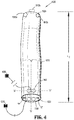
- surgical drape 1000 includes a sheath 1010 having a first end 1020, a second end 1030, and a length therebetween. It is further envisioned that first end 1020 is closed and generally spherical or hemi-spherical while second end 1030 defines an open cuff 1032 adapted for insertion of surgical tools therein. Additionally, sheath 1010 may further include a reinforced support (not shown) formed of, e.g., a rigid polymer sheet, at specific locations along the length and/or a circumference of sheath 1010, to provide a reinforced surface against which surgical tools and devices may impart destructive forces to sheath 1010, e.g., frictional forces, during use.
- a reinforced support formed of, e.g., a rigid polymer sheet, at specific locations along the length and/or a circumference of sheath 1010, to provide a reinforced surface against which surgical tools and devices may impart destructive forces to sheath 1010, e.g., frictional forces, during use.
- open cuff 1032 may be shaped and dimensioned for the passage of surgical instrument 200, instrument drive unit 300, and/or a distal portion 9 of robotic arm 2 therethrough.
- the length of sheath 1010 may further be sized to approximately correspond to the combined length from a distal end 205 of surgical instrument 200, or distal portion 9 of robotic arm 2, to a proximal end 10 of robotic arm 2, such that surgical drape 1000 can provide a protective barrier to the entire robotic arm 2 and any surgical assemblies 100 mounted thereon.
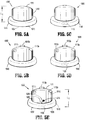
- Sheath 1010 is transitionable between an un-deployed configuration having an un-deployed length "L 1 " ( FIG. 3A ) and a deployed configuration having a deployed length "L 2 " ( FIG. 3B ), such that "L 2 " is larger than “L 1 ". It should be appreciated that the deployed length "L 2 " is user dependent and may be set at any length desired by an operator. As sheath 1010 transitions from the un-deployed configuration to the deployed configuration, and vice-versa, second end 1030 of sheath 1010 moves away from or towards first end 1020 of sheath 1010 respectively. It is envisioned that second end 1030 of sheath 1010 may rollably transition between the un-deployed configuration to the deployed configuration, and vice-versa.
- sheath 1010 As the second end 1030 of sheath 1010 is rolled towards the first end 1020 of sheath 1010, sheath 1010 also rolls towards front end 1020 such that the sheath is furled over the second end 1020 and the deployed length "L 2 " is reduced, forming a rolled sheath portion 1040 about the second end 1020.
- an operator may manually extend and transition the sheath 1010 into the deployed configuration by moving, rolling, or unfurling the second end 1030 away from first end 1020.
- Sheath 1010 may further include an access port 1012 disposed on a surface of sheath 1010 designed to permit passage of surgical instruments therethrough while maintaining a sterile barrier.
- Access port 1012 may be sized and dimensioned for passage of a variety of surgical instruments, including but not limited to, end effectors, graspers, cutters, scissors, staplers, retractors, etc. As seen in FIG. 5B , it is envisioned that there may be a plurality of access ports 1012a-c of differing sizes and dimensions provided on sheath 1010 to accommodate a wide variety of surgical instruments. Once such instrument is shown in FIG. 3B , where end effector 230 and elongate member 210 of surgical instrument 200 passes through access port 1012 a such that a sterile barrier is formed at the access port.
- surgical drape 1000 includes a plurality of stiffeners 1100 disposed on the second end 1030 of sheath 1010.
- Each stiffener 1100 may be adhered to an outer surface of sheath 1010, in or near second end 1030 of sheath 1010, and is radially disposed about the second end 1030 of sheath 1010. It should be appreciated that utilizing more than one stiffener 1100, e.g., two stiffeners 1100 radially disposed evenly about the second end 1030 of sheath 1010, may further facilitate a smooth and even transition between the deployed and un-deployed configurations. As seen in FIG.
- a longitudinal axis "A" of stiffener 1100 is generally transverse to a longitudinal axis "X" of sheath 1010.
- stiffener 1100 cooperatively moves with the second end 1030 of sheath 1010, such that the second end 1030 is rolled about the stiffener 1100 away from and towards the first end 1020.
- the second end 1030 is rolled about the stiffener 1100 it should be appreciated that a portion of sheath 1010 is also rolled or furled about stiffener 1100, forming the rolled sheath portion 1040 with stiffener 1100 and second end 1030 of sheath 1010 at the middle of the rolled sheath portion 1040.
- stiffener 1100 may take a variety of forms such as, for example, an hour glass shape 1100a ( FIG. 6A ), a rectangular shape 1100b ( FIG. 6B ), a square shape 1100c ( FIG. 6C ), or a tubular shape 1100d (6D), or any variation of the above.
- Stiffener 1100 serves to provide structural support for surgical drape 1000 such that when transitioning between the deployed and un-deployed configurations the cuff 1032 of sheath 1010 is not closed or obstructed.
- stiffener 1100 is coupled to a pull member 1200.
- each stiffener 1100 is coupled to a respective pull member 1200.
- Pull member 1200 includes a first end 1202, a second end 1204, and a length 1205 therebetween, where the first end 1202 is coupled to the stiffener 1100.
- Pull member 1200 may be coupled to stiffener 1100 through borehole 1102, or through any other suitable means known in the art, e.g., adhered, glued, tied, taped, stapled, etc. As seen in FIG.
- the length 1205 of pull member 1200 is wrapped around the longitudinal axis "A" of stiffener 1100 when second end 1030 of sheath 1010 is rolled-up or furled forming the rolled sheath portion 1040, such that the second end 1204 extends from the stiffener.
- Pull member 1200 may further include a tab 1206 disposed at the second end 1204.
- pull member 1200, stiffener 1100, and the second end 1030 of sheath 1010 act cooperatively to aid users in transitioning surgical drape 1000 from the un-deployed configuration to the deployed configuration.
- a user may move pull member 1200 in the direction of deployment as indicated by arrow "D" in FIG. 3A .
- Movement of pull member 1200 in the direction of deployment imparts a force (e.g., rotational force) upon stiffener 1100 resulting in assisted movement of the second end 1030 of sheath 1010 away from the first end 1020 of sheath 1010, which aids the unrolling or unfurling of the rolled sheath portion 1040 into the deployed length "L 2 " of sheath 1010.
- a force e.g., rotational force
- Surgical drape 1000 is provided to a user in the un-deployed configuration having the un-deployed length "L 1 ", with the second end 1030 of sheath 1010 positioned in close relation to the first end 1020 such that the rolled sheath portion 1040 is formed (as illustrated in FIG. 5E ). Further, in the un-deployed configuration the second end 1204 of pull member 1200 extends from the rolled sheath portion 1040. As seen in FIG.
- surgical instrument 200, instrument drive unit 300, or the distal portion 9 of robotic arm 2 is inserted into the open cuff 1032 of sheath 1010 such that surgical drape 1000 is mounted thereon.
- Surgical drape 1000 may be oriented such that access port 1012 is aligned with the end effector 230 or elongate member 210 of surgical instrument 200.
- FIG. 3B surgical drape 1000 is transitioned into the deployed configuration by moving the second end 1030 of sheath 1010 away from the first end 1020 in direction "D", such that the rolled sheath portion 1040 is unrolled or unfurled and the surgical drape assumes the deployed length "L 2 ".
- pull member 1200 is additionally moved in direction "D" to facilitate movement of the second end 1030 of sheath 1010 away from the first end 1020.
- stiffener 1100 cooperatively moves, rotates, un-rolls, or unfurls with the second end 1030 of sheath 1010 away from the first end 1020, providing rigidity and support to the open cuff 1032.
- the second end 1030 of sheath 1010 may be cinched closed or secured to robotic arm 2 (e.g., by tying pull members 1200), thereby forming or maintaining a sterile barrier.
- second end 1030 of sheath 1010 may be biased radially inward (indicated by arrows "R" in FIG. 4 ) such that once a user completes the deployment of surgical drape 1000 the second end 1030 of sheath 1010 cinches closed automatically to form or maintain a sterile barrier.
- sheath 1010 may be loose fitting and substantially cylindrical over robotic arm 2, or may alternatively have a pre-set or pre-defined shape for specific surgical tools or robotic arms having defined dimensions.
- a surgeon, nurse, or other operator initially inserts a portion of the surgical instrument or robotic surgical system 1 into the open cuff 1032 of sheath 1010 of surgical drape 1000 with sheath 1010 in the un-deployed configuration having the un-deployed length "L 1 ", thereby mounting surgical drape 1000 thereon.
- the operator next transitions the surgical drape 1000 to the deployed configuration by manually moving the second end 1030 of sheath 1010 away from the first end 1020. Further, the operator may move, or pull on, the pull member 1200 away from the first end 1020 of sheath 1010 to aid in the transition to the deployed configuration.
- the second end 1030 is cinched closed to create or maintain a sterile barrier. It should be appreciated that the deployed length "L 2 " is dependent upon the operator's desired area of coverage based on, for example, the surgical procedure or the instrument being used wherein a sterile barrier is desired.
Landscapes
- Health & Medical Sciences (AREA)
- Life Sciences & Earth Sciences (AREA)
- Surgery (AREA)
- Engineering & Computer Science (AREA)
- Molecular Biology (AREA)
- Public Health (AREA)
- Veterinary Medicine (AREA)
- Biomedical Technology (AREA)
- Heart & Thoracic Surgery (AREA)
- Medical Informatics (AREA)
- General Health & Medical Sciences (AREA)
- Animal Behavior & Ethology (AREA)
- Nuclear Medicine, Radiotherapy & Molecular Imaging (AREA)
- Pathology (AREA)
- Robotics (AREA)
- Oral & Maxillofacial Surgery (AREA)
- Physics & Mathematics (AREA)
- Biophysics (AREA)
- Optics & Photonics (AREA)
- Radiology & Medical Imaging (AREA)
- Manipulator (AREA)
Claims (15)
- Chirurgisches Abdecktuch (1000) für eine chirurgische Vorrichtung, wobei das chirurgische Abdecktuch Folgendes umfasst:eine Hülle (1010) einschließlich eines ersten geschlossenen Endes (1020) und eines zweiten offenen Endes (1030), die zum Einführen eines chirurgischen Instruments geeignet sind, wobei die Hülle zwischen einer nicht entfalteten Konfiguration, in der das zweite offene Ende relativ eng zu dem ersten geschlossenen Ende beabstandet ist, und einer entfalteten Konfiguration gewechselt werden kann, wobei das zweite offene Ende relativ von dem ersten geschlossenen Ende entfernt beabstandet ist;mehrere Versteifungen (1100a, 1100b, 1100c, 1100d), die neben dem zweiten offenen Ende der Hülle befestigt und radial um das zweite offene Ende der Hülle angeordnet sind; undmehrere Zugelemente (1200), die jeweils ein erstes Ende (1202), das mit einer jeweiligen Versteifung der mehreren Versteifungen gekoppelt ist, und ein zweites freies Ende (1204) beinhalten, das sowohl in der entfalteten als auch in der nicht entfalteten Konfiguration der Hülle zugänglich ist;wobei eine Länge (1205) der mehreren Zugelemente in der nicht entfalteten Konfiguration der Hülle um die mehreren Versteifungen gewickelt ist und in der entfalteten Konfiguration der Hülle von den mehreren Versteifungen abgewickelt ist.
- Chirurgisches Abdecktuch (1000) nach Anspruch 1, wobei die Hülle (1010) wenigstens teilweise im Wesentlichen zylindrisch ist und das erste geschlossene Ende (1020) im Allgemeinen halbkugelförmig ist.
- Chirurgisches Abdecktuch (1000) nach Anspruch 1 oder 2, wobei das zweite offene Ende (1030) der Hülle (1010) umgestülpt und in der nicht entfalteten Konfiguration zu dem ersten geschlossenen Ende (1020) der Hülle hin auf sich selbst gerollt ist.
- Chirurgisches Abdecktuch (1000) nach einem vorhergehenden Anspruch, wobei die Hülle (1010) aus einem flexiblen Material gefertigt ist.
- Chirurgisches Abdecktuch (1000) nach einem vorhergehenden Anspruch, wobei die mehreren Versteifungen (1100a, 1100b, 1100c, 1100d) sanduhrförmig sind und wobei die mehreren Zugelemente (1200) in einem verengten Abschnitt der mehreren Versteifungen angeordnet sind, wenn sich die Hülle (1010) in der nicht entfalteten Konfiguration befindet.
- Chirurgische Abdecktuch (1000) nach einem vorhergehenden Anspruch, ferner beinhaltend eine Zuglasche (1206), die an dem zweiten freien Ende (1204) der mehreren Zugelemente (1200) angeordnet ist.
- Chirurgisches Abdecktuch (1000) nach einem vorhergehenden Anspruch, wobei das zweite offene Ende (1030) der Hülle (1010) radial nach innen vorgespannt ist.
- Chirurgisches Abdecktuch (1000) nach einem vorhergehenden Anspruch, wobei die mehreren Versteifungen (1100a, 1100b, 1100c, 1100d) radial gleichmäßig um das zweite offene Ende (1030) der Hülle (1010) angeordnet sind.
- Chirurgische Abdecktuch (1000) nach einem vorhergehenden Anspruch, ferner beinhaltend wenigstens eine Zugangsöffnung (1012a, 1012b, 1012c), die neben dem ersten geschlossenen Ende (1020) der Hülle (1010) ausgebildet ist.
- Chirurgisches Abdecktuch (1000) nach Anspruch 1, wobei die nicht entfaltete Konfiguration der Hülle (1010) eine gerollte Konfiguration ist, wobei die mehreren Zugelemente (1200) in die Hülle und um die mehreren Versteifungen (1100a, 1100b, 1100c, 1100d) gerollt sind, wenn sich die Hülle in der nicht entfalteten Konfiguration befindet.
- Chirurgische Roboteranordnung (1), Folgendes umfassend:einen Roboterarm (2, 3); unddas chirurgische Abdecktuch (1000) nach Anspruch 9;wobei die Hülle (1010) des chirurgischen Abdecktuchs eine sterile Barriere zwischen dem Roboterarm und einer äußeren Umgebung bereitstellt.
- Verfahren zum Beibehalten eines sterilen chirurgischen Instruments, wobei das Verfahren Folgendes umfasst:Bereitstellen eines chirurgischen Instruments (100);Platzieren des zweiten offenen Endes (1030) der Hülle (1010) des chirurgischen Abdecktuchs (1000) nach einem der Ansprüche 1 bis 10 über dem chirurgischen Instrument, während sich die Hülle in der nicht entfalteten Konfiguration befindet, in der ein Abschnitt der Hülle auf sich selbst zusammengerollt ist; undmanuelles Wechseln der Hülle in die entfaltete Konfiguration durch das Aufrollen des zusammengerollten Abschnitts der Hülle, sodass die Hülle einen gewünschten Abschnitt des chirurgischen Instruments abdeckt.
- Verfahren nach Anspruch 12, wobei das manuelle Wechseln der Hülle (1010) in die entfaltete Konfiguration das Ziehen der mehreren Zugelemente (1200) beinhaltet, um den zusammengerollten Abschnitt der Hülle aufzurollen.
- Verfahren nach Anspruch 12 oder 13, ferner beinhaltend das Befestigen des zweiten offenen Endes (1030) der Hülle (1010) an dem chirurgischen Instrument (100) an einer gewünschten Position, um eine sterile Barriere zu bilden.
- Verfahren nach einem der Ansprüche 12 bis 14, wobei sich das chirurgische Instrument (100) an dem Ende eines chirurgischen Roboterarms (2, 3) befindet und das manuelle Wechseln der Hülle (1010) in die entfaltete Konfiguration das Aufrollen des zusammengerollten Abschnitts der Hülle beinhaltet, sodass die Hülle einen gewünschten Abschnitt des chirurgischen Roboterarms abdeckt.
Applications Claiming Priority (2)
| Application Number | Priority Date | Filing Date | Title |
|---|---|---|---|
| US201562168952P | 2015-06-01 | 2015-06-01 | |
| PCT/US2016/034257 WO2016196165A1 (en) | 2015-06-01 | 2016-05-26 | Surgical drape including unrolling mechanism |
Publications (3)
| Publication Number | Publication Date |
|---|---|
| EP3302336A1 EP3302336A1 (de) | 2018-04-11 |
| EP3302336A4 EP3302336A4 (de) | 2019-01-23 |
| EP3302336B1 true EP3302336B1 (de) | 2020-12-30 |
Family
ID=57441703
Family Applications (1)
| Application Number | Title | Priority Date | Filing Date |
|---|---|---|---|
| EP16804051.7A Active EP3302336B1 (de) | 2015-06-01 | 2016-05-26 | Chirurgisches abdecktuch mit abrollmechanismus |
Country Status (5)
| Country | Link |
|---|---|
| US (1) | US11389258B2 (de) |
| EP (1) | EP3302336B1 (de) |
| JP (1) | JP6737814B2 (de) |
| CN (1) | CN107771062B (de) |
| WO (1) | WO2016196165A1 (de) |
Families Citing this family (10)
| Publication number | Priority date | Publication date | Assignee | Title |
|---|---|---|---|---|
| CN110621256A (zh) * | 2017-05-24 | 2019-12-27 | 柯惠Lp公司 | 用于机器人系统的外科手术套管 |
| JP2020520694A (ja) | 2017-05-25 | 2020-07-16 | コヴィディエン リミテッド パートナーシップ | ロボット手術システムおよびロボット手術システムのコンポーネントを覆うためのドレープ |
| US11628029B2 (en) * | 2017-09-13 | 2023-04-18 | Intuitive Surgical Operations, Inc. | Surgical drape cooling |
| US11096754B2 (en) | 2017-10-04 | 2021-08-24 | Mako Surgical Corp. | Sterile drape assembly for surgical robot |
| DE102018213499B4 (de) * | 2018-08-10 | 2021-07-08 | Kuka Deutschland Gmbh | Roboterarm mit über wenigstens ein linienförmiges Verbindungselement verbundenen Gehäuseschalen |
| JP6902003B2 (ja) | 2018-08-28 | 2021-07-14 | 株式会社メディカロイド | 滅菌ドレープおよび手術器具の取付方法 |
| US11471233B2 (en) * | 2019-04-30 | 2022-10-18 | Canon U.S.A., Inc. | Preloaded sterile bag |
| WO2021186218A1 (en) * | 2020-03-19 | 2021-09-23 | Stryker European Holdings I, Llc | Device for computer-assisted surgery having two arms and method for operating the same |
| US20220249188A1 (en) * | 2021-02-08 | 2022-08-11 | Mark McBride | Surgical drape having an extendable sleeve for covering a surgical instrument and methods of making and using same |
| US11903669B2 (en) | 2021-07-30 | 2024-02-20 | Corindus, Inc | Sterile drape for robotic drive |
Citations (2)
| Publication number | Priority date | Publication date | Assignee | Title |
|---|---|---|---|---|
| WO2003049623A1 (en) * | 2001-12-13 | 2003-06-19 | Oneg Hakarmel | Device and method for excluding blood out of a limb |
| DE102008017898A1 (de) * | 2007-06-08 | 2008-12-11 | Jolanta Elzbieta Lode | Überzug für ein chirurgisches Instrument |
Family Cites Families (22)
| Publication number | Priority date | Publication date | Assignee | Title |
|---|---|---|---|---|
| US4308864A (en) * | 1979-02-09 | 1982-01-05 | Small Martin H | Surgical extremity drape |
| US4308867A (en) * | 1979-03-23 | 1982-01-05 | Roseman Theodore J | Two-member medicated device for rate-controlled administration of lipophilic pharmaceuticals |
| JP3141165B2 (ja) | 1991-07-25 | 2001-03-05 | 本田技研工業株式会社 | Rom構成の照合方法 |
| US5358495A (en) * | 1993-02-01 | 1994-10-25 | Lynn Lawrence A | Sterile guidewire exchange system |
| US5591119A (en) | 1994-12-07 | 1997-01-07 | Adair; Edwin L. | Sterile surgical coupler and drape |
| AU762415B2 (en) * | 1999-01-19 | 2003-06-26 | Covidien Lp | Sheath and applicator for surgical instrument |
| EP1295568A1 (de) * | 2001-09-20 | 2003-03-26 | Carl Zeiss | Mit Abdeckvorrichtung versehenes Instrument |
| US6536636B1 (en) * | 2001-11-26 | 2003-03-25 | Mcdonniel Thomas B. | Support hose applicator |
| AU2003282949A1 (en) * | 2002-10-17 | 2004-05-04 | Microtek Medical, Inc. | System and method for removing a protective cover from a medical instrument |
| CA2684559C (en) | 2007-04-16 | 2017-09-12 | Neuroarm Surgical Ltd. | Devices for interfacing between manipulators and surgical tools |
| US8945148B2 (en) * | 2007-06-13 | 2015-02-03 | Intuitive Surgical Operations, Inc. | Surgical system instrument manipulator |
| DE102008005901B4 (de) | 2008-01-24 | 2018-08-09 | Deutsches Zentrum für Luft- und Raumfahrt e.V. | Sterilbarriere für einen chirurgischen Roboter mit Drehmomentsensoren |
| JP3141165U (ja) * | 2008-02-12 | 2008-04-24 | 艶金化学繊維株式会社 | 作業ロボット用保護カバー |
| US20130125901A1 (en) * | 2010-10-20 | 2013-05-23 | Christos Pitaoulis | Disposable radial access catheterization sleeve |
| DE102010043584A1 (de) | 2010-11-08 | 2012-05-10 | Kuka Laboratories Gmbh | Medizinscher Arbeitsplatz |
| CN202036341U (zh) | 2011-03-26 | 2011-11-16 | 汕头大学医学院第一附属医院 | 一种骨科手术用肢体隔离套 |
| JP5820601B2 (ja) * | 2011-03-31 | 2015-11-24 | オリンパス株式会社 | マスタマニピュレータ |
| JP5931497B2 (ja) * | 2011-08-04 | 2016-06-08 | オリンパス株式会社 | 手術支援装置およびその組立方法 |
| US10285767B2 (en) * | 2013-03-14 | 2019-05-14 | Source Surgical, Inc. | Medical drape and methods of covering equipment with medical drapes |
| US10080552B2 (en) | 2014-04-21 | 2018-09-25 | Covidien Lp | Adapter assembly with gimbal for interconnecting electromechanical surgical devices and surgical loading units, and surgical systems thereof |
| CN106456256B (zh) | 2014-05-13 | 2019-03-26 | 柯惠Lp公司 | 机器人手术系统和器械驱动单元 |
| US10044792B2 (en) * | 2014-06-02 | 2018-08-07 | Ohk Medical Devices, Ltd. | Method and system for optimization of an exsanguination tourniquet |
-
2016
- 2016-05-26 JP JP2017560973A patent/JP6737814B2/ja not_active Expired - Fee Related
- 2016-05-26 US US15/573,984 patent/US11389258B2/en active Active
- 2016-05-26 CN CN201680031934.9A patent/CN107771062B/zh active Active
- 2016-05-26 WO PCT/US2016/034257 patent/WO2016196165A1/en active Application Filing
- 2016-05-26 EP EP16804051.7A patent/EP3302336B1/de active Active
Patent Citations (2)
| Publication number | Priority date | Publication date | Assignee | Title |
|---|---|---|---|---|
| WO2003049623A1 (en) * | 2001-12-13 | 2003-06-19 | Oneg Hakarmel | Device and method for excluding blood out of a limb |
| DE102008017898A1 (de) * | 2007-06-08 | 2008-12-11 | Jolanta Elzbieta Lode | Überzug für ein chirurgisches Instrument |
Also Published As
| Publication number | Publication date |
|---|---|
| EP3302336A1 (de) | 2018-04-11 |
| EP3302336A4 (de) | 2019-01-23 |
| US11389258B2 (en) | 2022-07-19 |
| WO2016196165A1 (en) | 2016-12-08 |
| CN107771062A (zh) | 2018-03-06 |
| US20180289438A1 (en) | 2018-10-11 |
| JP2018521721A (ja) | 2018-08-09 |
| CN107771062B (zh) | 2021-04-13 |
| JP6737814B2 (ja) | 2020-08-12 |
Similar Documents
| Publication | Publication Date | Title |
|---|---|---|
| EP3302336B1 (de) | Chirurgisches abdecktuch mit abrollmechanismus | |
| US10639113B2 (en) | Robotic surgical systems and instrument drive units | |
| JP6634446B2 (ja) | 外科手術用ポートアセンブリを使用して外科手術用器具を制御する方法および装置 | |
| US11045268B2 (en) | Instrument drive unit including lead screw rails | |
| JP5193049B2 (ja) | 外科手術用滅菌ドレープ | |
| CN110604619B (zh) | 手术系统无菌帷帘 | |
| US20050096502A1 (en) | Robotic surgical device | |
| AU2016247965A1 (en) | Methods for exchanging instruments using a surgical port assembly | |
| US10973599B2 (en) | Surgical platform supported by multiple arms | |
| US20200085524A1 (en) | Surgical sleeve for robotic systems | |
| US11523817B2 (en) | Endoluminal pursestring device | |
| Johnson | Design of a surgical manipulator system for lumbar discectomy procedures | |
| EFFECTORS | THULLULUWUTTUR |
Legal Events
| Date | Code | Title | Description |
|---|---|---|---|
| STAA | Information on the status of an ep patent application or granted ep patent |
Free format text: STATUS: THE INTERNATIONAL PUBLICATION HAS BEEN MADE |
|
| PUAI | Public reference made under article 153(3) epc to a published international application that has entered the european phase |
Free format text: ORIGINAL CODE: 0009012 |
|
| STAA | Information on the status of an ep patent application or granted ep patent |
Free format text: STATUS: REQUEST FOR EXAMINATION WAS MADE |
|
| 17P | Request for examination filed |
Effective date: 20171222 |
|
| AK | Designated contracting states |
Kind code of ref document: A1 Designated state(s): AL AT BE BG CH CY CZ DE DK EE ES FI FR GB GR HR HU IE IS IT LI LT LU LV MC MK MT NL NO PL PT RO RS SE SI SK SM TR |
|
| AX | Request for extension of the european patent |
Extension state: BA ME |
|
| DAV | Request for validation of the european patent (deleted) | ||
| DAX | Request for extension of the european patent (deleted) | ||
| REG | Reference to a national code |
Ref country code: DE Ref legal event code: R079 Ref document number: 602016050701 Country of ref document: DE Free format text: PREVIOUS MAIN CLASS: A61B0046200000 Ipc: A61B0046100000 |
|
| A4 | Supplementary search report drawn up and despatched |
Effective date: 20181220 |
|
| RIC1 | Information provided on ipc code assigned before grant |
Ipc: A61B 46/10 20160101AFI20181214BHEP Ipc: A61B 34/35 20160101ALI20181214BHEP Ipc: A61B 90/50 20160101ALI20181214BHEP |
|
| STAA | Information on the status of an ep patent application or granted ep patent |
Free format text: STATUS: EXAMINATION IS IN PROGRESS |
|
| 17Q | First examination report despatched |
Effective date: 20200309 |
|
| GRAP | Despatch of communication of intention to grant a patent |
Free format text: ORIGINAL CODE: EPIDOSNIGR1 |
|
| STAA | Information on the status of an ep patent application or granted ep patent |
Free format text: STATUS: GRANT OF PATENT IS INTENDED |
|
| INTG | Intention to grant announced |
Effective date: 20200805 |
|
| GRAS | Grant fee paid |
Free format text: ORIGINAL CODE: EPIDOSNIGR3 |
|
| GRAA | (expected) grant |
Free format text: ORIGINAL CODE: 0009210 |
|
| STAA | Information on the status of an ep patent application or granted ep patent |
Free format text: STATUS: THE PATENT HAS BEEN GRANTED |
|
| AK | Designated contracting states |
Kind code of ref document: B1 Designated state(s): AL AT BE BG CH CY CZ DE DK EE ES FI FR GB GR HR HU IE IS IT LI LT LU LV MC MK MT NL NO PL PT RO RS SE SI SK SM TR |
|
| REG | Reference to a national code |
Ref country code: GB Ref legal event code: FG4D |
|
| REG | Reference to a national code |
Ref country code: DE Ref legal event code: R096 Ref document number: 602016050701 Country of ref document: DE |
|
| REG | Reference to a national code |
Ref country code: AT Ref legal event code: REF Ref document number: 1349148 Country of ref document: AT Kind code of ref document: T Effective date: 20210115 |
|
| REG | Reference to a national code |
Ref country code: IE Ref legal event code: FG4D |
|
| REG | Reference to a national code |
Ref country code: DE Ref legal event code: R082 Ref document number: 602016050701 Country of ref document: DE Representative=s name: WR SERVICES GMBH, DE |
|
| PG25 | Lapsed in a contracting state [announced via postgrant information from national office to epo] |
Ref country code: NO Free format text: LAPSE BECAUSE OF FAILURE TO SUBMIT A TRANSLATION OF THE DESCRIPTION OR TO PAY THE FEE WITHIN THE PRESCRIBED TIME-LIMIT Effective date: 20210330 Ref country code: RS Free format text: LAPSE BECAUSE OF FAILURE TO SUBMIT A TRANSLATION OF THE DESCRIPTION OR TO PAY THE FEE WITHIN THE PRESCRIBED TIME-LIMIT Effective date: 20201230 Ref country code: FI Free format text: LAPSE BECAUSE OF FAILURE TO SUBMIT A TRANSLATION OF THE DESCRIPTION OR TO PAY THE FEE WITHIN THE PRESCRIBED TIME-LIMIT Effective date: 20201230 Ref country code: GR Free format text: LAPSE BECAUSE OF FAILURE TO SUBMIT A TRANSLATION OF THE DESCRIPTION OR TO PAY THE FEE WITHIN THE PRESCRIBED TIME-LIMIT Effective date: 20210331 |
|
| REG | Reference to a national code |
Ref country code: AT Ref legal event code: MK05 Ref document number: 1349148 Country of ref document: AT Kind code of ref document: T Effective date: 20201230 |
|
| PG25 | Lapsed in a contracting state [announced via postgrant information from national office to epo] |
Ref country code: SE Free format text: LAPSE BECAUSE OF FAILURE TO SUBMIT A TRANSLATION OF THE DESCRIPTION OR TO PAY THE FEE WITHIN THE PRESCRIBED TIME-LIMIT Effective date: 20201230 Ref country code: BG Free format text: LAPSE BECAUSE OF FAILURE TO SUBMIT A TRANSLATION OF THE DESCRIPTION OR TO PAY THE FEE WITHIN THE PRESCRIBED TIME-LIMIT Effective date: 20210330 Ref country code: LV Free format text: LAPSE BECAUSE OF FAILURE TO SUBMIT A TRANSLATION OF THE DESCRIPTION OR TO PAY THE FEE WITHIN THE PRESCRIBED TIME-LIMIT Effective date: 20201230 |
|
| REG | Reference to a national code |
Ref country code: NL Ref legal event code: MP Effective date: 20201230 |
|
| PG25 | Lapsed in a contracting state [announced via postgrant information from national office to epo] |
Ref country code: HR Free format text: LAPSE BECAUSE OF FAILURE TO SUBMIT A TRANSLATION OF THE DESCRIPTION OR TO PAY THE FEE WITHIN THE PRESCRIBED TIME-LIMIT Effective date: 20201230 |
|
| REG | Reference to a national code |
Ref country code: LT Ref legal event code: MG9D |
|
| PG25 | Lapsed in a contracting state [announced via postgrant information from national office to epo] |
Ref country code: LT Free format text: LAPSE BECAUSE OF FAILURE TO SUBMIT A TRANSLATION OF THE DESCRIPTION OR TO PAY THE FEE WITHIN THE PRESCRIBED TIME-LIMIT Effective date: 20201230 Ref country code: EE Free format text: LAPSE BECAUSE OF FAILURE TO SUBMIT A TRANSLATION OF THE DESCRIPTION OR TO PAY THE FEE WITHIN THE PRESCRIBED TIME-LIMIT Effective date: 20201230 Ref country code: CZ Free format text: LAPSE BECAUSE OF FAILURE TO SUBMIT A TRANSLATION OF THE DESCRIPTION OR TO PAY THE FEE WITHIN THE PRESCRIBED TIME-LIMIT Effective date: 20201230 Ref country code: PT Free format text: LAPSE BECAUSE OF FAILURE TO SUBMIT A TRANSLATION OF THE DESCRIPTION OR TO PAY THE FEE WITHIN THE PRESCRIBED TIME-LIMIT Effective date: 20210430 Ref country code: RO Free format text: LAPSE BECAUSE OF FAILURE TO SUBMIT A TRANSLATION OF THE DESCRIPTION OR TO PAY THE FEE WITHIN THE PRESCRIBED TIME-LIMIT Effective date: 20201230 Ref country code: SK Free format text: LAPSE BECAUSE OF FAILURE TO SUBMIT A TRANSLATION OF THE DESCRIPTION OR TO PAY THE FEE WITHIN THE PRESCRIBED TIME-LIMIT Effective date: 20201230 |
|
| PG25 | Lapsed in a contracting state [announced via postgrant information from national office to epo] |
Ref country code: AT Free format text: LAPSE BECAUSE OF FAILURE TO SUBMIT A TRANSLATION OF THE DESCRIPTION OR TO PAY THE FEE WITHIN THE PRESCRIBED TIME-LIMIT Effective date: 20201230 Ref country code: PL Free format text: LAPSE BECAUSE OF FAILURE TO SUBMIT A TRANSLATION OF THE DESCRIPTION OR TO PAY THE FEE WITHIN THE PRESCRIBED TIME-LIMIT Effective date: 20201230 |
|
| PG25 | Lapsed in a contracting state [announced via postgrant information from national office to epo] |
Ref country code: IS Free format text: LAPSE BECAUSE OF FAILURE TO SUBMIT A TRANSLATION OF THE DESCRIPTION OR TO PAY THE FEE WITHIN THE PRESCRIBED TIME-LIMIT Effective date: 20210430 |
|
| REG | Reference to a national code |
Ref country code: DE Ref legal event code: R097 Ref document number: 602016050701 Country of ref document: DE |
|
| PG25 | Lapsed in a contracting state [announced via postgrant information from national office to epo] |
Ref country code: AL Free format text: LAPSE BECAUSE OF FAILURE TO SUBMIT A TRANSLATION OF THE DESCRIPTION OR TO PAY THE FEE WITHIN THE PRESCRIBED TIME-LIMIT Effective date: 20201230 Ref country code: IT Free format text: LAPSE BECAUSE OF FAILURE TO SUBMIT A TRANSLATION OF THE DESCRIPTION OR TO PAY THE FEE WITHIN THE PRESCRIBED TIME-LIMIT Effective date: 20201230 |
|
| PLBE | No opposition filed within time limit |
Free format text: ORIGINAL CODE: 0009261 |
|
| STAA | Information on the status of an ep patent application or granted ep patent |
Free format text: STATUS: NO OPPOSITION FILED WITHIN TIME LIMIT |
|
| PG25 | Lapsed in a contracting state [announced via postgrant information from national office to epo] |
Ref country code: DK Free format text: LAPSE BECAUSE OF FAILURE TO SUBMIT A TRANSLATION OF THE DESCRIPTION OR TO PAY THE FEE WITHIN THE PRESCRIBED TIME-LIMIT Effective date: 20201230 |
|
| 26N | No opposition filed |
Effective date: 20211001 |
|
| REG | Reference to a national code |
Ref country code: CH Ref legal event code: PL |
|
| GBPC | Gb: european patent ceased through non-payment of renewal fee |
Effective date: 20210526 |
|
| PG25 | Lapsed in a contracting state [announced via postgrant information from national office to epo] |
Ref country code: ES Free format text: LAPSE BECAUSE OF FAILURE TO SUBMIT A TRANSLATION OF THE DESCRIPTION OR TO PAY THE FEE WITHIN THE PRESCRIBED TIME-LIMIT Effective date: 20201230 Ref country code: LU Free format text: LAPSE BECAUSE OF NON-PAYMENT OF DUE FEES Effective date: 20210526 Ref country code: LI Free format text: LAPSE BECAUSE OF NON-PAYMENT OF DUE FEES Effective date: 20210531 Ref country code: MC Free format text: LAPSE BECAUSE OF FAILURE TO SUBMIT A TRANSLATION OF THE DESCRIPTION OR TO PAY THE FEE WITHIN THE PRESCRIBED TIME-LIMIT Effective date: 20201230 Ref country code: CH Free format text: LAPSE BECAUSE OF NON-PAYMENT OF DUE FEES Effective date: 20210531 |
|
| REG | Reference to a national code |
Ref country code: BE Ref legal event code: MM Effective date: 20210531 |
|
| PG25 | Lapsed in a contracting state [announced via postgrant information from national office to epo] |
Ref country code: SI Free format text: LAPSE BECAUSE OF FAILURE TO SUBMIT A TRANSLATION OF THE DESCRIPTION OR TO PAY THE FEE WITHIN THE PRESCRIBED TIME-LIMIT Effective date: 20201230 |
|
| PG25 | Lapsed in a contracting state [announced via postgrant information from national office to epo] |
Ref country code: IE Free format text: LAPSE BECAUSE OF NON-PAYMENT OF DUE FEES Effective date: 20210526 Ref country code: GB Free format text: LAPSE BECAUSE OF NON-PAYMENT OF DUE FEES Effective date: 20210526 |
|
| PG25 | Lapsed in a contracting state [announced via postgrant information from national office to epo] |
Ref country code: IS Free format text: LAPSE BECAUSE OF FAILURE TO SUBMIT A TRANSLATION OF THE DESCRIPTION OR TO PAY THE FEE WITHIN THE PRESCRIBED TIME-LIMIT Effective date: 20210430 Ref country code: FR Free format text: LAPSE BECAUSE OF NON-PAYMENT OF DUE FEES Effective date: 20210531 |
|
| PG25 | Lapsed in a contracting state [announced via postgrant information from national office to epo] |
Ref country code: BE Free format text: LAPSE BECAUSE OF NON-PAYMENT OF DUE FEES Effective date: 20210531 |
|
| PG25 | Lapsed in a contracting state [announced via postgrant information from national office to epo] |
Ref country code: HU Free format text: LAPSE BECAUSE OF FAILURE TO SUBMIT A TRANSLATION OF THE DESCRIPTION OR TO PAY THE FEE WITHIN THE PRESCRIBED TIME-LIMIT; INVALID AB INITIO Effective date: 20160526 |
|
| PG25 | Lapsed in a contracting state [announced via postgrant information from national office to epo] |
Ref country code: NL Free format text: LAPSE BECAUSE OF NON-PAYMENT OF DUE FEES Effective date: 20201230 Ref country code: CY Free format text: LAPSE BECAUSE OF FAILURE TO SUBMIT A TRANSLATION OF THE DESCRIPTION OR TO PAY THE FEE WITHIN THE PRESCRIBED TIME-LIMIT Effective date: 20201230 |
|
| PG25 | Lapsed in a contracting state [announced via postgrant information from national office to epo] |
Ref country code: SM Free format text: LAPSE BECAUSE OF FAILURE TO SUBMIT A TRANSLATION OF THE DESCRIPTION OR TO PAY THE FEE WITHIN THE PRESCRIBED TIME-LIMIT Effective date: 20201230 |
|
| PGFP | Annual fee paid to national office [announced via postgrant information from national office to epo] |
Ref country code: DE Payment date: 20230419 Year of fee payment: 8 |
|
| PG25 | Lapsed in a contracting state [announced via postgrant information from national office to epo] |
Ref country code: MK Free format text: LAPSE BECAUSE OF FAILURE TO SUBMIT A TRANSLATION OF THE DESCRIPTION OR TO PAY THE FEE WITHIN THE PRESCRIBED TIME-LIMIT Effective date: 20201230 |