EP3302155B1 - Dispositif de tensionnement motorisé comprenant un système de bobine compact - Google Patents
Dispositif de tensionnement motorisé comprenant un système de bobine compact Download PDFInfo
- Publication number
- EP3302155B1 EP3302155B1 EP16728437.1A EP16728437A EP3302155B1 EP 3302155 B1 EP3302155 B1 EP 3302155B1 EP 16728437 A EP16728437 A EP 16728437A EP 3302155 B1 EP3302155 B1 EP 3302155B1
- Authority
- EP
- European Patent Office
- Prior art keywords
- lace
- reel
- reel member
- article
- footwear
- Prior art date
- Legal status (The legal status is an assumption and is not a legal conclusion. Google has not performed a legal analysis and makes no representation as to the accuracy of the status listed.)
- Active
Links
- 230000009467 reduction Effects 0.000 claims description 41
- 238000004804 winding Methods 0.000 claims description 22
- 210000000452 mid-foot Anatomy 0.000 claims description 8
- 230000004044 response Effects 0.000 claims description 5
- 210000002683 foot Anatomy 0.000 description 30
- 230000007246 mechanism Effects 0.000 description 12
- 210000004744 fore-foot Anatomy 0.000 description 6
- 210000000474 heel Anatomy 0.000 description 6
- 239000000463 material Substances 0.000 description 5
- 238000000034 method Methods 0.000 description 5
- 230000001965 increasing effect Effects 0.000 description 4
- 230000000712 assembly Effects 0.000 description 3
- 238000000429 assembly Methods 0.000 description 3
- 230000005540 biological transmission Effects 0.000 description 3
- 230000008878 coupling Effects 0.000 description 3
- 238000010168 coupling process Methods 0.000 description 3
- 238000005859 coupling reaction Methods 0.000 description 3
- 238000005516 engineering process Methods 0.000 description 3
- 230000004913 activation Effects 0.000 description 2
- 230000033001 locomotion Effects 0.000 description 2
- 229920000642 polymer Polymers 0.000 description 2
- 210000003371 toe Anatomy 0.000 description 2
- 239000011800 void material Substances 0.000 description 2
- WHXSMMKQMYFTQS-UHFFFAOYSA-N Lithium Chemical compound [Li] WHXSMMKQMYFTQS-UHFFFAOYSA-N 0.000 description 1
- 239000000853 adhesive Substances 0.000 description 1
- 230000001070 adhesive effect Effects 0.000 description 1
- 210000003423 ankle Anatomy 0.000 description 1
- 238000013459 approach Methods 0.000 description 1
- 230000000386 athletic effect Effects 0.000 description 1
- 210000000459 calcaneus Anatomy 0.000 description 1
- 238000006243 chemical reaction Methods 0.000 description 1
- 230000003247 decreasing effect Effects 0.000 description 1
- 230000000694 effects Effects 0.000 description 1
- 239000000835 fiber Substances 0.000 description 1
- 239000002657 fibrous material Substances 0.000 description 1
- 239000006260 foam Substances 0.000 description 1
- 238000003306 harvesting Methods 0.000 description 1
- 230000006698 induction Effects 0.000 description 1
- 230000001939 inductive effect Effects 0.000 description 1
- 230000000977 initiatory effect Effects 0.000 description 1
- 238000002955 isolation Methods 0.000 description 1
- 239000010410 layer Substances 0.000 description 1
- 239000010985 leather Substances 0.000 description 1
- 239000002649 leather substitute Substances 0.000 description 1
- 229910052744 lithium Inorganic materials 0.000 description 1
- 210000001872 metatarsal bone Anatomy 0.000 description 1
- 238000000465 moulding Methods 0.000 description 1
- 230000001681 protective effect Effects 0.000 description 1
- 230000002441 reversible effect Effects 0.000 description 1
- 238000001228 spectrum Methods 0.000 description 1
- 230000001360 synchronised effect Effects 0.000 description 1
- 239000004753 textile Substances 0.000 description 1
- 229920000785 ultra high molecular weight polyethylene Polymers 0.000 description 1
Images


Classifications
-
- A—HUMAN NECESSITIES
- A43—FOOTWEAR
- A43C—FASTENINGS OR ATTACHMENTS OF FOOTWEAR; LACES IN GENERAL
- A43C11/00—Other fastenings specially adapted for shoes
- A43C11/16—Fastenings secured by wire, bolts, or the like
-
- A—HUMAN NECESSITIES
- A43—FOOTWEAR
- A43C—FASTENINGS OR ATTACHMENTS OF FOOTWEAR; LACES IN GENERAL
- A43C11/00—Other fastenings specially adapted for shoes
- A43C11/16—Fastenings secured by wire, bolts, or the like
- A43C11/165—Fastenings secured by wire, bolts, or the like characterised by a spool, reel or pulley for winding up cables, laces or straps by rotation
-
- A—HUMAN NECESSITIES
- A43—FOOTWEAR
- A43B—CHARACTERISTIC FEATURES OF FOOTWEAR; PARTS OF FOOTWEAR
- A43B11/00—Footwear with arrangements to facilitate putting-on or removing, e.g. with straps
-
- A—HUMAN NECESSITIES
- A43—FOOTWEAR
- A43B—CHARACTERISTIC FEATURES OF FOOTWEAR; PARTS OF FOOTWEAR
- A43B13/00—Soles; Sole-and-heel integral units
- A43B13/14—Soles; Sole-and-heel integral units characterised by the constructive form
-
- A—HUMAN NECESSITIES
- A43—FOOTWEAR
- A43B—CHARACTERISTIC FEATURES OF FOOTWEAR; PARTS OF FOOTWEAR
- A43B3/00—Footwear characterised by the shape or the use
- A43B3/34—Footwear characterised by the shape or the use with electrical or electronic arrangements
-
- A—HUMAN NECESSITIES
- A43—FOOTWEAR
- A43B—CHARACTERISTIC FEATURES OF FOOTWEAR; PARTS OF FOOTWEAR
- A43B3/00—Footwear characterised by the shape or the use
- A43B3/34—Footwear characterised by the shape or the use with electrical or electronic arrangements
- A43B3/38—Footwear characterised by the shape or the use with electrical or electronic arrangements with power sources
- A43B3/40—Batteries
-
- A—HUMAN NECESSITIES
- A43—FOOTWEAR
- A43C—FASTENINGS OR ATTACHMENTS OF FOOTWEAR; LACES IN GENERAL
- A43C1/00—Shoe lacing fastenings
-
- A—HUMAN NECESSITIES
- A43—FOOTWEAR
- A43C—FASTENINGS OR ATTACHMENTS OF FOOTWEAR; LACES IN GENERAL
- A43C11/00—Other fastenings specially adapted for shoes
- A43C11/14—Clamp fastenings, e.g. strap fastenings; Clamp-buckle fastenings; Fastenings with toggle levers
-
- A—HUMAN NECESSITIES
- A43—FOOTWEAR
- A43C—FASTENINGS OR ATTACHMENTS OF FOOTWEAR; LACES IN GENERAL
- A43C7/00—Holding-devices for laces
- A43C7/08—Clamps drawn tight by laces
Definitions
- the present application relates generally to articles of footwear including tensioning systems.
- Articles of footwear generally include two primary elements: an upper and a sole structure.
- the upper is often formed from a plurality of material elements (e.g., textiles, polymer sheet layers, foam layers, leather, synthetic leather) that are stitched or adhesively bonded together to form a void on the interior of the footwear for comfortably and securely receiving a foot. More particularly, the upper forms a structure that extends over instep and toe areas of the foot, along medial and lateral sides of the foot, and around a heel area of the foot.
- the upper may also incorporate a lacing system to adjust the fit of the footwear, as well as permitting entry and removal of the foot from the void within the upper.
- some articles of apparel may include various kinds of closure systems for adjusting the fit of the apparel.
- a known article of footwear having a closure system for adjusting the fit of the article is described in WO2009/071652 .
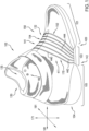
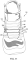
- FIG. 1 illustrates a schematic side view of an embodiment of article of footwear 100 that is configured with a tensioning system 150.
- article of footwear 100 also referred to hereafter simply as article 100
- tensioning system 150 may be used with any other kind of footwear including, but not limited to: hiking boots, soccer shoes, football shoes, sneakers, running shoes, cross-training shoes, rugby shoes, basketball shoes, baseball shoes as well as other kinds of shoes.
- article 100 may be configured for use with various kinds of non-sports related footwear, including, but not limited to: slippers, sandals, high heeled footwear, loafers as well as any other kinds of footwear.
- a tensioning system may not be limited to footwear and in other embodiments a tensioning system could be used with various kinds of apparel, including clothing, sportswear, sporting equipment and other kinds of apparel.
- a tensioning system may be used with braces, such as medical braces.
- article 100 is divided into forefoot region 101, midfoot region 103 and heel region 105.
- Forefoot region 101 may be generally associated with the toes and joints connecting the metatarsals with the phalanges.
- Midfoot region 103 may be generally associated with the arch of a foot.
- heel region 105 may be generally associated with the heel of a foot, including the calcaneus bone. It will be understood that forefoot region 101, midfoot region 103 and heel region 105 are only intended for purposes of description and are not intended to demarcate precise regions of article 100.
- lateral or lateral direction refers to a direction extending along a width of a component or element.
- a lateral axis 191 of article may extend between a medial side 141 and a lateral side 143 of the foot.
- longitudinal or “longitudinal direction” as used throughout this detailed description and in the claims refers to a direction extending across a length or breadth of an element or component (such as a sole member).
- a longitudinal axis 181 may extend from forefoot region 101 to heel region 105 of a foot.
- each of these directional adjectives may also be applied to individual components of an article of footwear, such as an upper and/or a sole member.
- a vertical axis 171 refers to the axis perpendicular to a horizontal surface defined by longitudinal axis 181 and lateral axis 191. It will be understood that each of these directional adjectives may be applied to various components shown in the embodiments, including article 100, as well as components of tensioning system 150.
- Article 100 includes upper 102 and sole structure 104.
- upper 102 may be any type of upper.
- upper 102 may have any design, shape, size and/or color.
- upper 102 could be a high top upper that is shaped to provide high support on an ankle.
- upper 102 could be a low top upper.
- sole structure 104 may be configured to provide traction for article 100. In addition to providing traction, sole structure 104 may attenuate ground reaction forces when compressed between the foot and the ground during walking, running or other ambulatory activities.
- the configuration of sole structure 104 may vary significantly in different embodiments to include a variety of conventional or non-conventional structures. In some cases, the configuration of sole structure 104 can be configured according to one or more types of ground surfaces on which sole structure 104 may be used. Examples of ground surfaces include, but are not limited to: natural turf, synthetic turf, dirt, as well as other surfaces.
- sole structure 104 may include different components.
- sole structure 104 may include an outsole, a midsole, and/or an insole.
- sole structure 104 can include one or more cleat members or traction elements that are configured to increase traction with a ground surface.
- Sole structure 104 is joined with upper 102.
- upper 102 is configured to wrap around a foot and secure sole structure 104 to the foot.
- upper 102 may include opening 130 that provides access to an interior cavity 135 of article 100.
- Embodiments include provisions for facilitating the adjustment of an article to a wearer's foot.
- These provisions include a tensioning system including a motorized tensioning device, a motor and reels.
- tensioning system may further include other components to include, but are not limited to, a housing unit, tensioning members, gears, or spools. Such components may assist in securing and providing a custom fit to a wearer's foot. These components and how, in various embodiments, they may secure the article to a wearer's foot and provide a custom fit will be explained further in detail below.
- a tensioning system may include a tensioning member.
- tensioning member refers to any component that has a generally elongated shape and high tensile strength. In some cases, a tensioning member could also have a generally low elasticity. Examples of different tensioning members include, but are not limited to: laces, cables, straps and cords. In some cases, tensioning members may be used to fasten and/or tighten an article, including articles of clothing and/or footwear. In other cases, tensioning members may be used to apply tension at a predetermined location for purposes of actuating some components or system.
- a tensioning system includes provisions for providing a customizable and comfortable fit of an article to a wearer's foot.
- the provisions comprise of various components and systems for modifying the dimensions of interior cavity 135 and thereby tightening (or loosening) upper 102 around a wearer's foot.
- Tensioning system 150 comprises lace members or lace 152 as well as a motorized tensioning device 160.
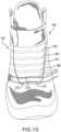
- lace 152 may be configured to pass through various different lacing guides 154 (as shown in phantom lines in FIGS. 10-12 ), which may be further associated with the edges of throat opening 132.
- lacing guides 154 may provide a similar function to traditional eyelets on uppers.
- throat opening 132 may generally constrict so that upper 102 is tightened around a foot.
- lacing guides 154 may comprise a first lacing guide 163, a second lacing guide 165, a third lacing guide 167, a fourth lacing guide 169, a fifth lacing guide 173, and a sixth lacing guide 175 (as shown in FIGS. 10-12 ).
- lacing guides 154 may be used to arrange lace in different configurations. Further, lacing guides 154 may be used to facilitate the tightening or loosening of lace 152 while in various states of tension. For example, in some embodiments, lacing guides 154 may expand as lace 152 is configured in a tensioned or tightened state. With this arrangement, lace 152 is provided more room when tensioning article. Likewise, in some embodiments, lacing guides 154 could compress as lace 152 is configured from a tensioned state to a non-tensioned or loose state. In some embodiments, lace 152, positioned through lacing guides 154, may be arranged in various configurations. Referring to FIGS.
- lace 152 is arranged in parallel configuration on upper. In some other embodiments, lace 152 may be arranged, in a crisscross pattern. In some other embodiments, lace 152, via lacing guides 154 may be arranged in a different configuration.
- lacing guides 154 in this embodiment is only intended to be exemplary and it will be understood that other embodiments are not limited to a particular configuration for lacing guides 154. Furthermore, the particular types of lacing guides 154 illustrated in the embodiments are also exemplary and other embodiments may incorporate any other kinds of lacing guides or similar lacing provisions. In some other embodiments, for example, lace 152 could be inserted through traditional eyelets. Some examples of lace guiding provisions that may be incorporated into the embodiments are disclosed in Cotterman et al., U.S. Patent Application Publication Number 201/0000091 , now U.S. Application Number 13/174,527, filed June 30, 2011 , and titled "Lace Guide”.
- Lace 152 may comprise any type of type of lacing material known in the art.
- Examples of lace that may be used include cables or fibers having a low modulus of elasticity as well as a high tensile strength.
- a lace may comprise a single strand of material, or can comprise multiple strands of material.
- An exemplary material for the lace is SPECTRA TM , manufactured by Honeywell of Morris Township NJ, although other kinds of extended chain, high modulus polyethylene fiber materials can also be used as a lace. Still further exemplary properties of a lace can be found in the Reel Based Lacing Application mentioned above.
- Article 100 may include a plurality of control buttons 182 that are capable of initiating control commands.
- control buttons 182 may allow a user to tighten one or both shoes simultaneously.
- some embodiments could include a "fully tighten” command that would tighten the footwear until a predetermined threshold is achieved (for example, a threshold pressure, winding distance, etc.).
- Article 100 may also include provisions for storing and using preferred tension settings.
- control buttons 182 may be disposed somewhere along upper 102.
- control buttons 182 may be disposed adjacent to opening 130, as shown in FIGS. 1-3 . The operation of control buttons 182 to tighten, or loosen, tensioning system will be explained further in detail below.
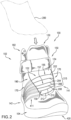
- FIG. 2 shows article 100 is in a fully opened or non-tensioned state just prior to the entry of foot 200.
- lace 152 may be loose enough to allow a user to insert his or her foot into opening 130.
- tensioning system 150 in the open state, a foot can be easily and comfortably removed from footwear 100.
- tensioning system 150 may include any number of laces. In some embodiments, only a single lace may be provided. In other embodiments, multiple laces may be provided.
- lace 152 refers collectively to first lace 155, second lace 157, and third lace 159 that are routed through portions of article 100. Further, the routing of lace 152 may dispose portions of first lace 155, second lace 157, and third lace 159 on a tongue section 134 of upper 102. In one embodiment, these portions on tongue section 134 may include first tensioning portion 202, second tensioning portion 204, third tensioning portion 206, fourth tensioning portion 208, fifth tensioning portion 210, and sixth tensioning portion 212. For clarity, first tensioning portion 202, second tensioning portion 204, third tensioning portion 206, fourth tensioning portion 208, fifth tensioning portion 210, and sixth tensioning portion 212 may be referred to collectively as tensioning set 215.
- Some embodiments may include provisions that provide a custom fit of an article to a wearer's foot.
- custom fit may refer to adjusting specific, localized portions or regions of an upper, as opposed to the entire upper, to comfortably fit the shape and contours of the article to a wearer's foot.
- Provisions include motorized tensioning device 160 (as shown in FIG. 4 ) comprised of components that adjust portions of upper 102.
- provisions may further include control mechanisms such as control buttons 182 allowing an incremental tightening or loosening of lace 152 and in particular, tensioning set 215.
- tensioning system 150 may tighten lace 152 thereby adjusting upper 102 in a variety of ways.
- lace 152 may be characterized as being in a state of non-tension 190, as shown in FIG. 2 .
- a pressure force such as when a wearer inserts a foot and presses down on sole structure 104, activates motorized tensioning device 160.
- the pressure force may result in motorized tensioning device 160 actuating components to draw lace 152 into housing unit 412.
- an incremental tighten command may be sent to motorized tensioning device 160 by pressing control buttons 182. This command causes motorized tensioning device 160 to enter an incremental tighten mode.
- tensioning set 215 may constrict throat opening 132. Further, increased tension of lace 152 will adjust regions of the upper, as shown in FIG. 3 . In some embodiments, during this event lace 152 may be characterized as being in a state of tension 192.
- localized regions may refer to a particular zone, portion, or area of upper.
- localized regions may extend along a lateral axis 191 between medial side 141 and lateral side 143.
- localized region may be spaced apart from opening 135.
- localized regions may be spaced along a longitudinal axis 181 extending between forefoot region 101 and midfoot region 103.
- tensioning set 215 may apply different amounts of downward and inward pressure to the upper 102 as well.
- first lace 155 may include first tensioning portion 202 and second tensioning portion 204 which adjusts a first region 230 of upper 102 during operation.
- First tensioning portion 202 and second tensioning portion may be associated with a first amount of tension that applies a downward and inward pressure to the upper 102.
- second lace 157 may include third tensioning portion 206 and fourth tensioning portion 208 which adjusts a second region 232, which is spaced apart and different from first region 230, of upper 102 during operation.
- third tensioning portion 206 and fourth tensioning portion 208 may be associated with a second amount of tension, which is different to first amount of tension. The second amount of tension will also apply downward and inward pressure to the upper 102.
- this incremental tightening can occur in discrete steps so that each time the wearer interacts with control buttons 182, lace 152 is taken up by a predetermined amount (for example by rotating a spool or a reel member within motorized tensioning device 160 through a predetermined angle). In other cases, this incremental tightening can occur in a continuous manner. In some cases, the speed of tightening can be set so that the system does not overshoot a preferred level of tightness (i.e., the system does not move between not tight enough and overly tight too quickly) while also being large enough to avoid overly long times for fully tightening article 100.
- FIG. 4 schematically illustrates an exemplary placement of motorized tensioning device 160 when attached to footwear 100.
- motorized tensioning device 160 may be disposed in a housing unit 412.
- lace 152 may be routed from motorized tensioning device 160 throughout upper 102 such that lace 152 passes throughinternal channels 411 positioned along sidewall portions 170 (as seen in FIGS 1-4 ).
- internal channels 411 are disposed on sidewall portions 170 on medial side 141 and lateral side 143 of upper 102. Internal channels 411 may guide the lace 152 away from and back towards motorized tensioning device 160. The routing of lace 152 from motorized tensioning device 160 through upper 102 and back towards motorized tensioning device 160 will be explained further in detail below.
- lace 152 may provide distinct advantages.
- a majority of a length of lace 152 may be disposed outside of housing unit 142.
- housing unit 412 may be reduced in size.
- motorized tensioning device 160 may be mounted along a region of sole structure 104. In one embodiment, motorized tensioning device 160 can be mounted on a lower surface 420 (the surface that is facing away from a foot when article 100 is worn by a user) of sole structure 104. In some embodiments, motorized tensioning device 160 can be mounted along midfoot region 103 of sole structure 104. In one embodiment, an external cavity 450 located on lower surface 420 of sole structure 104 may be configured to receive motorized tensioning device 160. In some other embodiments, motorized tensioning device 160 may be mounted on lower surface 420 in other ways known in the art.
- motorized tensioning device 160 may include provisions for receiving portions of lace 152.
- lace 152 may exit internal channels 411 of upper 102 and pass through apertures 156 before entering housing unit 412 of motorized tensioning device 160 as seen in FIG. 5 .
- motorized tensioning device 160 may be removably attached, so that motorized tensioning device 160 can be easily removed by a user and modified (for example, when a lace must be changed).
- motorized lacing device 160 could be fixedly attached to sole structure 104 permanently.
- an external harness (not shown) may be used to mount motorized tensioning device 160 to sole structure 104 at midfoot region 103.
- motorized lacing device 160 can be joined in any manner to lower surface 420, including mechanical attachments, adhesives, and/or molding.
- motorized tensioning device 160 may be configured to automatically apply tension to lace 152 for purposes of tightening and loosening upper 102.
- motorized tensioning device 160 may include provisions for winding lace 152 onto, and unwinding lace 152 from, reel elements internal to motorized tensioning device 160.
- the provisions may include a motor assembly that actuates components for facilitating the winding and unwinding of lace 152 onto reel elements in response to various inputs or controls.
- operating modes may refer to states of the tensioning system itself, as well as to the operating modes of individual subsystems and/or components of the tensioning system.
- Exemplary modes include an "incremental tighten mode", an “incremental loosen mode” and a “fully loosen” mode. The latter two modes may also be referred to as an "incremental release mode” and a “full release mode”.
- incremental tighten mode motorized tightening device 160 may operate in a manner that incrementally (or gradually) tightens, or increases the tension of, lace 152.
- motorized tightening device 160 may operate in a manner that incrementally (or gradually) loosens, or releases tension in, lace 152. As discussed further below, the incremental tighten mode and the incremental loosen mode may tighten and loosen a lace in discrete steps or continuously. In the full release mode, motorized tightening device 160 may operate in a manner so that tension applied to the lace by the system is substantially reduced to a level where the user can easily remove his or her foot from the article. This is in contrast to the incremental release mode, where the system operates to achieve a lower tension for the lace relative to the current tension, but not necessarily to completely remove tension from the laces.
- the full release mode may be utilized to quickly release lace tension so the user can remove the article
- the incremental release mode may be utilized to make minor adjustments to the lace tension as a user searches for the desired amount of tension, thereby providing user with a custom fit.
- the embodiments describe three possible modes of operation (and associated control commands), other operating modes may also be possible.
- some embodiments could incorporated a fully tighten operating mode where motorized tightening device 160 continues to tighten lace 152 until a predetermined tension has been achieved.
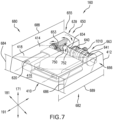
- FIGS. 7 , 8 and 13 illustrate exemplary components of motorized tensioning device 160. For purposes of illustration, some components of motorized tensioning device 160 have been omitted or depicted in isolation from other components.
- housing unit 412 may be shaped so as to optimize the arrangement of components of motorized tensioning device 160.
- the arrangement of components may allow housing unit 412 to have a tapered thickness, relative to a vertical axis, of housing unit 412.
- the arrangement of components in housing 412 may allow housing unit 412 to have a tapered width.
- housing unit 412 may have a tapered vertical profile, as shown in FIG. 7 .
- housing unit 412 may have a first end 680 with a first height 684, relative to vertical axis 171 and an opposite second end 682 with a second height 686, where first height 684 is greater than second height 686.
- first end 680 and second end 682 may be positioned along a longitudinal axis 181.
- first end 680 and second end 682 may be positioned along a lateral axis 191.
- housing unit 412 may also have a tapered width relative to longitudinal axis 181 or lateral axis 191. In other words, the width of housing unit 412 may taper from a first width 688 at first end 680 to second width 689 at second end 682.
- Housing unit 412 may further include an inner housing portion 416 and an outer housing portion 418.
- Outer housing portion 418 may include a base panel 410 as well as an outer cover 414, and generally provides a protective outer covering for components of motorized tensioning device 160.
- Inner housing portion 416 may be shaped and include apertures 490 and cavities 492 to support components of motorized tensioning device 160 (as shown in FIG. 8 ). In some cases portions of inner housing portion 416 function to limit the mobility of some components, as discussed in detail below.
- Motorized tensioning device 160 includes a motor assembly 620.
- motor assembly 620 could include an electric motor.
- motor assembly 620 could comprise any kind of non-electric motor known in the art. Examples of different motors that can be used include, but are not limited to: DC motors (such as permanent-magnet motors, brushed DC motors, brushless DC motors, switched reluctance motors, etc.), AC motors (such as motors with sliding rotors, synchronous electrical motors, asynchronous electrical motors, induction motors, etc.), universal motors, stepper motors, piezoelectric motors, as well as any other kinds of motors known in the art.
- Motor assembly 620 may further include a motor crankshaft 622 that can be used to drive one or more components of motorized tensioning device 160. Provisions for powering motor assembly 620, including various kinds of batteries, are discussed in detail below.
- motorized tensioning device 160 includes provisions for reducing the output speed of, and increasing the torque generated by, motor assembly 620.
- Motorized tensioning device 160 includes one or more gear reduction assemblies and/or gear reduction systems.
- motorized tensioning device 160 may include a single gear reduction assembly.
- motorized tensioning device 160 may include two or more gear reduction assemblies.
- motorized tensioning device 160 includes first gear reduction assembly 630 and second gear reduction assembly 632, which may be collectively referred to as gear reduction system 628.
- First gear reduction assembly 630 may be a gear reduction assembly that is generally aligned with motor assembly 620 and/or crankshaft 622 (also shown in FIG. 13 ).
- second gear reduction assembly 632 may provide additional gear reduction that extends in a generally perpendicular direction to the orientation of crankshaft 622.
- Gear reduction system 628 is mechanically coupled with motor assembly 620.
- first gear reduction assembly 630 may extend along lateral axis 191 of housing unit 412 while second gear reduction assembly 632 may extend along a longitudinal axis 181 of housing unit 412.
- motor assembly 620 can be arranged in parallel with spools and a corresponding reel shaft (as discussed in further detail below). This arrangement may reduce the longitudinal space required to fit all the components of motorized tensioning device 160 within housing unit 412.
- Each gear reduction assembly can comprise one or more gears.
- first gear reduction assembly 630 comprises one or more gears.
- first gear reduction assembly 630 may be driven by crankshaft 622, and include a first gear 634, a second gear 635, and a third gear 636.
- second gear reduction assembly 632 may be configured with an additional stage of gear, including a fourth gear 637.
- fourth gear 637 acts in conjunction with third gear 636, for turning additional components of motorized tensioning device 160, as described in further detail below.
- third gear 636 may comprise a worm and fourth gear 637 may comprise a worm wheel.
- the operation and/or coupling of third gear 636 and fourth gear 637 may be referred to as a worm gear or worm drive 639 (also shown in FIG. 13 ), which will be discussed further below.
- second gear reduction assembly 632 includes one gear. However, other embodiments could use any other number of gears. Likewise, the number of gears comprising first gear reduction assembly 630 may vary in different embodiments. Additionally, in different embodiments, the type of gears used in first gear reduction assembly 630 and/or second gear reduction assembly 632 could vary. In some cases, spur gears may be used.
- gears that may be used include, but are not limited to: helical gears, external gears, internal gears, bevel gears, crown gears, worm gears, non-circular gears, rack and pinion gears, epicyclic gears, planetary gears, harmonic drive gears, cage gears, magnetic gears as well as any other kinds of gears and/or any combinations of various kinds of gears.
- the number, type and arrangement of gears for gear reduction system 628 may be selected to achieve the desired tradeoff between size, torque and speed of the motorized tensioning device 160.
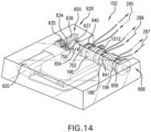
- Motorized tensioning device 160 includes provisions for winding and unwinding portions of a lace. As stated previously, motorized tensioning device 160 includes a first reel member 640 and a second reel member 641. First reel member 640 and second reel member 641 may be referred to collectively as reel members 663. In other embodiments, a third reel member 659 may be present (as shown in FIG. 14 ).
- first lace 155 may have a first end secured to first reel member 640, and second end secured to second reel member 641. In embodiments where there are multiple laces, any combination may be used for securing lace 152 or multiple laces onto reel members 663. Referring to FIGS. 5 and 6 , in one embodiment, first lace 155, second lace 157, and third lace 159 may have one end secured to first reel member 640. Likewise, first lace 155, second lace 157, and third lace 159 may have the opposite end secured to second reel member 641.
- first lace 155 may have both ends attached to first reel member 640, while second lace 157 and/or third lace 159 may have their respective ends attached to second reel member 641 (as shown schematically in FIG. 9 ).
- first lace 155 and second lace 157 may be attached to both first reel member 640 and second reel member 641, whereas third lace 159 may be have its end attached to second reel member 641.
- the pull-in rate 195 meaning the speed of the winding of lace 152 around reel members 663 may be varied.
- Reel members 663 are so dimensioned to further provide a custom fit to the wearer.
- the diameter of reel members 663 may be varied to accommodate pull-in rate 195 of lace 152.
- first reel member 640 has a first diameter 196 larger than second diameter 198 of second reel member 641.
- third diameter 199 may be different than either first diameter 196 or second diameter 198 (as shown in FIG. 14 ).
- the varying diameters when combined with gear reduction system 628, allow for accommodating the different pull-in rates of lace 152 as they are pulled into housing unit 412.
- first lace 155, second lace 157, and third lace 159 from housing unit 412 may also vary the tension of lace 152 and tensioning set 215. By varying the tension, the amount of downward and inward pressure placed on localized regions or zones of upper 102 can be balanced and varied on the wearer's foot.
- first lace 155 may exit housing unit 412 (as shown generally in FIGS. 4 , 5 and 9 ).
- First lace 155 may then extend upwards along a first medial internal channel 430 on a side portion of upper 102, continue through lacing guides 154 positioned on tongue section 134 as first tensioning portion 202 (as seen in FIGS. 2 and 12 ), and then down through a first lateral internal channel 440 on opposite lateral side 143 of upper (as shown generally in FIG. 1 ).
- First lace 155 may then pass through a first loop channel 447 which routes first lace 155 back to housing unit 412 (as shown in FIG 6 and 12 ).
- first lace 155 may be configured to pass upward through second lateral internal channel 442 (as shown in FIG. 1 ), adjacent first lateral internal channel 440, then extend through lacing guides 154 as second tensioning portion 204 (as shown in FIGS 2 and 12 ). Referring to FIG. 4 , first lace 155 will then continue down through second medial internal channel 432 adjacent first medial internal channel 430, and back into housing unit 412 with second end secured to second reel member 641. Likewise, second lace 157, and third lace 159 may be routed in a similar fashion. As discussed earlier, in some other embodiments, third lace 159, for example, may have both ends secured to second reel member 641.
- first lace 155 may be configured to pass through non-adjacent internal channels 411.
- first lace 155 may be configured to pass through third lateral internal channel 444 which is not adjacent to first lateral internal channel 440 (as shown in FIG. 1 ).
- first loop channel 447 may be configured to route first lace 155 from first lateral internal channel 440 to third lateral internal channel 444 with second lateral internal channel 442 disposed between them .
- first lace 155 may continue through lacing guides 154, as third tensioning portion 206, and then routed through third medial internal channel 434 before the second end enters housing unit 412 and is secured to second reel member 641.
- lace 152 may be routed through different internal channels 411 and positioned in lacing guides 154 as different portions of tensioning set 215. With this arrangement, different tensions may be applied to lace 152 and tensioning set 215 in order to vary the amount of pressure on different regions of upper 102 during operation.
- the amount of tension of first tensioning portion 202 proximal to opening 130 may be less than the amount of tension of sixth tensioning portion 212 proximal to forefoot region 101.
- second tensioning portion 204, third tensioning portion 206, fourth tensioning portion 208, and fifth tensioning portion 210 may also have varying degrees of tension.
- the decreased tension of first tensioning portion 202 near the top of the article reduces an amount of pressure placed on the top of a wearer's foot which in turn reduces friction between the wearer's foot and article 100. With this arrangement, a custom fit is provided, with varying pressure throughout upper 102.
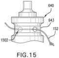
- first reel member 640 may further comprise a first receiving portion 642 for receiving a lace
- second reel member 641 may comprise a second receiving portion 644 for receiving a lace
- first receiving portion 642 may comprise a first lace winding region 646 and a second lace winding region 648, which in some cases can be used to separately wind two ends of a lace
- second receiving portion 644 may comprise a third lace winding region 647 and a fourth lace winding region 649. Since torque output goes down as lace 152 builds up in diameter, using separate winding regions for each lace end may help decrease the diameter of wound lace on reel members 663 and thereby minimize torque output reduction.
- first lace winding region 646 and second lace winding region 648 may be separated by a dividing portion 643, which may include a lace receiving channel 645 for permanently retaining a portion of the lace on first reel member 640 (as shown in FIG. 15 ).
- Lace 152 may be secured to reel members 663 by any method known in the art.
- reel apertures 1502 may be used for inserting lace 152 and the tying ends into a knot. In other cases, different methods may be used.
- first receiving portion 642 may comprise a single lace winding region.
- third lace winding region 647 and fourth lace winding region 649 may be separated by a dividing portion, which may include a lace receiving channel for permanently retaining a portion of the lace on second reel member 641.
- second receiving portion 644 may comprise a single lace winding region.
- Motorized lacing system 160 may include provisions for transferring torque between a first gear reduction assembly 630 and second gear reduction assembly 632. Furthermore, in some embodiments, motorized lacing system 160 may include provisions for transferring torque from second gear reduction assembly 632 (or more generally from gear reduction system 628) to first reel member 640 and/or second reel member 641 in a manner that allows for incremental tightening, incremental loosening and full loosening of a lace. In one embodiment, motorized lacing system 160 may be configured with a torque transmitting system as the primary means for the transmission of torque from worm drive 639 to first reel member 640 and/or second reel member 641 in order to wind (or unwind) lace 152.
- torque transmitting system 650 may further comprise various assemblies and components.
- torque transmitting system 650 may include a first shaft and a second shaft and a rotation control assembly.
- the first shaft is a worm shaft 653, and the second shaft is a reel shaft 654, and the rotation control assembly is in the form of worm drive 639. More specifically, these components operate in a manner that allows for incremental tightening (spool winding), incremental loosening (spool unwinding) as well as full tension release (during which time substantially no torque is transferred from fourth gear 637 to first reel member 640 and second reel member 641).
- Some embodiments can also include a fixed bearing, which may be associated with a first end portion 655 of reel shaft 654.
- reel members 663 may be positioned at different locations of torque transmitting system 650.
- first reel member 640 and second reel member 641 may be positioned adjacent to one another. Further, in some embodiments, first reel member 640 and second reel member 641 may be concentrically mounted to a second end portion 666 of reel shaft 654.
- positioning first reel member 640 adjacent to second reel member 641 on one end of reel shaft 654 may reduce the area needed for housing unit 412.
- other components of motorized tension device 160 may be arranged vertically, or in a stacked configuration, within housing unit. For example, as shown in FIG. 7 , battery 691 and control unit 693 may be stacked vertically.
- motorized tensioning device 160 may include provisions for adjusting the operation of motor assembly 620 according to one or more feedback signals.
- motorized tensioning device 160 may include a limit switch assembly.
- a limit switch assembly may detect current across portions of the system and vary the operation of motor assembly 620 according to the detected current.
- first rotational direction and second rotational direction refer to rotational directions about a longitudinal axis 181 of reel shaft 654 and are generally opposite rotational directions.
- the first rotational direction may refer to the clockwise rotation of a component about longitudinal axis 181, when viewing the component from the vantage point of second end portion 666 of reel shaft 654.
- the second rotational direction may be then be characterized by the counterclockwise rotation of a component about longitudinal axis 181, when viewing the component from the same vantage point.
- motor assembly 620 may begin operating in order to rotate crankshaft 622.
- Crankshaft 622 may turn an input gear (here, first gear 634) of first gear reduction assembly 630, such that the output gear (here, second gear 635) of first gear reduction assembly 630 drives third gear 636.
- second gear 635 and third gear 636 both rotate, which drives fourth gear 637 in first rotational direction 750.
- fourth gear 637 may engage and drive torque transmitting system 650 such that first reel member 640 and second reel member 641 may begin to rotate in first rotational direction 750. This may cause lace 152 to wind onto first receiving portion 642 of first reel member 640 and second receiving portion 644 of second reel member 641.
- motor assembly 620 may operate to rotate crankshaft 622.
- motor assembly 620 and crankshaft 622 turn in an opposite direction of the direction associated with tightening.
- the gear reduction system 628 is then driven such that fourth gear 637 of second gear reduction assembly 632 rotates in second rotational direction 752.
- fourth gear 637 does not directly drive portions of torque transmitting system 650, first reel member 640 and second reel member 641.
- fourth gear 637 in the second rotational direction 752 causes the torque transmitting system 650 to momentarily release first reel member 640 and second reel member 641, allowing first reel member 640 and second reel member 641 to unwind by a predetermined amount after which the torque transmitting system reengages first reel member 640 and second reel member 641 and prevents further unwinding.
- This sequence of releasing and catching first reel member 640 and second reel member 641 occurs over and over as long as fourth gear 637 rotates in second rotational direction 752.
- first reel member 640 and second reel member 641 may rotate more easily in the unwinding direction or second rotational direction 752 about reel shaft 654.
- third gear 636 and fourth gear 637 torque may be transmitted between worm shaft 654 and reel shaft 654.
- Third gear 636 may include an internally threaded cavity that may engage a threading on worm shaft 653.
- Fourth gear 637 may include an internally threaded cavity that may engage a threading on reel shaft 654. It is to be understood that characterizing third gear 636 and/or fourth gear 637 as part of one assembly does not preclude it from being associated with a different assembly.
- motorized tensioning device 160 is activated by a pressure force on sole structure.
- motor assembly 620 may actuate gear reduction system 628. Which in turn will result in worm shaft 653 and affixed third gear 636 to rotate with respect to lateral axis 191.
- Rotating third gear 636 which is intermeshed with fourth gear 637, referred to collectively as worm drive 639, will then drive fourth gear 637 which in turn rotates reel shaft 654.
- first reel member 640 and second reel member 641 are concentrically mounted to the reel shaft 654, the rotation of reel shaft 654 rotates first reel member 640 and second reel member 641 to wind lace 152 upon reel members 663 in response.
- first reel member 640 with lace 152 may have a first pull-in rate 295 while second reel member 641 with lace 152 may have a second pull-in rate 296 different from first pull-in rate 295.
- second reel member 641 with lace 152 may have a second pull-in rate 296 different from first pull-in rate 295.
- third reel member 659 is present, a third pull-in rate 297 is available.
- Different pull-in rates may be affected by various factors to include, but not limited to the routing of lace 152 throughout article 100, different diameter sizes of reel members 663, and gear sizes of gear reduction system 628.
- worm drive 639 has the characteristic of a unidirectional or one-way transmission also referred to as self-locking mechanism.
- one-way transmission refers to the feature that rotation can only be transmitted from third gear 636 to fourth gear 637. Further, the rotation cannot be transmitted from fourth gear 637 to third gear 636. In other words, third gear 636 can only drive fourth gear 637 and not the reverse. With this arrangement, lace 152 cannot be easily loosened (unwind) and will remain at the desired amount of tension.
- the worm drive 639 depicted herein is only intended to be exemplary of a one-way torque transmitting mechanism that may be used to transmit torque to a reel member.
- Other embodiments are not limited to worm-like mechanisms and could include other one-way mechanisms.
- Examples of other one-way mechanisms that could be used include, but are not limited to: roller bearings, sprag clutches, ratcheting wheel and pawl as well as other mechanisms.
- worm shaft 653 may comprise a first end region 673 and a second end region 675.
- first end region 673 may include threading.
- the threading may engage an internally threaded cavity of third gear 636, which may facilitate the relative axial movement of fourth gear 637 along reel shaft 654.
- Worm shaft 653 may also include a second end region 675 that can be associated with second gear 635 in some embodiments.
- an intermediate region 626 of worm shaft 653 may be disposed between first end region 673 and second end region 675. In one embodiment, intermediate region 626 may extend between second gear 635 and third gear 636.
- reel shaft 654 can be configured to receive first reel member 640 and second reel member 641 at second end portion 666 of reel shaft 654 such that reel members 663 are coaxial with reel shaft 654.
- first end portion 655 of reel shaft 654 may be associated with rotation control assembly or worm drive 639.
- reel shaft 654 can be configured to receive first reel member 640 and second reel member 641 at opposite ends of reel shaft 654 such that reel members 663 are coaxial with reel shaft 654.
- alternate methods could be used for coupling a shaft and reel members.
- examples include other kinds of physical interlocking features or including friction increasing features.
- axial compliant friction coupling could be achieved using a wave washer or Belleville washer.
- Embodiments may include a battery and/or control unit configured to power and control motorized tensioning device 160.
- FIGS. 7 and 8 illustrate a schematic view of an embodiment of a battery 691, battery assembly 720 and a control unit 693.
- motorized tensioning device 160, battery 691, battery assembly 720 and control unit 693 are all disposed in housing unit 412, which may function to receive and protect these components.
- Battery 691 is only intended as a schematic representative of one or more types of battery technologies that could be used to power motorized tightening device 160.
- One possibly battery technology that could be used is a lithium polymer battery.
- the battery (or batteries) could be rechargeable or replaceable units packaged as flat, cylindrical, or coin shaped.
- batteries could be single cell or cells in series or parallel.
- Rechargeable batteries could be recharged in place or removed from an article for recharging.
- charging circuitry could be built in and on board.
- charging circuitry could be located in a remote charger.
- inductive charging could be used for charging one or more batteries.
- a charging antenna could be disposed in a sole structure of an article and the article could then be placed on a charging mat to recharge the batteries.
- Additional provisions could be incorporated to maximize battery power and/or otherwise improve use.
- batteries could be used in combination with super caps to handle peak current requirements.
- energy harvesting techniques could be incorporated which utilize the weight of the runner and each step to generate power for charging a battery.
- Control unit 693 is only intended as a schematic representation of one or more control technologies that could be used with motor tensioning device 160.
- motor control there are various approaches to motor control that may be employed to allow speed and direction control.
- a microcontroller unit may be used.
- the microcontroller may use internal interrupt generated timing pulses to create pulse-width modulation (PWM) output.
- PWM pulse-width modulation
- This PWM output is fed to an H-bridge which allows high current PWM pulses to drive the motor both clockwise and counterclockwise with speed control.
- any other methods of motor control known in the art could also be used.
- the tensioning system may include a manual release mechanism.
- tensioning system 150 is equipped with a manual release mechanism 1010.
- manual release mechanism 1010 acts as a safety feature in the event of a loss of battery power. The engagement of manual release mechanism 1010 will unlock first reel member 640 and second reel member 641. Unlocking first reel member 640 and second reel member 641 will allow manually unwinding lace 152 thereby relieving the amount of tension in lace 152 and tension set 215. In some cases, where third reel member 659 is present (as shown in FIG. 14 ), manual release mechanism 1012 will unlock first reel member 640, second reel member 641, and third reel member 659.
Landscapes
- Engineering & Computer Science (AREA)
- Microelectronics & Electronic Packaging (AREA)
- Footwear And Its Accessory, Manufacturing Method And Apparatuses (AREA)
Claims (15)
- Article chaussant (100), comprenant :une tige (102) ;une structure de semelle (104) attachée à la tige (102), la structure de semelle (104) ayant une partie centrale du pied ;un dispositif de tensionnement motorisé (160) attaché de manière fixe à la partie centrale du pied ;le dispositif de tensionnement motorisé (160) comprenant un ensemble moteur couplé à un élément arbre ;le dispositif de tensionnement motorisé (160) comportant un premier élément de bobine (640) et un premier élément de lacet (155) fixé au premier élément de bobine (640) ;dans lequel le premier élément de bobine (640) est monté concentriquement sur l'élément arbre ;dans lequel le dispositif de tensionnement motorisé (160) est activé par une force de pression appliquée à la structure de semelle (104) ;dans lequel le premier élément de lacet (155) s'enroule sur le premier élément de bobine (640) en réponse à une rotation du premier élément de bobine (640) dans une première direction de rotation ; etdans lequel une partie du premier élément de lacet (155) s'étend à travers une première partie localisée de la tige (102) et dans lequel la première partie localisée de la tige (102) est ajustée en réponse à l'enroulement du premier élément de lacet (155) dans la première direction de rotation ;caractérisé en ce que :l'ensemble moteur du dispositif de tensionnement motorisé (160) est couplé à l'élément arbre par un système de démultiplication, et le système de démultiplication fait tourner l'élément arbre et le premier élément de bobine (640) dans la première direction de rotation ;le dispositif de tensionnement motorisé (160) comprend un deuxième élément de bobine (641) et un deuxième élément de lacet (157), et dans lequel le deuxième élément de lacet (157) est fixé au deuxième élément de bobine (641) ; etle premier élément de bobine (640) a un premier diamètre et le deuxième élément de la bobine (641) a un deuxième diamètre différent du premier diamètre.
- Article chaussant (100) selon la revendication 1, dans lequel le deuxième élément de bobine (641) est monté concentriquement sur l'élément arbre, et le deuxième élément de bobine (641) est adjacent au premier élément de bobine (640).
- Article chaussant (100) selon la revendication 2, dans lequel une partie du deuxième élément de lacet (157) s'étend à travers une deuxième partie localisée de la tige (102) et dans lequel la deuxième partie localisée de la tige (102) est ajustée en réponse à l'enroulement du deuxième élément de lacet (157) dans la première direction de rotation.
- Article chaussant (100) selon la revendication 1, dans lequel le dispositif de tensionnement motorisé (160) comprend une unité de logement, l'unité de logement a une première largeur et une deuxième largeur par rapport à un axe latéral, l'axe latéral s'étendant entre un côté médial et un côté latéral, la première largeur est proximale à un côté latéral et la deuxième largeur est proximale à un côté médial ; et dans lequel la première largeur est différente de la deuxième largeur.
- Article chaussant (100) selon la revendication 1, dans lequel le premier élément de bobine (640) et le deuxième élément de bobine (641) sont fixés à une première partie d'extrémité de l'élément arbre et dans lequel le système de démultiplication vient en prise avec une deuxième partie d'extrémité de l'élément arbre.
- Article chaussant (100) selon la revendication 1, dans lequel :le système de démultiplication comprend un premier engrenage engrené avec un deuxième engrenage ;le premier engrenage et le deuxième engrenage sont positionnés à une première partie d'extrémité de l'élément arbre ;le dispositif de tensionnement motorisé (160) comporte un groupe d'éléments de bobines comprenant le premier élément de bobine (640), le deuxième élément de bobine (641) et un troisième élément de bobine configuré pour enrouler des éléments de lacet qui s'étendent à travers la tige (102) ; etle premier élément de bobine (640), le deuxième élément de bobine (641) et le troisième élément de bobine sont montés concentriquement sur une deuxième partie d'extrémité de l'élément arbre.
- Article chaussant (100) selon la revendication 6, dans lequel le troisième élément de bobine a un troisième diamètre qui est différent du premier diamètre et du deuxième diamètre.
- Article chaussant (100) selon la revendication 6, dans lequel le premier élément d'engrenage et le deuxième élément d'engrenage comprennent un entraînement par vis sans fin.
- Article chaussant (100) selon la revendication 6, dans lequel le dispositif de tensionnement motorisé (160) comprend un troisième élément de lacet (159) ;dans lequel le premier élément de lacet (155) a une première extrémité fixée au premier élément de bobine (640) et une deuxième extrémité fixée au premier élément de bobine (640) ;dans lequel le deuxième élément de lacet (157) a une troisième extrémité fixée au deuxième élément de bobine (641) et une quatrième extrémité fixée au troisième élément de bobine ; etdans lequel le troisième élément de lacet (159) a une cinquième extrémité fixée au troisième élément de bobine et une sixième extrémité fixée au troisième élément de bobine.
- Article chaussant (100) selon la revendication 9, dans lequel le premier élément de lacet (155) est associé à une première quantité de tension, le deuxième élément de lacet (157) est associé à une deuxième quantité de tension sur la tige (102), et le troisième élément de lacet (159) est associé à une troisième quantité de tension ; et
dans lequel la première quantité de tension, la deuxième quantité de tension et la troisième quantité de tension sont toutes différentes les unes des autres. - Article chaussant (100) selon la revendication 1, dans lequel le premier élément de lacet (155) a une première extrémité fixée au premier élément de bobine (640) et une deuxième extrémité fixée au premier élément de bobine (640) ;
dans lequel le deuxième élément de lacet (157) a une troisième extrémité fixée au deuxième élément de bobine (641) et une quatrième extrémité fixée au deuxième élément de bobine (641). - Article chaussant (100) selon la revendication 11, dans lequel le premier élément de lacet (155) est configuré pour s'enrouler sur le premier élément de bobine (640) à une première vitesse de traction et dans lequel le deuxième élément de lacet (157) est configuré pour s'enrouler sur le deuxième élément de bobine (641) à une deuxième vitesse de traction qui est différente de la première vitesse de traction.
- Article chaussant (100) selon la revendication 12, dans lequel un premier guide de laçage, un premier canal interne médial, un premier canal interne latéral et un premier canal en boucle acheminent le premier élément de lacet (155) à travers la tige (102).
- Article chaussant (100) selon la revendication 11 ou 12, dans lequel le dispositif de tensionnement motorisé (160) comprend un troisième élément de lacet (159), le troisième élément de lacet (159) ayant une cinquième extrémité fixée au premier élément de bobine (640) et une sixième extrémité fixée au deuxième élément de bobine (641).
- Article chaussant (100) selon la revendication 12, dans lequel le dispositif de tensionnement motorisé (160) comprend une batterie et une unité de commande ; et
la batterie et l'unité de commande sont disposées dans une configuration empilée le long d'un axe vertical à l'intérieur d'une unité de logement, et dans lequel l'axe vertical est perpendiculaire à une surface horizontale de la structure de semelle (104).
Priority Applications (3)
| Application Number | Priority Date | Filing Date | Title |
|---|---|---|---|
| EP23177562.8A EP4275535A3 (fr) | 2015-05-29 | 2016-05-12 | Dispositif de tensionnement motorisé comprenant un système de bobine compact |
| EP22154392.9A EP4011237A1 (fr) | 2015-05-29 | 2016-05-12 | Dispositif de tensionnement motorisé comprenant un système de bobine compact |
| EP22175348.6A EP4070682A1 (fr) | 2015-05-29 | 2016-05-12 | Dispositif de tensionnement motorisé comprenant un système de bobine compact |
Applications Claiming Priority (2)
| Application Number | Priority Date | Filing Date | Title |
|---|---|---|---|
| US201562168049P | 2015-05-29 | 2015-05-29 | |
| PCT/US2016/032048 WO2016195957A1 (fr) | 2015-05-29 | 2016-05-12 | Dispositif de tensionnement motorisé comprenant un système de bobine compact |
Related Child Applications (5)
| Application Number | Title | Priority Date | Filing Date |
|---|---|---|---|
| EP22175348.6A Division EP4070682A1 (fr) | 2015-05-29 | 2016-05-12 | Dispositif de tensionnement motorisé comprenant un système de bobine compact |
| EP22175348.6A Division-Into EP4070682A1 (fr) | 2015-05-29 | 2016-05-12 | Dispositif de tensionnement motorisé comprenant un système de bobine compact |
| EP23177562.8A Division EP4275535A3 (fr) | 2015-05-29 | 2016-05-12 | Dispositif de tensionnement motorisé comprenant un système de bobine compact |
| EP22154392.9A Division EP4011237A1 (fr) | 2015-05-29 | 2016-05-12 | Dispositif de tensionnement motorisé comprenant un système de bobine compact |
| EP22154392.9A Division-Into EP4011237A1 (fr) | 2015-05-29 | 2016-05-12 | Dispositif de tensionnement motorisé comprenant un système de bobine compact |
Publications (2)
| Publication Number | Publication Date |
|---|---|
| EP3302155A1 EP3302155A1 (fr) | 2018-04-11 |
| EP3302155B1 true EP3302155B1 (fr) | 2023-06-07 |
Family
ID=56117964
Family Applications (4)
| Application Number | Title | Priority Date | Filing Date |
|---|---|---|---|
| EP23177562.8A Pending EP4275535A3 (fr) | 2015-05-29 | 2016-05-12 | Dispositif de tensionnement motorisé comprenant un système de bobine compact |
| EP16728437.1A Active EP3302155B1 (fr) | 2015-05-29 | 2016-05-12 | Dispositif de tensionnement motorisé comprenant un système de bobine compact |
| EP22154392.9A Pending EP4011237A1 (fr) | 2015-05-29 | 2016-05-12 | Dispositif de tensionnement motorisé comprenant un système de bobine compact |
| EP22175348.6A Pending EP4070682A1 (fr) | 2015-05-29 | 2016-05-12 | Dispositif de tensionnement motorisé comprenant un système de bobine compact |
Family Applications Before (1)
| Application Number | Title | Priority Date | Filing Date |
|---|---|---|---|
| EP23177562.8A Pending EP4275535A3 (fr) | 2015-05-29 | 2016-05-12 | Dispositif de tensionnement motorisé comprenant un système de bobine compact |
Family Applications After (2)
| Application Number | Title | Priority Date | Filing Date |
|---|---|---|---|
| EP22154392.9A Pending EP4011237A1 (fr) | 2015-05-29 | 2016-05-12 | Dispositif de tensionnement motorisé comprenant un système de bobine compact |
| EP22175348.6A Pending EP4070682A1 (fr) | 2015-05-29 | 2016-05-12 | Dispositif de tensionnement motorisé comprenant un système de bobine compact |
Country Status (6)
| Country | Link |
|---|---|
| US (2) | US11812825B2 (fr) |
| EP (4) | EP4275535A3 (fr) |
| JP (1) | JP6981879B2 (fr) |
| KR (2) | KR20210125112A (fr) |
| CN (2) | CN112956783B (fr) |
| WO (1) | WO2016195957A1 (fr) |
Families Citing this family (36)
| Publication number | Priority date | Publication date | Assignee | Title |
|---|---|---|---|---|
| EP2871994B8 (fr) | 2012-08-31 | 2020-11-04 | NIKE Innovate C.V. | Système de tension motorisé à capteurs |
| US9248040B2 (en) * | 2012-08-31 | 2016-02-02 | Boa Technology Inc. | Motorized tensioning system for medical braces and devices |
| EP4275535A3 (fr) | 2015-05-29 | 2024-02-28 | Nike Innovate C.V. | Dispositif de tensionnement motorisé comprenant un système de bobine compact |
| JP6898860B2 (ja) | 2015-05-29 | 2021-07-07 | ナイキ イノベイト シーブイ | 分割されたスプール・システムを備えた電動式テンショニング・デバイスを含むフットウェアの物品 |
| US11185130B2 (en) | 2015-10-07 | 2021-11-30 | Puma SE | Article of footwear having an automatic lacing system |
| US11033079B2 (en) | 2015-10-07 | 2021-06-15 | Puma SE | Article of footwear having an automatic lacing system |
| PL3358981T3 (pl) * | 2015-10-07 | 2019-12-31 | Puma SE | But, zwłaszcza but sportowy |
| US11103030B2 (en) | 2015-10-07 | 2021-08-31 | Puma SE | Article of footwear having an automatic lacing system |
| WO2017092775A1 (fr) | 2015-12-02 | 2017-06-08 | Puma SE | Procédé pour le laçage d'une chaussure, en particulier d'une chaussure de sport |
| US10390589B2 (en) * | 2016-03-15 | 2019-08-27 | Nike, Inc. | Drive mechanism for automated footwear platform |
| US20180116334A1 (en) | 2016-10-27 | 2018-05-03 | Nike, Inc. | Footwear with mechanical foot-insertion assist |
| WO2018093838A1 (fr) * | 2016-11-15 | 2018-05-24 | Rosalind Franklin University Of Medicine And Science | Dispositif de semelle intérieure à délestage intelligent |
| MX2019005958A (es) | 2016-11-22 | 2019-07-10 | Puma SE | Procedimiento para poner o quitar una prenda de ropa al portador o del portador de la misma o para cerrar, poner, abrir o quitar una pieza de equipaje portada por una persona. |
| JP6882472B2 (ja) * | 2016-11-22 | 2021-06-02 | プーマ エス イーPuma Se | 靴、とりわけ、運動靴を締め付けるための方法、および靴、とりわけ、運動靴 |
| CN109923053B (zh) * | 2016-12-09 | 2021-05-28 | 安达满纳米奇精密宝石有限公司 | 卷取装置 |
| WO2018222807A2 (fr) | 2017-05-31 | 2018-12-06 | Nike, Inc. | Systèmes, dispositifs et techniques de laçage automatique de chaussures |
| KR101864205B1 (ko) * | 2017-06-22 | 2018-06-04 | 신윤익 | 신발끈 조임 장치 |
| JP7108054B2 (ja) * | 2018-06-14 | 2022-07-27 | プーマ エス イー | 靴、特に運動靴 |
| WO2020047450A1 (fr) * | 2018-08-31 | 2020-03-05 | Nike Innovate C.V. | Chaussure à laçage automatique ayant une bobine crantée |
| US11684110B2 (en) * | 2018-08-31 | 2023-06-27 | Nike, Inc. | Autolacing footwear |
| CN112930127A (zh) * | 2018-08-31 | 2021-06-08 | 耐克创新有限合伙公司 | 具有细长线轴的自动系带鞋类 |
| US11819087B2 (en) | 2018-11-30 | 2023-11-21 | Nike, Inc. | Autolacing footwear motor having force-directing supports |
| CN109464230B (zh) * | 2018-12-18 | 2020-12-01 | 南通大学 | 一种适用于下肢骨折病人的保护装置 |
| EP4193867A1 (fr) * | 2018-12-27 | 2023-06-14 | NIKE Innovate C.V. | Système de fermeture pour un article chaussant |
| USD899053S1 (en) | 2019-01-30 | 2020-10-20 | Puma SE | Shoe |
| USD889805S1 (en) | 2019-01-30 | 2020-07-14 | Puma SE | Shoe |
| USD906657S1 (en) | 2019-01-30 | 2021-01-05 | Puma SE | Shoe tensioning device |
| EP3958704B1 (fr) * | 2019-04-23 | 2023-06-07 | Puma Se | Article de chaussures ayant un système de laçage automatique |
| JP2022535328A (ja) * | 2019-04-23 | 2022-08-08 | プーマ エス イー | 自動ひも締めシステムを有する履物具 |
| US11484089B2 (en) | 2019-10-21 | 2022-11-01 | Puma SE | Article of footwear having an automatic lacing system with integrated sound damping |
| EP4103009A4 (fr) | 2020-02-14 | 2024-03-13 | Shift Holding Llc | Bobine de changement de vitesse et procédés associés |
| JP2022064758A (ja) * | 2020-10-14 | 2022-04-26 | 日本電産株式会社 | スプール及びそれを備えたレーシングモジュール |
| JP2022064759A (ja) * | 2020-10-14 | 2022-04-26 | 日本電産株式会社 | スプール及びそれを備えたレーシングモジュール |
| USD1014695S1 (en) | 2021-03-24 | 2024-02-13 | Shift Holding, LLC | Shift reel |
| KR102496743B1 (ko) * | 2021-04-13 | 2023-02-07 | 대한민국 | 보행 재활기능 및 자세교정기능이 겸비된 신발용 인장시스템 및 이를 포함하는 신발 |
| TWI827257B (zh) | 2021-09-14 | 2023-12-21 | 荷蘭商耐克創新有限合夥公司 | 用於形成非織工程設計織物紗線結構的系統與自動捲繞系統 |
Family Cites Families (29)
| Publication number | Priority date | Publication date | Assignee | Title |
|---|---|---|---|---|
| IT1186356B (it) * | 1985-11-04 | 1987-11-26 | Nordica Spa | Scarpone da sci con dispositivo di chiusura e con dispositivo di bloccaggio del piede ad azionamento elettrico |
| CH677586A5 (fr) | 1988-11-09 | 1991-06-14 | Lange Int Sa | |
| US5839210A (en) * | 1992-07-20 | 1998-11-24 | Bernier; Rejeanne M. | Shoe tightening apparatus |
| JPH0681879U (ja) | 1993-04-30 | 1994-11-22 | 株式会社小松製作所 | 装軌車両のトラックフレーム |
| TW329382B (en) | 1994-07-19 | 1998-04-11 | Erejeanne M Bernier | Self-tightening shoe |
| US6289558B1 (en) * | 1997-08-22 | 2001-09-18 | Boa Technology, Inc. | Footwear lacing system |
| DE29817003U1 (de) * | 1998-09-22 | 1999-03-25 | Merlaku Kastriot | High-Tech-Schuh-Verschluß-System |
| JP3682967B2 (ja) | 2003-01-20 | 2005-08-17 | 劉 坤 鐘 | 装着の容易な靴 |
| GB0710404D0 (en) | 2007-05-31 | 2007-07-11 | Ussher Timothy J | Powered shoe tightening with lace cord guiding system |
| US7752774B2 (en) * | 2007-06-05 | 2010-07-13 | Tim James Ussher | Powered shoe tightening with lace cord guiding system |
| US20090109659A1 (en) | 2007-10-30 | 2009-04-30 | Iht Technology, Inc. | Footwear with integrated power system |
| FR2924577B1 (fr) * | 2007-12-07 | 2010-03-12 | Ct Tech Cuir Chaussure Maroqui | Article chaussant a serrage facilite |
| US8046937B2 (en) | 2008-05-02 | 2011-11-01 | Nike, Inc. | Automatic lacing system |
| JP2010014222A (ja) | 2008-07-04 | 2010-01-21 | Nsk Warner Kk | ローラ型ワンウェイクラッチの外輪の加工方法 |
| CN102821635B (zh) | 2010-01-21 | 2015-10-14 | 博技术有限公司 | 用于系带系统的引导装置 |
| JP5925765B2 (ja) | 2010-04-30 | 2016-05-25 | ボア テクノロジー,インコーポレイテッド | 紐締めシステムに使用するためのリール、同リールを作る方法、及び同リールと共に使用されるつめ |
| DE112011102255T5 (de) | 2010-07-01 | 2013-05-16 | Boa Technology, Inc. | Senkelführung |
| US8904673B2 (en) * | 2011-08-18 | 2014-12-09 | Palidium, Inc. | Automated tightening shoe |
| US8935860B2 (en) * | 2011-10-28 | 2015-01-20 | George Torres | Self-tightening shoe |
| US20230301402A9 (en) | 2012-08-31 | 2023-09-28 | Nike, Inc. | Motorized tensioning device with compact spool system |
| EP2871994B8 (fr) * | 2012-08-31 | 2020-11-04 | NIKE Innovate C.V. | Système de tension motorisé à capteurs |
| US9248040B2 (en) * | 2012-08-31 | 2016-02-02 | Boa Technology Inc. | Motorized tensioning system for medical braces and devices |
| US9737115B2 (en) * | 2012-11-06 | 2017-08-22 | Boa Technology Inc. | Devices and methods for adjusting the fit of footwear |
| KR102006027B1 (ko) * | 2012-11-09 | 2019-07-31 | 지이 하이브리드 테크놀로지스, 엘엘씨 | 무선 충전이 가능한 신발 및 이에 사용되는 무선 충전 기기 |
| WO2014093913A1 (fr) * | 2012-12-14 | 2014-06-19 | Vans, Inc. | Systèmes de tension pour article chaussant |
| KR20140140733A (ko) * | 2013-05-30 | 2014-12-10 | 정민우 | 운동화의 끈 자동 풀림 과 조임 방법 및 그 장치 |
| US9609918B2 (en) * | 2013-07-11 | 2017-04-04 | Nike, Inc. | Article with closed instep portion having variable volume |
| EP4275535A3 (fr) | 2015-05-29 | 2024-02-28 | Nike Innovate C.V. | Dispositif de tensionnement motorisé comprenant un système de bobine compact |
| PL3358981T3 (pl) | 2015-10-07 | 2019-12-31 | Puma SE | But, zwłaszcza but sportowy |
-
2016
- 2016-05-12 EP EP23177562.8A patent/EP4275535A3/fr active Pending
- 2016-05-12 CN CN202110335786.2A patent/CN112956783B/zh active Active
- 2016-05-12 EP EP16728437.1A patent/EP3302155B1/fr active Active
- 2016-05-12 JP JP2017561877A patent/JP6981879B2/ja active Active
- 2016-05-12 KR KR1020217031966A patent/KR20210125112A/ko not_active Application Discontinuation
- 2016-05-12 EP EP22154392.9A patent/EP4011237A1/fr active Pending
- 2016-05-12 KR KR1020177037205A patent/KR102595025B1/ko active IP Right Grant
- 2016-05-12 CN CN201680042877.4A patent/CN107847015B/zh active Active
- 2016-05-12 WO PCT/US2016/032048 patent/WO2016195957A1/fr active Application Filing
- 2016-05-12 EP EP22175348.6A patent/EP4070682A1/fr active Pending
- 2016-05-12 US US15/575,863 patent/US11812825B2/en active Active
-
2023
- 2023-05-05 US US18/143,813 patent/US20230270210A1/en active Pending
Also Published As
| Publication number | Publication date |
|---|---|
| EP4275535A3 (fr) | 2024-02-28 |
| EP4275535A2 (fr) | 2023-11-15 |
| EP4011237A1 (fr) | 2022-06-15 |
| CN112956783A (zh) | 2021-06-15 |
| CN112956783B (zh) | 2023-09-05 |
| JP6981879B2 (ja) | 2021-12-17 |
| WO2016195957A1 (fr) | 2016-12-08 |
| US11812825B2 (en) | 2023-11-14 |
| US20230270210A1 (en) | 2023-08-31 |
| CN107847015B (zh) | 2021-04-13 |
| KR102595025B1 (ko) | 2023-10-26 |
| KR20180015169A (ko) | 2018-02-12 |
| CN107847015A (zh) | 2018-03-27 |
| EP3302155A1 (fr) | 2018-04-11 |
| KR20210125112A (ko) | 2021-10-15 |
| US20180125168A1 (en) | 2018-05-10 |
| EP4070682A1 (fr) | 2022-10-12 |
| JP2018516672A (ja) | 2018-06-28 |
Similar Documents
| Publication | Publication Date | Title |
|---|---|---|
| EP3302155B1 (fr) | Dispositif de tensionnement motorisé comprenant un système de bobine compact | |
| US11825912B2 (en) | Article of footwear comprising motorized tensioning device with split spool system | |
| EP3429396B1 (fr) | Système de tension et élément enrouleur pour chaussure | |
| US10660406B2 (en) | Tensioning system and reel member for footwear | |
| US20200281318A1 (en) | Motorized tensioning device with compact spool system |
Legal Events
| Date | Code | Title | Description |
|---|---|---|---|
| STAA | Information on the status of an ep patent application or granted ep patent |
Free format text: STATUS: THE INTERNATIONAL PUBLICATION HAS BEEN MADE |
|
| PUAI | Public reference made under article 153(3) epc to a published international application that has entered the european phase |
Free format text: ORIGINAL CODE: 0009012 |
|
| STAA | Information on the status of an ep patent application or granted ep patent |
Free format text: STATUS: REQUEST FOR EXAMINATION WAS MADE |
|
| 17P | Request for examination filed |
Effective date: 20171220 |
|
| AK | Designated contracting states |
Kind code of ref document: A1 Designated state(s): AL AT BE BG CH CY CZ DE DK EE ES FI FR GB GR HR HU IE IS IT LI LT LU LV MC MK MT NL NO PL PT RO RS SE SI SK SM TR |
|
| AX | Request for extension of the european patent |
Extension state: BA ME |
|
| DAV | Request for validation of the european patent (deleted) | ||
| DAX | Request for extension of the european patent (deleted) | ||
| STAA | Information on the status of an ep patent application or granted ep patent |
Free format text: STATUS: EXAMINATION IS IN PROGRESS |
|
| 17Q | First examination report despatched |
Effective date: 20210528 |
|
| STAA | Information on the status of an ep patent application or granted ep patent |
Free format text: STATUS: EXAMINATION IS IN PROGRESS |
|
| GRAP | Despatch of communication of intention to grant a patent |
Free format text: ORIGINAL CODE: EPIDOSNIGR1 |
|
| STAA | Information on the status of an ep patent application or granted ep patent |
Free format text: STATUS: GRANT OF PATENT IS INTENDED |
|
| INTG | Intention to grant announced |
Effective date: 20221212 |
|
| GRAS | Grant fee paid |
Free format text: ORIGINAL CODE: EPIDOSNIGR3 |
|
| GRAA | (expected) grant |
Free format text: ORIGINAL CODE: 0009210 |
|
| STAA | Information on the status of an ep patent application or granted ep patent |
Free format text: STATUS: THE PATENT HAS BEEN GRANTED |
|
| AK | Designated contracting states |
Kind code of ref document: B1 Designated state(s): AL AT BE BG CH CY CZ DE DK EE ES FI FR GB GR HR HU IE IS IT LI LT LU LV MC MK MT NL NO PL PT RO RS SE SI SK SM TR |
|
| REG | Reference to a national code |
Ref country code: GB Ref legal event code: FG4D |
|
| REG | Reference to a national code |
Ref country code: CH Ref legal event code: EP Ref country code: AT Ref legal event code: REF Ref document number: 1572092 Country of ref document: AT Kind code of ref document: T Effective date: 20230615 |
|
| P01 | Opt-out of the competence of the unified patent court (upc) registered |
Effective date: 20230515 |
|
| REG | Reference to a national code |
Ref country code: DE Ref legal event code: R096 Ref document number: 602016079892 Country of ref document: DE |
|
| REG | Reference to a national code |
Ref country code: LT Ref legal event code: MG9D |
|
| REG | Reference to a national code |
Ref country code: NL Ref legal event code: MP Effective date: 20230607 |
|
| PG25 | Lapsed in a contracting state [announced via postgrant information from national office to epo] |
Ref country code: SE Free format text: LAPSE BECAUSE OF FAILURE TO SUBMIT A TRANSLATION OF THE DESCRIPTION OR TO PAY THE FEE WITHIN THE PRESCRIBED TIME-LIMIT Effective date: 20230607 Ref country code: NO Free format text: LAPSE BECAUSE OF FAILURE TO SUBMIT A TRANSLATION OF THE DESCRIPTION OR TO PAY THE FEE WITHIN THE PRESCRIBED TIME-LIMIT Effective date: 20230907 Ref country code: ES Free format text: LAPSE BECAUSE OF FAILURE TO SUBMIT A TRANSLATION OF THE DESCRIPTION OR TO PAY THE FEE WITHIN THE PRESCRIBED TIME-LIMIT Effective date: 20230607 |
|
| REG | Reference to a national code |
Ref country code: AT Ref legal event code: MK05 Ref document number: 1572092 Country of ref document: AT Kind code of ref document: T Effective date: 20230607 |
|
| PG25 | Lapsed in a contracting state [announced via postgrant information from national office to epo] |
Ref country code: RS Free format text: LAPSE BECAUSE OF FAILURE TO SUBMIT A TRANSLATION OF THE DESCRIPTION OR TO PAY THE FEE WITHIN THE PRESCRIBED TIME-LIMIT Effective date: 20230607 Ref country code: NL Free format text: LAPSE BECAUSE OF FAILURE TO SUBMIT A TRANSLATION OF THE DESCRIPTION OR TO PAY THE FEE WITHIN THE PRESCRIBED TIME-LIMIT Effective date: 20230607 Ref country code: LV Free format text: LAPSE BECAUSE OF FAILURE TO SUBMIT A TRANSLATION OF THE DESCRIPTION OR TO PAY THE FEE WITHIN THE PRESCRIBED TIME-LIMIT Effective date: 20230607 Ref country code: LT Free format text: LAPSE BECAUSE OF FAILURE TO SUBMIT A TRANSLATION OF THE DESCRIPTION OR TO PAY THE FEE WITHIN THE PRESCRIBED TIME-LIMIT Effective date: 20230607 Ref country code: HR Free format text: LAPSE BECAUSE OF FAILURE TO SUBMIT A TRANSLATION OF THE DESCRIPTION OR TO PAY THE FEE WITHIN THE PRESCRIBED TIME-LIMIT Effective date: 20230607 Ref country code: GR Free format text: LAPSE BECAUSE OF FAILURE TO SUBMIT A TRANSLATION OF THE DESCRIPTION OR TO PAY THE FEE WITHIN THE PRESCRIBED TIME-LIMIT Effective date: 20230908 |
|
| PG25 | Lapsed in a contracting state [announced via postgrant information from national office to epo] |
Ref country code: FI Free format text: LAPSE BECAUSE OF FAILURE TO SUBMIT A TRANSLATION OF THE DESCRIPTION OR TO PAY THE FEE WITHIN THE PRESCRIBED TIME-LIMIT Effective date: 20230607 |
|
| PG25 | Lapsed in a contracting state [announced via postgrant information from national office to epo] |
Ref country code: SK Free format text: LAPSE BECAUSE OF FAILURE TO SUBMIT A TRANSLATION OF THE DESCRIPTION OR TO PAY THE FEE WITHIN THE PRESCRIBED TIME-LIMIT Effective date: 20230607 |
|
| PG25 | Lapsed in a contracting state [announced via postgrant information from national office to epo] |
Ref country code: IS Free format text: LAPSE BECAUSE OF FAILURE TO SUBMIT A TRANSLATION OF THE DESCRIPTION OR TO PAY THE FEE WITHIN THE PRESCRIBED TIME-LIMIT Effective date: 20231007 |
|
| PG25 | Lapsed in a contracting state [announced via postgrant information from national office to epo] |
Ref country code: SM Free format text: LAPSE BECAUSE OF FAILURE TO SUBMIT A TRANSLATION OF THE DESCRIPTION OR TO PAY THE FEE WITHIN THE PRESCRIBED TIME-LIMIT Effective date: 20230607 Ref country code: SK Free format text: LAPSE BECAUSE OF FAILURE TO SUBMIT A TRANSLATION OF THE DESCRIPTION OR TO PAY THE FEE WITHIN THE PRESCRIBED TIME-LIMIT Effective date: 20230607 Ref country code: RO Free format text: LAPSE BECAUSE OF FAILURE TO SUBMIT A TRANSLATION OF THE DESCRIPTION OR TO PAY THE FEE WITHIN THE PRESCRIBED TIME-LIMIT Effective date: 20230607 Ref country code: PT Free format text: LAPSE BECAUSE OF FAILURE TO SUBMIT A TRANSLATION OF THE DESCRIPTION OR TO PAY THE FEE WITHIN THE PRESCRIBED TIME-LIMIT Effective date: 20231009 Ref country code: IS Free format text: LAPSE BECAUSE OF FAILURE TO SUBMIT A TRANSLATION OF THE DESCRIPTION OR TO PAY THE FEE WITHIN THE PRESCRIBED TIME-LIMIT Effective date: 20231007 Ref country code: EE Free format text: LAPSE BECAUSE OF FAILURE TO SUBMIT A TRANSLATION OF THE DESCRIPTION OR TO PAY THE FEE WITHIN THE PRESCRIBED TIME-LIMIT Effective date: 20230607 Ref country code: CZ Free format text: LAPSE BECAUSE OF FAILURE TO SUBMIT A TRANSLATION OF THE DESCRIPTION OR TO PAY THE FEE WITHIN THE PRESCRIBED TIME-LIMIT Effective date: 20230607 Ref country code: AT Free format text: LAPSE BECAUSE OF FAILURE TO SUBMIT A TRANSLATION OF THE DESCRIPTION OR TO PAY THE FEE WITHIN THE PRESCRIBED TIME-LIMIT Effective date: 20230607 |
|
| PG25 | Lapsed in a contracting state [announced via postgrant information from national office to epo] |
Ref country code: PL Free format text: LAPSE BECAUSE OF FAILURE TO SUBMIT A TRANSLATION OF THE DESCRIPTION OR TO PAY THE FEE WITHIN THE PRESCRIBED TIME-LIMIT Effective date: 20230607 |
|
| REG | Reference to a national code |
Ref country code: DE Ref legal event code: R097 Ref document number: 602016079892 Country of ref document: DE |
|
| PLBE | No opposition filed within time limit |
Free format text: ORIGINAL CODE: 0009261 |
|
| STAA | Information on the status of an ep patent application or granted ep patent |
Free format text: STATUS: NO OPPOSITION FILED WITHIN TIME LIMIT |
|
| PG25 | Lapsed in a contracting state [announced via postgrant information from national office to epo] |
Ref country code: DK Free format text: LAPSE BECAUSE OF FAILURE TO SUBMIT A TRANSLATION OF THE DESCRIPTION OR TO PAY THE FEE WITHIN THE PRESCRIBED TIME-LIMIT Effective date: 20230607 |
|
| PGFP | Annual fee paid to national office [announced via postgrant information from national office to epo] |
Ref country code: GB Payment date: 20240321 Year of fee payment: 9 |
|
| PG25 | Lapsed in a contracting state [announced via postgrant information from national office to epo] |
Ref country code: SI Free format text: LAPSE BECAUSE OF FAILURE TO SUBMIT A TRANSLATION OF THE DESCRIPTION OR TO PAY THE FEE WITHIN THE PRESCRIBED TIME-LIMIT Effective date: 20230607 |
|
| 26N | No opposition filed |
Effective date: 20240308 |