EP3298580B1 - Komponentenhandhabungsanordnung und verfahren zur anpassung einer komponentenhandhabungsanordnung - Google Patents
Komponentenhandhabungsanordnung und verfahren zur anpassung einer komponentenhandhabungsanordnung Download PDFInfo
- Publication number
- EP3298580B1 EP3298580B1 EP16720902.2A EP16720902A EP3298580B1 EP 3298580 B1 EP3298580 B1 EP 3298580B1 EP 16720902 A EP16720902 A EP 16720902A EP 3298580 B1 EP3298580 B1 EP 3298580B1
- Authority
- EP
- European Patent Office
- Prior art keywords
- image
- station
- centre
- nest
- reference element
- Prior art date
- Legal status (The legal status is an assumption and is not a legal conclusion. Google has not performed a legal analysis and makes no representation as to the accuracy of the status listed.)
- Not-in-force
Links
Images


Classifications
-
- G—PHYSICS
- G06—COMPUTING OR CALCULATING; COUNTING
- G06T—IMAGE DATA PROCESSING OR GENERATION, IN GENERAL
- G06T7/00—Image analysis
- G06T7/70—Determining position or orientation of objects or cameras
-
- G—PHYSICS
- G06—COMPUTING OR CALCULATING; COUNTING
- G06T—IMAGE DATA PROCESSING OR GENERATION, IN GENERAL
- G06T7/00—Image analysis
- G06T7/0002—Inspection of images, e.g. flaw detection
- G06T7/0004—Industrial image inspection
- G06T7/001—Industrial image inspection using an image reference approach
-
- H—ELECTRICITY
- H04—ELECTRIC COMMUNICATION TECHNIQUE
- H04N—PICTORIAL COMMUNICATION, e.g. TELEVISION
- H04N23/00—Cameras or camera modules comprising electronic image sensors; Control thereof
- H04N23/56—Cameras or camera modules comprising electronic image sensors; Control thereof provided with illuminating means
-
- H—ELECTRICITY
- H05—ELECTRIC TECHNIQUES NOT OTHERWISE PROVIDED FOR
- H05K—PRINTED CIRCUITS; CASINGS OR CONSTRUCTIONAL DETAILS OF ELECTRIC APPARATUS; MANUFACTURE OF ASSEMBLAGES OF ELECTRICAL COMPONENTS
- H05K13/00—Apparatus or processes specially adapted for manufacturing or adjusting assemblages of electric components
- H05K13/04—Mounting of components, e.g. of leadless components
-
- G—PHYSICS
- G06—COMPUTING OR CALCULATING; COUNTING
- G06T—IMAGE DATA PROCESSING OR GENERATION, IN GENERAL
- G06T2207/00—Indexing scheme for image analysis or image enhancement
- G06T2207/30—Subject of image; Context of image processing
- G06T2207/30108—Industrial image inspection
- G06T2207/30164—Workpiece; Machine component
-
- G—PHYSICS
- G06—COMPUTING OR CALCULATING; COUNTING
- G06T—IMAGE DATA PROCESSING OR GENERATION, IN GENERAL
- G06T2207/00—Indexing scheme for image analysis or image enhancement
- G06T2207/30—Subject of image; Context of image processing
- G06T2207/30204—Marker
-
- G—PHYSICS
- G06—COMPUTING OR CALCULATING; COUNTING
- G06T—IMAGE DATA PROCESSING OR GENERATION, IN GENERAL
- G06T7/00—Image analysis
- G06T7/70—Determining position or orientation of objects or cameras
- G06T7/73—Determining position or orientation of objects or cameras using feature-based methods
-
- H—ELECTRICITY
- H01—ELECTRIC ELEMENTS
- H01J—ELECTRIC DISCHARGE TUBES OR DISCHARGE LAMPS
- H01J2237/00—Discharge tubes exposing object to beam, e.g. for analysis treatment, etching, imaging
- H01J2237/26—Electron or ion microscopes
- H01J2237/28—Scanning microscopes
- H01J2237/2813—Scanning microscopes characterised by the application
- H01J2237/2817—Pattern inspection
-
- H—ELECTRICITY
- H01—ELECTRIC ELEMENTS
- H01J—ELECTRIC DISCHARGE TUBES OR DISCHARGE LAMPS
- H01J2237/00—Discharge tubes exposing object to beam, e.g. for analysis treatment, etching, imaging
- H01J2237/26—Electron or ion microscopes
- H01J2237/282—Determination of microscope properties
- H01J2237/2826—Calibration
-
- H—ELECTRICITY
- H01—ELECTRIC ELEMENTS
- H01J—ELECTRIC DISCHARGE TUBES OR DISCHARGE LAMPS
- H01J2237/00—Discharge tubes exposing object to beam, e.g. for analysis treatment, etching, imaging
- H01J2237/30—Electron or ion beam tubes for processing objects
- H01J2237/304—Controlling tubes
- H01J2237/30433—System calibration
- H01J2237/30438—Registration
Definitions
- the present invention concerns a component handling assembly and a method for adjusting a component handling assembly which involves the use of a vision system to determine a reference position at a station which comprises a reference element, and then using the determined reference position to adjust subsequent stations of the component handling assembly.
- Component handling assemblies usually comprises a rotatable turret which comprises a plurality of component handling heads each of which can hold a component.
- Beneath turret is typically located a plurality of stations each of which can process or test a component in some way. The turret rotates to move the components between the stations and the component handling heads operate to pick and place components from/into the respective stations.
- WO2011076507 discloses a wafer handler comprising: a wafer loading station for loading a wafer mounted on a tack film ; a tensioner for tensioning the tacky film; a picking module (66) for successively picking a plurality of devices from said wafer; a vision system with one or several cameras for capturing a first image of said wafer or of portions of said wafer, said first image comprising a plurality of devices, wherein said vision system is arranged for determining from said first image the individual position of a plurality of devices, and wherein the wafer handle further comprises an additional camera positioned proximate to said picking module and arranged for capturing an second image of a device to be picked, wherein the second image is used for fine adjustment of the wafer so that the device to be picked is centered under the picking module.
- US2010033706 discloses a method for adjusting an arrangement of coordinates in an imaging area of an imaging component in a substrate imaging plane in a substrate position detection apparatus that detects a position of a substrate in accordance with an image taken of a circumferential portion of the substrate by the imaging component, the apparatus being arranged near a rotatable susceptor on which the substrate is placed and a substrate transferring apparatus prepared separately from the susceptor and configured to horizontally drive a supporting pin for transferring the substrate to and/or from the susceptor.
- This method includes supporting at a predetermined height above the susceptor by the supporting pin a mark-equipped wafer with a mark arranged corresponding to the circumferential portion of the substrate, bringing the mark into the imaging area, detecting the mark at plural points while horizontally moving the mark in one direction within the imaging area by a predetermined distance by horizontally driving the supporting pin, and calibrating an axis direction of the coordinates in accordance with a direction in which the plural points are arranged;; and maintaining the mark-equipped wafer with a height adjustment jig at the predetermined height above the susceptor, bringing the mark into the imaging area, detecting the mark at plural points while moving the mark within the imaging area by a predetermined angle by rotating the susceptor, and calibrating an origin position of the coordinates in accordance with a rotation center obtained in accordance with the plural points.
- the camera is located between consecutive component handling heads on the turret.
- the step of rotating the turret so that the camera on the turret is in a position where it can capture a second image of nest of a second station may comprise the step of rotating the turret a distance which is half the distance between consecutive component handling heads on the turret.
- the method comprises the steps of, for each of a plurality of stations which each comprise a nest:
- the second image is an image frame in a live video of the second station, and preferably said step of superimposing a marker on the second image comprises superimposing a marker on each of the image frames in the live video at the same position as the position of the centre of the reference element in the first image.
- the first and second images have the same field of view.
- the step of adjusting the second station until the position in the second image of the centre of the nest of the second station is aligned with the marker may comprise the step of using an x-y table to move the nest of the second station so that the centre of the nest of the second station is aligned with the marker.
- the second station is adjusted automatically until the position in the second image of the centre of the nest of the second station is aligned with the marker;
- the second station may comprise a processor which can operate an x-y table to move the nest of the second station so that the centre of the nest of the second station is aligned with the marker.
- the method may further comprise the step of determining the distance between the marker superimposed on the second image and the position in the second image of the centre of the nest of the second station, to estimate a positioning error of the second station.
- the plate member may comprises a plurality of groups of holes, the holes of each group having equal dimensions, the dimensions of the holes differing between groups, and the step of identifying the position in the first image of the centre of the reference element may further comprise, selecting from the plurality of groups of holes, a group of holes on which to perform said geometrical calculation.
- the step of identifying the position in the second image of the centre of the nest of the second station may comprise, performing grey scale analysis of the second image.
- the step of identifying the position in the second image of the centre of the nest of the second station may comprise the steps of, providing the grey level of each pixel in the second image; identifying, based on the grey levels of the pixels, the perimeter of the nest in the second image; performing a geometrical calculation to determine a point which is at the centre of the identified perimeter, wherein the determined point defines the centre of the nest.
- the processor could be configured to perform and/or initiate the performance of any one or more of the above-mentioned method steps.
- the processor may be configured to perform or initiate the performance of grey scale image analysis to identify the location of the holes of the reference element in the first image and/or to identify the location of the centre of the nest in the second image.
- the processor is further configured to operate an x-y table on which the nest of the second station is supported, so as to move the nest of the second station so that the centre of the nest of the second station is aligned with the marker.
- the camera is preferably located on the turret between consecutive component handling heads.
- the processor may be further configured to, initiate the camera to capture a third image of a reference element located at a first station; identify the position in the third image of the centre of the reference element; superimpose a marker on the third image at the same position as the position of the centre of the reference element in the first image, determine if the camera has become displaced during the period between when the first image captured and when the third image was captured based on whether the superimposed marker is aligned with the position in the third image of the centre of the reference element.
- the processor which is further configured to repeat steps (a)-(f) mentioned above if the superimposed marker is not aligned with the position in the third image of the centre of the reference element.
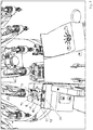
- Figure 1a shows a perspective view of a component handling assembly 1 according to an embodiment of the present invention.
- the component handling assembly 1 comprises a rotatable turret 2 which is selectively operable to rotate about a rotation axis 6.
- the rotatable turret 2 comprises a plurality of component handling heads 3 each of which can hold a component preferably by vacuum.
- the plurality of component handling heads 3 are equally spaced around the rotation axis 6.
- a plurality of stations 4 are located beneath successive component handling heads 3; in Figure 1a only three stations 4 are illustrated however it will be understood that the component handling assembly 1 may comprise any number of stations 4. At least some of the stations 4 comprise a nest 5 on which a component can be supported.
- Figure 1b provides a magnified view of some of the component handling heads 3 and of some of the plurality of stations 4 in the assembly 1 of Figure 1a ; a nest 5 is provided on one of the stations 4.
- the turret 2 can rotate to transport components, which are held by the plurality of component handling heads 3, between the plurality of stations 4.
- the plurality of stations 4 include a first station 4a which is defined by a multifunctional bin 4a.
- a reference element 8 is further provided, and is arranged to rest on the multifunctional bin 4a.
- the reference element 8 is arranged so that it abuts a fixed set of pins 13 (such as dowel pins) which are provided on a surface 14 of the multifunctional bin 4a.
- the fixed set of pins 13 provide a reference position for the reference element 8, allowing the reference element 8 to be always placed in the same position on the multifunctional bin 4a.
- the multifunctional bin 4a has a predefined fixed location; the location of the multifunctional bin 4a remains constant during the performance of all the method steps described hereafter.
- the surface 14 is perpendicular to the rotation axis 6 of the turret 2.
- the reference element 8 is arranged so that it overlays an input of the multifunctional bin 4a (the input is an opening through which components can be passed into the bin; in the figure the input is not visible as it is covered by the reference element 8) .
- the reference element 8 comprises a plate member 11 having a plurality of holes 9 defined therein, wherein the holes 9 are configured such that there is a point 10 which is between the plurality of holes 9 which is equidistance from each of the plurality of holes 9; the point 10 defines the centre of the reference element 8.
- the plate member 11 comprises a plurality of groups 12a-e of holes; specifically the plate member 11 comprises five groups 12a-e of three holes.
- the group 12a comprises holes 9a-c; the group 12b comprises holes 9d-f; the group 12c comprises holes 9g-i; the group 12d comprises holes 9j-l; the group 12e comprises holes 9m-o.
- Each of the holes in a particular group 12a-e have equal dimensions, but the dimensions of the holes differ between groups.
- the point 10 is located equidistance from the three holes of any group 12a-e.
- the plurality of stations 4 further include a plurality of other stations 4; in this example the plurality of stations 4 further include second and third stations 4b,c at which a component can be processed and/or tested. It will be understood that any number of stations 4 may be provided, for example between 3 and 20 stations 4 may be provided, and the stations 4 may be configured to perform any suitable processing and/or testing of a component.
- the third station 4c comprises a nest 5 on which a component can be supported.
- the third station 4c is positioned such that its nest 5 is centred under a component handling head 3 on the turret 2; consequently the nest 5 will also be centred under successive component handling heads 3 on the turret 2 as the turret 2 rotates since the component handling heads 3 are equally spaced around the rotation axis 6 of the turret 2.
- each of those stations are positioned such that their respective nests 5 are centred under a respective component handling head 3 on the turret 2; in such a case the their respective nests 5 will also be centred under successive component handling heads 3 on the turret 2 as the turret 2 rotates since the component handling heads 3 are equally spaced around the rotation axis 6 of the turret 2.
- the component handling assembly 1 comprises a camera 7 which is located on the rotatable turret 2. Specifically the camera 7 is located on the turret 2 between two neighbouring component handling heads 3. The camera is positioned such that it can capture an image of a station 4 located beneath the turret, when the turret 2 is moved to a position whereby the camera is positioned above said station 4.
- the component handling assembly 1 further comprises a mirror assembly 30 which comprises one or more mirrors which are arranged to direct the field of view of the camera to be beneath the turret, so that the camera 7 can be used to capture images of the stations 4.
- the camera 7 is arranged to be parallel to a plane of the turret 2;
- the mirror assembly 30 comprises a mirror arranged to deflect light, which is reflected by the reference element 8 and/or the station 4 below, into the lens of the camera 7 (in this particular example the mirror is arranged at 45° with respect to the plane of the reference element 8 so that light which is reflected by the reference element 8 and/or the station 4 below, is deflected by the mirror into the lens of the camera 7) ; consequently the camera 7 can capture an image of the reference element 8 and/or station 4.
- the camera 7 could be arranged on the turret 2 so that light which is reflected by the reference element 8 and/or the station 4 below is received directly into the lens of the camera 7; thus eliminating the need for a mirror to deflect light into the lens of the camera.
- the camera 7 is a USB camera however it will be understood that any type of camera may be used.
- the user may move the position of the third station 4c until the centre of the nest 5 of the third station 4c in the second image is aligned with the marker.
- the processor 18 may initiate the automatic movement of the position of the third station 4c until the centre of the nest 5 of the third station 4c in the second image is aligned with the marker; for example the nest of the third station 4c may be provided on an x-y table and the processor 18 may initiate the movement of the x-y table so that the centre of the nest 5 of the third station 4c in the second image is aligned with the marker.
- the nest 5 of the third station 4c in the second image is aligned with the marker then the nest 5 of the third station 4c will be centred under a respective component handling head 3 of the turret 2.
- the component handling assembly comprises a plurality of other stations 4 each of which comprises a nest 5; then the processor 18 is configured to perform the above-mentioned steps for each of those other stations 4 so that the respective nests 5 of each of the other stations 4 are centred under a respective component handling head 3 of the turret 2.
- the processor 18 is further configured to:
- the component handling assembly 1 can be used to perform a method for adjusting a component handling assembly according to an embodiment of the present invention.
- the method for adjusting a component handling assembly comprises the steps of,
- the method could be applied to any number of station 4 which are provided in the assembly 1.
- the assembly 1 were to comprise twenty stations 4, in addition to the multifunctional bin 4a, each of which comprising a nest 5, then the steps (a)-(g) can be applied to each of those twenty stations 4 so as to align the nests 5 of the stations 4 with a respective component handling head 3 on the turret 2.
- the first and second images have the same field of view.
- the camera 7 is configured to have a fixed field of view, thus the first and second images will have the same field of view.
- the focus of the camera 7 is adjustable so that the field of view can be changed, and the method will then include a step of checking that the field of view of the camera is set to a predefined level prior to capturing the first image and second images; for example the method may include a step of checking that the field of view of the camera is set to a predefined level prior to capturing the first image; if the field of view of the camera is not at the predefined level then adjusting the camera focus until the field of view of the camera is set to a predefined level; then capturing the first image; and then, prior to capturing the second image, checking that the field of view of the camera 7 is equal to the field of view which the camera had when taking the first image.
- the second image is captured. If the field of views are equal then the second image is captured. If the field of view of the camera 7 is not equal to the field of view which the camera had when taking the first image, then the first image must be recaptured (the turret is rotated back to allow the camera to recapture the first image), and prior to capturing the second image, checking that the field of view of the camera 7 is equal to the field of view which the camera 7 had when taking the recaptured first image.
- the second image is not captured until the field of view of the camera 7 is equal to the field of view which the camera had when taking the first image; thus the steps of recapturing the first image and checking, prior to capturing the second image, that the field of view of the camera 7 is equal to the field of view which the camera had when taking the recaptured first image are repeated until the field of views are the same.
- the camera focus is adjusted until the field of view of the camera is set to be equal to the field of view which the camera had when taking the first image (i.e. is set to said predefined level).
- the camera 7 is configured to provide live video streaming of the nest 5 of the third station 4c.
- the second image may be an image frame of a video, for example the second image may be an image frame of live video.
- camera may provide live video of the third station 4c which shows the nest 5 of the third station 4c; the marker may be superimposed on all image frames of the live video; the user may adjust the third station 4c until the position of the centre of the nest 5 of the third station 4c in the image frames of the live video is aligned with the marker.
- the second image has the same field of view as the first image. For example each of the image frames in the live video will have the same field of view as the first image.
- FIG. 1a-7 An exemplary embodiment of the method will now be described making reference to Figure 1a-7 .
- the reference element 8 which is mechanically independent of the multifunctional bin 4a, is positioned on the surface 14 of the bin 4a so that it abuts a fixed set of pins 13 and overlays an input of the multifunctional bin 4a.
- Figure 1b first image of the reference element 8 located on the multifunctional bin 4a, is captured using a camera 7 which is located on the rotatable turret 2; the features illustrated in Figure 1b have already been described above.
- the turret is moved so that the camera 4 is positioned directly above the multifunctional bin 4a, and more specifically aligned above the reference element 8 which abuts the pins 13.
- the resolution may be such that only groups of holes 12d and 12e are visible on the first image, in which case the user could only select between groups of holes 12d and 12e to be used to calculate the location in the first image 20 of the centre 10 of the reference element 8.
- the group of holes 12a which consists of holes 9a-c, are selected to be used to calculate the location in the first image 20 of the centre 10 of the reference element 8.
- the position of the holes 9a-c in the first image 20 is then identified. It will be understood that it is the position of the holes in the selected group which is identified. This can be achieved by means of performing grey scale analysis such as, providing the grey level of each pixel in the first image 20 and then identifying the location of the holes 9a-c based on the grey levels of the pixels.
- grey scale analysis such as, providing the grey level of each pixel in the first image 20 and then identifying the location of the holes 9a-c based on the grey levels of the pixels.
- the "black" pixels in the grey scale of the first image represent the areas of the holes 9a-c and "white" pixels in the grey scale of the image will represent the other areas of the reference element 8 in the first image 20. Therefore the position of the holes 9a-c in the first image 20 can be identified by identifying the "black" pixels in the grey scale representation of the first image 20.
- the method preferably involves defining some minimum threshold grey level threshold below which a pixel is considered to be “white” and a maximum threshold grey level threshold above which a pixel is considered to be “black”.
- the position of the holes 9a-c in the first image is identified by finding the areas in the grey scale representation of the first image 20 where there is adjacent "white” and "black” pixels; these areas will represent the border of the holes 9a-c.
- the areas of the first image 20 where there is a large change i.e. above a predefined threshold e.g.
- the location of the holes 9a-c can be identified by identifying the regions in the grey scale representation of the first image 20 where the change in grey scale level between adjacent pixels is above a predefined threshold.
- the position of the holes 9a-c in the first image may be identified by identifying consecutive pixels in which difference between in the grey values between the consecutive pixels is least 30GV (black to white scale goes from 0 to 256 GV (grey values)); these adjacent pixels can be recognized as depicting the a border of the holes 9a-c.
- An image analysis tool may be used to aid in the location of the holes 9a-c; for example tools which look for specific patterns (e.g. straight line, ellipse, curves or circle) in the grey scale values of the pixels.
- image analysis tool which is configured to locate circular patterns in the grey scale values of the pixels; in other words the image analysis tool can locate a circular pattern formed by a series of pairs of adjacent pixels whose grey value differs by at least 30GV; by locating such a pattern the border of a hole 9a-c can be located. It is further possible to select pixels which are to be excluded from consideration by the image analysis tool.
- the image analysis tool can further use some predefined parameters like radius of the holes 9a-c, diameter of the holes 9a-c, centre of gravity etc. to help locate the position in the first image of the holes 9a-c.
- any other suitable image analysis can be used to identify the location of the holes 9a-c in the first image 20; the invention is not limited to using a grey scale analysis.
- the position of the centre 10 of the reference element 8 in the first image 20 may then be determined; this can be done by determining the position of the centre of the identified holes 9a-c using the previously identified location of the holes 9a-c in the first image 20 and predetermined known parameters such as diameter, radius and distances between the holes 9a-c in the physical reference element 8. Then performing a geometrical calculation using the position of the centre of the identified holes 9a-c and predetermined known parameters to determine the location in the first image 20 of the centre 10 of the reference element 8.
- FIG. 1 shows the locations in the first image 20 of the centre 10 of the reference element 8 , and their respective locations marked with respective circular markers 21a-c each of which align with the borders of a respective hole 9a-e.
- a geometrical calculation is performed to locate a point which is between the circular markers 21a-c and equidistance from each circular marker 21a-c; this point corresponds to a point which is between the plurality of holes 9a-c and is equidistance from each of the plurality of holes 9a-c; this point also corresponds to the location in the first image 20 of the centre 10 of the reference element 8.
- a frame of reference in the first image 20 is defined and x-coordinates ((X1, X2, X3), wherein X1 is the x-coordinate of the centre of the circular marker 21a, X2 is the x-coordinate of the centre of the circular marker 21b, X3 is the x-coordinate of the centre of the circular marker 21c) and y-coordinates ((Y1, Y2, Y3), wherein Y1 is the y-coordinate of the centre of the circular marker 21a, Y2 is the y-coordinate of the centre of the circular marker 21b, Y3 is the y-coordinate of the centre of the circular marker 21c) for each of the circular markers 21a-c in the first image 20 with respect to this frame of reference is identified.
- Figure 3 illustrates the first image 20 after the geometrical calculation has been performed to locate a point which is between the circular markers 21a-c and equidistance from each circular marker 21a-c.
- the calculated point which corresponds to the location in the first image 20 of the centre 10 of the reference element 8, is marked with a first "x" marker 31.
- the turret 2 is then rotated to a position where the camera 7 on the turret 2 can capture a second image of a nest of another station.
- the turret 2 is rotated to a position where the camera 7 on the turret 2 is in a position where it can capture a second image of the nest 5 of the third station 4c.
- the step of rotating the turret 2 to a position where the camera 7 on the turret 2 is in a position where it can capture a second image of nest 5 of a third station 4c involves rotating the turret 2 to a position where the camera 7 is aligned above the nest 5 of the third station 4c. Since the camera 7 is located between consecutive components handling heads 3 of the turret 2 the turret 2 is rotated through angle of rotation which is equal to one-and-half times the angle between the consecutive component handling heads 3 of the turret 2.
- the second station 4b does not include a nest 5; however it should be understood that typically the second station 4b will also include a nest 5, in which case turret 2 would be rotated to a position where the camera 7 on the turret 2 can capture a second image of a nest of the second station, and the method of the present invention would be performed on the second station 4b, before performing the method of the present invention on the third station 4c.
- the step of rotating the turret 2 to a position where the camera 7 on the turret 2 is in a position where it can capture a second image of nest of a second station 4b which is adjacent to the multifunctional bin 4a involves moving the rotating the turret 2 to a position where the camera 7 is aligned above the nest of a second station 4b.
- the turret 2 Since the camera 7 is located between consecutive components handling heads 3 of the turret 2 the turret 2 would thus be rotated through angle of rotation which is equal to half the angle between the consecutive component handling heads 3 of the turret 2; after the method of the present invention would be performed on the second station 4b the turret 2 would again be rotated through angle of rotation which is equal to half the angle between the consecutive component handling heads 3 so that the camera 7 on the turret 2 is in a position where it can capture a second image of the nest 5 of the third station 4c.
- FIG. 5a & 5b illustrate a second image 50 of the third station 4c.
- the camera 7 is configured to provide live video streaming of the nest 5 of the third station 4c.
- the second image 50 which is shown in Figures 5a and 5b is thus an image frame of live video streaming.
- the second image 50 is then processed to identifying the position in the second image 50 of the centre 51 of the nest 5 of the third station 4c. Any suitable image analysis and/or geometrical calculations can be performed to identify the position in the second image 50 of the centre 51 of the nest 5 of the third station 4c.
- the centre 51 of the nest 5 of the third station 4c is determined by providing the grey level of each pixel in the second image 50; identifying a border/outer perimeter 41 of the nest 5 in the second image 50 based on the grey levels of the pixels (e.g.
- the second image 50 is processed in a similar fashion to the first image 20 so as to determine the location of the centre 51 of the nest 5;so it will be understood that any of the steps described above with respect to processing the first image 20 may equally be applied to process the second image 50.
- the second image 50 is represented in grey scale; in the grey scale representation of the second image 50 the nest 5 will appear as "black” pixels in the grey scale of the second image and the rest of the third station will appear as "white” (and/or grey) pixels.
- the method preferably involve defining some maximum threshold grey level threshold above which a pixel is considered to be “black”.
- the areas in the grey scale representation of the second image 50 where there is adjacent "white” and “black” pixels are then identified; these areas represent the border/outer perimeter 41 of the nest 5. (In another embodiment areas in the grey scale representation of the second image 50 where the change in grey scale level between adjacent pixels is above a predefined threshold is identified.)
- the nest 5 is a quadrilateral shaped.
- a Least Mean Square fitting method (LMS) is performed to find the square/rectangle which best fits to the identified areas (i.e. which best fits to the border/outer perimeter).
- LMS Least Mean Square fitting method
- the nest 5 may be any other suitable shape and the appropriate mean square fitting method (LMS) is performed depending on the shape of the nest 5 to be fitted.
- a frame of reference in the second image 50 is defined; and x-coordinates and y-coordinates for the position of the nest 5 in the second image 50 with respect to the defined frame of reference.
- the frame of reference define in the second image 50 is identical to the frame of reference which was defined in the first image 20.
- the position in the second image 50 of the centre of the nest 5 is determined using suitable geometrical calculations (for example, if the least mean square method determines that the shape of the nest 5 is a square and the x & y-coordinates of the corners of the nest, in the frame of reference, are determined to be at (0,0),(0,1),(1,1),(1,0) then the centre of the nest 5 can be geometrically calculated to be at x & y-coordinates (0.5,0.5).
- the first "x" marker 31 is then superimposed on the second image 50 at the same position as the position of the centre 10 of the reference element 8 in the first image.
- the second image 50 is an image frame of a live video stream of the nest 5 of the third station 4c; the first "x" marker 31 is thus superimposed on all image frames of the live video stream.
- the second image has the same field of view as the first image this allows the first "x" marker 31 to be superimposed on the second image 50 at the same position as the position of the centre 10 of the reference element 8 in the first image.
- the distance 'd' between the first "x" marker 31 and second "x” marker 52 is determined to estimate a positioning error of the third station 4c and/or the position error of the nest 5 of the third station 4c.
- the first "x" marker 31 is illustrated being thicker than the second "x” marker 52 so that both markers can be distinguished; in practice the markers 31,52 may have different colours to allow them to be distinguished.
- the position of the third station 4c and/or the position of the nest 5 of the third station 4c is moved until the position in the second "x" marker 52 is aligned with the first "x" marker 31 in the second image 50.
- the position of the third station 4c and/or the position of the nest 5 of the third station 4c is moved the location in the second image 50 of the centre 51 of the nest 5 is calculated in real time so that the position of the second "x" marker 52 in the second image 50 follows the position of the centre 51 of the nest 5.
- the moving of the position of the third station 4c and/or moving the position of the nest 5 of the third station 4c may be done manually and/or automatically.
- a user may manually adjust the position of the third station 4c and/or may manually adjust the position of the nest 5 of the third station 4c; and/or a means for automatically adjusting the position of the third station 4c and/or the position of the nest 5 of the third station 4c may be used (such as an x-y table for example).
- the method would comprises the step of using an x-y table to move the nest 5 of the third station 4c and/or to move the third station 4c as a whole, so that the centre of the nest 5 of the third station 4c is aligned with the marker.
- Figure 5b shows the second image 50 after the third station 4c and/or the nest 5 of the third station 4c has been moved so that the position of the second "x" marker 52 is aligned with the first "x" marker 31.
- the nest 5 of third station 4c will be aligned directly under a respective component handling head 3 on the turret 2; and as the turret 2 rotates the nest 5 of the third station 4c will also be aligned directly under successive component handling head 3 on the turret 2.
- the turret is rotated to the position which it had when the camera 7 captured the first image.
- the camera 7 is then operated to capture a third image of the reference element 8 located on the multifunctional bin 4a.
- the position in the third image of the centre point 10 of the reference element 8 is identified using the same steps that were used to identify the position in the first image of the centre point 10 of the reference element 8.
- Figure 6 shows an example of a third image 60 in which the position of the centre point 10 of the reference element 8 in the third image has been identified and marked with a third "x" marker 61 .
- the position in the third image 60 of third "x" marker 61 is compared with the position in the first image 20 of first "x” marker 31, so as to determine if the camera 7 has become displaced during the period between when the first image captured and when the third image was captured.
- the first "x" marker 31 may be superimposed on the third image 60 at the same position as the position of the centre 10 of the reference element 8 in the first image; if the first and third "x" markers 31,61 fail to align when the first "x” marker 31 is superimposed on the third image 60 then this indicates that the camera 7 has become displaced during the period between when the first image 20 was captured and when the third image was captured.
- Figure 6 shows the first "x" marker 31 superimposed on the third image 60 at the same position as the position of the centre 10 of the reference element 8 in the first image 20; the first and third "x" markers 31,61 fail to align indicating that the camera 7 has become displaced during the period between when the first image 20 was captured and when the third image 60 was captured.
- the third image 60 and first image 20 may be overlapped and if the first and third "x" markers 31,61 fail to align when the third and first images 60,20 are overlapped then this indicates that the camera 7 has become displaced during the period between when the first image captured and when the third image was captured.
- the positions of the stations 4 in the assembly will need to be adjusted once again; thus if the comparison of the first and third images indicates that the camera has become displaced during the period between when the first image captured and when the third image was captured, then the above-mentioned steps are repeating on each of the stations 4 of the assembly 1 so that the position of the nest 5 of each of the stations 4 are aligned once again.
- the component handling heads 3 on the turret are each configured such that they can extend from the turret 2 along an axis 23 towards a respective station 4.
- the method of adjusting the assembly 1 may further comprise the optional step of adjusting one or more of the component handling heads 3 on the turret 2:
- the method of the present invention may further comprise the optional step of adjusting the position of a component handling head 3 on the turret 2 so that the axis 23 along which the component handling head 3 can extend intersects the centre point 10 of the reference element 8.
- the position of the component handling heard 3 on the turret 2 may be manually adjusted or may be automatically adjusted using suitable adjusting means.
- the method may further optionally comprise calibrating the movement of the component handling head 3 on the turret 2, as is also illustrated in Figure 7 .
- this calibration of the movement of the component handling head 3 on the turret 2 involves, holding a rubber component 76 which has a predefined dimension using the component handling head 3 to be calibrated; operating a light emitter 74 which is located on the multifunctional bin 4a so that it emits a light beam 77 which is received by a light receiver 78 on the multifunctional bin 4a, wherein the light beam 77 is arranged to be at a predefined height "h" above a surface 14 of the multifunctional bin 4a.
- the component handling head 3 is advanced towards the surface 14 of the multifunctional bin 4a only until the rubber component 76 intersects the light beam 77 to block the light beam 77 from passing from the light emitter 74 to the light receiver 78; setting the component handling assembly 1 so that the component handling head 3 is prevented from advancing beyond the position where the rubber component 76 which it held intersected the light beam 77.
Landscapes
- Engineering & Computer Science (AREA)
- Computer Vision & Pattern Recognition (AREA)
- Physics & Mathematics (AREA)
- General Physics & Mathematics (AREA)
- Theoretical Computer Science (AREA)
- Manufacturing & Machinery (AREA)
- Microelectronics & Electronic Packaging (AREA)
- Quality & Reliability (AREA)
- Multimedia (AREA)
- Signal Processing (AREA)
- Length Measuring Devices By Optical Means (AREA)
- Automatic Assembly (AREA)
Claims (15)
- Verfahren zum Anpassen einer Komponentenhandhabungsanordnung (1), wobei die Komponentenhandhabungsanordnung (1) umfasst: eine Vielzahl von Stationen (4), von denen mindestens einige ein Nest (5) aufweisen, das eine Komponente aufnehmen kann, und einen drehbaren Revolverkopf (2) mit einer Vielzahl von Komponentenhandhabungsköpfen (3), und worin der Revolverkopf (2) drehbar ist, um Komponenten zwischen der Vielzahl von Stationen zu transportieren, wobei das Verfahren die folgenden Schritte umfasst:Erfassen eines ersten Bildes eines sich an einer ersten Station (4a) befindlichen Referenzelements (8) unter Verwendung einer sich auf dem drehbaren Revolverkopf (2) befindlichen Kamera (7);Identifizieren im ersten Bild der Position der Mitte (10) des Referenzelements (8);Drehen des Revolverkopfes (2) derart, dass die Kamera (7) auf dem Revolverkopf (2) sich in einer Position befindet, in der sie ein zweites Bild des Nestes (5) einer zweiten Station (4c) aufnehmen kann;Erfassen eines zweiten Bildes des Nestes (5) der zweiten Station (4c) unter Verwendung der besagten Kamera (7);Identifizieren im zweiten Bild der Position der Mitte des Nestes (5) der zweiten Station (4c);dadurch gekennzeichnet, dass das Verfahren zudem die nachfolgenden Schritte umfasst:Überlagern einer Markierung (31) auf das zweite Bild an derselben Position, wie die Position der Mitte (10) des Referenzelements (8) im ersten Bild;Einstellen der zweiten Station (4c), bis die Position der Mitte des Nestes (5) der zweiten Station im zweiten Bild mit der Markierung (31) ausgerichtet ist.
- Verfahren gemäss Anspruch 1, worin das zweite Bild ein Einzelbild in einem Live-Video der zweiten Station ist, und worin der besagte Schritt des Überlagerns einer Markierung auf dem zweiten Bild das Überlagern einer Markierung auf jedem der Einzelbilder im Live-Video an derselben Position wie die Position der Mitte des Referenzelements im ersten Bild umfasst.
- Verfahren gemäss Anspruch 1 oder 2, worin das erste und das zweite Bild dasselbe Sichtfeld haben.
- Verfahren gemäss einem beliebigen der vorhergehenden Ansprüche, worin der Schritt des Einstellens der zweiten Station, bis dass die Position im zweiten Bild der Mitte des Nestes der zweiten Station mit der Markierung ausgerichtet ist, den Schritt des Benutzens einer XY-Tabelle umfasst, um das Nest der zweiten Station so zu verschieben, dass die Mitte des Nestes der zweiten Station mit der Markierung ausgerichtet ist.
- Verfahren gemäss einem beliebigen der vorhergehenden Ansprüche, worin das Verfahren zudem folgenden Schritt umfasst: Bestimmen des Abstandes zwischen der auf dem zweiten Bild überlagerten Markierung und der Position der Mitte des Nestes der zweiten Station im zweiten Bild, um einen Positionierungsfehler der zweiten Station abzuschätzen.
- Verfahren gemäss einem beliebigen der vorhergehenden Ansprüche, worin das Referenzelement ein Plattenteil mit einer Vielzahl von darin definierten Löchern aufweist, und worin der Schritt des Identifizierens der Position im ersten Bild der Mitte des Referenzelements folgendes umfasst:Identifizieren der Position im ersten Bild der Vielzahl von Löchern;Durchführen einer geometrischen Berechnung, um einen Punkt im ersten Bild zu lokalisieren, der sich in Äquidistanz von jedem der Vielzahl von Löchern befindet, wobei der besagte lokalisierte Punkt die Mitte des Referenzelements definiert.
- Verfahren gemäss einem beliebigen der vorhergehenden Ansprüche, worin das Plattenteil eine Vielzahl von Löchergruppen aufweist, wobei die Löcher jeder Gruppe dieselben Abmessungen haben, wobei sich die Abmessungen der Löcher zwischen den Gruppen unterscheiden, und worin der Schritt des Identifizierens der Position im ersten Bild der Mitte des Bezugselements zudem umfasst:
das Auswählen einer Gruppe von Löchern aus der Vielzahl von Löchergruppen, an welcher die besagte geometrische Berechnung durchgeführt wird. - Verfahren gemäss einem beliebigen der vorhergehenden Ansprüche, worin der Schritt des Identifizierens der Position der zweiten Mitte des Nestes der zweiten Station im zweiten Bild die folgenden Schritte umfasst:Bereitstellen der Graustufe jedes Pixels im zweiten Bild;Identifizieren des Umfangs des Nestes im zweiten Bild basierend auf den Graustufen der Pixel;Durchführen einer geometrischen Berechnung, um einen Punkt zu bestimmen, der sich in der Mitte des identifizierten Umfangs befindet, worin der bestimmte Punkt die Mitte des Nestes definiert.
- Verfahren gemäss einem beliebigen der vorhergehenden Ansprüche, worin die erste Station einen festen Satz von Stiften umfasst, die eine vordefinierte Position für das Referenzelement definieren, und worin das Verfahren zudem den folgenden Schritt umfasst:
Positionieren eines Referenzelements an der ersten Station, so dass das Referenzelement einem festen Satz von Stiften der ersten Station anliegt, so dass sich das Referenzelement in der besagten vordefinierten Position befindet. - Verfahren gemäss einem beliebigen der vorhergehenden Ansprüche, worin das Verfahren zudem die folgenden Schritte umfasst:Erfassen eines dritten Bildes eines sich an einer ersten Station befindlichen Referenzelements unter Verwendung der Kamera, die sich auf dem drehbaren Revolver befindet;Identifizieren der Position der Mitte des Referenzelements im dritten Bild;Überlagerung eines Markers auf dem dritten Bild an derselben Position wie die Position des Mittelpunkts des Referenzelements im ersten Bild;Bestimmen, ob die Kamera während des Zeitraums zwischen dem Zeitpunkt des Erfassens des ersten Bildes und dem Zeitpunkt des Erfassens des dritten Bildes verschoben wurde, darauf basierend, ob die überlagerte Markierung mit der Position der Mitte des Referenzelements im dritten Bild ausgerichtet ist.
- Verfahren nach einem beliebigen der vorhergehenden Ansprüche, worin der Komponentenhandhabungskopf so konfiguriert ist, dass er sich entlang einer Achse vom Revolverkopf erstrecken kann, und worin das Verfahren zudem den folgenden Schritt umfasst:
Einstellen der Position eines Komponentenhandhabungskopfes, so dass die Achse, entlang der sich der Komponentenhandhabungskopf erstrecken kann, die Mitte des Referenzelements schneidet. - Verfahren gemäss einem beliebigen der vorhergehenden Ansprüche, wobei das Verfahren zudem den Schritt des Kalibrierens eines Komponentenhandhabungskopfes auf dem Revolverkopf umfasst,
indem eine Komponente mit einer vordefinierten Abmessung unter Verwendung des zu kalibrierenden Komponentenhandhabungskopfes gehalten wird;
indem ein Lichtsender an einer Station unterhalb des Komponentenhandhabungskopfes betrieben wird, so dass er einen Lichtstrahl aussendet, der von einem Lichtempfänger an der Station empfangen wird, worin der Lichtstrahl so angelegt ist, dass er sich in einer vordefinierten Höhe oberhalb einer Oberfläche der Station befindet;
indem der Komponentenhandhabungskopfs nur soweit in Richtung einer Station bewegt wird, bis das die Komponente den Lichtstrahl schneidet, um den Lichtstrahl daran zu hindern, vom Lichtsender zum Lichtempfänger zu gelangen;
indem der Komponentenhandhabungsanordnung so eingestellt wird, dass verhindert wird, dass sich der Komponentenhandhabungskopf über die Position hinausbewegt, an welcher die Komponente, die er hielt, den Lichtstrahl kreuzte. - Komponentenhandhabungsanordnung (1), umfassend:eine Vielzahl von Stationen (4), von denen mindestens einige ein Nest (5) aufweisen, das eine Komponente aufnehmen kann, worin die Vielzahl von Stationen eine erste Station (4a) beinhaltet, die ein Referenzelement (8) umfasst, und eine zweite Station, die ein Nest (5) umfasst;einen drehbaren Revolverkopf (2) mit einer Vielzahl von Komponentenhandhabungsköpfen (3), worin der Revolverkopf (2) drehbar ist, um Komponenten zwischen der Vielzahl von Stationen (4) zu transportieren;eine Kamera (7), die sich auf dem drehbaren Revolverkopf befindet; wobei die Komponentenhandhabungsanordnung umfasst:einen Prozessor (18), der konfiguriert ist um,(a) die Kamera (7) zu veranlassen, ein erstes Bild eines sich an einer ersten Station (4a) befindliches Referenzelements (8) zu erfassen;(b) die Position im ersten Bild der Mitte (10) des Referenzelements (8) zu identifizieren;(c) das Drehen des Revolverkopfs (2) zu veranlassen, so dass die Kamera (7) auf dem Revolverkopf (2) sich in einer Position befindet, in der sie ein zweites Bild des Nestes (5) einer zweiten Station (4c) aufnehmen kann;(d) die Kamera zu veranlassen, ein zweites Bild des Nestes der zweiten Station (4c) aufzunehmen;(e) die Position im zweiten Bild der zweiten Station der Mitte des Nestes (5) der zweiten Station (4c) zu identifizieren;dadurch gekennzeichnet, dass der Prozessor zudem konfiguriert ist zum:
(f) Überlagern einer Markierung (31) auf das zweite Bild an derselben Position wie die Position der Mitte des Referenzelements (8) im ersten Bild, so dass der Benutzer feststellen kann, wie die zweite Station eingestellt werden soll, damit die Position im zweiten Bild der Mitte des Nestes (5) der zweiten Station (4c) auf die Markierung (31) ausgerichtet ist. - Komponentenhandhabungsanordnung gemäss Anspruch 13, worin die Kamera sich auf dem Revolverkopf zwischen aufeinanderfolgenden Komponentenhandhabungsköpfen befindet.
- Komponentenhandhabungsanordnung gemäss Anspruch 13 oder 14, worin das Referenzelement ein Plattenteil mit einer Vielzahl von darin definierten Löchern aufweist.
Applications Claiming Priority (2)
| Application Number | Priority Date | Filing Date | Title |
|---|---|---|---|
| CH6932015 | 2015-05-19 | ||
| PCT/IB2016/052059 WO2016185298A1 (en) | 2015-05-19 | 2016-04-12 | Component handling assembly and method of adjusting a component handling assembly |
Publications (2)
| Publication Number | Publication Date |
|---|---|
| EP3298580A1 EP3298580A1 (de) | 2018-03-28 |
| EP3298580B1 true EP3298580B1 (de) | 2019-04-03 |
Family
ID=57319533
Family Applications (1)
| Application Number | Title | Priority Date | Filing Date |
|---|---|---|---|
| EP16720902.2A Not-in-force EP3298580B1 (de) | 2015-05-19 | 2016-04-12 | Komponentenhandhabungsanordnung und verfahren zur anpassung einer komponentenhandhabungsanordnung |
Country Status (9)
| Country | Link |
|---|---|
| US (1) | US10157475B2 (de) |
| EP (1) | EP3298580B1 (de) |
| KR (1) | KR20180008383A (de) |
| CN (1) | CN107408309A (de) |
| MY (1) | MY182508A (de) |
| PH (1) | PH12017501468A1 (de) |
| SG (1) | SG11201705744WA (de) |
| TW (1) | TWI680362B (de) |
| WO (1) | WO2016185298A1 (de) |
Families Citing this family (5)
| Publication number | Priority date | Publication date | Assignee | Title |
|---|---|---|---|---|
| WO2018162956A1 (en) * | 2017-03-09 | 2018-09-13 | Ismeca Semiconductor Holding Sa | A testing assembly and method for testing electrical components |
| KR20190134801A (ko) * | 2017-05-31 | 2019-12-04 | 가부시키가이샤 후지킨 | 반도체 제조 장치의 관리 시스템, 방법 및 컴퓨터 프로그램 |
| CN108897597B (zh) * | 2018-07-20 | 2021-07-13 | 广州方硅信息技术有限公司 | 指导配置直播模板的方法和装置 |
| DE102020118407A1 (de) * | 2020-07-13 | 2022-01-13 | Soft2Tec Gmbh | Vorrichtung und Verfahren zur Lage- und Positionserkennung von Markierungen im dreidimensionalen Raum |
| KR102889444B1 (ko) * | 2023-12-26 | 2025-11-21 | (주)피엠피 | 터릿형 피커의 공압제어장치 |
Family Cites Families (13)
| Publication number | Priority date | Publication date | Assignee | Title |
|---|---|---|---|---|
| US4721228A (en) * | 1985-04-03 | 1988-01-26 | Itt Corporation | Apparatus for dispensing elongated small mechanical parts |
| US5157734A (en) | 1989-12-19 | 1992-10-20 | Industrial Technology Research Institute | Method and apparatus for picking and placing a surface mounted device with the aid of machine vision |
| KR20020077515A (ko) * | 2000-03-02 | 2002-10-11 | 가부시키가이샤 니콘 | 위치계측장치 및 노광장치 |
| AU2001286946A1 (en) * | 2000-09-01 | 2002-03-13 | Asyst Technologies, Inc. | Edge grip aligner with buffering capabilities |
| JP2004353549A (ja) * | 2003-05-29 | 2004-12-16 | Sango Co Ltd | ハニカム構造体内蔵流体処理装置の製造方法 |
| WO2004109793A1 (ja) | 2003-05-30 | 2004-12-16 | Ebara Corporation | 試料検査装置及び方法並びに該試料検査装置及び方法を用いたデバイス製造方法 |
| CN100420109C (zh) * | 2003-09-22 | 2008-09-17 | 株式会社村田制作所 | 用于安装发光元件的方法和设备 |
| JP4656440B2 (ja) * | 2007-02-13 | 2011-03-23 | 東京エレクトロン株式会社 | 基板位置検出装置及びその撮像手段位置調整方法 |
| JP5193294B2 (ja) * | 2008-05-30 | 2013-05-08 | 三星ダイヤモンド工業株式会社 | レーザ加工装置およびレーザ加工方法 |
| EP2339611B1 (de) * | 2009-12-23 | 2015-11-11 | ISMECA Semiconductor Holding SA | Plättchen-Manipulator mit einem Sichtsystem |
| CN104508504A (zh) * | 2012-11-05 | 2015-04-08 | 伊斯梅卡半导体控股公司 | 用于对部件的性能进行测试的组件 |
| CN103231087A (zh) * | 2013-05-17 | 2013-08-07 | 无锡新宏泰电器科技股份有限公司 | 薄壁零件自定心装置 |
| WO2014209226A1 (en) * | 2013-06-07 | 2014-12-31 | Asti Holdings Limited | Systems and methods for automatically verifying correct die removal from film frames |
-
2016
- 2016-04-12 US US15/545,262 patent/US10157475B2/en not_active Expired - Fee Related
- 2016-04-12 EP EP16720902.2A patent/EP3298580B1/de not_active Not-in-force
- 2016-04-12 WO PCT/IB2016/052059 patent/WO2016185298A1/en not_active Ceased
- 2016-04-12 MY MYPI2017702620A patent/MY182508A/en unknown
- 2016-04-12 CN CN201680012915.1A patent/CN107408309A/zh active Pending
- 2016-04-12 KR KR1020177023896A patent/KR20180008383A/ko not_active Withdrawn
- 2016-04-12 SG SG11201705744WA patent/SG11201705744WA/en unknown
- 2016-04-22 TW TW105112680A patent/TWI680362B/zh not_active IP Right Cessation
-
2017
- 2017-08-14 PH PH12017501468A patent/PH12017501468A1/en unknown
Non-Patent Citations (1)
| Title |
|---|
| None * |
Also Published As
| Publication number | Publication date |
|---|---|
| US20180253859A1 (en) | 2018-09-06 |
| KR20180008383A (ko) | 2018-01-24 |
| CN107408309A (zh) | 2017-11-28 |
| SG11201705744WA (en) | 2017-08-30 |
| TW201702778A (zh) | 2017-01-16 |
| WO2016185298A1 (en) | 2016-11-24 |
| TWI680362B (zh) | 2019-12-21 |
| MY182508A (en) | 2021-01-25 |
| EP3298580A1 (de) | 2018-03-28 |
| US10157475B2 (en) | 2018-12-18 |
| PH12017501468A1 (en) | 2018-01-15 |
Similar Documents
| Publication | Publication Date | Title |
|---|---|---|
| KR100719210B1 (ko) | 웨이퍼용 검사장치 | |
| US5528359A (en) | Image scanning apparatus and method | |
| US20190132560A1 (en) | Method for calibrating image capturing sensor consisting of at least one sensor camera, using time coded patterned target | |
| US10187636B2 (en) | Active lens alignment system | |
| US10157475B2 (en) | Component handling assembly and method of adjusting a component handling assembly | |
| EP2631868B1 (de) | Bildverarbeitungsvorrichtung und Bildverarbeitungsverfahren | |
| JP4946668B2 (ja) | 基板位置検出装置及び基板位置検出方法 | |
| CN101183655A (zh) | 图形对位方法、图形检查装置及图形检查系统 | |
| US20160125583A1 (en) | Systems and methods for automatically verifying correct die removal from film frames | |
| US20110010122A1 (en) | Calibrating separately located cameras with a double sided visible calibration target for ic device testing handlers | |
| EP3264181B1 (de) | Vorausrichtungsverfahren für substrat | |
| JP2013534312A (ja) | ウェハのソーマークの三次元検査のための装置および方法 | |
| KR101963110B1 (ko) | 불투명한 재료에 의해 실질적으로 커버되는 웨이퍼를 절단하기 위한 장치 및 방법 | |
| TW201019056A (en) | Testing method for alignment mark and device thereof | |
| US20050172695A1 (en) | Method of calibrating a detector and calibration sphere for the same | |
| TWI635786B (zh) | Substrate position detecting device | |
| TWI504859B (zh) | 拍攝並拼接物件影像的方法 | |
| CN104253070B (zh) | 使用成像设备以调整半导体元件的处理设备的装置和方法 | |
| JP3893191B2 (ja) | 計測用撮像装置の校正値測定方法 | |
| EP2535923B1 (de) | Erkennungsverfahren und erkennungsvorrichtung | |
| JP2008014700A (ja) | ワークの検査方法及びワーク検査装置 | |
| KR102740889B1 (ko) | Ats 보정방법 | |
| WO2018146887A1 (ja) | 外観検査装置 | |
| JP2006514350A (ja) | 光学式文字認識装置及び方法 | |
| CN113533356A (zh) | 晶粒阵列缺陷检测方法、装置、设备及可读存储介质 |
Legal Events
| Date | Code | Title | Description |
|---|---|---|---|
| STAA | Information on the status of an ep patent application or granted ep patent |
Free format text: STATUS: THE INTERNATIONAL PUBLICATION HAS BEEN MADE |
|
| PUAI | Public reference made under article 153(3) epc to a published international application that has entered the european phase |
Free format text: ORIGINAL CODE: 0009012 |
|
| STAA | Information on the status of an ep patent application or granted ep patent |
Free format text: STATUS: REQUEST FOR EXAMINATION WAS MADE |
|
| 17P | Request for examination filed |
Effective date: 20171019 |
|
| AK | Designated contracting states |
Kind code of ref document: A1 Designated state(s): AL AT BE BG CH CY CZ DE DK EE ES FI FR GB GR HR HU IE IS IT LI LT LU LV MC MK MT NL NO PL PT RO RS SE SI SK SM TR |
|
| AX | Request for extension of the european patent |
Extension state: BA ME |
|
| DAV | Request for validation of the european patent (deleted) | ||
| DAX | Request for extension of the european patent (deleted) | ||
| REG | Reference to a national code |
Ref country code: DE Ref legal event code: R079 Ref document number: 602016011912 Country of ref document: DE Free format text: PREVIOUS MAIN CLASS: G06T0007000000 Ipc: G06T0007700000 |
|
| GRAP | Despatch of communication of intention to grant a patent |
Free format text: ORIGINAL CODE: EPIDOSNIGR1 |
|
| STAA | Information on the status of an ep patent application or granted ep patent |
Free format text: STATUS: GRANT OF PATENT IS INTENDED |
|
| RIC1 | Information provided on ipc code assigned before grant |
Ipc: H05K 13/04 20060101ALI20181009BHEP Ipc: H04N 5/225 20060101ALI20181009BHEP Ipc: G06T 7/70 20170101AFI20181009BHEP Ipc: G06T 7/00 20170101ALI20181009BHEP |
|
| INTG | Intention to grant announced |
Effective date: 20181030 |
|
| GRAJ | Information related to disapproval of communication of intention to grant by the applicant or resumption of examination proceedings by the epo deleted |
Free format text: ORIGINAL CODE: EPIDOSDIGR1 |
|
| STAA | Information on the status of an ep patent application or granted ep patent |
Free format text: STATUS: REQUEST FOR EXAMINATION WAS MADE |
|
| GRAS | Grant fee paid |
Free format text: ORIGINAL CODE: EPIDOSNIGR3 |
|
| STAA | Information on the status of an ep patent application or granted ep patent |
Free format text: STATUS: GRANT OF PATENT IS INTENDED |
|
| GRAP | Despatch of communication of intention to grant a patent |
Free format text: ORIGINAL CODE: EPIDOSNIGR1 |
|
| INTC | Intention to grant announced (deleted) | ||
| GRAA | (expected) grant |
Free format text: ORIGINAL CODE: 0009210 |
|
| STAA | Information on the status of an ep patent application or granted ep patent |
Free format text: STATUS: THE PATENT HAS BEEN GRANTED |
|
| INTG | Intention to grant announced |
Effective date: 20190212 |
|
| AK | Designated contracting states |
Kind code of ref document: B1 Designated state(s): AL AT BE BG CH CY CZ DE DK EE ES FI FR GB GR HR HU IE IS IT LI LT LU LV MC MK MT NL NO PL PT RO RS SE SI SK SM TR |
|
| REG | Reference to a national code |
Ref country code: GB Ref legal event code: FG4D |
|
| REG | Reference to a national code |
Ref country code: CH Ref legal event code: EP Ref country code: AT Ref legal event code: REF Ref document number: 1116678 Country of ref document: AT Kind code of ref document: T Effective date: 20190415 |
|
| REG | Reference to a national code |
Ref country code: DE Ref legal event code: R096 Ref document number: 602016011912 Country of ref document: DE |
|
| REG | Reference to a national code |
Ref country code: IE Ref legal event code: FG4D |
|
| REG | Reference to a national code |
Ref country code: NL Ref legal event code: MP Effective date: 20190403 |
|
| REG | Reference to a national code |
Ref country code: LT Ref legal event code: MG4D |
|
| REG | Reference to a national code |
Ref country code: AT Ref legal event code: MK05 Ref document number: 1116678 Country of ref document: AT Kind code of ref document: T Effective date: 20190403 |
|
| PG25 | Lapsed in a contracting state [announced via postgrant information from national office to epo] |
Ref country code: NL Free format text: LAPSE BECAUSE OF FAILURE TO SUBMIT A TRANSLATION OF THE DESCRIPTION OR TO PAY THE FEE WITHIN THE PRESCRIBED TIME-LIMIT Effective date: 20190403 |
|
| PG25 | Lapsed in a contracting state [announced via postgrant information from national office to epo] |
Ref country code: CZ Free format text: LAPSE BECAUSE OF FAILURE TO SUBMIT A TRANSLATION OF THE DESCRIPTION OR TO PAY THE FEE WITHIN THE PRESCRIBED TIME-LIMIT Effective date: 20190403 Ref country code: FI Free format text: LAPSE BECAUSE OF FAILURE TO SUBMIT A TRANSLATION OF THE DESCRIPTION OR TO PAY THE FEE WITHIN THE PRESCRIBED TIME-LIMIT Effective date: 20190403 Ref country code: HR Free format text: LAPSE BECAUSE OF FAILURE TO SUBMIT A TRANSLATION OF THE DESCRIPTION OR TO PAY THE FEE WITHIN THE PRESCRIBED TIME-LIMIT Effective date: 20190403 Ref country code: PT Free format text: LAPSE BECAUSE OF FAILURE TO SUBMIT A TRANSLATION OF THE DESCRIPTION OR TO PAY THE FEE WITHIN THE PRESCRIBED TIME-LIMIT Effective date: 20190803 Ref country code: AL Free format text: LAPSE BECAUSE OF FAILURE TO SUBMIT A TRANSLATION OF THE DESCRIPTION OR TO PAY THE FEE WITHIN THE PRESCRIBED TIME-LIMIT Effective date: 20190403 Ref country code: NO Free format text: LAPSE BECAUSE OF FAILURE TO SUBMIT A TRANSLATION OF THE DESCRIPTION OR TO PAY THE FEE WITHIN THE PRESCRIBED TIME-LIMIT Effective date: 20190703 Ref country code: SE Free format text: LAPSE BECAUSE OF FAILURE TO SUBMIT A TRANSLATION OF THE DESCRIPTION OR TO PAY THE FEE WITHIN THE PRESCRIBED TIME-LIMIT Effective date: 20190403 Ref country code: ES Free format text: LAPSE BECAUSE OF FAILURE TO SUBMIT A TRANSLATION OF THE DESCRIPTION OR TO PAY THE FEE WITHIN THE PRESCRIBED TIME-LIMIT Effective date: 20190403 Ref country code: LT Free format text: LAPSE BECAUSE OF FAILURE TO SUBMIT A TRANSLATION OF THE DESCRIPTION OR TO PAY THE FEE WITHIN THE PRESCRIBED TIME-LIMIT Effective date: 20190403 |
|
| PG25 | Lapsed in a contracting state [announced via postgrant information from national office to epo] |
Ref country code: LV Free format text: LAPSE BECAUSE OF FAILURE TO SUBMIT A TRANSLATION OF THE DESCRIPTION OR TO PAY THE FEE WITHIN THE PRESCRIBED TIME-LIMIT Effective date: 20190403 Ref country code: BG Free format text: LAPSE BECAUSE OF FAILURE TO SUBMIT A TRANSLATION OF THE DESCRIPTION OR TO PAY THE FEE WITHIN THE PRESCRIBED TIME-LIMIT Effective date: 20190703 Ref country code: RS Free format text: LAPSE BECAUSE OF FAILURE TO SUBMIT A TRANSLATION OF THE DESCRIPTION OR TO PAY THE FEE WITHIN THE PRESCRIBED TIME-LIMIT Effective date: 20190403 Ref country code: GR Free format text: LAPSE BECAUSE OF FAILURE TO SUBMIT A TRANSLATION OF THE DESCRIPTION OR TO PAY THE FEE WITHIN THE PRESCRIBED TIME-LIMIT Effective date: 20190704 Ref country code: PL Free format text: LAPSE BECAUSE OF FAILURE TO SUBMIT A TRANSLATION OF THE DESCRIPTION OR TO PAY THE FEE WITHIN THE PRESCRIBED TIME-LIMIT Effective date: 20190403 |
|
| REG | Reference to a national code |
Ref country code: CH Ref legal event code: PL |
|
| REG | Reference to a national code |
Ref country code: BE Ref legal event code: MM Effective date: 20190430 |
|
| PG25 | Lapsed in a contracting state [announced via postgrant information from national office to epo] |
Ref country code: LU Free format text: LAPSE BECAUSE OF NON-PAYMENT OF DUE FEES Effective date: 20190412 Ref country code: IS Free format text: LAPSE BECAUSE OF FAILURE TO SUBMIT A TRANSLATION OF THE DESCRIPTION OR TO PAY THE FEE WITHIN THE PRESCRIBED TIME-LIMIT Effective date: 20190803 Ref country code: AT Free format text: LAPSE BECAUSE OF FAILURE TO SUBMIT A TRANSLATION OF THE DESCRIPTION OR TO PAY THE FEE WITHIN THE PRESCRIBED TIME-LIMIT Effective date: 20190403 |
|
| REG | Reference to a national code |
Ref country code: DE Ref legal event code: R097 Ref document number: 602016011912 Country of ref document: DE |
|
| PG25 | Lapsed in a contracting state [announced via postgrant information from national office to epo] |
Ref country code: CH Free format text: LAPSE BECAUSE OF NON-PAYMENT OF DUE FEES Effective date: 20190430 Ref country code: RO Free format text: LAPSE BECAUSE OF FAILURE TO SUBMIT A TRANSLATION OF THE DESCRIPTION OR TO PAY THE FEE WITHIN THE PRESCRIBED TIME-LIMIT Effective date: 20190403 Ref country code: SK Free format text: LAPSE BECAUSE OF FAILURE TO SUBMIT A TRANSLATION OF THE DESCRIPTION OR TO PAY THE FEE WITHIN THE PRESCRIBED TIME-LIMIT Effective date: 20190403 Ref country code: MC Free format text: LAPSE BECAUSE OF FAILURE TO SUBMIT A TRANSLATION OF THE DESCRIPTION OR TO PAY THE FEE WITHIN THE PRESCRIBED TIME-LIMIT Effective date: 20190403 Ref country code: LI Free format text: LAPSE BECAUSE OF NON-PAYMENT OF DUE FEES Effective date: 20190430 Ref country code: DK Free format text: LAPSE BECAUSE OF FAILURE TO SUBMIT A TRANSLATION OF THE DESCRIPTION OR TO PAY THE FEE WITHIN THE PRESCRIBED TIME-LIMIT Effective date: 20190403 Ref country code: EE Free format text: LAPSE BECAUSE OF FAILURE TO SUBMIT A TRANSLATION OF THE DESCRIPTION OR TO PAY THE FEE WITHIN THE PRESCRIBED TIME-LIMIT Effective date: 20190403 |
|
| PLBE | No opposition filed within time limit |
Free format text: ORIGINAL CODE: 0009261 |
|
| STAA | Information on the status of an ep patent application or granted ep patent |
Free format text: STATUS: NO OPPOSITION FILED WITHIN TIME LIMIT |
|
| PG25 | Lapsed in a contracting state [announced via postgrant information from national office to epo] |
Ref country code: IT Free format text: LAPSE BECAUSE OF FAILURE TO SUBMIT A TRANSLATION OF THE DESCRIPTION OR TO PAY THE FEE WITHIN THE PRESCRIBED TIME-LIMIT Effective date: 20190403 Ref country code: BE Free format text: LAPSE BECAUSE OF NON-PAYMENT OF DUE FEES Effective date: 20190430 Ref country code: SM Free format text: LAPSE BECAUSE OF FAILURE TO SUBMIT A TRANSLATION OF THE DESCRIPTION OR TO PAY THE FEE WITHIN THE PRESCRIBED TIME-LIMIT Effective date: 20190403 |
|
| 26N | No opposition filed |
Effective date: 20200106 |
|
| REG | Reference to a national code |
Ref country code: DE Ref legal event code: R082 Ref document number: 602016011912 Country of ref document: DE Representative=s name: BECK & ROESSIG - EUROPEAN PATENT ATTORNEYS, DE |
|
| PG25 | Lapsed in a contracting state [announced via postgrant information from national office to epo] |
Ref country code: TR Free format text: LAPSE BECAUSE OF FAILURE TO SUBMIT A TRANSLATION OF THE DESCRIPTION OR TO PAY THE FEE WITHIN THE PRESCRIBED TIME-LIMIT Effective date: 20190403 |
|
| PG25 | Lapsed in a contracting state [announced via postgrant information from national office to epo] |
Ref country code: IE Free format text: LAPSE BECAUSE OF NON-PAYMENT OF DUE FEES Effective date: 20190412 |
|
| PG25 | Lapsed in a contracting state [announced via postgrant information from national office to epo] |
Ref country code: SI Free format text: LAPSE BECAUSE OF FAILURE TO SUBMIT A TRANSLATION OF THE DESCRIPTION OR TO PAY THE FEE WITHIN THE PRESCRIBED TIME-LIMIT Effective date: 20190403 |
|
| PGFP | Annual fee paid to national office [announced via postgrant information from national office to epo] |
Ref country code: FR Payment date: 20200420 Year of fee payment: 5 Ref country code: DE Payment date: 20200420 Year of fee payment: 5 |
|
| GBPC | Gb: european patent ceased through non-payment of renewal fee |
Effective date: 20200412 |
|
| PG25 | Lapsed in a contracting state [announced via postgrant information from national office to epo] |
Ref country code: GB Free format text: LAPSE BECAUSE OF NON-PAYMENT OF DUE FEES Effective date: 20200412 |
|
| PG25 | Lapsed in a contracting state [announced via postgrant information from national office to epo] |
Ref country code: CY Free format text: LAPSE BECAUSE OF FAILURE TO SUBMIT A TRANSLATION OF THE DESCRIPTION OR TO PAY THE FEE WITHIN THE PRESCRIBED TIME-LIMIT Effective date: 20190403 |
|
| PG25 | Lapsed in a contracting state [announced via postgrant information from national office to epo] |
Ref country code: MT Free format text: LAPSE BECAUSE OF FAILURE TO SUBMIT A TRANSLATION OF THE DESCRIPTION OR TO PAY THE FEE WITHIN THE PRESCRIBED TIME-LIMIT Effective date: 20190403 Ref country code: HU Free format text: LAPSE BECAUSE OF FAILURE TO SUBMIT A TRANSLATION OF THE DESCRIPTION OR TO PAY THE FEE WITHIN THE PRESCRIBED TIME-LIMIT; INVALID AB INITIO Effective date: 20160412 |
|
| REG | Reference to a national code |
Ref country code: DE Ref legal event code: R119 Ref document number: 602016011912 Country of ref document: DE |
|
| PG25 | Lapsed in a contracting state [announced via postgrant information from national office to epo] |
Ref country code: FR Free format text: LAPSE BECAUSE OF NON-PAYMENT OF DUE FEES Effective date: 20210430 Ref country code: DE Free format text: LAPSE BECAUSE OF NON-PAYMENT OF DUE FEES Effective date: 20211103 |
|
| PG25 | Lapsed in a contracting state [announced via postgrant information from national office to epo] |
Ref country code: MK Free format text: LAPSE BECAUSE OF FAILURE TO SUBMIT A TRANSLATION OF THE DESCRIPTION OR TO PAY THE FEE WITHIN THE PRESCRIBED TIME-LIMIT Effective date: 20190403 |