EP3297293A1 - Lautsprecher - Google Patents
Lautsprecher Download PDFInfo
- Publication number
- EP3297293A1 EP3297293A1 EP17191361.9A EP17191361A EP3297293A1 EP 3297293 A1 EP3297293 A1 EP 3297293A1 EP 17191361 A EP17191361 A EP 17191361A EP 3297293 A1 EP3297293 A1 EP 3297293A1
- Authority
- EP
- European Patent Office
- Prior art keywords
- diaphragm
- shape
- bobbin
- speaker
- sheet
- Prior art date
- Legal status (The legal status is an assumption and is not a legal conclusion. Google has not performed a legal analysis and makes no representation as to the accuracy of the status listed.)
- Granted
Links
Images

Classifications
-
- H—ELECTRICITY
- H04—ELECTRIC COMMUNICATION TECHNIQUE
- H04R—LOUDSPEAKERS, MICROPHONES, GRAMOPHONE PICK-UPS OR LIKE ACOUSTIC ELECTROMECHANICAL TRANSDUCERS; ELECTRIC HEARING AIDS; PUBLIC ADDRESS SYSTEMS
- H04R9/00—Transducers of moving-coil, moving-strip, or moving-wire type
- H04R9/02—Details
- H04R9/025—Magnetic circuit
-
- H—ELECTRICITY
- H04—ELECTRIC COMMUNICATION TECHNIQUE
- H04R—LOUDSPEAKERS, MICROPHONES, GRAMOPHONE PICK-UPS OR LIKE ACOUSTIC ELECTROMECHANICAL TRANSDUCERS; ELECTRIC HEARING AIDS; PUBLIC ADDRESS SYSTEMS
- H04R31/00—Apparatus or processes specially adapted for the manufacture of transducers or diaphragms therefor
- H04R31/003—Apparatus or processes specially adapted for the manufacture of transducers or diaphragms therefor for diaphragms or their outer suspension
-
- H—ELECTRICITY
- H04—ELECTRIC COMMUNICATION TECHNIQUE
- H04R—LOUDSPEAKERS, MICROPHONES, GRAMOPHONE PICK-UPS OR LIKE ACOUSTIC ELECTROMECHANICAL TRANSDUCERS; ELECTRIC HEARING AIDS; PUBLIC ADDRESS SYSTEMS
- H04R7/00—Diaphragms for electromechanical transducers; Cones
- H04R7/02—Diaphragms for electromechanical transducers; Cones characterised by the construction
- H04R7/12—Non-planar diaphragms or cones
- H04R7/127—Non-planar diaphragms or cones dome-shaped
-
- H—ELECTRICITY
- H04—ELECTRIC COMMUNICATION TECHNIQUE
- H04R—LOUDSPEAKERS, MICROPHONES, GRAMOPHONE PICK-UPS OR LIKE ACOUSTIC ELECTROMECHANICAL TRANSDUCERS; ELECTRIC HEARING AIDS; PUBLIC ADDRESS SYSTEMS
- H04R7/00—Diaphragms for electromechanical transducers; Cones
- H04R7/16—Mounting or tensioning of diaphragms or cones
-
- H—ELECTRICITY
- H04—ELECTRIC COMMUNICATION TECHNIQUE
- H04R—LOUDSPEAKERS, MICROPHONES, GRAMOPHONE PICK-UPS OR LIKE ACOUSTIC ELECTROMECHANICAL TRANSDUCERS; ELECTRIC HEARING AIDS; PUBLIC ADDRESS SYSTEMS
- H04R9/00—Transducers of moving-coil, moving-strip, or moving-wire type
- H04R9/06—Loudspeakers
-
- H—ELECTRICITY
- H04—ELECTRIC COMMUNICATION TECHNIQUE
- H04R—LOUDSPEAKERS, MICROPHONES, GRAMOPHONE PICK-UPS OR LIKE ACOUSTIC ELECTROMECHANICAL TRANSDUCERS; ELECTRIC HEARING AIDS; PUBLIC ADDRESS SYSTEMS
- H04R2209/00—Details of transducers of the moving-coil, moving-strip, or moving-wire type covered by H04R9/00 but not provided for in any of its subgroups
- H04R2209/024—Manufacturing aspects of the magnetic circuit of loudspeaker or microphone transducers
-
- H—ELECTRICITY
- H04—ELECTRIC COMMUNICATION TECHNIQUE
- H04R—LOUDSPEAKERS, MICROPHONES, GRAMOPHONE PICK-UPS OR LIKE ACOUSTIC ELECTROMECHANICAL TRANSDUCERS; ELECTRIC HEARING AIDS; PUBLIC ADDRESS SYSTEMS
- H04R2307/00—Details of diaphragms or cones for electromechanical transducers, their suspension or their manufacture covered by H04R7/00 or H04R31/003, not provided for in any of its subgroups
- H04R2307/025—Diaphragms comprising polymeric materials
-
- H—ELECTRICITY
- H04—ELECTRIC COMMUNICATION TECHNIQUE
- H04R—LOUDSPEAKERS, MICROPHONES, GRAMOPHONE PICK-UPS OR LIKE ACOUSTIC ELECTROMECHANICAL TRANSDUCERS; ELECTRIC HEARING AIDS; PUBLIC ADDRESS SYSTEMS
- H04R2307/00—Details of diaphragms or cones for electromechanical transducers, their suspension or their manufacture covered by H04R7/00 or H04R31/003, not provided for in any of its subgroups
- H04R2307/029—Diaphragms comprising fibres
Definitions
- the present invention relates to a speaker that generates sound pressure from the vibration of a diaphragm, and more particularly to a speaker that uses a diaphragm having a non-circular outside shape such as a track shape or an elliptical shape.
- a space in which a speaker can be installed may be largely restricted in the interior of a vehicle, a television set, and the like.
- Speakers that use a diaphragm in a track shape or an elliptical shape are widely known as speakers that can be installed even in a narrow space as described above.
- a diaphragm having a track shape or an elliptical shape as an outside shape is not axisymmetric, but has a non-axisymmetric shape having a short-axis direction and a long-axis direction. Therefore, this type of diaphragm has non-uniform shape stiffness, so stiffness at some portions on the diaphragm is low. Accordingly, a speaker using a non-axisymmetric diaphragm generates a natural vibration mode, which is determined according to the non-axisymmetric shape of the diaphragm, and thereby causes a peak dip in the voice band, which is important in voice frequency characteristics. This prevents the speaker to produce high-quality sound. Another problem is that, in a jump mode during a large input, a voice coil is also deformed in the natural vibration mode together with the diaphragm and comes in contact with a magnetic gap.
- a conventionally proposed technology reinforces portions with low shape stiffness on a non-axisymmetric diaphragm by forming thick portions in a rib shape along the long-axis direction and short-axis direction of the diaphragm as described in JP 2005-223807 A .
- reinforcing materials are formed by spraying natural fine fiber. These thick portions and reinforcing materials are used to locally improve the stiffness of the diaphragm.
- the present invention addresses the actual situations of these conventional technologies with the object of providing a speaker that uses a non-axisymmetric diaphragm but produces high-quality sound and is highly reliable.
- the invention relates to a speaker according to the appended claims.
- a speaker includes a magnetic circuit having a magnetic gap, a frame fixed to the magnetic circuit, a voice coil disposed in the magnetic gap, a cylindrical bobbin around which the voice coil is formed, and a diaphragm configured so that the inner circumferential side of the diaphragm is fixed to the bobbin and the outer edge of the diaphragm is supported by the frame with an edge member intervening therebetween.
- the diaphragm has a non-axisymmetric shape with respect to a center axis passing through the center of the bobbin.
- the diaphragm is made of a molded material including fibrous fillers, and the orientation of the fibrous fillers is set toward radial direction in areas on the diaphragm, the areas having lower shape stiffness. That is, if the material stiffness of the diaphragm is assumed to be uniform, the diaphragm has first areas in which the amount of warp is increased during vibration and also has second areas in which the amount of warp is reduced during vibration. The orientation of the fibrous fillers is set so that the amount of wrap is reduced in the first areas.
- the diaphragm is made of a molded material including fibrous fillers and the orientation of the fibrous fillers is set toward radial direction in areas on the diaphragm, the areas having lower shape stiffness, portions, on the diaphragm, at which its shape stiffness is low can be improved without having to take the trouble to add thick portions or reinforcing members to the diaphragm.
- This makes it possible to suppress an increase in the weight of the diaphragm and to suppress it from being non-uniformly warped during vibration. Therefore, even though the speaker uses a diaphragm in a non-axisymmetric shape, the speaker can improve sound quality and can increase reliability.
- the diaphragm may have any outer shape if it is non-axisymmetric with respect to a center axis passing through the center of a bobbin. If, however, the speaker uses a diaphragm having an outer circumferential edge in a track shape or an elliptical shape and the voice coil is fixed to the central portion of the diaphragm, the orientation of the fibrous fillers is preferably set so as to match the short-axis direction of the diaphragm.
- the diaphragm is preferably made of a sheet-like raw material in which fibrous fillers are oriented in one direction in a thermoplastic resin.
- a diaphragm that is superior in mechanical characteristics can be manufactured at a low cost.
- the diaphragm can also be formed by press molding or pneumatic molding. If, however, the diaphragm is formed by vacuum molding of a sheet-like raw material, the diaphragm can be easily manufactured to a desired shape.
- the speaker according to the present invention uses a non-axisymmetric diaphragm, the speaker can improve sound quality and can increase reliability.
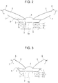
- a speaker in the embodiment of the present invention mainly includes a magnetic circuit 1 having a magnetic gap G, a voice coil 2, which is placed in the magnetic gap G and is driven due to electromagnetic interaction when a current passes, a bobbin 3, which is cylindrical and on which the voice coil 2 is formed, a cap 4 that blocks an opening formed at the top of the bobbin 3, a diaphragm 5 that vibrates together with the bobbin 3, a frame 7 that elastically supports the outer circumferential edge of the diaphragm 5 with an edge member 6 intervening therebetween, and a damper 8 disposed between the frame 7 and the upper end of the bobbin 3.
- the magnetic circuit 1 is composed of a bottom plate 9 having a center pole 9a, a magnet 10, in a circular ring shape, which is placed on the bottom plate 9, and a top plate 11 in a circular ring shape, which is integrally placed on the bottom plate 9 with the magnet 10 intervening therebetween.
- the magnetic gap G is formed between the outer circumferential surface of the center pole 9a and the inner circumferential surface of the top plate 11.
- the diaphragm 5 is a non-circular diaphragm having an elliptical outer shape.
- the central portion of the diaphragm 5 is fixedly bonded to the upper end of the bobbin 3.
- the diaphragm 5 has a non-axisymmetric shape with respect to a center axis passing through the center of the bobbin 3. Due to this non-axisymmetric shape, the shape stiffness of the diaphragm 5 is not uniform.
- the strength in the short-axis direction is lower than in the long-axis direction.
- the damper 8 is disposed between the frame 7 and the inner circumferential edge of the diaphragm 5.
- the diaphragm 5 is supported by the frame 7 so that the diaphragm 5 is vibrated by the damper 8 along the axial line of the bobbin 3.
- the diaphragm 5 is made of a sheet-like raw material in which fibrous fillers are oriented in one direction in polyamide resin or a thermoplastic resin such as polyamide resin.
- a thermoplastic carbon fiber reinforced plastic (CFRP) sheet (N6/CF is 20%) is used in which long-fiber (such as carbon fiber with a length of 4 mm to 12 mm) fillers are oriented in nylon 6 resin in one direction.
- CFRP thermoplastic carbon fiber reinforced plastic
- the diaphragm 5 is formed by vacuum molding of the thermoplastic CFRP sheet. During the vacuum molding, the orientation of the long-fiber fillers is set toward radial direction in areas on the diaphragm 5, the areas having lower shape stiffness.
- the orientation of the long-fiber fillers is set so as to match the short-axis direction of the diaphragm 5, as indicated by the arrows in Fig. 1 . That is, if the material stiffness of the diaphragm 5 is assumed to be uniform, first areas in which the amount of warp of the diaphragm 5 is increased during vibration appear in the short-axis direction and second areas in which the amount of warp is reduced during vibration appear in the long-axis direction. Therefore, to reduce the amount of warp in the first areas, the orientation of the fibrous fillers is set so as to match the short-axis direction.
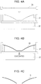
- thermoplastic CFRP sheet 20 is heated with a heater (not illustrated) to soften the thermoplastic CFRP sheet 20 as illustrated in Fig. 4A .
- the thermoplastic CFRP sheet 20 is then lowered toward a die 21 while the state of the thermoplastic CFRP sheet 20 is maintained. At that time, it is necessary to place the thermoplastic CFRP sheet 20 on the die 21 so that the orientation of the long-fiber fillers included in the thermoplastic CFRP sheet 20 matches the short-axis direction of the diaphragm 5 obtained after the vacuum molding.
- thermoplastic CFRP sheet 20 is cooled to solidify it, after which the thermoplastic CFRP sheet 20 is taken out of the die 21. Then, the outer circumferential edge and central portion of the thermoplastic CFRP sheet 20 are die-cut. This completes the manufacturing of the diaphragm 5 in a non-axisymmetric shape in which the outer shape is elliptical as illustrated in Fig. 4C .
- the diaphragm 5 has an elliptical shape that is non-axisymmetric with respect to a center axis passing through the center of the bobbin 3.
- the diaphragm 5 is made of a sheet-like raw material (thermoplastic CFRP sheet 20) in which long-fiber fillers are oriented in one direction in a thermoplastic resin.
- the orientation of the long-fiber fillers is set so as to match the short-axis direction of the diaphragm 5. Therefore, the mechanical strength at portions, on the diaphragm 5, at which its shape stiffness is low can be improved by the long-fiber fillers oriented in this way. This eliminates the trouble to add thick portions or reinforcing members to the diaphragm 5.
- the diaphragm 5 is obtained from a sheet-like raw material (thermoplastic CFRP sheet 20) by vacuum molding in which the thermoplastic CFRP sheet 20 is brought into tight contact with the die 21 and the space between them is evacuated by the vacuum pump 22, the manufacturing cost including the price of the die 21 is low and the diaphragm 5 with a desired shape can be easily manufactured.
- the outer shape of the diaphragm 5 is not limited to an elliptical shape.
- the diaphragm 5 may have any other outer shape that is non-axisymmetric with respect to a center axis passing through the center of a bobbin.
- a diaphragm having a track shape or a polygonal shape may be used.
- Another example is a diaphragm called an oblique cone, in which a voice coil (bobbin) is placed at a position deviated from the central portion of the diaphragm.
- the orientation of long-fiber fillers is set so as to match the short-axis direction of the diaphragm 5 having an elliptical outer shape
- the non-uniformity of the shape stiffness of the diaphragm 5 is not determined according to only the outer shape but is determined according to a whole shape including a curved shape extending from the inner circumferential edge on the same side as the bobbin 3 to the outer circumferential edge on the same side as the edge member 6.
- vacuum molding is used as a means for manufacturing the diaphragm 5 from a sheet-like raw material (thermoplastic CFRP sheet 20)
- thermoplastic CFRP sheet 20 thermoplastic CFRP sheet 20
- pneumatic molding in which the sheet-like raw material is softened by being heated and the softened raw material is pressurized in a die to obtain a desired shape
- press molding in which the sheet-like raw material is softened by being heated and the softened raw material is clamped between an upper die and a lower die.
Landscapes
- Engineering & Computer Science (AREA)
- Physics & Mathematics (AREA)
- Acoustics & Sound (AREA)
- Signal Processing (AREA)
- Multimedia (AREA)
- Manufacturing & Machinery (AREA)
- Diaphragms For Electromechanical Transducers (AREA)
Applications Claiming Priority (1)
| Application Number | Priority Date | Filing Date | Title |
|---|---|---|---|
| JP2016182239A JP6275793B1 (ja) | 2016-09-16 | 2016-09-16 | スピーカ |
Publications (2)
| Publication Number | Publication Date |
|---|---|
| EP3297293A1 true EP3297293A1 (de) | 2018-03-21 |
| EP3297293B1 EP3297293B1 (de) | 2020-11-04 |
Family
ID=59887138
Family Applications (1)
| Application Number | Title | Priority Date | Filing Date |
|---|---|---|---|
| EP17191361.9A Active EP3297293B1 (de) | 2016-09-16 | 2017-09-15 | Lautsprecher |
Country Status (3)
| Country | Link |
|---|---|
| US (1) | US10250988B2 (de) |
| EP (1) | EP3297293B1 (de) |
| JP (1) | JP6275793B1 (de) |
Families Citing this family (4)
| Publication number | Priority date | Publication date | Assignee | Title |
|---|---|---|---|---|
| JP6275793B1 (ja) * | 2016-09-16 | 2018-02-07 | アルパイン株式会社 | スピーカ |
| JP6275297B1 (ja) * | 2017-01-31 | 2018-02-07 | アルパイン株式会社 | 音響装置 |
| JP1637328S (de) * | 2018-12-21 | 2019-07-29 | ||
| JP7706891B2 (ja) * | 2021-01-28 | 2025-07-14 | Tdk株式会社 | 振動デバイス |
Citations (6)
| Publication number | Priority date | Publication date | Assignee | Title |
|---|---|---|---|---|
| JPS5717300A (en) * | 1980-07-04 | 1982-01-28 | Victor Co Of Japan Ltd | Diaphragm plate for dynamic type electro-acoustic converter |
| JPS6437199A (en) * | 1987-08-01 | 1989-02-07 | Sony Corp | Speaker diaphragm |
| US20030223613A1 (en) * | 2002-06-04 | 2003-12-04 | Pioneer Corporation | Speaker diaphragm and manufacturing method thereof |
| JP2005223807A (ja) | 2004-02-09 | 2005-08-18 | Pioneer Electronic Corp | 振動板、その製造方法、および、スピーカ装置 |
| JP2009111802A (ja) | 2007-10-31 | 2009-05-21 | Panasonic Corp | スピーカ用振動板の製造方法及びこの製造方法により製造したスピーカ用振動板、同振動板を用いたスピーカ、同スピーカを用いた電子機器及び装置 |
| EP2432252A1 (de) * | 2009-05-12 | 2012-03-21 | Panasonic Corporation | Lautsprecher und tragbares elektronisches gerät |
Family Cites Families (13)
| Publication number | Priority date | Publication date | Assignee | Title |
|---|---|---|---|---|
| EP0680242B1 (de) * | 1994-04-25 | 2006-06-14 | Matsushita Electric Industrial Co., Ltd. | Ausgedehnter Lautsprecher |
| JP4519837B2 (ja) * | 2004-04-05 | 2010-08-04 | パナソニック株式会社 | スピーカ装置 |
| JP2007221417A (ja) * | 2006-02-16 | 2007-08-30 | Matsushita Electric Ind Co Ltd | スピーカ用振動板 |
| BRPI0822523A2 (pt) * | 2008-04-29 | 2018-06-05 | Thomson Licensing | método e sistema para adaptar correção antecipada de erro multicast através de redes sem fio |
| JPWO2011004478A1 (ja) * | 2009-07-09 | 2012-12-13 | パイオニア株式会社 | スピーカ装置 |
| JP2011091645A (ja) * | 2009-10-22 | 2011-05-06 | Sony Corp | スピーカ振動板及びスピーカ装置 |
| ES2956670T3 (es) | 2010-11-23 | 2023-12-26 | Dentsply Sirona Inc | Material dental de alta resistencia |
| JP5683510B2 (ja) * | 2012-02-02 | 2015-03-11 | 三菱電機株式会社 | 振動板、それを用いたスピーカ、および、振動板の製造方法 |
| CN105122838B (zh) * | 2013-02-27 | 2018-08-21 | Gp 声学(英国)有限公司 | 电声学隔膜 |
| JP5400246B1 (ja) * | 2013-06-10 | 2014-01-29 | ディービーテクノロジー株式会社 | スピーカおよびそのエッジ構造 |
| WO2015011903A1 (ja) * | 2013-07-25 | 2015-01-29 | パナソニックIpマネジメント株式会社 | ラウドスピーカ用振動板と、その振動板を用いたラウドスピーカ、および電子機器と、移動体装置 |
| CN105723741B (zh) * | 2014-09-08 | 2019-10-01 | 松下知识产权经营株式会社 | 扬声器用振动板、扬声器、电子设备和移动体装置 |
| JP6275793B1 (ja) * | 2016-09-16 | 2018-02-07 | アルパイン株式会社 | スピーカ |
-
2016
- 2016-09-16 JP JP2016182239A patent/JP6275793B1/ja active Active
-
2017
- 2017-08-02 US US15/667,261 patent/US10250988B2/en active Active
- 2017-09-15 EP EP17191361.9A patent/EP3297293B1/de active Active
Patent Citations (6)
| Publication number | Priority date | Publication date | Assignee | Title |
|---|---|---|---|---|
| JPS5717300A (en) * | 1980-07-04 | 1982-01-28 | Victor Co Of Japan Ltd | Diaphragm plate for dynamic type electro-acoustic converter |
| JPS6437199A (en) * | 1987-08-01 | 1989-02-07 | Sony Corp | Speaker diaphragm |
| US20030223613A1 (en) * | 2002-06-04 | 2003-12-04 | Pioneer Corporation | Speaker diaphragm and manufacturing method thereof |
| JP2005223807A (ja) | 2004-02-09 | 2005-08-18 | Pioneer Electronic Corp | 振動板、その製造方法、および、スピーカ装置 |
| JP2009111802A (ja) | 2007-10-31 | 2009-05-21 | Panasonic Corp | スピーカ用振動板の製造方法及びこの製造方法により製造したスピーカ用振動板、同振動板を用いたスピーカ、同スピーカを用いた電子機器及び装置 |
| EP2432252A1 (de) * | 2009-05-12 | 2012-03-21 | Panasonic Corporation | Lautsprecher und tragbares elektronisches gerät |
Also Published As
| Publication number | Publication date |
|---|---|
| JP2018046532A (ja) | 2018-03-22 |
| JP6275793B1 (ja) | 2018-02-07 |
| US20180084345A1 (en) | 2018-03-22 |
| EP3297293B1 (de) | 2020-11-04 |
| US10250988B2 (en) | 2019-04-02 |
Similar Documents
| Publication | Publication Date | Title |
|---|---|---|
| US10250988B2 (en) | Speaker | |
| KR101690830B1 (ko) | 진동 제한을 위한 시스템 | |
| US20190261091A1 (en) | Speaker diaphragm, speaker including same, and method for manufacturing speaker diaphragm | |
| CN108377439B (zh) | 音响装置 | |
| KR20160130797A (ko) | 스피커 진동 시스템 | |
| JP2002159091A (ja) | スピーカ及び振動板並びに振動板の製造方法 | |
| EP3573347A1 (de) | Elektroakustischer wandler | |
| US10250970B2 (en) | Acoustic apparatus | |
| US11212616B2 (en) | Bonding structure of diaphragm for receiver | |
| US7929724B2 (en) | Loudspeaker | |
| JP5253216B2 (ja) | 音響振動板とその製造方法、及び電気音響変換器 | |
| JP4611887B2 (ja) | スピーカ用エッジの製造方法 | |
| US20090026007A1 (en) | Loudspeaker with an acoustic member | |
| JP6995435B2 (ja) | スピーカ | |
| EP3469813B1 (de) | Elektroakustischer treiber | |
| KR102744118B1 (ko) | 방수용 마이크로스피커 진동판 | |
| JP2025186574A (ja) | 振動板 | |
| JP2007325093A (ja) | スピーカエッジ及びその製造方法 | |
| HK1184004B (en) | System for vibration confinement |
Legal Events
| Date | Code | Title | Description |
|---|---|---|---|
| PUAI | Public reference made under article 153(3) epc to a published international application that has entered the european phase |
Free format text: ORIGINAL CODE: 0009012 |
|
| STAA | Information on the status of an ep patent application or granted ep patent |
Free format text: STATUS: THE APPLICATION HAS BEEN PUBLISHED |
|
| AK | Designated contracting states |
Kind code of ref document: A1 Designated state(s): AL AT BE BG CH CY CZ DE DK EE ES FI FR GB GR HR HU IE IS IT LI LT LU LV MC MK MT NL NO PL PT RO RS SE SI SK SM TR |
|
| AX | Request for extension of the european patent |
Extension state: BA ME |
|
| STAA | Information on the status of an ep patent application or granted ep patent |
Free format text: STATUS: REQUEST FOR EXAMINATION WAS MADE |
|
| 17P | Request for examination filed |
Effective date: 20180912 |
|
| RBV | Designated contracting states (corrected) |
Designated state(s): AL AT BE BG CH CY CZ DE DK EE ES FI FR GB GR HR HU IE IS IT LI LT LU LV MC MK MT NL NO PL PT RO RS SE SI SK SM TR |
|
| STAA | Information on the status of an ep patent application or granted ep patent |
Free format text: STATUS: EXAMINATION IS IN PROGRESS |
|
| 17Q | First examination report despatched |
Effective date: 20190909 |
|
| GRAP | Despatch of communication of intention to grant a patent |
Free format text: ORIGINAL CODE: EPIDOSNIGR1 |
|
| STAA | Information on the status of an ep patent application or granted ep patent |
Free format text: STATUS: GRANT OF PATENT IS INTENDED |
|
| INTG | Intention to grant announced |
Effective date: 20200602 |
|
| GRAS | Grant fee paid |
Free format text: ORIGINAL CODE: EPIDOSNIGR3 |
|
| GRAA | (expected) grant |
Free format text: ORIGINAL CODE: 0009210 |
|
| STAA | Information on the status of an ep patent application or granted ep patent |
Free format text: STATUS: THE PATENT HAS BEEN GRANTED |
|
| AK | Designated contracting states |
Kind code of ref document: B1 Designated state(s): AL AT BE BG CH CY CZ DE DK EE ES FI FR GB GR HR HU IE IS IT LI LT LU LV MC MK MT NL NO PL PT RO RS SE SI SK SM TR |
|
| REG | Reference to a national code |
Ref country code: GB Ref legal event code: FG4D |
|
| REG | Reference to a national code |
Ref country code: CH Ref legal event code: EP |
|
| REG | Reference to a national code |
Ref country code: AT Ref legal event code: REF Ref document number: 1332384 Country of ref document: AT Kind code of ref document: T Effective date: 20201115 |
|
| REG | Reference to a national code |
Ref country code: DE Ref legal event code: R096 Ref document number: 602017026702 Country of ref document: DE |
|
| REG | Reference to a national code |
Ref country code: IE Ref legal event code: FG4D |
|
| REG | Reference to a national code |
Ref country code: NL Ref legal event code: MP Effective date: 20201104 |
|
| REG | Reference to a national code |
Ref country code: AT Ref legal event code: MK05 Ref document number: 1332384 Country of ref document: AT Kind code of ref document: T Effective date: 20201104 |
|
| PG25 | Lapsed in a contracting state [announced via postgrant information from national office to epo] |
Ref country code: NO Free format text: LAPSE BECAUSE OF FAILURE TO SUBMIT A TRANSLATION OF THE DESCRIPTION OR TO PAY THE FEE WITHIN THE PRESCRIBED TIME-LIMIT Effective date: 20210204 Ref country code: PT Free format text: LAPSE BECAUSE OF FAILURE TO SUBMIT A TRANSLATION OF THE DESCRIPTION OR TO PAY THE FEE WITHIN THE PRESCRIBED TIME-LIMIT Effective date: 20210304 Ref country code: RS Free format text: LAPSE BECAUSE OF FAILURE TO SUBMIT A TRANSLATION OF THE DESCRIPTION OR TO PAY THE FEE WITHIN THE PRESCRIBED TIME-LIMIT Effective date: 20201104 Ref country code: FI Free format text: LAPSE BECAUSE OF FAILURE TO SUBMIT A TRANSLATION OF THE DESCRIPTION OR TO PAY THE FEE WITHIN THE PRESCRIBED TIME-LIMIT Effective date: 20201104 Ref country code: GR Free format text: LAPSE BECAUSE OF FAILURE TO SUBMIT A TRANSLATION OF THE DESCRIPTION OR TO PAY THE FEE WITHIN THE PRESCRIBED TIME-LIMIT Effective date: 20210205 |
|
| PG25 | Lapsed in a contracting state [announced via postgrant information from national office to epo] |
Ref country code: SE Free format text: LAPSE BECAUSE OF FAILURE TO SUBMIT A TRANSLATION OF THE DESCRIPTION OR TO PAY THE FEE WITHIN THE PRESCRIBED TIME-LIMIT Effective date: 20201104 Ref country code: BG Free format text: LAPSE BECAUSE OF FAILURE TO SUBMIT A TRANSLATION OF THE DESCRIPTION OR TO PAY THE FEE WITHIN THE PRESCRIBED TIME-LIMIT Effective date: 20210204 Ref country code: LV Free format text: LAPSE BECAUSE OF FAILURE TO SUBMIT A TRANSLATION OF THE DESCRIPTION OR TO PAY THE FEE WITHIN THE PRESCRIBED TIME-LIMIT Effective date: 20201104 Ref country code: PL Free format text: LAPSE BECAUSE OF FAILURE TO SUBMIT A TRANSLATION OF THE DESCRIPTION OR TO PAY THE FEE WITHIN THE PRESCRIBED TIME-LIMIT Effective date: 20201104 Ref country code: IS Free format text: LAPSE BECAUSE OF FAILURE TO SUBMIT A TRANSLATION OF THE DESCRIPTION OR TO PAY THE FEE WITHIN THE PRESCRIBED TIME-LIMIT Effective date: 20210304 Ref country code: AT Free format text: LAPSE BECAUSE OF FAILURE TO SUBMIT A TRANSLATION OF THE DESCRIPTION OR TO PAY THE FEE WITHIN THE PRESCRIBED TIME-LIMIT Effective date: 20201104 Ref country code: ES Free format text: LAPSE BECAUSE OF FAILURE TO SUBMIT A TRANSLATION OF THE DESCRIPTION OR TO PAY THE FEE WITHIN THE PRESCRIBED TIME-LIMIT Effective date: 20201104 |
|
| REG | Reference to a national code |
Ref country code: LT Ref legal event code: MG9D |
|
| PG25 | Lapsed in a contracting state [announced via postgrant information from national office to epo] |
Ref country code: HR Free format text: LAPSE BECAUSE OF FAILURE TO SUBMIT A TRANSLATION OF THE DESCRIPTION OR TO PAY THE FEE WITHIN THE PRESCRIBED TIME-LIMIT Effective date: 20201104 |
|
| PG25 | Lapsed in a contracting state [announced via postgrant information from national office to epo] |
Ref country code: SK Free format text: LAPSE BECAUSE OF FAILURE TO SUBMIT A TRANSLATION OF THE DESCRIPTION OR TO PAY THE FEE WITHIN THE PRESCRIBED TIME-LIMIT Effective date: 20201104 Ref country code: RO Free format text: LAPSE BECAUSE OF FAILURE TO SUBMIT A TRANSLATION OF THE DESCRIPTION OR TO PAY THE FEE WITHIN THE PRESCRIBED TIME-LIMIT Effective date: 20201104 Ref country code: EE Free format text: LAPSE BECAUSE OF FAILURE TO SUBMIT A TRANSLATION OF THE DESCRIPTION OR TO PAY THE FEE WITHIN THE PRESCRIBED TIME-LIMIT Effective date: 20201104 Ref country code: CZ Free format text: LAPSE BECAUSE OF FAILURE TO SUBMIT A TRANSLATION OF THE DESCRIPTION OR TO PAY THE FEE WITHIN THE PRESCRIBED TIME-LIMIT Effective date: 20201104 Ref country code: SM Free format text: LAPSE BECAUSE OF FAILURE TO SUBMIT A TRANSLATION OF THE DESCRIPTION OR TO PAY THE FEE WITHIN THE PRESCRIBED TIME-LIMIT Effective date: 20201104 Ref country code: LT Free format text: LAPSE BECAUSE OF FAILURE TO SUBMIT A TRANSLATION OF THE DESCRIPTION OR TO PAY THE FEE WITHIN THE PRESCRIBED TIME-LIMIT Effective date: 20201104 |
|
| REG | Reference to a national code |
Ref country code: DE Ref legal event code: R097 Ref document number: 602017026702 Country of ref document: DE |
|
| PG25 | Lapsed in a contracting state [announced via postgrant information from national office to epo] |
Ref country code: DK Free format text: LAPSE BECAUSE OF FAILURE TO SUBMIT A TRANSLATION OF THE DESCRIPTION OR TO PAY THE FEE WITHIN THE PRESCRIBED TIME-LIMIT Effective date: 20201104 |
|
| PLBE | No opposition filed within time limit |
Free format text: ORIGINAL CODE: 0009261 |
|
| STAA | Information on the status of an ep patent application or granted ep patent |
Free format text: STATUS: NO OPPOSITION FILED WITHIN TIME LIMIT |
|
| 26N | No opposition filed |
Effective date: 20210805 |
|
| PG25 | Lapsed in a contracting state [announced via postgrant information from national office to epo] |
Ref country code: AL Free format text: LAPSE BECAUSE OF FAILURE TO SUBMIT A TRANSLATION OF THE DESCRIPTION OR TO PAY THE FEE WITHIN THE PRESCRIBED TIME-LIMIT Effective date: 20201104 Ref country code: NL Free format text: LAPSE BECAUSE OF FAILURE TO SUBMIT A TRANSLATION OF THE DESCRIPTION OR TO PAY THE FEE WITHIN THE PRESCRIBED TIME-LIMIT Effective date: 20201104 Ref country code: IT Free format text: LAPSE BECAUSE OF FAILURE TO SUBMIT A TRANSLATION OF THE DESCRIPTION OR TO PAY THE FEE WITHIN THE PRESCRIBED TIME-LIMIT Effective date: 20201104 |
|
| PG25 | Lapsed in a contracting state [announced via postgrant information from national office to epo] |
Ref country code: SI Free format text: LAPSE BECAUSE OF FAILURE TO SUBMIT A TRANSLATION OF THE DESCRIPTION OR TO PAY THE FEE WITHIN THE PRESCRIBED TIME-LIMIT Effective date: 20201104 |
|
| REG | Reference to a national code |
Ref country code: CH Ref legal event code: PL |
|
| REG | Reference to a national code |
Ref country code: BE Ref legal event code: MM Effective date: 20210930 |
|
| PG25 | Lapsed in a contracting state [announced via postgrant information from national office to epo] |
Ref country code: IS Free format text: LAPSE BECAUSE OF FAILURE TO SUBMIT A TRANSLATION OF THE DESCRIPTION OR TO PAY THE FEE WITHIN THE PRESCRIBED TIME-LIMIT Effective date: 20210304 Ref country code: MC Free format text: LAPSE BECAUSE OF FAILURE TO SUBMIT A TRANSLATION OF THE DESCRIPTION OR TO PAY THE FEE WITHIN THE PRESCRIBED TIME-LIMIT Effective date: 20201104 |
|
| PG25 | Lapsed in a contracting state [announced via postgrant information from national office to epo] |
Ref country code: LU Free format text: LAPSE BECAUSE OF NON-PAYMENT OF DUE FEES Effective date: 20210915 Ref country code: IE Free format text: LAPSE BECAUSE OF NON-PAYMENT OF DUE FEES Effective date: 20210915 Ref country code: BE Free format text: LAPSE BECAUSE OF NON-PAYMENT OF DUE FEES Effective date: 20210930 |
|
| PG25 | Lapsed in a contracting state [announced via postgrant information from national office to epo] |
Ref country code: LI Free format text: LAPSE BECAUSE OF NON-PAYMENT OF DUE FEES Effective date: 20210930 Ref country code: CH Free format text: LAPSE BECAUSE OF NON-PAYMENT OF DUE FEES Effective date: 20210930 |
|
| PG25 | Lapsed in a contracting state [announced via postgrant information from national office to epo] |
Ref country code: HU Free format text: LAPSE BECAUSE OF FAILURE TO SUBMIT A TRANSLATION OF THE DESCRIPTION OR TO PAY THE FEE WITHIN THE PRESCRIBED TIME-LIMIT; INVALID AB INITIO Effective date: 20170915 |
|
| PG25 | Lapsed in a contracting state [announced via postgrant information from national office to epo] |
Ref country code: CY Free format text: LAPSE BECAUSE OF FAILURE TO SUBMIT A TRANSLATION OF THE DESCRIPTION OR TO PAY THE FEE WITHIN THE PRESCRIBED TIME-LIMIT Effective date: 20201104 |
|
| PG25 | Lapsed in a contracting state [announced via postgrant information from national office to epo] |
Ref country code: MK Free format text: LAPSE BECAUSE OF FAILURE TO SUBMIT A TRANSLATION OF THE DESCRIPTION OR TO PAY THE FEE WITHIN THE PRESCRIBED TIME-LIMIT Effective date: 20201104 |
|
| PG25 | Lapsed in a contracting state [announced via postgrant information from national office to epo] |
Ref country code: TR Free format text: LAPSE BECAUSE OF FAILURE TO SUBMIT A TRANSLATION OF THE DESCRIPTION OR TO PAY THE FEE WITHIN THE PRESCRIBED TIME-LIMIT Effective date: 20201104 |
|
| PG25 | Lapsed in a contracting state [announced via postgrant information from national office to epo] |
Ref country code: MT Free format text: LAPSE BECAUSE OF FAILURE TO SUBMIT A TRANSLATION OF THE DESCRIPTION OR TO PAY THE FEE WITHIN THE PRESCRIBED TIME-LIMIT Effective date: 20201104 |
|
| PGFP | Annual fee paid to national office [announced via postgrant information from national office to epo] |
Ref country code: DE Payment date: 20250919 Year of fee payment: 9 |
|
| PGFP | Annual fee paid to national office [announced via postgrant information from national office to epo] |
Ref country code: GB Payment date: 20250919 Year of fee payment: 9 |
|
| PGFP | Annual fee paid to national office [announced via postgrant information from national office to epo] |
Ref country code: FR Payment date: 20250922 Year of fee payment: 9 |