EP3296590B1 - Rotationsübertragungsvorrichtung - Google Patents
Rotationsübertragungsvorrichtung Download PDFInfo
- Publication number
- EP3296590B1 EP3296590B1 EP17184715.5A EP17184715A EP3296590B1 EP 3296590 B1 EP3296590 B1 EP 3296590B1 EP 17184715 A EP17184715 A EP 17184715A EP 3296590 B1 EP3296590 B1 EP 3296590B1
- Authority
- EP
- European Patent Office
- Prior art keywords
- gear
- rotation transmission
- linking part
- rotation
- rotating member
- Prior art date
- Legal status (The legal status is an assumption and is not a legal conclusion. Google has not performed a legal analysis and makes no representation as to the accuracy of the status listed.)
- Active
Links
Images





Classifications
-
- F—MECHANICAL ENGINEERING; LIGHTING; HEATING; WEAPONS; BLASTING
- F16—ENGINEERING ELEMENTS AND UNITS; GENERAL MEASURES FOR PRODUCING AND MAINTAINING EFFECTIVE FUNCTIONING OF MACHINES OR INSTALLATIONS; THERMAL INSULATION IN GENERAL
- F16H—GEARING
- F16H1/00—Toothed gearings for conveying rotary motion
- F16H1/02—Toothed gearings for conveying rotary motion without gears having orbital motion
- F16H1/04—Toothed gearings for conveying rotary motion without gears having orbital motion involving only two intermeshing members
- F16H1/06—Toothed gearings for conveying rotary motion without gears having orbital motion involving only two intermeshing members with parallel axes
-
- F—MECHANICAL ENGINEERING; LIGHTING; HEATING; WEAPONS; BLASTING
- F16—ENGINEERING ELEMENTS AND UNITS; GENERAL MEASURES FOR PRODUCING AND MAINTAINING EFFECTIVE FUNCTIONING OF MACHINES OR INSTALLATIONS; THERMAL INSULATION IN GENERAL
- F16H—GEARING
- F16H57/00—General details of gearing
- F16H57/12—Arrangements for adjusting or for taking-up backlash not provided for elsewhere
-
- F—MECHANICAL ENGINEERING; LIGHTING; HEATING; WEAPONS; BLASTING
- F16—ENGINEERING ELEMENTS AND UNITS; GENERAL MEASURES FOR PRODUCING AND MAINTAINING EFFECTIVE FUNCTIONING OF MACHINES OR INSTALLATIONS; THERMAL INSULATION IN GENERAL
- F16H—GEARING
- F16H57/00—General details of gearing
- F16H57/02—Gearboxes; Mounting gearing therein
- F16H57/021—Shaft support structures, e.g. partition walls, bearing eyes, casing walls or covers with bearings
- F16H57/022—Adjustment of gear shafts or bearings
- F16H2057/0222—Lateral adjustment
-
- F—MECHANICAL ENGINEERING; LIGHTING; HEATING; WEAPONS; BLASTING
- F16—ENGINEERING ELEMENTS AND UNITS; GENERAL MEASURES FOR PRODUCING AND MAINTAINING EFFECTIVE FUNCTIONING OF MACHINES OR INSTALLATIONS; THERMAL INSULATION IN GENERAL
- F16H—GEARING
- F16H57/00—General details of gearing
- F16H57/12—Arrangements for adjusting or for taking-up backlash not provided for elsewhere
- F16H2057/126—Self-adjusting during operation, e.g. by a spring
- F16H2057/127—Self-adjusting during operation, e.g. by a spring using springs
Definitions
- the present invention relates to a rotation transmission device that transmits rotation between gears.
- a motor-driven gear and a gear that rotates together with an operated body operated so as to be rotated are linked together through a driving force transmission mechanism.
- helical gears are sometimes used to reduce backlash between gears constituting a rotation transmission device.
- a related technique is disclosed in, for example, Japanese Unexamined Patent Application Publication No. 2004-234072 .
- JP H11 141623 A shows a rotation transmission device having one rotation shaft comprising a first gear at a first end and a second gear at a second end.
- the rotation shaft is urged towards a large gear by a separately arranged leaf spring.
- the transmission device comprises an input shaft with a first gear, an output shaft with a fourth gear, and a movable shaft having a second gear and a third gear at opposite ends of the movable shaft.
- the first gear meshes with the second gear
- the third gear meshes with the fourth gear.
- the movable shaft is supported by two bearings.
- the bearings are each movably supported by leaf springs, and a coil spring provides an urging force to the bearings such that the movable shaft is urged towards the input shaft and the output shaft to bring the first and second gears and the third and fourth gears close to each other.
- Helical gears are effective in that the amount of backlash between them is smaller than when spur gears are used.
- these helical gears are problematic in that, to mold them, a metal mold needs to be moved up and down while being rotated, so the metal mold is expensive.
- Another problem is that a time (shot cycle) taken to manufacture gears is prolonged and parts thereby become expensive.
- the present invention addresses the above situation by providing a rotation transmission device that uses inexpensive spur gears and still reduces backlash.
- a rotation transmission device in the present invention has a first gear, a second gear, and a rotation transmission part configured to transmit rotation between the first gear and the second gear.
- the rotation transmission part has a linking part, a third gear provided at one end of the linking part so as to engage the first gear, a fourth gear provided at another end of the linking part so as to engage the second gear, a supporting part configured to support the linking part so as to be inclinable and rotatable, and an urging part configured to urge the linking part so that the third gear is pressed to the first gear and the fourth gear is pressed to the second gear.
- At least one of a first combination of the first gear and third gear and a second combination of the second gear and fourth gear is a combination of spur gears.
- the urging part presses the third gear to the first gear and also presses the fourth gear to the second gear
- the first gear and third gear are engaged with each other with at least a prescribed pressing force
- the second gear and fourth gear are engaged with each other with at least the prescribed pressing force. Therefore, even if at least one of the first combination of the first gear and third gear and the second combination of the second gear and fourth gear is a combination of spur gears, backlash can be reduced and operability can be enhanced.
- the supporting member supports the linking part so as to be inclinable and rotatable, the third gear and fourth gear can be restricted to predetermined positions and can be supported there. This enables the linking part to be rotated in a stable orientation.
- the present invention preferably has a supporting body having an accommodating part formed so as to accommodate the linking part by enclosing it.
- the supporting part is formed integrally with the supporting body.
- the supporting part is formed integrally with the supporting body, the number of parts can be reduced and the manufacturing cost can be suppressed.
- the inner circumferential surface of the accommodating part of the present invention is preferably spaced from the linking part.
- the urging part of the present invention is preferably a leaf spring that is formed integrally with the supporting body and presses the outer circumferential surface of the linking part.
- the urging part is formed integrally with the supporting body, the function of the supporting part can be achieved by a single part and the rotation transmission device is compact and easy to assemble without having to increase the number of parts.
- the present invention preferably has a plurality of urging parts.
- the plurality of urging parts urge the linking part in such a way that they enclose the linking part. This can stabilize the orientation of the linking part and can achieve a superior operational feeling.
- the linking part of the present invention preferably has an engaging part configured to engage the supporting part and restrict the movement of the linking part in an axial direction.
- the engaging part of the present invention is preferably a leaf spring formed integrally with the linking part.
- the engaging part is formed integrally with the linking part, the number of parts is not increased.
- the first linking part is distorted in a radial direction. This enables the rotation transmission device to be easily assembled.
- the linking part of the present invention is preferably structured by combining the third gear and fourth gear, which are formed separately.
- the linking part can be molded without having to use slide mold parts. This enables the costs of a metal mold and parts to be reduced.
- the first gear of the present invention rotates together with an operated body on which a rotation operation is performed, and the rotation of the second gear is driven by a motor to perform, for the operated body, a rotation operation to provide force sensation.
- a rotation transmission device in an embodiment of the present invention will be described below.
- the rotation transmission device is applied to a rotation operation device with force sensation.
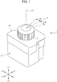
- Fig. 1 is an external perspective view of a rotation operation device 1 in an embodiment of the present invention.
- the Z1 direction is taken as the upward direction, the Z2 direction as the downward direction, the Y1 direction as the forward direction, the Y2 direction as the backward direction, the X1 direction as the right direction, and the X2 direction as the left direction.
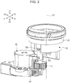
- Fig. 2 is an external perspective view illustrating the internal structure of the rotation operation device 1 in Fig. 1 .
- Fig. 3 is an external perspective view illustrating the internal structure of the rotation operation device 1 in a state in which the rotating member 20 in Fig. 2 is removed.
- Fig. 4 is an external perspective view of the rotating member 20 in Fig. 2 .
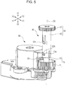
- Fig. 5 is an external perspective view of a rotation transmission part 40 and a motor 80.
- Fig. 6 is an exploded perspective view of a supporting body 30, the rotation transmission part 40, and the motor 80.
- Fig. 7 is a perspective view illustrating a state in which the rotating member 20 and rotation transmission part 40 engage each other.
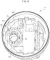
- Fig. 8 is a perspective view of the supporting body 30 as viewed from Z1 in the Z2 direction.
- the rotation operation device 1 has a supporting body 10, the supporting body 30 secured to the supporting body 10, the rotating member 20 rotatably supported to the supporting body 30, and an operated body 2 secured to the rotating member 20 at an end of the supporting body 30 in the Z1 direction.
- the supporting body 10 is a housing formed from a synthetic resin. As illustrated in Fig. 1 , the supporting body 10 is covered with a decorative cover 18 on the Z1 side.
- the operated body 2 and rotating member 20 rotate together around a rotation reference line O1.
- the rotational angle of the operated body 2 and rotating member 20 with reference to a neutral position (N) is detected by a rotational angle sensor (not illustrated).
- certain rotational load torque is constantly applied to the operated body 2 and rotating member 20 by the motor 80, which will be described later, in a direction opposite to a direction in which the operated body 2 is operated.
- the operated body 2 is operated so as to be rotated while being given force sensation under strong rotational load torque so that the operator has a click feeling each time the operated body 2 is rotated in one direction by an angle of + ⁇ degrees from the neutral position (N).
- the operated body 2 is operated so as to be rotated while being given force sensation under strong rotational load torque so that the operator has a click feeling each time the operated body 2 is rotated in the other direction by an angle of - ⁇ degrees.
- the operator can perform a rotational input operation while having force sensation called a click feeling at intervals of + ⁇ degrees or - ⁇ degrees from the neutral position (N).
- a click feeling at intervals of + ⁇ degrees or - ⁇ degrees from the neutral position (N).
- the supporting body 10 internally includes an electric switching means that selects an electric output according to the rotational angle of the rotating member 20.
- an electric switching means that selects an electric output according to the rotational angle of the rotating member 20.
- a control integrated circuit (IC) chip mounted on a circuit board receives a result of rotational angle detection by the rotational angle sensor in the rotating member 20, makes a decision according to the result, and produces a predetermined electric output as a signal accordingly. Therefore, a rotation input device can be configured in which an electric output from the IC chip is changed each time the rotating member 20 is rotated by a rotational angle of + ⁇ degrees or - ⁇ degrees.
- the inner circumferential surface 20b, illustrated in Fig. 4 , of the rotating member 20 is matched to the outer circumferential surface 30f, illustrated in Fig. 3 , of the supporting body 30, and the rotating member 20 is attached to the supporting body 30 so as to be rotatable around the rotation reference line O1.
- the first spur gear (inner gear) 20a illustrated in Fig. 4 as a first gear
- a third spur gear 61 illustrated in Fig. 3 , that protrudes from an opening 30a formed in the supporting body 30.
- the opening 30a is circumferentially formed in the outer circumferential surface 30f of the supporting body 30, the rotating member 20 being attached to the outer circumferential surface 30f.
- Part of the third spur gear 61 of the rotation transmission part 40 protrudes from the opening 30a so as to appear. As illustrated in Fig. 7 , the third spur gear 61 protruding from the opening 30a toward the outside engages the first spur gear 20a formed on the inner circumferential surface of the rotating member 20, which rotates together with the operated body 2.
- the rotation transmission part 40 is structured by a combination of a first rotating member 65 and a second rotating member 75.
- the first rotating member 65 has the third spur gear 61 and a first linking part 63, which is cylindrical, the third spur gear 61 being positioned at one end of the first linking part 63.
- the first linking part 63 has an opening 63a at an end opposite to the end at which the third spur gear 61 is disposed.
- the second rotating member 75 has a fourth spur gear 71 and a second linking part 73, which is cylindrical, the fourth spur gear 71 being positioned at one end of the second linking part 73.
- the second linking part 73 is inserted through the opening 63a, illustrated in Fig. 6 , in the first linking part 63 and is accommodated in the first linking part 63.
- a hook 73a provided on the outer circumferential surface of the second linking part 73 is fitted into an opening 63b formed in the outer circumferential surface of the first linking part 63 and is secured, as illustrated in Fig. 5 .
- two hooks 73a are provided at opposing positions on the outer circumferential surface of the second linking part 73.
- Each hook 73a is fitted into one of two openings 63b formed at opposing positions in the outer circumferential surface of the first linking part 63 and is secured.
- an engaging part 63c which is shaped like a hook and is provided on the outer circumferential surface of the first linking part 63, is engaged with a supporting part 30b on the outer circumferential surface of the supporting body 30 as illustrated in Fig. 2 .
- two engaging parts 63c are provided at opposing positions on the outer circumferential surface of the first linking part 63.
- Each engaging part 63c is engaged with one of two support parts 30b opposite to each other at the end of an accommodating part 30c, which is substantially cylindrical and is disposed in the supporting body 30, on the Z2 side (the accommodating part 30c will be described later).
- the engaging parts 63c are formed integrally with the first linking part 63.
- the support parts 30b are formed integrally with the supporting body 30.
- Each engaging part 63c engages the relevant supporting part 30b and restricts the movement of the rotation transmission part 40 in a direction along the rotation reference line 02. This can suppress the rotation transmission part 40 from going out of control in that direction.
- the fourth spur gear 71 of the second rotating member 75 engages a second spur gear 83 driven by the motor 80.
- the supporting body 30 has the accommodating part 30c, which is substantially cylindrical and passes through the supporting body 30 in the Z1-Z2 direction. Part of the first linking part 63 of the first rotating member 65 is accommodated in the accommodating part 30c.
- the end of the accommodating part 30c in the Z2 direction is a ring-shaped surface that has a constant height in the Z direction and circumferentially continuous.
- the supporting parts 30b are formed, which engage the engaging parts 63c of the first linking part 63, described above, in a state in which the supporting parts 30b are opposite to the engaging parts 63c.
- an accommodating space 30d is formed that forms an accommodating space together with the accommodating part 30c, the third spur gear 61 being accommodated in the accommodating space 30d.
- the third spur gear 61 In a state in which the third spur gear 61 is accommodated in the accommodating space 30d, the third spur gear 61 is positioned outside the supporting body 30 through the opening 30a and engages the first spur gear 20a of the rotating member 20.
- An urging part 30e1 is provided at a position at which the urging part 30e1 faces the opening 30a formed in the accommodating part 30c of the supporting body 30.
- Urging parts 30e2 and 30e3 are provided at both sides of the urging parts 30e1.
- the opening 30a and urging parts 30e2, 30e1, and 30e3 are disposed along the inner circumference of the accommodating part 30c at angular intervals of about 90 degrees, as viewed from Z1 in the Z2 direction.
- the urging parts 30e1, 30e2, and 30e3 are each a leaf spring formed integrally with the supporting body 30.
- Fig. 9 is a cross-sectional view as taken along line IX-IX in Fig. 3 .
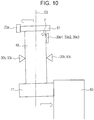
- Fig. 10 illustrates the orientation of the rotation transmission part 40 attached to the supporting body 30 at an angle.
- the urging parts 30e1, 30e2, and 30e3 abut the outer circumferential surface of the first linking part 63 and press the outer circumferential surface toward the rotation reference line 02.
- the rotation transmission part 40 is inclined by an urging force F generated by the urging parts 30e1, 30e2, and 30e3 while the rotation transmission part 40 is supported by the supporting part 30b, as illustrated in Fig. 10 .
- the rotation transmission part 40 is inclined in this way, the third spur gear 61 is pressed toward the first spur gear 20a and the fourth spur gear 71 is pressed toward the second spur gear 83.
- the third spur gear 61 comes close to and abuts the first spur gear 20a until a clearance between their routes is constantly eliminated so that the third spur gear 61 engages the first spur gear 20a while performing self-adjustment so as to narrow inter-gear pitches.
- the fourth spur gear 71 comes close to and abuts the second spur gear 83 until a clearance between their routes is constantly eliminated so that the fourth spur gear 71 engages the second spur gear 83 while performing self-adjustment so as to narrow inter-gear pitches.
- the third spur gear 61 illustrated in Fig. 5 , of the rotation transmission part 40 rotates around the rotation reference line 02, the third spur gear 61 engaging the first spur gear 20a disposed on the inner circumference of the rotating member 20 as illustrated in Fig. 7 .
- the first rotating member 65 rotates and the second rotating member 75 also rotates together with the first rotating member 65.
- the detection result of the rotation angle is input from the rotational angle sensor to the control IC chip described above, after which an electric signal decided on the basis of the detection result is output.
- the second spur gear 83 is driven by the motor 80 and rotates to provide force sensation.
- the rotation of the second spur gear 83 is transmitted to the fourth spur gear 71 engaging the second spur gear 83, rotating the rotation transmission part 40. Therefore, a desired rotation operation to provide force sensation is transmitted to the operated body 2 through the first spur gear 20a.
- a predetermined electric signal is output from the control IC chip each time the operated body 2 and rotating member 20 are rotated by the rotational angle (+ ⁇ or - ⁇ degrees) from the neutral position (N), so a rotation operation to provide force sensation that the operator can recognize as a click feeling is transmitted from the motor 80 to the operated body 2 at intervals of the rotational angle (+ ⁇ degrees or - ⁇ degrees).
- the urging parts 30e1, 30e2, and 30e3 abut the outer circumferential surface of the first linking part 63 on the Z1 side with respect to the supporting part 30b and press the outer circumferential surface on the Z1 side toward the rotation reference line 02, as illustrated in Figs. 9 and 10 , so the rotation transmission part 40 is inclined with respect to the rotation reference line 02. Therefore, the third spur gear 61 is pressed toward the first spur gear 20a and the fourth spur gear 71 is pressed toward the second spur gear 83.
- the third spur gear 61 comes close to and abuts the first spur gear 20a until a clearance between their routes is constantly eliminated so that the third spur gear 61 engages the first spur gear 20a while performing self-adjustment so as to narrow inter-gear pitches.
- the fourth spur gear 71 comes close to and abuts the second spur gear 83 until a clearance between their routes is constantly eliminated so that the fourth spur gear 71 engages the second spur gear 83 while performing self-adjustment so as to narrow inter-gear pitches.
- the rotation transmission part 40 is urged by the urging parts 30e1, 30e2, and 30e3 toward the rotation reference line 02 on the Z1 side with respect to the engaging parts 63c while the engaging parts 63c of the rotation transmission part 40 are supported by the supporting parts 30b of the supporting body 30. Therefore, the rotation transmission part 40 can be inclined as illustrated in Fig. 10 . Accordingly, the third spur gear 61 comes close to and abuts the first spur gear 20a until a clearance between their routes is constantly eliminated so that the third spur gear 61 engages the first spur gear 20a while performing self-adjustment so as to narrow inter-gear pitches.
- the fourth spur gear 71 comes close to and abuts the second spur gear 83 until a clearance between their routes is constantly eliminated so that the fourth spur gear 71 engages the second spur gear 83 while performing self-adjustment so as to narrow inter-gear pitches.
- rotation is performed without backlash between gears, achieving a high operational feeling.
- the rotation transmission part 40 has a certain amount of play, so the rotation transmission part 40 can be aligned with the rotation reference line 02 by being pressed from one direction.
- the supporting parts 30b support the rotation transmission part 40 so as to be inclinable and rotatable, the third spur gear 61 and fourth spur gear 71 can be restricted to predetermined positions and can be supported there. This enables the rotation transmission part 40 to be rotated in a stable orientation.
- the rotation operation device 1 since the supporting parts 30b are formed integrally with the supporting body 30, the number of parts can be reduced and the manufacturing cost can be suppressed.
- the inner circumferential surface of the accommodating part 30c of the supporting body 30 illustrated in Fig. 8 is spaced from the first linking part 63 of the rotation transmission part 40 in a state in which the rotation transmission part 40 is accommodated in the accommodating part 30c.
- the urging parts 30e1, 30e2, and 30e3 are each a leaf spring that is formed integrally with the supporting body 30 and presses the outer circumferential surface of the first linking part 63.
- the rotation operation device 1 is compact and easy to assemble without having to increase the number of parts.
- each engaging part 63c of the rotation transmission part 40 engages the relevant supporting part 30b and restricts the movement of the rotation transmission part 40 in a direction along the rotation reference line 02. This can suppress the rotation transmission part 40 from going out of control in that direction.
- the engaging part 63c is a leaf spring formed integrally with the first linking part 63, the number of parts is not increased.
- the first linking part 63 is distorted in a radial direction. This enables the rotation operation device 1 to be easily assembled.
- the rotation transmission part 40 can be molded without having to use slide mold parts. This enables the costs of a metal mold and parts to be reduced.
- the present invention is not limited to the embodiment described above.
- the fourth spur gear 71 engages the second spur gear 83, the rotation of which is driven by the motor 80, but the fourth spur gear 71 may engage a gear that is not motor-driven.
- the rotation transmission part 40 may be formed integrally with the third spur gear 61 and fourth spur gear 71.
- the motor 80 has performed a rotation operation to provide force sensation so that a click feeling is generated each time the operated body 2 is rotated by an angle of + ⁇ degrees or - ⁇ degrees, but another rotation operation to provide force sensation may be performed.
- a rotation operation to provide force sensation may be performed so that when a rotation of the operated body 2 by ⁇ degrees is detected, to prevent the operated body 2 from further rotating in the same direction, the motor 80 generates a strong rotational load to impose a restriction.
- the present invention can be applied to, for example, a rotation transmission device that uses gears to transmit rotation.
Landscapes
- Engineering & Computer Science (AREA)
- General Engineering & Computer Science (AREA)
- Mechanical Engineering (AREA)
- Mechanical Control Devices (AREA)
- Gear Transmission (AREA)
- Gears, Cams (AREA)
Claims (9)
- Rotationsübertragungsvorrichtung, aufweisend:ein erstes Zahnrad (20a);ein zweites Zahnrad (83); undein Rotationsübertragungsteil (40), das zum Übertragen von Rotation zwischen dem ersten Zahnrad (20a) und dem zweiten Zahnrad (83) ausgebildet ist;wobei das Rotationsübertragungsteil (40) aufweist:ein Verbindungsteil (63),ein drittes Zahnrad (61), das an einem Ende des Verbindungsteils (63) vorgesehen ist, um mit dem ersten Zahnrad (20a) zu kämmen,ein viertes Zahnrad (71), das an einem anderen Ende des Verbindungsteils (63) vorgesehen ist, um mit dem zweiten Zahnrad (83) zu kämmen, ein Abstützteil (30b), das zum derartigen Abstützen des Verbindungsteils (63) ausgebildet ist, dass dieses neigbar und drehbar ist, undein Drückteil (30e1), das dazu ausgebildet ist, das Verbindungsteil (63) derart mit Druck zu beaufschlagen, dass das dritte Zahnrad (61) gegen das erste Zahnrad (20a) gedrückt wird und das vierte Zahnrad (71) gegen das zweite Zahnrad (83) gedrückt wird, undwobei mindestens eine von einer ersten Kombination aus dem ersten Zahnrad (20a) und dem dritten Zahnrad (61) und einer zweiten Kombination aus dem zweiten Zahnrad (83) und dem vierten Zahnrad (71) eine Kombination von Stirnrädern ist;dadurch gekennzeichnet,dass das Rotationsübertragungsteil (40) durch eine Kombination aus einem ersten Rotationselement (65) und einem zweiten Rotationselement (75) aufgebaut ist, wobei das erste Rotationselement (65) das dritte Zahnrad (61) und das Verbindungsteil (63) aufweist, das zylindrisch ausgebildet ist, wobei das dritte Zahnrad (61) an einem Ende des Verbindungsteils (63) angeordnet ist; unddass das zweite Rotationselement (75) das vierte Zahnrad (71) und ein zweites Verbindungsteil (73) aufweist, das zylindrisch ausgebildet ist, wobei das vierte Zahnrad (71) an einem Ende des zweiten Verbindungsteils (73) angeordnet ist.
- Rotationsübertragungsvorrichtung nach Anspruch 1,
die ferner einen Abstützkörper (30) mit einem Aufnahmeteil (30c) aufweist, der derart ausgebildet ist, dass er das Verbindungsteil (63) aufnimmt, indem er das Verbindungsteil (63) umschließt, wobei
das Abstützteil (30b) einstückig mit dem Abstützkörper (30) ausgebildet ist. - Rotationsübertragungsvorrichtung nach Anspruch 2,
wobei eine Innenumfangsfläche des Aufnahmeteils (30c) von dem Verbindungsteil (63) beabstandet ist. - Rotationsübertragungsvorrichtung nach einem der Ansprüche 2 bis 3,
wobei das Drückteil (30e1) eine Blattfeder ist, die einstückig mit dem Abstützkörper (30) ausgebildet ist, wobei das Drückteil (30e1) gegen eine Außenumfangsfläche des Verbindungsteils (63) drückt. - Rotationsübertragungsvorrichtung nach einem der Ansprüche 1 bis 4,
wobei mehrere Drückteile (30e1, 30e2, 30e3) vorgesehen sind. - Rotationsübertragungsvorrichtung nach einem der Ansprüche 1 bis 5,
wobei das Verbindungsteil (63) ein Zusammenwirkungsteil (63c) aufweist, das dazu ausgebildet ist, mit dem Abstützteil (30b) zusammenzuwirken und eine Bewegung des Verbindungsteils (63) in einer axialen Richtung einzuschränken. - Rotationsübertragungsvorrichtung nach Anspruch 6,
wobei das Zusammenwirkungsteil (63c) eine Blattfeder ist, die einstückig mit dem Verbindungsteil (63) ausgebildet ist. - Rotationsübertragungsvorrichtung nach einem der Ansprüche 1 bis 7,
wobei das Verbindungsteil (63) durch Kombinieren des dritten Zahnrads (61) und des vierten Zahnrads (71) aufgebaut ist, die getrennt ausgebildet sind. - Rotationsübertragungsvorrichtung nach einem der Ansprüche 1 bis 8,
wobei sich das erste Zahnrad (20a) zusammen mit einem betätigten Körper (2) dreht, an dem ein Rotationsvorgang ausgeführt wird; und
wobei eine Drehung des zweiten Zahnrads (83) durch einen Motor (80) veranlasst wird, um für den betätigten Körper (2) einen Rotationsvorgang auszuführen und dabei ein Kraftgefühl bereitzustellen.
Applications Claiming Priority (1)
| Application Number | Priority Date | Filing Date | Title |
|---|---|---|---|
| JP2016171928A JP6792381B2 (ja) | 2016-09-02 | 2016-09-02 | 回転伝達装置 |
Publications (2)
| Publication Number | Publication Date |
|---|---|
| EP3296590A1 EP3296590A1 (de) | 2018-03-21 |
| EP3296590B1 true EP3296590B1 (de) | 2020-06-03 |
Family
ID=59523001
Family Applications (1)
| Application Number | Title | Priority Date | Filing Date |
|---|---|---|---|
| EP17184715.5A Active EP3296590B1 (de) | 2016-09-02 | 2017-08-03 | Rotationsübertragungsvorrichtung |
Country Status (2)
| Country | Link |
|---|---|
| EP (1) | EP3296590B1 (de) |
| JP (1) | JP6792381B2 (de) |
Family Cites Families (10)
| Publication number | Priority date | Publication date | Assignee | Title |
|---|---|---|---|---|
| JPS5612659Y2 (de) * | 1975-10-20 | 1981-03-24 | ||
| DE3114170A1 (de) * | 1981-04-08 | 1982-11-18 | Hans Heynau GmbH, 8000 München | Getriebe mit spielausgleich |
| JPH1054449A (ja) * | 1996-08-08 | 1998-02-24 | Higashifuji Seisakusho:Kk | クラッチ付きモータ |
| JPH11141623A (ja) * | 1997-11-06 | 1999-05-25 | Minolta Co Ltd | 歯車伝達機構 |
| JP2003139221A (ja) * | 2001-11-06 | 2003-05-14 | Funai Electric Co Ltd | ギア取り付け構造 |
| JP2004234072A (ja) | 2003-01-28 | 2004-08-19 | Alps Electric Co Ltd | トラックボール装置 |
| JP3706118B2 (ja) * | 2004-01-23 | 2005-10-12 | 川崎重工業株式会社 | 歯車支持構造 |
| WO2009151122A1 (ja) * | 2008-06-13 | 2009-12-17 | 株式会社アイカムス・ラボ | 動力伝達装置 |
| JP2011034329A (ja) * | 2009-07-31 | 2011-02-17 | Alps Electric Co Ltd | 操作感触可変入力装置 |
| DE102010062047A1 (de) * | 2010-11-26 | 2012-05-31 | Zf Friedrichshafen Ag | Vorrichtung zur Verminderung des Spiels in einem Getriebe |
-
2016
- 2016-09-02 JP JP2016171928A patent/JP6792381B2/ja active Active
-
2017
- 2017-08-03 EP EP17184715.5A patent/EP3296590B1/de active Active
Non-Patent Citations (1)
| Title |
|---|
| None * |
Also Published As
| Publication number | Publication date |
|---|---|
| JP6792381B2 (ja) | 2020-11-25 |
| EP3296590A1 (de) | 2018-03-21 |
| JP2018035925A (ja) | 2018-03-08 |
Similar Documents
| Publication | Publication Date | Title |
|---|---|---|
| EP3465373B1 (de) | Selbstzentrierender mechanismus für eine drehbare welle | |
| US10865875B2 (en) | Dial shift lever device for vehicle | |
| JP5647531B2 (ja) | シフト切替装置 | |
| JP5943955B2 (ja) | レンジ切り替え装置 | |
| US7594819B2 (en) | Rotary connector | |
| US20070159307A1 (en) | Rotary actuator | |
| JP5958887B2 (ja) | ステアリング装置 | |
| US20030030407A1 (en) | Manual inputting device capable of imparting manipulation feeling | |
| US20170299025A1 (en) | Hobby servo motor linear actuator systems | |
| JP2014168969A (ja) | 操舵角センサおよびこれを用いた電動パワーステアリング装置 | |
| US20160020045A1 (en) | System for dynamically adjustable detent | |
| US20120139468A1 (en) | Multi-rotation hobby servo motors | |
| KR20220115964A (ko) | 제1 회전축과 제2 회전축 사이의 회전 모멘트 및/또는 회전각을 결정하는 장치 | |
| US9292033B2 (en) | Force-feedback plane slide input device | |
| JP5958888B2 (ja) | ステアリング装置 | |
| EP3296590B1 (de) | Rotationsübertragungsvorrichtung | |
| WO2014132749A1 (ja) | Vベルト式無段変速機 | |
| JP6717134B2 (ja) | 駆動装置 | |
| KR101656687B1 (ko) | 차량용 변속 장치 | |
| JP2012087881A (ja) | 動力伝達継手および電動パワーステアリング装置 | |
| JP5829736B2 (ja) | 電動アクチュエータ | |
| JP6187186B2 (ja) | レンズ鏡胴及びレンズユニット | |
| CN110382915B (zh) | 齿条引导件以及齿轮机构 | |
| JP5787013B2 (ja) | レンズ鏡筒 | |
| JP4334938B2 (ja) | 模型用の旋回駆動装置、及びスリップギア装置 |
Legal Events
| Date | Code | Title | Description |
|---|---|---|---|
| PUAI | Public reference made under article 153(3) epc to a published international application that has entered the european phase |
Free format text: ORIGINAL CODE: 0009012 |
|
| STAA | Information on the status of an ep patent application or granted ep patent |
Free format text: STATUS: THE APPLICATION HAS BEEN PUBLISHED |
|
| AK | Designated contracting states |
Kind code of ref document: A1 Designated state(s): AL AT BE BG CH CY CZ DE DK EE ES FI FR GB GR HR HU IE IS IT LI LT LU LV MC MK MT NL NO PL PT RO RS SE SI SK SM TR |
|
| AX | Request for extension of the european patent |
Extension state: BA ME |
|
| STAA | Information on the status of an ep patent application or granted ep patent |
Free format text: STATUS: REQUEST FOR EXAMINATION WAS MADE |
|
| 17P | Request for examination filed |
Effective date: 20180912 |
|
| RBV | Designated contracting states (corrected) |
Designated state(s): AL AT BE BG CH CY CZ DE DK EE ES FI FR GB GR HR HU IE IS IT LI LT LU LV MC MK MT NL NO PL PT RO RS SE SI SK SM TR |
|
| RAP1 | Party data changed (applicant data changed or rights of an application transferred) |
Owner name: ALPS ALPINE CO., LTD. |
|
| GRAP | Despatch of communication of intention to grant a patent |
Free format text: ORIGINAL CODE: EPIDOSNIGR1 |
|
| STAA | Information on the status of an ep patent application or granted ep patent |
Free format text: STATUS: GRANT OF PATENT IS INTENDED |
|
| RIC1 | Information provided on ipc code assigned before grant |
Ipc: F16H 57/022 20120101ALN20191218BHEP Ipc: F16H 1/06 20060101AFI20191218BHEP Ipc: F16H 57/12 20060101ALI20191218BHEP |
|
| INTG | Intention to grant announced |
Effective date: 20200117 |
|
| GRAS | Grant fee paid |
Free format text: ORIGINAL CODE: EPIDOSNIGR3 |
|
| GRAA | (expected) grant |
Free format text: ORIGINAL CODE: 0009210 |
|
| STAA | Information on the status of an ep patent application or granted ep patent |
Free format text: STATUS: THE PATENT HAS BEEN GRANTED |
|
| AK | Designated contracting states |
Kind code of ref document: B1 Designated state(s): AL AT BE BG CH CY CZ DE DK EE ES FI FR GB GR HR HU IE IS IT LI LT LU LV MC MK MT NL NO PL PT RO RS SE SI SK SM TR |
|
| REG | Reference to a national code |
Ref country code: GB Ref legal event code: FG4D |
|
| REG | Reference to a national code |
Ref country code: CH Ref legal event code: EP Ref country code: AT Ref legal event code: REF Ref document number: 1277338 Country of ref document: AT Kind code of ref document: T Effective date: 20200615 |
|
| REG | Reference to a national code |
Ref country code: DE Ref legal event code: R096 Ref document number: 602017017566 Country of ref document: DE |
|
| REG | Reference to a national code |
Ref country code: LT Ref legal event code: MG4D |
|
| PG25 | Lapsed in a contracting state [announced via postgrant information from national office to epo] |
Ref country code: LT Free format text: LAPSE BECAUSE OF FAILURE TO SUBMIT A TRANSLATION OF THE DESCRIPTION OR TO PAY THE FEE WITHIN THE PRESCRIBED TIME-LIMIT Effective date: 20200603 Ref country code: SE Free format text: LAPSE BECAUSE OF FAILURE TO SUBMIT A TRANSLATION OF THE DESCRIPTION OR TO PAY THE FEE WITHIN THE PRESCRIBED TIME-LIMIT Effective date: 20200603 Ref country code: NO Free format text: LAPSE BECAUSE OF FAILURE TO SUBMIT A TRANSLATION OF THE DESCRIPTION OR TO PAY THE FEE WITHIN THE PRESCRIBED TIME-LIMIT Effective date: 20200903 Ref country code: GR Free format text: LAPSE BECAUSE OF FAILURE TO SUBMIT A TRANSLATION OF THE DESCRIPTION OR TO PAY THE FEE WITHIN THE PRESCRIBED TIME-LIMIT Effective date: 20200904 Ref country code: FI Free format text: LAPSE BECAUSE OF FAILURE TO SUBMIT A TRANSLATION OF THE DESCRIPTION OR TO PAY THE FEE WITHIN THE PRESCRIBED TIME-LIMIT Effective date: 20200603 |
|
| REG | Reference to a national code |
Ref country code: NL Ref legal event code: MP Effective date: 20200603 |
|
| PG25 | Lapsed in a contracting state [announced via postgrant information from national office to epo] |
Ref country code: LV Free format text: LAPSE BECAUSE OF FAILURE TO SUBMIT A TRANSLATION OF THE DESCRIPTION OR TO PAY THE FEE WITHIN THE PRESCRIBED TIME-LIMIT Effective date: 20200603 Ref country code: HR Free format text: LAPSE BECAUSE OF FAILURE TO SUBMIT A TRANSLATION OF THE DESCRIPTION OR TO PAY THE FEE WITHIN THE PRESCRIBED TIME-LIMIT Effective date: 20200603 Ref country code: RS Free format text: LAPSE BECAUSE OF FAILURE TO SUBMIT A TRANSLATION OF THE DESCRIPTION OR TO PAY THE FEE WITHIN THE PRESCRIBED TIME-LIMIT Effective date: 20200603 Ref country code: BG Free format text: LAPSE BECAUSE OF FAILURE TO SUBMIT A TRANSLATION OF THE DESCRIPTION OR TO PAY THE FEE WITHIN THE PRESCRIBED TIME-LIMIT Effective date: 20200903 |
|
| REG | Reference to a national code |
Ref country code: AT Ref legal event code: MK05 Ref document number: 1277338 Country of ref document: AT Kind code of ref document: T Effective date: 20200603 |
|
| PG25 | Lapsed in a contracting state [announced via postgrant information from national office to epo] |
Ref country code: AL Free format text: LAPSE BECAUSE OF FAILURE TO SUBMIT A TRANSLATION OF THE DESCRIPTION OR TO PAY THE FEE WITHIN THE PRESCRIBED TIME-LIMIT Effective date: 20200603 Ref country code: NL Free format text: LAPSE BECAUSE OF FAILURE TO SUBMIT A TRANSLATION OF THE DESCRIPTION OR TO PAY THE FEE WITHIN THE PRESCRIBED TIME-LIMIT Effective date: 20200603 |
|
| PG25 | Lapsed in a contracting state [announced via postgrant information from national office to epo] |
Ref country code: RO Free format text: LAPSE BECAUSE OF FAILURE TO SUBMIT A TRANSLATION OF THE DESCRIPTION OR TO PAY THE FEE WITHIN THE PRESCRIBED TIME-LIMIT Effective date: 20200603 Ref country code: CZ Free format text: LAPSE BECAUSE OF FAILURE TO SUBMIT A TRANSLATION OF THE DESCRIPTION OR TO PAY THE FEE WITHIN THE PRESCRIBED TIME-LIMIT Effective date: 20200603 Ref country code: PT Free format text: LAPSE BECAUSE OF FAILURE TO SUBMIT A TRANSLATION OF THE DESCRIPTION OR TO PAY THE FEE WITHIN THE PRESCRIBED TIME-LIMIT Effective date: 20201006 Ref country code: ES Free format text: LAPSE BECAUSE OF FAILURE TO SUBMIT A TRANSLATION OF THE DESCRIPTION OR TO PAY THE FEE WITHIN THE PRESCRIBED TIME-LIMIT Effective date: 20200603 Ref country code: IT Free format text: LAPSE BECAUSE OF FAILURE TO SUBMIT A TRANSLATION OF THE DESCRIPTION OR TO PAY THE FEE WITHIN THE PRESCRIBED TIME-LIMIT Effective date: 20200603 Ref country code: SM Free format text: LAPSE BECAUSE OF FAILURE TO SUBMIT A TRANSLATION OF THE DESCRIPTION OR TO PAY THE FEE WITHIN THE PRESCRIBED TIME-LIMIT Effective date: 20200603 Ref country code: EE Free format text: LAPSE BECAUSE OF FAILURE TO SUBMIT A TRANSLATION OF THE DESCRIPTION OR TO PAY THE FEE WITHIN THE PRESCRIBED TIME-LIMIT Effective date: 20200603 Ref country code: AT Free format text: LAPSE BECAUSE OF FAILURE TO SUBMIT A TRANSLATION OF THE DESCRIPTION OR TO PAY THE FEE WITHIN THE PRESCRIBED TIME-LIMIT Effective date: 20200603 |
|
| PG25 | Lapsed in a contracting state [announced via postgrant information from national office to epo] |
Ref country code: PL Free format text: LAPSE BECAUSE OF FAILURE TO SUBMIT A TRANSLATION OF THE DESCRIPTION OR TO PAY THE FEE WITHIN THE PRESCRIBED TIME-LIMIT Effective date: 20200603 Ref country code: SK Free format text: LAPSE BECAUSE OF FAILURE TO SUBMIT A TRANSLATION OF THE DESCRIPTION OR TO PAY THE FEE WITHIN THE PRESCRIBED TIME-LIMIT Effective date: 20200603 Ref country code: IS Free format text: LAPSE BECAUSE OF FAILURE TO SUBMIT A TRANSLATION OF THE DESCRIPTION OR TO PAY THE FEE WITHIN THE PRESCRIBED TIME-LIMIT Effective date: 20201003 |
|
| REG | Reference to a national code |
Ref country code: DE Ref legal event code: R097 Ref document number: 602017017566 Country of ref document: DE |
|
| PG25 | Lapsed in a contracting state [announced via postgrant information from national office to epo] |
Ref country code: MC Free format text: LAPSE BECAUSE OF FAILURE TO SUBMIT A TRANSLATION OF THE DESCRIPTION OR TO PAY THE FEE WITHIN THE PRESCRIBED TIME-LIMIT Effective date: 20200603 |
|
| REG | Reference to a national code |
Ref country code: CH Ref legal event code: PL |
|
| PLBE | No opposition filed within time limit |
Free format text: ORIGINAL CODE: 0009261 |
|
| STAA | Information on the status of an ep patent application or granted ep patent |
Free format text: STATUS: NO OPPOSITION FILED WITHIN TIME LIMIT |
|
| PG25 | Lapsed in a contracting state [announced via postgrant information from national office to epo] |
Ref country code: CH Free format text: LAPSE BECAUSE OF NON-PAYMENT OF DUE FEES Effective date: 20200831 Ref country code: DK Free format text: LAPSE BECAUSE OF FAILURE TO SUBMIT A TRANSLATION OF THE DESCRIPTION OR TO PAY THE FEE WITHIN THE PRESCRIBED TIME-LIMIT Effective date: 20200603 Ref country code: LI Free format text: LAPSE BECAUSE OF NON-PAYMENT OF DUE FEES Effective date: 20200831 Ref country code: LU Free format text: LAPSE BECAUSE OF NON-PAYMENT OF DUE FEES Effective date: 20200803 |
|
| 26N | No opposition filed |
Effective date: 20210304 |
|
| REG | Reference to a national code |
Ref country code: BE Ref legal event code: MM Effective date: 20200831 |
|
| PG25 | Lapsed in a contracting state [announced via postgrant information from national office to epo] |
Ref country code: SI Free format text: LAPSE BECAUSE OF FAILURE TO SUBMIT A TRANSLATION OF THE DESCRIPTION OR TO PAY THE FEE WITHIN THE PRESCRIBED TIME-LIMIT Effective date: 20200603 |
|
| PG25 | Lapsed in a contracting state [announced via postgrant information from national office to epo] |
Ref country code: FR Free format text: LAPSE BECAUSE OF NON-PAYMENT OF DUE FEES Effective date: 20200803 |
|
| PG25 | Lapsed in a contracting state [announced via postgrant information from national office to epo] |
Ref country code: BE Free format text: LAPSE BECAUSE OF NON-PAYMENT OF DUE FEES Effective date: 20200831 Ref country code: IE Free format text: LAPSE BECAUSE OF NON-PAYMENT OF DUE FEES Effective date: 20200803 |
|
| PG25 | Lapsed in a contracting state [announced via postgrant information from national office to epo] |
Ref country code: TR Free format text: LAPSE BECAUSE OF FAILURE TO SUBMIT A TRANSLATION OF THE DESCRIPTION OR TO PAY THE FEE WITHIN THE PRESCRIBED TIME-LIMIT Effective date: 20200603 Ref country code: MT Free format text: LAPSE BECAUSE OF FAILURE TO SUBMIT A TRANSLATION OF THE DESCRIPTION OR TO PAY THE FEE WITHIN THE PRESCRIBED TIME-LIMIT Effective date: 20200603 Ref country code: CY Free format text: LAPSE BECAUSE OF FAILURE TO SUBMIT A TRANSLATION OF THE DESCRIPTION OR TO PAY THE FEE WITHIN THE PRESCRIBED TIME-LIMIT Effective date: 20200603 |
|
| PG25 | Lapsed in a contracting state [announced via postgrant information from national office to epo] |
Ref country code: MK Free format text: LAPSE BECAUSE OF FAILURE TO SUBMIT A TRANSLATION OF THE DESCRIPTION OR TO PAY THE FEE WITHIN THE PRESCRIBED TIME-LIMIT Effective date: 20200603 |
|
| PGFP | Annual fee paid to national office [announced via postgrant information from national office to epo] |
Ref country code: DE Payment date: 20250820 Year of fee payment: 9 |
|
| PGFP | Annual fee paid to national office [announced via postgrant information from national office to epo] |
Ref country code: GB Payment date: 20250821 Year of fee payment: 9 |