EP3296500B1 - Gate - Google Patents
Gate Download PDFInfo
- Publication number
- EP3296500B1 EP3296500B1 EP17196364.8A EP17196364A EP3296500B1 EP 3296500 B1 EP3296500 B1 EP 3296500B1 EP 17196364 A EP17196364 A EP 17196364A EP 3296500 B1 EP3296500 B1 EP 3296500B1
- Authority
- EP
- European Patent Office
- Prior art keywords
- door leaf
- guide
- gate
- leaf
- guide surface
- Prior art date
- Legal status (The legal status is an assumption and is not a legal conclusion. Google has not performed a legal analysis and makes no representation as to the accuracy of the status listed.)
- Active
Links
- 238000005096 rolling process Methods 0.000 description 4
- 238000010276 construction Methods 0.000 description 3
- 230000005484 gravity Effects 0.000 description 2
- 238000009434 installation Methods 0.000 description 2
- 230000000694 effects Effects 0.000 description 1
- 230000000630 rising effect Effects 0.000 description 1
Images
Classifications
-
- E—FIXED CONSTRUCTIONS
- E06—DOORS, WINDOWS, SHUTTERS, OR ROLLER BLINDS IN GENERAL; LADDERS
- E06B—FIXED OR MOVABLE CLOSURES FOR OPENINGS IN BUILDINGS, VEHICLES, FENCES OR LIKE ENCLOSURES IN GENERAL, e.g. DOORS, WINDOWS, BLINDS, GATES
- E06B3/00—Window sashes, door leaves, or like elements for closing wall or like openings; Layout of fixed or moving closures, e.g. windows in wall or like openings; Features of rigidly-mounted outer frames relating to the mounting of wing frames
- E06B3/32—Arrangements of wings characterised by the manner of movement; Arrangements of movable wings in openings; Features of wings or frames relating solely to the manner of movement of the wing
- E06B3/48—Wings connected at their edges, e.g. foldable wings
- E06B3/485—Sectional doors
-
- E—FIXED CONSTRUCTIONS
- E05—LOCKS; KEYS; WINDOW OR DOOR FITTINGS; SAFES
- E05D—HINGES OR SUSPENSION DEVICES FOR DOORS, WINDOWS OR WINGS
- E05D15/00—Suspension arrangements for wings
- E05D15/16—Suspension arrangements for wings for wings sliding vertically more or less in their own plane
- E05D15/24—Suspension arrangements for wings for wings sliding vertically more or less in their own plane consisting of parts connected at their edges
-
- E—FIXED CONSTRUCTIONS
- E05—LOCKS; KEYS; WINDOW OR DOOR FITTINGS; SAFES
- E05F—DEVICES FOR MOVING WINGS INTO OPEN OR CLOSED POSITION; CHECKS FOR WINGS; WING FITTINGS NOT OTHERWISE PROVIDED FOR, CONCERNED WITH THE FUNCTIONING OF THE WING
- E05F7/00—Accessories for wings not provided for in other groups of this subclass
- E05F7/005—Aligning devices for wings
-
- E—FIXED CONSTRUCTIONS
- E05—LOCKS; KEYS; WINDOW OR DOOR FITTINGS; SAFES
- E05Y—INDEXING SCHEME RELATING TO HINGES OR OTHER SUSPENSION DEVICES FOR DOORS, WINDOWS OR WINGS AND DEVICES FOR MOVING WINGS INTO OPEN OR CLOSED POSITION, CHECKS FOR WINGS AND WING FITTINGS NOT OTHERWISE PROVIDED FOR, CONCERNED WITH THE FUNCTIONING OF THE WING
- E05Y2800/00—Details, accessories and auxiliary operations not otherwise provided for
- E05Y2800/71—Secondary wings, e.g. pass doors
-
- E—FIXED CONSTRUCTIONS
- E05—LOCKS; KEYS; WINDOW OR DOOR FITTINGS; SAFES
- E05Y—INDEXING SCHEME RELATING TO HINGES OR OTHER SUSPENSION DEVICES FOR DOORS, WINDOWS OR WINGS AND DEVICES FOR MOVING WINGS INTO OPEN OR CLOSED POSITION, CHECKS FOR WINGS AND WING FITTINGS NOT OTHERWISE PROVIDED FOR, CONCERNED WITH THE FUNCTIONING OF THE WING
- E05Y2900/00—Application of doors, windows, wings or fittings thereof
- E05Y2900/10—Application of doors, windows, wings or fittings thereof for buildings or parts thereof
- E05Y2900/106—Application of doors, windows, wings or fittings thereof for buildings or parts thereof for garages
-
- E—FIXED CONSTRUCTIONS
- E06—DOORS, WINDOWS, SHUTTERS, OR ROLLER BLINDS IN GENERAL; LADDERS
- E06B—FIXED OR MOVABLE CLOSURES FOR OPENINGS IN BUILDINGS, VEHICLES, FENCES OR LIKE ENCLOSURES IN GENERAL, e.g. DOORS, WINDOWS, BLINDS, GATES
- E06B3/00—Window sashes, door leaves, or like elements for closing wall or like openings; Layout of fixed or moving closures, e.g. windows in wall or like openings; Features of rigidly-mounted outer frames relating to the mounting of wing frames
- E06B3/70—Door leaves
- E06B2003/7057—Door leaves with little passing through doors
Definitions
- the invention relates to a gate with a movable between a closed position and an open position and a plurality of mutually parallel tilt axes against each other tiltable Torblattierin having door leaf, an integrated door in the door with an approximately perpendicular to the tilt axis pivot axis with respect to in the direction of Tilting axis adjacent door leaf elements pivotable, recorded in its closed position in a recess of the door leaf and arranged in the closed position preferably in the door leaf level door leaf and at least one preferably ramp-like guide surface and at least one in a closing movement in contact with the guide surface passing guide means having positioning means for positioning one of Swivel axis facing away from the edge of the door leaf when reaching the closed position.
- Gates having a plurality of relative to each other extending tilt axes against each other tiltable Torblattierin having door leaves are used in the form of garage doors and in the form of industrial gates for closing passages in garages and industrial halls.
- the door leaf is usually in the closed position approximately in a vertical plane and in the open position above the head arranged approximately in a horizontal plane.
- To guide the Torblattterrorism between the closed position and the open position are usually guide rails with an approximately rectilinear and approximately parallel to the side Torblattrand in the closed position extending vertical section, another approximately rectilinear and approximately parallel to the side Torblattrand in the open position extending horizontal section and one the two provided rectilinear portions interconnecting arcuate portion.
- To enable the Torblattterrorism along the arcuate portion of the door leaf elements of the door leaf are mutually tiltable connected to each other about tilting axes extending perpendicular to the guide rails.
- the door leaf of such constructions usually consists of a plurality of with respect to collinear axes extending to the tilt axes against each other tiltable door leaf elements.
- the door leaf elements with each other, the door leaf elements are connected to each other and the door leaf elements pivotally connected to the Torblattmaschinen. Due to the play of the articulated connection, which inevitably occurs in such a pivotable connection, the door leaf may tilt slightly in the open position with respect to the door leaf, so that the edge of the door leaf facing away from the pivot axis or the lower edge of the door leaf, respectively the pivot axis facing away from the corner falls down under gravity. As a result, a closing movement of the door leaf can be hindered if it strikes in the course of the closing movement due to the tilting against the soffit for the door leaf forming Torblattiata.
- the known positioning devices have, for example, on a door leaf element, in particular a lock-side door leaf edge, fixed guide pin, which comes in the course of the closing movement of the door leaf in abutment against a provided on the adjacent door leaf element ramp-like guide surface.
- This guide surface increases in the direction of a closed position of the door leaf corresponding end position. The sliding contact of the guide pin on the guide surface automatically positions the door leaf in the desired end position.
- Gates with integrated wicket door are in the EP 1 876 317 A1 , of the AT 11699 U1 2011-03-15 and the DE 10 2005 026 026 Al disclosed.
- a locking aid for doors with a ramp-like guide surface and a rotatably mounted contact ring is specified.
- the object of the invention is to provide a gate with an integrated wicket door which, without excessive wear, retains the desired functions over a long period of time.
- this object is achieved by a development of the known goals, which is characterized essentially in that the guide means has a relative to a in the closed position approximately parallel to the tilt axis extending axis of rotation rotatably mounted contact surface, with which it comes into contact with the guide surface and which is designed for rolling on the guide surface in the course of a closing movement of the door leaf, wherein at least one guide surface is designed like a ramp with a slope of 4 to 20 degrees, preferably 5 to 10 degrees with respect to a horizontal plane.
- This invention is based on the surprisingly simple knowledge that the observed in the conventional wicket doors high force in the course of the closing movement is caused either by an excessive weight of the door panel or by excessive tilting, but primarily to the sliding movement of the guide pin along the guide surface occurring sliding friction is due.
- the sliding friction is replaced by a much lower rolling friction.
- This also leads to a considerable reduction of the force required for the closing movement when the door leaf is tilted strongly in the open position due to the gravitational force and the inevitable bearing clearance.
- the lower rolling friction also makes it possible to provide the guide surface with a steeper ramp angle, so as to bring about a greater increase of the door leaf in the desired end position, without this resulting in an excessive load on the individual components of the door.
- the contact surface is formed by a rotatably mounted contact ring. If the guide means has a bearing element fastened to a door leaf element or door leaf element, in particular a bearing pin, the contact ring can be rotatably supported by a ball and / or roller bearing with respect to the bearing pin. As a result, a particularly low rolling friction is achieved.
- the guide surface may rise and / or fall in the direction of an end position for the guide means in a ramp-like manner.
- the guide surface is attached to a door leaf element adjacent edge of the door leaf element. In this case, an elevation of the door leaf element is achieved when the guide surface rises like a ramp in the direction of the end position.
- the guide surface is attached to an edge of a door leaf element associated with the adjacent door leaf element. In this case, a lifting effect is achieved when the guide surface drops towards the end position.
- two spaced apart in the direction of the pivot axis guide surfaces are provided, one of which ramps toward the end position and the other ramps towards the end position, such that of the guide surfaces a funnel-shaped inlet for the Guide is formed.
- tilting of the door leaf in both directions can be compensated with the guide means. Tilting of the lower, the pivot axis facing away from the corner of the door panel upwards may occur, for example, when the door leaf runs on an uneven surface.
- the guide surfaces are particularly expediently formed on a guide element which can be fixed to a door leaf element and / or door leaf element.
- the guide element can also be designed in several parts. This embodiment of the invention also makes it possible to retrofit already mounted gates by attaching separate guide elements and guide means to adjacent door leaf elements and door leaf elements.
- At least one guide surface according to the invention has a ramp-like rising plane with a steepness of 4 to 20 degrees, preferably 5 to 10 degrees with respect to a Horizontal plane up. Similar to known doors, it has also proven to be expedient in the context of the invention if at least one guide surface merges in a pivoting movement of the door leaf into the stop surface delimiting the closed position. As already explained at the beginning, the door leaf according to the invention regularly has a plurality of door leaf elements which can be tilted relative to one another relative to the tilt axes.
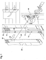
- Fig. 1 Tor shown has a total of 10 designated door leaf and a total of 20 designated door leaf.
- the door leaf comprises a plurality of door leaf elements 12, which are connected by means of hinges 14 with respect to horizontal tilt axes tilted together.
- the door leaf 20 comprises a plurality of door leaf elements 22, which are also connected by means of hinges 24 tiltable with respect to the tilt axes.
- Fig. 1 the door leaf is shown in a half open position. In this position, the door leaf and door leaf elements can not be tilted against each other, since the tilt axes do not coincide.
- the tilting axes coincide so that Torblattemia and door leaf elements can be tilted against each other.
- the in Fig. 1 Gate shown a positioning device with an adjacent to the adjacent door leaf element 22 edge of a Torblattelements 12th fixed positioning means 30 and a guide element 40 fixed to the door leaf element 12 facing edge of the door leaf element.
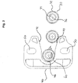
- a guide surface 42 of the guide element 40 comes into contact with contact surfaces of the positioning means 30 which can roll on the guide surface due to its rotatable mounting.
- the positioning means 30 comprises a rotatably mounted on a bearing pin 34 contact ring 32.
- the guide element 40 comprises two guide surfaces 42 and 44, of which the guide surface 42 drops ramp-shaped in the direction of the end position and the guide surface 44 rises in a ramp-shaped manner in the direction of the end position. Both the guide surface 42 and the guide surface 44 is in the direction of the end position in an approximately horizontally extending region over to enable a low-power storage of the recorded in the end position positioning means.
- the guide surfaces 42 and 44 are spaced from each other with respect to the pivot axis (not shown) and form an inlet funnel for the positioning means 30. At the side facing away from the funnel mouth of the funnel is limited by a stop surface 46, with the pivoting movement of the positioning means 30 with respect to the guide member 40th is limited.
- the guide element 40 has an approximately plate-shaped structure with two recesses 50.
- the recesses 50 serve for fastening the guide element to an edge of a door leaf element and / or a door leaf element with the aid of suitable screw bolts which pass through the recesses 50 and abut the bolt head on the plate-shaped guide element 40.
- the representation in Fig. 2 is held so that the positioning means 30 is mounted on the door leaf member, while the guide member 40 is mounted on the adjacent Torblattelement so that the positioning means 30 rolls in the course of a closing movement along the ramp-shaped guide surface 44, so as to position the positioning means in the 60th urged end position to push.
- the positioning means 30 is raised by a height h.
- the guide element 40 is embodied approximately mirror-symmetrically with respect to a mirror plane running perpendicular to the paper plane or parallel to the Kotaktringachse 36. As a result, the guide element 40 can be used at different installation positions.
- a gate according to the invention may comprise two, three or more positioning devices of the type described in US Pat Fig. 2 have shown type, which are arranged spaced apart in the direction of the pivot axis. For example, it may be thought to assign a positioning device to each of the door leaf elements arranged one above the other in the closed position.
- the invention is not limited to the embodiment explained with reference to the drawing. Rather, it is also thought to bring guide elements with only one guide surface for use.
- the positioning means can be realized in the form of a rotatably mounted in a Torblattelement and / or door leaf element bolt.
- the guide surface 42 and 44 may be performed differently arcuate as shown in the drawing.
Description
Die Erfindung betrifft ein Tor mit einem zwischen einer Schließstellung und einer Öffnungsstellung bewegbaren und eine Mehrzahl von bezüglich parallel zueinander verlaufenden Kippachsen gegeneinander verkippbaren Torblattelementen aufweisenden Torblatt, einer in dem Torblatt integrierten Tür mit einem um eine etwa senkrecht zu den Kippachsen verlaufende Schwenkachse bezüglich in Richtung der Kippachse benachbarten Torblattelementen verschwenkbaren, in seiner Schließstellung in einer Ausnehmung des Torblatts aufgenommenen und in der Schließstellung vorzugsweise in der Torblattebene angeordneten Türblatt und einer mindestens eine vorzugsweise rampenartige Führungsfläche sowie mindestens eine bei einer Schließbewegung in Anlage an die Führungsfläche gelangenden Führungsmittel aufweisenden Positionierungseinrichtung zum Positionieren eines der Schwenkachse abgewandten Randes des Türblatts bei Erreichen der Schließstellung.The invention relates to a gate with a movable between a closed position and an open position and a plurality of mutually parallel tilt axes against each other tiltable Torblattelementen having door leaf, an integrated door in the door with an approximately perpendicular to the tilt axis pivot axis with respect to in the direction of Tilting axis adjacent door leaf elements pivotable, recorded in its closed position in a recess of the door leaf and arranged in the closed position preferably in the door leaf level door leaf and at least one preferably ramp-like guide surface and at least one in a closing movement in contact with the guide surface passing guide means having positioning means for positioning one of Swivel axis facing away from the edge of the door leaf when reaching the closed position.
Tore mit einer Mehrzahl von bezüglich parallel zueinander verlaufenden Kippachsen gegeneinander verkippbaren Torblattelementen aufweisenden Torblättern werden in Form von Garagentoren und in Form von Industrietoren zum Verschließen von Durchfahrten in Garagen und Industriehallen eingesetzt. In beiden Fällen ist das Torblatt üblicherweise in der Schließstellung etwa in einer vertikalen Ebene und in der Öffnungsstellung über Kopf etwa in einer horizontalen Ebene angeordnet. Zur Führung der Torblattbewegung zwischen der Schließstellung und der Öffnungsstellung sind üblicherweise Führungsschienen mit einem etwa geradlinig und etwa parallel zum seitlichen Torblattrand in der Schließstellung verlaufenden vertikalen Abschnitt, einem weiteren etwa geradlinig und etwa parallel zum seitlichen Torblattrand in der Öffnungsstellung verlaufenden horizontalen Abschnitt und einem die beiden geradlinigen Abschnitte miteinander verbindenden bogenförmigen Abschnitt vorgesehen. Zur Ermöglichung der Torblattbewegung längs des bogenförmigen Abschnitts sind die Torblattelemente des Torblatts um senkrecht zu den Führungsschienen verlaufende Kippachsen gegeneinander verkippbar miteinander verbunden.Gates having a plurality of relative to each other extending tilt axes against each other tiltable Torblattelementen having door leaves are used in the form of garage doors and in the form of industrial gates for closing passages in garages and industrial halls. In both cases, the door leaf is usually in the closed position approximately in a vertical plane and in the open position above the head arranged approximately in a horizontal plane. To guide the Torblattbewegung between the closed position and the open position are usually guide rails with an approximately rectilinear and approximately parallel to the side Torblattrand in the closed position extending vertical section, another approximately rectilinear and approximately parallel to the side Torblattrand in the open position extending horizontal section and one the two provided rectilinear portions interconnecting arcuate portion. To enable the Torblattbewegung along the arcuate portion of the door leaf elements of the door leaf are mutually tiltable connected to each other about tilting axes extending perpendicular to the guide rails.
Falls eine Person einen mit einem derartigen Tor verschlossenen Raum verlassen will, muß das bei Industrietoren eine Breite von 5 Metern oder mehr aufweisende Torblatt als Ganzes von der Schließstellung in die Öffnungsstellung bewegt werden. Das bedeutet nicht nur eine beachtliche Erhöhung der Belastung der mechanischen Elemente des Torblatts, sondern ist auch mit einem hohen Zeitaufwand verbunden. Zur Lösung dieser Probleme wurde bereits vorgeschlagen, eine Tür mit einem um eine etwa senkrecht zu den Kippachsen und in der Schließstellung des Torblatts etwa in Schwererichtung verlaufende Schwenkachse bezüglich den benachbarten Torblattelementen verschwenkbaren Türblatt in das Torblatt zu integrieren. Eine derartige Schlupftür ermöglicht das Verlassen des mit dem Torblatt verschlossenen Raums auch ohne Öffnen des Torblatts als Ganzes. Vielmehr muß nur das in das Torblatt integrierte Türblatt durch Verschwenken in die Schwenkachse geöffnet werden. Zur Ermöglichung einer Öffnungsbewegung des Torblatts mit dem darin integrierten Türblatt besteht auch das Türblatt derartiger Konstruktionen üblicherweise aus einer Mehrzahl von bezüglich kolinear zu den Kippachsen verlaufenden Achsen gegeneinander verkippbaren Türblattelementen.If a person wants to leave a space locked with such a gate, the gate door having a width of 5 meters or more in industrial doors must be moved as a whole from the closed position to the open position. This not only means a considerable increase in the load on the mechanical elements of the door leaf, but is also associated with a high expenditure of time. To solve these problems has already been proposed to integrate a door with a pivotable about an approximately perpendicular to the tilting axes and in the closed position of the door leaf approximately in the direction of gravity pivot axis with respect to the adjacent door leaf elements door leaf in the door leaf. Such a wicket door allows leaving the closed space with the door leaf without opening the door leaf as a whole. Rather, only the integrated door leaf in the door leaf must be opened by pivoting in the pivot axis. To enable an opening movement of the door leaf with the door leaf integrated therein, the door leaf of such constructions usually consists of a plurality of with respect to collinear axes extending to the tilt axes against each other tiltable door leaf elements.
Bei diesen Konstruktionen sind also die Türblattelemente miteinander, die Torblattelemente miteinander und die Türblattelemente mit den Torblattelementen verschwenkbar verbunden. Aufgrund des in einer solchen verschwenkbaren Verbindung unvermeidbar auftretenden Spiels der gelenkigen Verbindung kann es bei solchen Konstruktionen dazu kommen, daß das Türblatt in der Öffnungsstellung bezüglich dem Torblatt etwas verkippt, so daß der den Schwenkachsen abgewandte Rand des Türblatts bzw. der untere Rand des Türblatts an der der Schwenkachse abgewandten Ecke unter Schwerkrafteinwirkung nach unten abfällt. Dadurch kann eine Schließbewegung des Türblatts behindert werden, wenn es im Verlauf der Schließbewegung aufgrund der Verkippung gegen die die Laibung für das Türblatt bildenden Torblattelemente schlägt.In these constructions, therefore, the door leaf elements with each other, the door leaf elements are connected to each other and the door leaf elements pivotally connected to the Torblattelementen. Due to the play of the articulated connection, which inevitably occurs in such a pivotable connection, the door leaf may tilt slightly in the open position with respect to the door leaf, so that the edge of the door leaf facing away from the pivot axis or the lower edge of the door leaf, respectively the pivot axis facing away from the corner falls down under gravity. As a result, a closing movement of the door leaf can be hindered if it strikes in the course of the closing movement due to the tilting against the soffit for the door leaf forming Torblattelemente.
Zur Lösung der beschriebenen Probleme wurde bereits der Einsatz von Positionierungseinrichtungen vorgeschlagen, mit denen das Türblatt im Verlauf der Schließbewegung automatisch in sein Soll-Lager geführt wird. Die bekannten Positionierungseinrichtungen weisen eine beispielsweise an einem Türblattelement, insbesondere einem schloßseitigen Türblattrand, befestigten Führungsbolzen auf, der im Verlauf der Schließbewegung des Türblatts in Anlage an eine an dem benachbarten Torblattelement vorgesehene rampenartige Führungsfläche gelangt. Diese Führungsfläche steigt in Richtung auf eine der Schließstellung des Türblatts entsprechende Endlage an. Durch die gleitende Anlage des Führungsbolzens an der Führungsfläche wird das Türblatt automatisch in der gewünschten Endlage positioniert.To solve the problems described, the use of positioning devices has already been proposed with which the door leaf in the course of the closing movement automatically guided to its target warehouse. The known positioning devices have, for example, on a door leaf element, in particular a lock-side door leaf edge, fixed guide pin, which comes in the course of the closing movement of the door leaf in abutment against a provided on the adjacent door leaf element ramp-like guide surface. This guide surface increases in the direction of a closed position of the door leaf corresponding end position. The sliding contact of the guide pin on the guide surface automatically positions the door leaf in the desired end position.
Tore mit integrierter Schlupftür sind in der
Beim Einsatz der bekannten Positionierungseinrichtungen hat es sich jedoch in vielen Fällen gezeigt, daß die Schließbewegung des Türblatts immer noch mit einem großen Kraftaufwand verbunden ist. Das führt zu einer entsprechend hohen mechanischen Belastung der Einzelelemente des mit dem Türblatt ausgestatteten Tors. Angesichts dieser Probleme im Stand der Technik liegt der Erfindung die Aufgabe zugrunde, ein Tor mit integrierter Schlupftür bereitzustellen, welches ohne übermäßigen Verschleiß die gewünschten Funktionen über einen langen Zeitraum beibehält.When using the known positioning devices, however, it has been shown in many cases that the closing movement of the door leaf is still associated with a great expenditure of force. This leads to a correspondingly high mechanical load of the individual elements of the door panel equipped with the door. In view of these problems in the prior art, the object of the invention is to provide a gate with an integrated wicket door which, without excessive wear, retains the desired functions over a long period of time.
Erfindungsgemäß wird diese Aufgabe durch eine Weiterbildung der bekannten Tore gelöst, die im Wesentlichen dadurch gekennzeichnet ist, daß das Führungsmittel eine bezüglich einer in der Schließstellung etwa parallel zu den Kippachsen verlaufende Drehachse drehbar gelagerte Kontaktfläche aufweist, mit der es in Anlage an die Führungsfläche gelangt und die zum Abrollen auf der Führungsfläche im Verlauf einer Schließbewegung des Türblatts ausgelegt ist, wobei mindestens eine Führungsfläche rampenartig mit einer Steilheit von 4 bis 20 Grad, vorzugsweise 5 bis 10 Grad bezüglich einer Horizontalebene ausgeführt ist. Diese Erfindung geht auf die überraschend einfache Erkenntnis zurück, daß der bei den herkömmlichen Schlupftüren beobachtete hohe Kraftaufwand im Verlauf der Schließbewegung weder durch ein übermäßiges Gewicht des Türblatts noch durch eine übermäßige Verkantung verursacht wird, sondern in erster Linie auf die bei der gleitenden Bewegung des Führungsbolzens längs der Führungsfläche auftretenden Gleitreibung zurückzuführen ist.According to the invention this object is achieved by a development of the known goals, which is characterized essentially in that the guide means has a relative to a in the closed position approximately parallel to the tilt axis extending axis of rotation rotatably mounted contact surface, with which it comes into contact with the guide surface and which is designed for rolling on the guide surface in the course of a closing movement of the door leaf, wherein at least one guide surface is designed like a ramp with a slope of 4 to 20 degrees, preferably 5 to 10 degrees with respect to a horizontal plane. This invention is based on the surprisingly simple knowledge that the observed in the conventional wicket doors high force in the course of the closing movement is caused either by an excessive weight of the door panel or by excessive tilting, but primarily to the sliding movement of the guide pin along the guide surface occurring sliding friction is due.
Bei der erfindungsgemäß vorgesehenen drehbaren Lagerung der Kontaktflächen wird die Gleitreibung durch eine wesentlich geringere rollende Reibung ersetzt. Das führt zu einer beachtlichen Reduzierung des für die Schließbewegung erforderlichen Kraftaufwands auch wenn das Türblatt in der Öffnungsstellung aufgrund der Schwerkrafteinwirkung und des unvermeidbaren Lagerspiels stark verkippt ist. Die geringere rollende Reibung erlaubt es auch, die Führungsfläche mit einem steileren Rampenwinkel auszustatten, um so eine stärkere Anhebung des Türblatts in die gewünschte Endlage zu bewirken, ohne daß es dadurch zu einer übermäßigen Belastung der einzelnen Komponenten des Tors kommt.In the inventively provided rotatable mounting of the contact surfaces, the sliding friction is replaced by a much lower rolling friction. This also leads to a considerable reduction of the force required for the closing movement when the door leaf is tilted strongly in the open position due to the gravitational force and the inevitable bearing clearance. The lower rolling friction also makes it possible to provide the guide surface with a steeper ramp angle, so as to bring about a greater increase of the door leaf in the desired end position, without this resulting in an excessive load on the individual components of the door.
Bei einer besonders bevorzugten Ausführungsform der Erfindung ist die Kontaktfläche durch einen drehbar gelagerten Kontaktring gebildet. Wenn das Führungsmittel einen an einem Türblattelement oder Torblattelement befestigtes Lagerelement, insbesondere Lagerbolzen aufweist, kann der Kontaktring über ein Kugel- und/oder Wälzlager bezüglich des Lagerbolzens drehbar gelagert sein. Dadurch wird eine besonders geringe rollende Reibung erreicht.In a particularly preferred embodiment of the invention, the contact surface is formed by a rotatably mounted contact ring. If the guide means has a bearing element fastened to a door leaf element or door leaf element, in particular a bearing pin, the contact ring can be rotatably supported by a ball and / or roller bearing with respect to the bearing pin. As a result, a particularly low rolling friction is achieved.
Wie vorstehend bereits angesprochen, kann die Führungsfläche in Richtung auf eine Endlage für das Führungsmittel rampenartig ansteigen und/oder fallen. Im Rahmen der Erfindung kann vorgesehen sein, daß die Führungsfläche an einem einem Türblattelement benachbarten Rand des Torblattelements angebracht ist. In diesem Fall wird eine Anhebung des Türblattelements erreicht, wenn die Führungsfläche rampenartig in Richtung auf die Endlage ansteigt. Bei anderen Ausführungsformen der Erfindung ist die Führungsfläche an einem dem benachbarten Torblattelement zugeordneten Rand eines Türblattelements angebracht. In diesem Fall wird eine Hebewirkung erreicht, wenn die Führungsfläche in Richtung auf die Endlage abfällt.As already mentioned above, the guide surface may rise and / or fall in the direction of an end position for the guide means in a ramp-like manner. In the context of the invention can be provided that the guide surface is attached to a door leaf element adjacent edge of the door leaf element. In this case, an elevation of the door leaf element is achieved when the guide surface rises like a ramp in the direction of the end position. In other embodiments of the invention, the guide surface is attached to an edge of a door leaf element associated with the adjacent door leaf element. In this case, a lifting effect is achieved when the guide surface drops towards the end position.
Bei einer besonders bevorzugten Ausführungsform der Erfindung sind zwei in Richtung der Schwenkachse voneinander beabstandete Führungsflächen vorgesehen, von denen eine in Richtung auf die Endlage rampenartig ansteigt und die andere in Richtung auf die Endlage rampenartig abfällt, derart, daß von den Führungsflächen ein trichterförmiger Einlauf für das Führungsmittel gebildet wird. In diesem Fall können mit dem Führungsmittel Verkippungen des Türblatts in beide Richtungen ausgeglichen werden. Verkippungen der unteren, der Schwenkachse abgewandten Ecke des Türblatts nach oben können beispielsweise vorkommen, wenn das Torblatt auf einem unebenen Untergrund aufläuft.In a particularly preferred embodiment of the invention, two spaced apart in the direction of the pivot axis guide surfaces are provided, one of which ramps toward the end position and the other ramps towards the end position, such that of the guide surfaces a funnel-shaped inlet for the Guide is formed. In this case, tilting of the door leaf in both directions can be compensated with the guide means. Tilting of the lower, the pivot axis facing away from the corner of the door panel upwards may occur, for example, when the door leaf runs on an uneven surface.
Die Führungsflächen werden im Sinne eines modularen Aufbaus erfindungsgemäßer Tore besonders zweckmäßig an einem an einem Türblattelement und/oder Torblattelement festlegbaren Führungselement gebildet. Das Führungselement kann dabei auch mehrteilig ausgeführt sein. Diese Ausführungsform der Erfindung ermöglicht auch eine Nachrüstung bereits montierter Tore durch Anbringen von separaten Führungselementen und Führungsmitteln an benachbarten Türblattelementen und Torblattelementen.In the sense of a modular construction of gates according to the invention, the guide surfaces are particularly expediently formed on a guide element which can be fixed to a door leaf element and / or door leaf element. The guide element can also be designed in several parts. This embodiment of the invention also makes it possible to retrofit already mounted gates by attaching separate guide elements and guide means to adjacent door leaf elements and door leaf elements.
Dabei kann eine übermäßige Lagerhaltung durch universell einsetzbare Bauteile vermieden werden, wenn das Führungselement im wesentlichen spiegelsymmetrisch bezüglich einer zwischen den Führungsflächen angeordneten Spiegelebene ausgeführt ist. Eine besonders sichere und kraftarme Positionierung des Türblatts läßt sich erreichen, wenn zwei, drei oder mehr in Richtung der Schwenkachse voneinander beabstandete Positionierungseinrichtungen vorgesehen sind. Im Rahmen der Erfindung hat es sich ohne übermäßige mechanische Beanspruchung der Bauelemente des Tores als möglich erwiesen, daß der der Schwenkachse abgewandte Rand des Türblatts bzw. eine der Schwenkachse abgewandte untere Ecke des Türblatts durch Bewegung des Positionierungsmittels bezüglich einer Führungsfläche um zwei Millimeter oder mehr anhebbar ist. Mit Blick auf die üblicherweise für die Führungsfläche zur Verfügung stehende Einbautiefe, welche durch die Dicke der Türblattelemente oder der Torblattelemente vorgegeben ist, weist mindestens eine Führungsfläche erfindungsgemäß eine rampenartig ansteigende Ebene mit einer Steilheit von 4 bis 20 Grad, vorzugsweise 5 bis 10 Grad bezüglich einer Horizontalebene auf. Ähnlich wie bei bekannten Toren hat es sich auch im Rahmen der Erfindung als zweckmäßig erwiesen, wenn mindestens eine Führungsfläche in einer Schwenkbewegung des Türblatts in die die Schließstellung begrenzende Anschlagfläche übergeht. Wie eingangs bereits erläutert, weist das Türblatt erfindungsgemäßer Tore regelmäßig eine Mehrzahl von bezüglich den Kippachsen gegeneinander verkippbare Türblattelemente auf.In this case, excessive storage can be avoided by universally applicable components, when the guide element is designed substantially mirror-symmetrically with respect to a arranged between the guide surfaces mirror plane. A particularly safe and low-force positioning of the door leaf can be achieved if two, three or more spaced in the direction of the pivot axis positioning devices are provided. In the context of the invention, it has been without excessive mechanical stress on the components of the door proved to be possible that the pivot axis remote from the edge of the door leaf or a pivot axis remote from the bottom corner of the door leaf by movement of the positioning means relative to a guide surface by two millimeters or more can be raised. With regard to the installation depth usually available for the guide surface, which is predetermined by the thickness of the door leaf elements or door leaf elements, at least one guide surface according to the invention has a ramp-like rising plane with a steepness of 4 to 20 degrees, preferably 5 to 10 degrees with respect to a Horizontal plane up. Similar to known doors, it has also proven to be expedient in the context of the invention if at least one guide surface merges in a pivoting movement of the door leaf into the stop surface delimiting the closed position. As already explained at the beginning, the door leaf according to the invention regularly has a plurality of door leaf elements which can be tilted relative to one another relative to the tilt axes.
Nachstehend wir die Erfindung unter Bezugnahme auf die Zeichnung, auf die sich hinsichtlich aller erfindungswesentlichen und in der Beschreibung nicht näher herausgestellten Einzelheiten ausdrücklich verwiesen wird, erläutert. Die Zeichnung zeigt:
-
Fig. 1 eine schematische Darstellung eines mit einer erfindungsgemäßen Positionierungseinrichtung ausgestatteten erfindungsgemäßen Tors und -
Fig. 2 eine schematische Darstellung der Positionierungsvorrichtung gemäßFig. 1 .
-
Fig. 1 a schematic representation of a equipped with a positioning device according to the invention inventive gate and -
Fig. 2 a schematic representation of the positioning device according toFig. 1 ,
Das in
Wie besonders deutlich in
Das Führungselement 40 weist einen etwa plattenförmigen Aufbau mit zwei Ausnehmungen 50 auf. Die Ausnehmungen 50 dienen zur Befestigung des Führungselements an einem Rand eines Torblattelements und/oder eines Torblattelements mit Hilfe von geeigneten Schraubbolzen, welche die Ausnehmungen 50 durchsetzen und die am Bolzenkopf an dem plattenförmigen Führungselement 40 anliegen. Die Darstellung in
An dieser Stelle wird nochmals darauf hingewiesen, daß sich der Aufbau gemäß
Ein erfindungsgemäßes Tor kann zwei, drei oder mehr Positionierungseinrichtungen der in
Die Erfindung ist nicht auf das anhand der Zeichnung erläuterte Ausführungsbeispiel eingeschränkt. Vielmehr ist auch daran gedacht, Führungselemente mit nur einer Führungsfläche zum Einsatz zu bringen. Das Positionierungsmittel kann in Form eines drehbar in einem Torblattelement und/oder Türblattelement gelagerten Bolzens verwirklicht sein. Die Führungsfläche 42 und 44 können anders als in der Zeichnung dargestellt auch bogenförmig ausgeführt sein.The invention is not limited to the embodiment explained with reference to the drawing. Rather, it is also thought to bring guide elements with only one guide surface for use. The positioning means can be realized in the form of a rotatably mounted in a Torblattelement and / or door leaf element bolt. The
Claims (12)
- A gate comprising a gate leaf (10) that can be moved between a closed position and an open position and that has a plurality of gate leaf elements (12) that can be tilted with respect to one another relative to tilt axes running parallel to one another, a door (20) integrated into the gate leaf (10) and having a door leaf (20) that can be swivelled relative to gate leaf elements (12) that are adjacent in the direction of the tilt axis about a swivel axis running perpendicular to the tilt axes, that is accommodated in a recess of the gate leaf (10) when in the closed position, and preferably disposed in the plane of the gate leaf when in the closed position, and a positioning device having at least one preferably ramp-like guide surface (42, 44) and a guide means that comes into contact with the guide surface (42, 44) during a closing movement for positioning an edge of the door leaf (20) facing away from the swivel axis upon reaching the closed position, characterised in that the guide means has a contact surface rotatably mounted relative to an axis of rotation (36) running approximately parallel to the tilt axes in the closed position, with which contact surface said guide means comes into contact with the guide surface (42, 44) and which is designed to unroll on the guide surface (42, 44) in the course of a closing movement, at least one guide surface (42, 44) being made in the manner of a ramp with a gradient of 4 to 20 degrees relative to a horizontal plane.
- The gate according to Claim 1, characterised in that the contact surface is formed by a rotatably mounted contact ring (32).
- The gate according to any of the preceding claims, characterised in that at least one guide means (30) is fastened to a gate leaf element (12) and/or to a door leaf element (22).
- The gate according to Claim 3, characterised in that the contact ring (32) is mounted rotatably by means of a ball bearing and/or a roller bearing relative to a mounting element, in particular a mounting pin (34), fastened to a door element (22) or a gate leaf element (12).
- The gate according to any of the preceding claims, characterised in that the guide surface (42, 44) rises and/or falls like a ramp towards an end position for the guide means.
- The gate according to Claim 5, characterised by two guide surfaces (42, 44) spaced apart from one another in the direction of the swivel axis, one of which rises like a ramp towards the end position and the other falls like a ramp towards the end position such that a funnel-shaped run-in for the positioning means (30) is formed by the guide surfaces (42, 44).
- The gate according to Claim 5 or 6, characterised in that the guide surfaces (42, 44) are formed by a guide element (40) that can be fixed to a door leaf element and/or a gate leaf element.
- The gate according to Claim 7, characterised in that the guide element (40) is made to be substantially mirror-symmetrical relative to a mirror plane disposed between the guide surfaces (42, 44).
- The gate according to any of the preceding claims, characterised by two, three or more positioning devices spaced apart from one another in the direction of the swivel axis.
- The gate according to any of the preceding claims, characterised in that the edge of the door leaf facing away from the swivel axis can be raised by two millimetres or more by moving the positioning means (30) relative to a guide surface (42, 44).
- The gate according to any of the preceding claims, characterised in that a guide surface (42, 44) merges into a stop surface (46) bordering the swivel movement of the door leaf into the closed position.
- The gate according to any of the preceding claims, characterised in that the door leaf has a plurality of door leaf elements (22) that can be tilted with respect to one another relative to the tilt axes.
Priority Applications (1)
| Application Number | Priority Date | Filing Date | Title |
|---|---|---|---|
| PL17196364T PL3296500T3 (en) | 2012-08-10 | 2013-06-13 | Gate |
Applications Claiming Priority (2)
| Application Number | Priority Date | Filing Date | Title |
|---|---|---|---|
| DE102012015896.3A DE102012015896A1 (en) | 2012-08-10 | 2012-08-10 | gate |
| EP13003041.4A EP2698495B1 (en) | 2012-08-10 | 2013-06-13 | Door |
Related Parent Applications (2)
| Application Number | Title | Priority Date | Filing Date |
|---|---|---|---|
| EP13003041.4A Division EP2698495B1 (en) | 2012-08-10 | 2013-06-13 | Door |
| EP13003041.4A Division-Into EP2698495B1 (en) | 2012-08-10 | 2013-06-13 | Door |
Publications (2)
| Publication Number | Publication Date |
|---|---|
| EP3296500A1 EP3296500A1 (en) | 2018-03-21 |
| EP3296500B1 true EP3296500B1 (en) | 2018-10-24 |
Family
ID=48699496
Family Applications (2)
| Application Number | Title | Priority Date | Filing Date |
|---|---|---|---|
| EP17196364.8A Active EP3296500B1 (en) | 2012-08-10 | 2013-06-13 | Gate |
| EP13003041.4A Revoked EP2698495B1 (en) | 2012-08-10 | 2013-06-13 | Door |
Family Applications After (1)
| Application Number | Title | Priority Date | Filing Date |
|---|---|---|---|
| EP13003041.4A Revoked EP2698495B1 (en) | 2012-08-10 | 2013-06-13 | Door |
Country Status (3)
| Country | Link |
|---|---|
| EP (2) | EP3296500B1 (en) |
| DE (1) | DE102012015896A1 (en) |
| PL (2) | PL3296500T3 (en) |
Cited By (1)
| Publication number | Priority date | Publication date | Assignee | Title |
|---|---|---|---|---|
| DE102020116927A1 (en) | 2020-06-26 | 2021-12-30 | Alpha Deuren International Bv | Closing element and gate with a closing element |
Families Citing this family (9)
| Publication number | Priority date | Publication date | Assignee | Title |
|---|---|---|---|---|
| DE102014009848A1 (en) | 2014-07-02 | 2016-01-07 | Hörmann KG Brockhagen | gate |
| DE102015105982A1 (en) * | 2015-04-20 | 2016-10-20 | Hettich-Heinze Gmbh & Co. Kg | Fitting for a sliding door and method for mounting a guide fitting |
| FI20170145A (en) * | 2017-03-13 | 2018-09-25 | Vak Oy | Latching mechanism for a cargo body door |
| DE202017106659U1 (en) * | 2017-11-03 | 2019-02-05 | DOCO International B.V. NL | wicket |
| CN110439412A (en) * | 2019-09-18 | 2019-11-12 | 广东永丰智威电气有限公司 | A kind of door body positioning device of power switch cabinet |
| GB2590975B (en) * | 2020-01-10 | 2023-08-23 | Profine Uk Ltd | Improvement in flush casements and device thereof |
| EP3929384A1 (en) * | 2020-06-26 | 2021-12-29 | Alpha Deuren International BV | Centering unit for a door leaf within a movable door leaf |
| DE102021108284A1 (en) * | 2021-03-31 | 2022-10-06 | Alpha Deuren International Bv | Centering unit in connection with attachment closing elements for a door leaf in a mobile door leaf |
| DE102021106140A1 (en) | 2021-03-12 | 2022-09-15 | Hörmann Kg Ichtershausen | Gate with wicket door |
Citations (13)
| Publication number | Priority date | Publication date | Assignee | Title |
|---|---|---|---|---|
| GB372919A (en) | 1931-04-17 | 1932-05-19 | George Mansell | Door support and guide means |
| US4518182A (en) | 1982-07-19 | 1985-05-21 | A & M Cousin Etablissements Cousin Freres S.A.R.L. | Electric safety lock more specially for motor vehicle doors |
| US5829197A (en) | 1995-12-02 | 1998-11-03 | Samsung Electronics Co., Ltd. | Manually actuable apparatus enabling a door to be selectively hinged at either side |
| DE20004943U1 (en) | 2000-03-17 | 2000-07-06 | Schuering Gmbh & Co Fenster Te | Locking device with mushroom-shaped pin |
| US6131337A (en) | 1998-04-22 | 2000-10-17 | Aisin Seiki Kabushiki Kaisha | Vehicle door closing apparatus |
| US6168216B1 (en) | 1997-12-25 | 2001-01-02 | Mitsui Kinzoku Kogyo Kabushiki Kaisha | Vehicle door latch device |
| DE10006765A1 (en) | 2000-02-15 | 2001-08-23 | Bosch Gmbh Robert | Motor vehicle door lock with a compact structure |
| DE10100008A1 (en) | 2001-01-02 | 2002-07-11 | Bosch Gmbh Robert | Sealed electrically operated lock assembly for motor vehicles, uses sealed box to house lock with external cam driven by shaft that passes through seal fitted to hole in cover of box |
| DE102005026026A1 (en) | 2004-06-04 | 2006-02-09 | Butzbach, Thilo | Multi panel door especially roller door has an integral wicket gate with at least one panel fitted with a static reinforcing strip to stabilise the bottom of the door structure |
| DE102005055152A1 (en) | 2005-11-18 | 2007-05-31 | Hörmann KG Amshausen | Door leaf with wicket door and multiple locking |
| EP1876317A1 (en) | 2006-07-04 | 2008-01-09 | Novoferm GmbH | Sectional door |
| EP2224082A1 (en) | 2007-11-22 | 2010-09-01 | Aisin Seiki Kabushiki Kaisha | Opening/closing device for vehicle door |
| AT11699U1 (en) | 2010-01-18 | 2011-03-15 | Guttomat Sektionaltore Gmbh | GATE, ESPECIALLY CEILING SECTOR |
Family Cites Families (2)
| Publication number | Priority date | Publication date | Assignee | Title |
|---|---|---|---|---|
| DE9113686U1 (en) * | 1991-11-04 | 1992-02-20 | Dmw Schwarze Gmbh & Co Industrietore Kg, 4800 Bielefeld, De | |
| DE20321194U1 (en) * | 2002-06-19 | 2006-04-20 | Bremet Brevetti Metecno S.P.A., Spilimbergo | Passage door for lamella doors with exchangeable sections |
-
2012
- 2012-08-10 DE DE102012015896.3A patent/DE102012015896A1/en active Pending
-
2013
- 2013-06-13 EP EP17196364.8A patent/EP3296500B1/en active Active
- 2013-06-13 EP EP13003041.4A patent/EP2698495B1/en not_active Revoked
- 2013-06-13 PL PL17196364T patent/PL3296500T3/en unknown
- 2013-06-13 PL PL13003041T patent/PL2698495T3/en unknown
Patent Citations (13)
| Publication number | Priority date | Publication date | Assignee | Title |
|---|---|---|---|---|
| GB372919A (en) | 1931-04-17 | 1932-05-19 | George Mansell | Door support and guide means |
| US4518182A (en) | 1982-07-19 | 1985-05-21 | A & M Cousin Etablissements Cousin Freres S.A.R.L. | Electric safety lock more specially for motor vehicle doors |
| US5829197A (en) | 1995-12-02 | 1998-11-03 | Samsung Electronics Co., Ltd. | Manually actuable apparatus enabling a door to be selectively hinged at either side |
| US6168216B1 (en) | 1997-12-25 | 2001-01-02 | Mitsui Kinzoku Kogyo Kabushiki Kaisha | Vehicle door latch device |
| US6131337A (en) | 1998-04-22 | 2000-10-17 | Aisin Seiki Kabushiki Kaisha | Vehicle door closing apparatus |
| DE10006765A1 (en) | 2000-02-15 | 2001-08-23 | Bosch Gmbh Robert | Motor vehicle door lock with a compact structure |
| DE20004943U1 (en) | 2000-03-17 | 2000-07-06 | Schuering Gmbh & Co Fenster Te | Locking device with mushroom-shaped pin |
| DE10100008A1 (en) | 2001-01-02 | 2002-07-11 | Bosch Gmbh Robert | Sealed electrically operated lock assembly for motor vehicles, uses sealed box to house lock with external cam driven by shaft that passes through seal fitted to hole in cover of box |
| DE102005026026A1 (en) | 2004-06-04 | 2006-02-09 | Butzbach, Thilo | Multi panel door especially roller door has an integral wicket gate with at least one panel fitted with a static reinforcing strip to stabilise the bottom of the door structure |
| DE102005055152A1 (en) | 2005-11-18 | 2007-05-31 | Hörmann KG Amshausen | Door leaf with wicket door and multiple locking |
| EP1876317A1 (en) | 2006-07-04 | 2008-01-09 | Novoferm GmbH | Sectional door |
| EP2224082A1 (en) | 2007-11-22 | 2010-09-01 | Aisin Seiki Kabushiki Kaisha | Opening/closing device for vehicle door |
| AT11699U1 (en) | 2010-01-18 | 2011-03-15 | Guttomat Sektionaltore Gmbh | GATE, ESPECIALLY CEILING SECTOR |
Non-Patent Citations (2)
| Title |
|---|
| "Alpha Deuren International auf der R+T 2012", BLUEPOOL, 2012, XP055626201 |
| "Ersatzteilübersicht Hörmann", INDUSTRIE SEKTIONALTORE BAUREIHE 40, 2014, XP055626207 |
Cited By (1)
| Publication number | Priority date | Publication date | Assignee | Title |
|---|---|---|---|---|
| DE102020116927A1 (en) | 2020-06-26 | 2021-12-30 | Alpha Deuren International Bv | Closing element and gate with a closing element |
Also Published As
| Publication number | Publication date |
|---|---|
| PL3296500T3 (en) | 2019-03-29 |
| EP2698495B1 (en) | 2018-01-31 |
| EP3296500A1 (en) | 2018-03-21 |
| EP2698495A2 (en) | 2014-02-19 |
| EP2698495A3 (en) | 2014-04-02 |
| PL2698495T3 (en) | 2018-06-29 |
| DE102012015896A1 (en) | 2014-02-13 |
Similar Documents
| Publication | Publication Date | Title |
|---|---|---|
| EP3296500B1 (en) | Gate | |
| WO2001055543A1 (en) | Sectional lifting door or folding door | |
| DE102012202986B4 (en) | Fitting for a sliding door or sliding window | |
| WO2008135071A1 (en) | Component for producing a sectional door panel and front cap therefor | |
| DE102010038084A1 (en) | Sliding rotating wall system for use in e.g. balcony glass panel swivel window system for pivoting window in guide rail, has latch in cooperation with element that is arranged in guide rail such that one carriage is stationarily fixed | |
| EP2843149B1 (en) | Skylight with opening mechanism | |
| DE202012101529U1 (en) | sliding system | |
| DE3300331C1 (en) | gate | |
| DE102016117336B3 (en) | Storage device of an elastically mounted gate leaf | |
| EP1467049B1 (en) | Door | |
| EP1630343B1 (en) | Overhead door for collective garages | |
| DE202008004731U1 (en) | Sliding door, especially for shower enclosures | |
| EP2703591A2 (en) | Sealing device for sliding windows or sliding doors | |
| EP3480407B1 (en) | Vertical pushing element | |
| AT504558B1 (en) | Side sliding | |
| DE4221083C2 (en) | Revolving door | |
| DE4439475C1 (en) | Window mechanism for slide and tilt action | |
| DE10037329A1 (en) | Sectional vertical lift door or overhead door comprises a smaller door composed of several sections that tilt relative to one another and whose tilting axis runs coaxially to the tilting axis of the larger door sections | |
| DE102005035222A1 (en) | Sliding element e.g. for windows, has lengthwise-running shifting movement with part of wall being able to open or lockable and in closed position gap opening is lockable by sealing element movable by magnetic forces | |
| EP2677100A2 (en) | Sliding door assembly | |
| DE202016106620U1 (en) | Variable defense | |
| DE202009010998U1 (en) | Driving system for horizontally movable roof studio windows | |
| DE3817911A1 (en) | Pivoting door for shut-off means in access installations | |
| DE202021102462U1 (en) | Gate system | |
| DE102004015353B3 (en) | Explosion-proof building window has pivoted window panel frames fitted with armoured glass and moved into closed position by pressure wave resulting from explosion |
Legal Events
| Date | Code | Title | Description |
|---|---|---|---|
| PUAI | Public reference made under article 153(3) epc to a published international application that has entered the european phase |
Free format text: ORIGINAL CODE: 0009012 |
|
| STAA | Information on the status of an ep patent application or granted ep patent |
Free format text: STATUS: REQUEST FOR EXAMINATION WAS MADE |
|
| 17P | Request for examination filed |
Effective date: 20171013 |
|
| AC | Divisional application: reference to earlier application |
Ref document number: 2698495 Country of ref document: EP Kind code of ref document: P |
|
| AK | Designated contracting states |
Kind code of ref document: A1 Designated state(s): AL AT BE BG CH CY CZ DE DK EE ES FI FR GB GR HR HU IE IS IT LI LT LU LV MC MK MT NL NO PL PT RO RS SE SI SK SM TR |
|
| REG | Reference to a national code |
Ref country code: DE Ref legal event code: R079 Ref document number: 502013011453 Country of ref document: DE Free format text: PREVIOUS MAIN CLASS: E06B0003480000 Ipc: E06B0003700000 |
|
| GRAP | Despatch of communication of intention to grant a patent |
Free format text: ORIGINAL CODE: EPIDOSNIGR1 |
|
| RIC1 | Information provided on ipc code assigned before grant |
Ipc: E05D 15/24 20060101ALI20180723BHEP Ipc: E06B 3/70 20060101AFI20180723BHEP |
|
| STAA | Information on the status of an ep patent application or granted ep patent |
Free format text: STATUS: GRANT OF PATENT IS INTENDED |
|
| GRAS | Grant fee paid |
Free format text: ORIGINAL CODE: EPIDOSNIGR3 |
|
| GRAA | (expected) grant |
Free format text: ORIGINAL CODE: 0009210 |
|
| STAA | Information on the status of an ep patent application or granted ep patent |
Free format text: STATUS: THE PATENT HAS BEEN GRANTED |
|
| INTG | Intention to grant announced |
Effective date: 20180830 |
|
| AC | Divisional application: reference to earlier application |
Ref document number: 2698495 Country of ref document: EP Kind code of ref document: P |
|
| AK | Designated contracting states |
Kind code of ref document: B1 Designated state(s): AL AT BE BG CH CY CZ DE DK EE ES FI FR GB GR HR HU IE IS IT LI LT LU LV MC MK MT NL NO PL PT RO RS SE SI SK SM TR |
|
| REG | Reference to a national code |
Ref country code: CH Ref legal event code: EP |
|
| REG | Reference to a national code |
Ref country code: IE Ref legal event code: FG4D Free format text: LANGUAGE OF EP DOCUMENT: GERMAN |
|
| REG | Reference to a national code |
Ref country code: AT Ref legal event code: REF Ref document number: 1056871 Country of ref document: AT Kind code of ref document: T Effective date: 20181115 |
|
| REG | Reference to a national code |
Ref country code: DE Ref legal event code: R096 Ref document number: 502013011453 Country of ref document: DE |
|
| REG | Reference to a national code |
Ref country code: NL Ref legal event code: FP |
|
| REG | Reference to a national code |
Ref country code: SE Ref legal event code: TRGR |
|
| REG | Reference to a national code |
Ref country code: LT Ref legal event code: MG4D |
|
| PG25 | Lapsed in a contracting state [announced via postgrant information from national office to epo] |
Ref country code: LV Free format text: LAPSE BECAUSE OF FAILURE TO SUBMIT A TRANSLATION OF THE DESCRIPTION OR TO PAY THE FEE WITHIN THE PRESCRIBED TIME-LIMIT Effective date: 20181024 Ref country code: HR Free format text: LAPSE BECAUSE OF FAILURE TO SUBMIT A TRANSLATION OF THE DESCRIPTION OR TO PAY THE FEE WITHIN THE PRESCRIBED TIME-LIMIT Effective date: 20181024 Ref country code: BG Free format text: LAPSE BECAUSE OF FAILURE TO SUBMIT A TRANSLATION OF THE DESCRIPTION OR TO PAY THE FEE WITHIN THE PRESCRIBED TIME-LIMIT Effective date: 20190124 Ref country code: LT Free format text: LAPSE BECAUSE OF FAILURE TO SUBMIT A TRANSLATION OF THE DESCRIPTION OR TO PAY THE FEE WITHIN THE PRESCRIBED TIME-LIMIT Effective date: 20181024 Ref country code: ES Free format text: LAPSE BECAUSE OF FAILURE TO SUBMIT A TRANSLATION OF THE DESCRIPTION OR TO PAY THE FEE WITHIN THE PRESCRIBED TIME-LIMIT Effective date: 20181024 Ref country code: FI Free format text: LAPSE BECAUSE OF FAILURE TO SUBMIT A TRANSLATION OF THE DESCRIPTION OR TO PAY THE FEE WITHIN THE PRESCRIBED TIME-LIMIT Effective date: 20181024 Ref country code: IS Free format text: LAPSE BECAUSE OF FAILURE TO SUBMIT A TRANSLATION OF THE DESCRIPTION OR TO PAY THE FEE WITHIN THE PRESCRIBED TIME-LIMIT Effective date: 20190224 Ref country code: NO Free format text: LAPSE BECAUSE OF FAILURE TO SUBMIT A TRANSLATION OF THE DESCRIPTION OR TO PAY THE FEE WITHIN THE PRESCRIBED TIME-LIMIT Effective date: 20190124 |
|
| PG25 | Lapsed in a contracting state [announced via postgrant information from national office to epo] |
Ref country code: RS Free format text: LAPSE BECAUSE OF FAILURE TO SUBMIT A TRANSLATION OF THE DESCRIPTION OR TO PAY THE FEE WITHIN THE PRESCRIBED TIME-LIMIT Effective date: 20181024 Ref country code: GR Free format text: LAPSE BECAUSE OF FAILURE TO SUBMIT A TRANSLATION OF THE DESCRIPTION OR TO PAY THE FEE WITHIN THE PRESCRIBED TIME-LIMIT Effective date: 20190125 Ref country code: AL Free format text: LAPSE BECAUSE OF FAILURE TO SUBMIT A TRANSLATION OF THE DESCRIPTION OR TO PAY THE FEE WITHIN THE PRESCRIBED TIME-LIMIT Effective date: 20181024 Ref country code: PT Free format text: LAPSE BECAUSE OF FAILURE TO SUBMIT A TRANSLATION OF THE DESCRIPTION OR TO PAY THE FEE WITHIN THE PRESCRIBED TIME-LIMIT Effective date: 20190224 |
|
| REG | Reference to a national code |
Ref country code: DE Ref legal event code: R026 Ref document number: 502013011453 Country of ref document: DE |
|
| PG25 | Lapsed in a contracting state [announced via postgrant information from national office to epo] |
Ref country code: DK Free format text: LAPSE BECAUSE OF FAILURE TO SUBMIT A TRANSLATION OF THE DESCRIPTION OR TO PAY THE FEE WITHIN THE PRESCRIBED TIME-LIMIT Effective date: 20181024 |
|
| PLBI | Opposition filed |
Free format text: ORIGINAL CODE: 0009260 |
|
| PLAX | Notice of opposition and request to file observation + time limit sent |
Free format text: ORIGINAL CODE: EPIDOSNOBS2 |
|
| PG25 | Lapsed in a contracting state [announced via postgrant information from national office to epo] |
Ref country code: RO Free format text: LAPSE BECAUSE OF FAILURE TO SUBMIT A TRANSLATION OF THE DESCRIPTION OR TO PAY THE FEE WITHIN THE PRESCRIBED TIME-LIMIT Effective date: 20181024 Ref country code: SK Free format text: LAPSE BECAUSE OF FAILURE TO SUBMIT A TRANSLATION OF THE DESCRIPTION OR TO PAY THE FEE WITHIN THE PRESCRIBED TIME-LIMIT Effective date: 20181024 Ref country code: SM Free format text: LAPSE BECAUSE OF FAILURE TO SUBMIT A TRANSLATION OF THE DESCRIPTION OR TO PAY THE FEE WITHIN THE PRESCRIBED TIME-LIMIT Effective date: 20181024 Ref country code: EE Free format text: LAPSE BECAUSE OF FAILURE TO SUBMIT A TRANSLATION OF THE DESCRIPTION OR TO PAY THE FEE WITHIN THE PRESCRIBED TIME-LIMIT Effective date: 20181024 |
|
| 26 | Opposition filed |
Opponent name: ALPHA DEUREN INTERNATIONAL BV Effective date: 20190724 |
|
| PLBB | Reply of patent proprietor to notice(s) of opposition received |
Free format text: ORIGINAL CODE: EPIDOSNOBS3 |
|
| PG25 | Lapsed in a contracting state [announced via postgrant information from national office to epo] |
Ref country code: MC Free format text: LAPSE BECAUSE OF FAILURE TO SUBMIT A TRANSLATION OF THE DESCRIPTION OR TO PAY THE FEE WITHIN THE PRESCRIBED TIME-LIMIT Effective date: 20181024 |
|
| REG | Reference to a national code |
Ref country code: CH Ref legal event code: PL |
|
| GBPC | Gb: european patent ceased through non-payment of renewal fee |
Effective date: 20190613 |
|
| REG | Reference to a national code |
Ref country code: BE Ref legal event code: MM Effective date: 20190630 |
|
| PG25 | Lapsed in a contracting state [announced via postgrant information from national office to epo] |
Ref country code: TR Free format text: LAPSE BECAUSE OF FAILURE TO SUBMIT A TRANSLATION OF THE DESCRIPTION OR TO PAY THE FEE WITHIN THE PRESCRIBED TIME-LIMIT Effective date: 20181024 |
|
| PG25 | Lapsed in a contracting state [announced via postgrant information from national office to epo] |
Ref country code: GB Free format text: LAPSE BECAUSE OF NON-PAYMENT OF DUE FEES Effective date: 20190613 Ref country code: IE Free format text: LAPSE BECAUSE OF NON-PAYMENT OF DUE FEES Effective date: 20190613 |
|
| PG25 | Lapsed in a contracting state [announced via postgrant information from national office to epo] |
Ref country code: LI Free format text: LAPSE BECAUSE OF NON-PAYMENT OF DUE FEES Effective date: 20190630 Ref country code: LU Free format text: LAPSE BECAUSE OF NON-PAYMENT OF DUE FEES Effective date: 20190613 Ref country code: CH Free format text: LAPSE BECAUSE OF NON-PAYMENT OF DUE FEES Effective date: 20190630 Ref country code: BE Free format text: LAPSE BECAUSE OF NON-PAYMENT OF DUE FEES Effective date: 20190630 |
|
| REG | Reference to a national code |
Ref country code: AT Ref legal event code: MM01 Ref document number: 1056871 Country of ref document: AT Kind code of ref document: T Effective date: 20190613 |
|
| PG25 | Lapsed in a contracting state [announced via postgrant information from national office to epo] |
Ref country code: AT Free format text: LAPSE BECAUSE OF NON-PAYMENT OF DUE FEES Effective date: 20190613 |
|
| PG25 | Lapsed in a contracting state [announced via postgrant information from national office to epo] |
Ref country code: CY Free format text: LAPSE BECAUSE OF FAILURE TO SUBMIT A TRANSLATION OF THE DESCRIPTION OR TO PAY THE FEE WITHIN THE PRESCRIBED TIME-LIMIT Effective date: 20181024 |
|
| PG25 | Lapsed in a contracting state [announced via postgrant information from national office to epo] |
Ref country code: MT Free format text: LAPSE BECAUSE OF FAILURE TO SUBMIT A TRANSLATION OF THE DESCRIPTION OR TO PAY THE FEE WITHIN THE PRESCRIBED TIME-LIMIT Effective date: 20181024 Ref country code: HU Free format text: LAPSE BECAUSE OF FAILURE TO SUBMIT A TRANSLATION OF THE DESCRIPTION OR TO PAY THE FEE WITHIN THE PRESCRIBED TIME-LIMIT; INVALID AB INITIO Effective date: 20130613 |
|
| PG25 | Lapsed in a contracting state [announced via postgrant information from national office to epo] |
Ref country code: SI Free format text: LAPSE BECAUSE OF FAILURE TO SUBMIT A TRANSLATION OF THE DESCRIPTION OR TO PAY THE FEE WITHIN THE PRESCRIBED TIME-LIMIT Effective date: 20181024 |
|
| PG25 | Lapsed in a contracting state [announced via postgrant information from national office to epo] |
Ref country code: MK Free format text: LAPSE BECAUSE OF FAILURE TO SUBMIT A TRANSLATION OF THE DESCRIPTION OR TO PAY THE FEE WITHIN THE PRESCRIBED TIME-LIMIT Effective date: 20181024 |
|
| PGFP | Annual fee paid to national office [announced via postgrant information from national office to epo] |
Ref country code: IT Payment date: 20220630 Year of fee payment: 10 |
|
| PGFP | Annual fee paid to national office [announced via postgrant information from national office to epo] |
Ref country code: NL Payment date: 20230620 Year of fee payment: 11 Ref country code: FR Payment date: 20230620 Year of fee payment: 11 Ref country code: DE Payment date: 20230620 Year of fee payment: 11 Ref country code: CZ Payment date: 20230531 Year of fee payment: 11 |
|
| PGFP | Annual fee paid to national office [announced via postgrant information from national office to epo] |
Ref country code: SE Payment date: 20230622 Year of fee payment: 11 Ref country code: PL Payment date: 20230531 Year of fee payment: 11 |
|
| RDAF | Communication despatched that patent is revoked |
Free format text: ORIGINAL CODE: EPIDOSNREV1 |