EP3296014B1 - Partikelkontrollverfahren - Google Patents
Partikelkontrollverfahren Download PDFInfo
- Publication number
- EP3296014B1 EP3296014B1 EP16792693.0A EP16792693A EP3296014B1 EP 3296014 B1 EP3296014 B1 EP 3296014B1 EP 16792693 A EP16792693 A EP 16792693A EP 3296014 B1 EP3296014 B1 EP 3296014B1
- Authority
- EP
- European Patent Office
- Prior art keywords
- board
- oscillation
- particle
- flow
- air flow
- Prior art date
- Legal status (The legal status is an assumption and is not a legal conclusion. Google has not performed a legal analysis and makes no representation as to the accuracy of the status listed.)
- Active
Links
Images


Classifications
-
- B—PERFORMING OPERATIONS; TRANSPORTING
- B01—PHYSICAL OR CHEMICAL PROCESSES OR APPARATUS IN GENERAL
- B01J—CHEMICAL OR PHYSICAL PROCESSES, e.g. CATALYSIS OR COLLOID CHEMISTRY; THEIR RELEVANT APPARATUS
- B01J19/00—Chemical, physical or physico-chemical processes in general; Their relevant apparatus
- B01J19/08—Processes employing the direct application of electric or wave energy, or particle radiation; Apparatus therefor
- B01J19/10—Processes employing the direct application of electric or wave energy, or particle radiation; Apparatus therefor employing sonic or ultrasonic vibrations
-
- B—PERFORMING OPERATIONS; TRANSPORTING
- B01—PHYSICAL OR CHEMICAL PROCESSES OR APPARATUS IN GENERAL
- B01D—SEPARATION
- B01D49/00—Separating dispersed particles from gases, air or vapours by other methods
- B01D49/006—Separating dispersed particles from gases, air or vapours by other methods by sonic or ultrasonic techniques
-
- B—PERFORMING OPERATIONS; TRANSPORTING
- B01—PHYSICAL OR CHEMICAL PROCESSES OR APPARATUS IN GENERAL
- B01J—CHEMICAL OR PHYSICAL PROCESSES, e.g. CATALYSIS OR COLLOID CHEMISTRY; THEIR RELEVANT APPARATUS
- B01J19/00—Chemical, physical or physico-chemical processes in general; Their relevant apparatus
- B01J19/0006—Controlling or regulating processes
-
- B—PERFORMING OPERATIONS; TRANSPORTING
- B03—SEPARATION OF SOLID MATERIALS USING LIQUIDS OR USING PNEUMATIC TABLES OR JIGS; MAGNETIC OR ELECTROSTATIC SEPARATION OF SOLID MATERIALS FROM SOLID MATERIALS OR FLUIDS; SEPARATION BY HIGH-VOLTAGE ELECTRIC FIELDS
- B03C—MAGNETIC OR ELECTROSTATIC SEPARATION OF SOLID MATERIALS FROM SOLID MATERIALS OR FLUIDS; SEPARATION BY HIGH-VOLTAGE ELECTRIC FIELDS
- B03C3/00—Separating dispersed particles from gases or vapour, e.g. air, by electrostatic effect
- B03C3/34—Constructional details or accessories or operation thereof
- B03C3/36—Controlling flow of gases or vapour
-
- F—MECHANICAL ENGINEERING; LIGHTING; HEATING; WEAPONS; BLASTING
- F24—HEATING; RANGES; VENTILATING
- F24F—AIR-CONDITIONING; AIR-HUMIDIFICATION; VENTILATION; USE OF AIR CURRENTS FOR SCREENING
- F24F3/00—Air-conditioning systems in which conditioned primary air is supplied from one or more central stations to distributing units in the rooms or spaces where it may receive secondary treatment; Apparatus specially designed for such systems
- F24F3/12—Air-conditioning systems in which conditioned primary air is supplied from one or more central stations to distributing units in the rooms or spaces where it may receive secondary treatment; Apparatus specially designed for such systems characterised by the treatment of the air otherwise than by heating and cooling
- F24F3/16—Air-conditioning systems in which conditioned primary air is supplied from one or more central stations to distributing units in the rooms or spaces where it may receive secondary treatment; Apparatus specially designed for such systems characterised by the treatment of the air otherwise than by heating and cooling by purification, e.g. by filtering; by sterilisation; by ozonisation
- F24F3/167—Clean rooms, i.e. enclosed spaces in which a uniform flow of filtered air is distributed
-
- G—PHYSICS
- G01—MEASURING; TESTING
- G01N—INVESTIGATING OR ANALYSING MATERIALS BY DETERMINING THEIR CHEMICAL OR PHYSICAL PROPERTIES
- G01N15/00—Investigating characteristics of particles; Investigating permeability, pore-volume or surface-area of porous materials
- G01N15/06—Investigating concentration of particle suspensions
-
- G—PHYSICS
- G01—MEASURING; TESTING
- G01N—INVESTIGATING OR ANALYSING MATERIALS BY DETERMINING THEIR CHEMICAL OR PHYSICAL PROPERTIES
- G01N15/00—Investigating characteristics of particles; Investigating permeability, pore-volume or surface-area of porous materials
- G01N15/10—Investigating individual particles
- G01N15/14—Optical investigation techniques, e.g. flow cytometry
-
- G—PHYSICS
- G01—MEASURING; TESTING
- G01N—INVESTIGATING OR ANALYSING MATERIALS BY DETERMINING THEIR CHEMICAL OR PHYSICAL PROPERTIES
- G01N1/00—Sampling; Preparing specimens for investigation
- G01N2001/002—Devices for supplying or distributing samples to an analysing apparatus
-
- G—PHYSICS
- G01—MEASURING; TESTING
- G01N—INVESTIGATING OR ANALYSING MATERIALS BY DETERMINING THEIR CHEMICAL OR PHYSICAL PROPERTIES
- G01N15/00—Investigating characteristics of particles; Investigating permeability, pore-volume or surface-area of porous materials
- G01N2015/0042—Investigating dispersion of solids
- G01N2015/0046—Investigating dispersion of solids in gas, e.g. smoke
-
- G—PHYSICS
- G01—MEASURING; TESTING
- G01N—INVESTIGATING OR ANALYSING MATERIALS BY DETERMINING THEIR CHEMICAL OR PHYSICAL PROPERTIES
- G01N15/00—Investigating characteristics of particles; Investigating permeability, pore-volume or surface-area of porous materials
- G01N15/01—Investigating characteristics of particles; Investigating permeability, pore-volume or surface-area of porous materials specially adapted for biological cells, e.g. blood cells
- G01N2015/019—Biological contaminants; Fouling
-
- G—PHYSICS
- G01—MEASURING; TESTING
- G01N—INVESTIGATING OR ANALYSING MATERIALS BY DETERMINING THEIR CHEMICAL OR PHYSICAL PROPERTIES
- G01N15/00—Investigating characteristics of particles; Investigating permeability, pore-volume or surface-area of porous materials
- G01N15/10—Investigating individual particles
- G01N15/14—Optical investigation techniques, e.g. flow cytometry
- G01N15/1404—Handling flow, e.g. hydrodynamic focusing
- G01N2015/1415—Control of particle position
-
- G—PHYSICS
- G01—MEASURING; TESTING
- G01N—INVESTIGATING OR ANALYSING MATERIALS BY DETERMINING THEIR CHEMICAL OR PHYSICAL PROPERTIES
- G01N15/00—Investigating characteristics of particles; Investigating permeability, pore-volume or surface-area of porous materials
- G01N15/10—Investigating individual particles
- G01N15/14—Optical investigation techniques, e.g. flow cytometry
- G01N15/1404—Handling flow, e.g. hydrodynamic focusing
- G01N2015/142—Acoustic or ultrasonic focussing
Definitions
- the present invention relates to a particle control method used in a clean environment such as a clean room, an isolator device and the like. More particularly, the present invention relates to a particle control method for controlling movement of an extremely small quantity of floating particles or bacteria contained in this particle in these clean environments.
- a work performed in a clean atmosphere such as a work at a manufacturing stage of semiconductors or electronic components or in a work at a manufacturing stage of pharmaceutical products
- the works are performed in a clean work environment in which an inside is kept in a dust-free/sterile state so that contaminants do not enter from an external environment.
- clean rooms are generally used.
- a worker wearing a dust-free clothes performs a work.
- a work is performed by constructing a more highly clean zone in the clean room.
- RABS restricted-access barrier system
- RABS restricted-access barrier system
- a zone surrounded by wall surfaces with a lower part open is provided in a part of the clean room, and a laminar flow (hereinafter referred to as a "laminar flow") of clean air in unidirectional air flow flowing from an upper side to a lower side is made to flow therein and strict access restriction is set for workers.
- a worker performs a work inside through a glove or half-suit provided on the wall surface.
- an isolator device is used as another method constituting the highly clean zone. With this isolator device, a chamber sealed from an external environment is used, and a worker performs a work from an outside of this chamber through the glove or half-suit.
- the laminar flow flows to the lower side from a clean air supply device provided on the upper side through an HEPA filter or the like.
- a clean zone in a highly dust-free/sterile state can be ensured.
- Grade A Guidance on the Manufacture of Sterile Pharmaceutical Products by Ministry of Health, Labour and Welfare
- particles each having a grain size of 0.5 um or more hereinafter, referred to as a "particle" are contained up to 3520 particles/m 3 as an upper limit. These particles descend from the upper side to the lower side though the clean zone on the stream of the laminar flow. Moreover, these particles also contain floating bacteria in the air.
- a filling work of pharmaceutical products or the like is performed, for example.
- containers such as vials whose outer surfaces and insides are sterilized are conveyed to a filling machine while traveling along a conveyer or a guider. Then, the container filled with the pharmaceutical products is sealed, whereby sterile filling is completed.
- the container before filling is traveling toward the filing machine through the clean zone with its opening portion (filling port) directed upward, and it is likely that the extremely small quantity of particles (including floating bacteria) descending on the stream of the laminar flow are mixed into the container before filling.
- Patent Literature 1 Japanese Patent Laid-Open No. 2003-104320
- the dust-free/sterile state inside the RABS or isolator device is monitored by a particle counter or a flowing bacteria counter.
- These counters suction a certain amount of air in the clean zone as a sample through a capturing port and detect the particles or floating bacteria in it by an optical measuring instrument or the like.
- the floating bacteria counter using the optical measuring instrument can drastically improve work efficiency as Rapid Microbiological Methods (RMM) as compared with a prior-art culturing method.
- RMM Rapid Microbiological Methods
- JPH11325530A discloses a method for directing a flow of air and particles using acoustic waves.
- the present invention has an object to provide a particle control method which can prevent the extremely small quantity of particles descending on the stream of the laminar flow in the clean zone through which the laminar flow flows as in the RABS or isolator device from descending to a specific position or can guide it so as to descend to the specific position by controlling the movement of the particles in order to solve the aforementioned problem.
- the inventors have found that movement of the extremely small quantity of particles descending on the stream of the laminar flow can be controlled by prompting ultrasonic vibration of an oscillation board disposed in the clean zone through which the laminar flow flows as the result of keen examination and completed the present invention.
- a particle control method according to the present invention is, according to description in claim 1, characterized in that
- the present invention is, according to description in claim 2, the particle control method described in claim 1, characterized in that a distance separating away from the board surface is changed by changing an output of the ultrasonic vibration of the oscillation board, and the particle descent position is controlled in an arbitrary direction.
- the present invention is, according to description in claim 3, the particle control method described in claim 1 or 2, being
- the present invention is, according to description in claim 4, a particle measuring method, characterized in that
- the present invention is, according to description in claim 5, a particle measuring method, characterized in that
- the present invention is, according to description in claim 6, the particle measuring method described in claim 4 or 5, characterized in that by relatively changing an output of the ultrasonic vibration of each of the oscillation boards, the position of the node of the standing wave field or a position of the focal point of the ultrasonic wave is changed so that the particle descent position is controlled to move in an arbitrary direction.
- the board surface of the oscillation board is disposed on one plane alone which is substantially in parallel with the flow direction of the unidirectional air flow from the upper side toward the lower side in the work chamber. Then, this oscillation board is subjected to ultrasonic vibration so as to generate an acoustic flow by the ultrasonic wave.
- This acoustic flow is generated in the perpendicular direction from the board surface of the oscillation board and is generated in the direction crossing the flow direction of the unidirectional air flow.
- the acoustic flow generated as above gives a pressing force by the acoustic radiation pressure to the particles made to flow by the unidirectional air flow and descending from the upper side toward the lower side. As a result, the descent position of the particles can be controlled in the direction away from the board surface of the oscillation board.
- the output of the ultrasonic vibration of the oscillation board may be changed.
- the distance of the particles away from the board surface is changed, and the descent position can be controlled to an arbitrary direction.
- the board surface of the oscillation board is disposed substantially in parallel with the traveling direction of the plurality of containers traveling continuously in the clean zone. Subsequently, this oscillation board is subjected to the ultrasonic vibration so as to generate the acoustic flow by the ultrasonic wave, and the pressing force by the acoustic radiation pressure is given to the particles. As a result, even if the opening portions of the plurality of traveling containers are directed upward, control can be executed so that the descending particles are not mixed into the container.
- a pair of oscillation board and reflection board is disposed so that their board surfaces are faced with each other substantially in parallel with the flow direction of the unidirectional air flow from the upper side toward the lower side in the work chamber.
- the oscillation board is vibrated by the ultrasonic wave so as to generate the standing wave field by the ultrasonic wave.
- This standing wave field is generated in the perpendicular direction from the board surfaces of the oscillation board and the reflection board and is generated in the direction crossing the flow direction of the unidirectional air flow.
- a node of the standing wave field is formed by sound pressure distribution, and the particles descending from the upper side toward the lower side are guided in the direction of the nodes of the standing wave field.
- the descent position of the particles can be controlled to below the position of the node of the standing wave field.
- two oscillation boards may be used.
- two pairs of, that is, four units of oscillation boards are disposed with the board surfaces of each pair faced with each other, for example, substantially in parallel with the flow direction of the unidirectional air flow flowing from the upper side toward the lower side in the work chamber.
- these oscillation boards are subjected to ultrasonic vibration so as to generate an ultrasonic focal point.
- This ultrasonic focal point is generated in the perpendicular direction from the board surface of the oscillation board and is generated in the direction crossing the flow direction of the unidirectional air flow.
- the particles descending from the upper side toward the lower side are guided in the direction of this ultrasonic focal point.
- the descent position of the particles can be controlled to below the position of the ultrasonic focal point.
- three or more pairs of oscillation boards may be disposed in plural pairs with angles changed in the horizontal direction.
- an output of the ultrasonic vibration of each oscillation board may be relatively changed.
- the position of the node of the standing wave field or the position of the ultrasonic focal point is changed, and the descent position of the particles can be controlled to an arbitrary direction.
- a capturing port of the particle counter or the floating bacteria counter for measuring the quantity of the particles descending through the clean zone or of the floating bacteria contained in them is disposed below the position of the node of the standing wave field or below the position of the ultrasonic focal point.
- each of the oscillation boards is subjected to the ultrasonic vibration so as to generate the node of the standing wave field or the ultrasonic focal point and the particles or the floating bacteria contained in them are guided to the node of the standing wave field or the ultrasonic focal point.
- control can be executed such that the particles descending linearly through the clean zone or the floating bacteria contained in them can be efficiently captured through the capturing port.
- the particle control method which can prevent descent at a specific position or can guide it so as to descend to the specific position can be provided.
- This first embodiment describes a particle control method in a state where a filling device of pharmaceutical products is disposed inside (clean zone) of an isolator device maintained at Grade A.
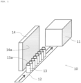
- Fig. 1 is a schematic perspective view illustrating a positional relationship between an oscillation board and a container for filling in a clean zone in this first embodiment.
- an inner wall surface of the isolator device constituting the clean zone is omitted.
- a filing device 11 of pharmaceutical products is disposed, and a conveyer 12 travels toward this filling device 11.
- a plurality of containers for filling (vial bottles) 13 before filling of the pharmaceutical products are arrayed in one row and travel in a direction of the filling device 11.
- an opening portion 13a through which the pharmaceutical products are to be filled is provided above the container for filling 13 before filling.
- the container for filling 13 filled with the pharmaceutical products in the filling device 11 is sealed after that.
- the filling device 11 disposed in the clean zone 10 is a general-purpose type device and can handle containers having various shapes. Moreover, by changing the filling device 11 to another model, a pharmaceutical filling process using diversified types of pharmaceuticals including liquid, powder, and particles and containers having various shapes corresponding to them can be set.
- the dust-free/sterile state of the clean zone 10 is maintained at Grade A required for manufacture of pharmaceutical products and the like.
- an isolator device is used, and air suctioned by an air-feeding blower is purified by an HEPA filter of an air-feeding filter unit and forms a laminar flow going from an upper side toward a lower side in the clean zone 10.
- the air on the lower side in the clean zone 10 is suctioned and discharged by an air-discharging blower through an outlet and an outlet filter.
- Fig. 1 it is likely that the particles (including the floating bacteria) descending linearly from the upper side toward the lower side are mixed in the containers for filling 13 arrayed in one row and traveling on the conveyer 12 through the opening portions 13a.
- This first embodiment has an object to exclude the particles (including the floating bacteria) to be mixed in the container for filling 13 through the opening portion 13a as above.
- an oscillation board 14 is provided on the side of the containers for filling 13 arrayed in one row.
- a board surface (oscillation surface) 14a of this oscillation board 14 is disposed substantially in parallel with a direction of the stream of the laminar flow (not shown) going from the upper side toward the lower side in the clean zone 10.
- this board surface 14a is disposed in parallel with a traveling direction (a direction from lower left to upper right in illustration) of the plurality of containers for filing 13 arrayed in one row.
- this board surface 14a is provided having a certain area in an upper direction and a width direction from the plurality of containers for filling 13 arrayed in one row.
- a lower end portion of this board surface 14a is preferably provided at least from a position faced with the opening portion 13a to the lower side.
- the oscillation board 14 will be described.
- the oscillation board is not particularly limited as long as it has a board surface vibrated by ultrasonic wave and may be a plate-shaped oscillation board in which one or a plurality of piezoelectric vibrators which are ultrasonic vibrators are connected. Moreover, it may be a transducer in which the ultrasonic vibrators are two-dimensionally arrayed in a lattice state or the like or may be a speaker or the like corresponding to an ultrasonic zone. A frequency and an output of the generated ultrasonic wave only need to be within a range which can move the particles in the clean zone, and the frequency and the output may be variably operated.
- an oscillation board in which a Langevin type vibrator is fixed to a stainless plate having a certain area is used.
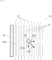
- Fig. 2 is a schematic plan view of the oscillation board 14 in the clean zone 10 in Fig. 1 when seen from above.
- the inner wall surface of the isolator device, the filing device 11, the conveyer 12, and the container for filling 13 are omitted.
- an acoustic flow 15 advancing in the air is generated in a perpendicular direction (right direction in illustration) from the board surface 14a.
- a force pressing this particle 16 in a direction where the acoustic flow 15 flows (acoustic radiation pressure 15a) is generated.
- the acoustic radiation pressure 15a pushes the particle 16 in a direction (right direction in illustration) away from the board surface 14a of the oscillation board 14.
- Fig. 2 since the particle 16 is seen from an upstream side toward a downstream side of the laminar flow, an action of the laminar flow is not illustrated.
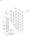
- Fig. 3 is a schematic side view of the oscillation board 14 in the clean zone 10 in Fig. 1 when seen from a lateral direction.
- the inner wall surface of the isolator device, the filling device 11, the conveyer 12, and the container for filling 13 are omitted.
- the oscillation board 14 when the oscillation board 14 is vibrated by ultrasonic wave, the acoustic flow 15 advancing in the air in the perpendicular direction (right direction in illustration) from the board surface 14a is generated.
- the acoustic radiation pressure 15a of this acoustic flow 15 acts on the particle 16 and pushes the particle 16 in the direction (right direction in illustration) away from the board surface 14a of the oscillation board 14.
- the laminar flow 17 traveling from the upper side toward the lower side flows through the clean zone 10.
- a pressing force (hereinafter referred to as a "fluid pressure 17a) by the stream of this laminar flow 17 acts on the particle 16 and pushes the particle 16 in a downstream direction (lower direction in illustration) of the laminar flow 17.
- the particle 16 in the clean zone 10 is pushed by actions of both the acoustic radiation pressure 15a by the oscillation board 14 and the fluid pressure 17a by the laminar flow 17 in a direction (lower right direction in illustration) of their resultant force 18.
- Fig. 4 is a schematic side view illustrating a positional relationship among the oscillation board, the container for filing, and the particle in the clean zone in Fig. 1 .
- the inner wall surface of the isolator device, the filling device 11, and the acoustic flow 15 are omitted.
- the container for filling 13 is placed on the conveyer 12 traveling toward the filing device (not shown) in the clean zone 10. This container for filling 13 is in a state before the pharmaceutical product is filled, and its upper part is the opening portion 13a.
- the oscillation board 14 is provided on the side of the container for filling 13.
- a side surface of the oscillation board 14 is drawn.
- the board surface 14a of this oscillation board 14 is disposed substantially in parallel with a direction of the stream of the laminar flow 17 traveling from the upper side toward the lower side in the clean zone 10.
- this board surface 14a is disposed in parallel with the traveling direction (direction perpendicular to the figure) of the plurality of containers for filling 13 arrayed in one row.
- this board surface 14a is provided having a certain area in the upper direction (vertical direction in the figure) and a width direction (direction perpendicular to the figure) of the plurality of containers for filing 13 arrayed in one row. Moreover, the lower end portion of this board surface 14a is provided to below the position faced with the opening portion 13a of the container for filling 13.
- the particle 16 receives the action of the fluid pressure 17a of the laminar flow 17 and descends linearly.
- the particle 16 receives the action of the acoustic radiation pressure 15a (not shown) by the oscillation board 14 together with the action of the fluid pressure 17a of the laminar flow 17 and descends in the direction (lower right direction in illustration) of their resultant force 18.
- the extremely small quantity of the particles (including the floating bacteria) present in the purified air at Grade A are not mixed in the container for filling 13 through the opening portion 13a.
- the particle control method which prevents particles from descending to a specific position such as the opening portion of the container for filling can be provided.
- the particle counter is also called a particle measuring instrument and refers to a measuring instrument for counting dusts, particles, impurities and the like in the air.
- sample air sampled from the capturing port disposed in the clean zone is usually irradiated with a laser beam, and a size and the number of particles are measured from its light scattering intensity.
- the laminar flow flows through the clean zone, and there is an extremely small quantity of particles descending linearly on the laminar flow from the upper side toward the lower side in the clean zone in the clean air supplied into the clean zone through the HEPA filter.
- the capturing port of the particle counter is opened with an extremely limited area on a downstream zone of the laminar flow. Therefore, by means of linear descent of the particles, the air supplied from immediately above the capturing port occupies the most of the sample air sampled from the capturing port. As a result, accurate measurement of cleanliness of the entire clean zone is difficult.
- this second embodiment has an object to control movement of an extremely small quantity of particles linearly descending through the clean zone and to collect most of them at the capturing port of the particle counter for sampling. As a result, the cleanliness of the entire clean zone maintained at Grade A can be accurately grasped.
- a pair of oscillation board and reflection board with their board surfaces faced with each other is disposed substantially in parallel with a flow direction of the laminar flow flowing from the upper side toward the lower side in the clean zone.
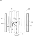
- Fig. 5 is a schematic plan view of a positional relationship between an oscillation board 21 and a reflection board 22 disposed in the clean zone 20 in this second embodiment when seen from above.
- the inner wall surface of the isolator device and the capturing port of the particle counter are omitted.
- the oscillation board 21 and the reflection board 22 are disposed in a state with their board surfaces opposed with each other.
- the oscillation board used in this second embodiment is not particularly limited and similarly to the first embodiment, it may be a plate-shaped oscillation board in which one or a plurality of piezoelectric vibrators which are ultrasonic vibrators are connected. Moreover, it may be a transducer in which the ultrasonic vibrators are two-dimensionally arrayed in a lattice state or the like or may be a speaker or the like corresponding to an ultrasonic zone. A frequency and an output of the generated ultrasonic wave only need to be within a range which can move the particles in the clean zone, and the frequency and the output may be variably operated.
- an oscillation board in which a Langevin type vibrator is fixed to a stainless plate having a certain area is used.
- a stainless plate having the same area as that of the oscillation board is used.
- a standing wave field 23 by the ultrasonic wave is generated between a board surface 21a of the oscillation board 21 and a board surface 22a of the reflection board 22 faced with each other in the perpendicular direction from each of the board surfaces and in a direction crossing the flow direction of the laminar flow.
- This standing wave field 23 is in a state obtained when an acoustic flow emitted perpendicularly from the oscillation board 21 to its board surface 21a hits and is reflected by the board surface 22a of the reflection board 22, an incident wave and a reflective wave are overlapped, and the wave does not move.
- the standing wave field 23 having a 3/4 wavelength is generated between the board surface 21a of the oscillation board 21 and the board surface 22a of the reflection board 22.
- the wavelength is ⁇
- a half wavelength ⁇ /2 is illustrated.
- Fig. 6 is a schematic side view of the oscillation board 21 and the reflection board 22 in the clean zone 20 in Fig. 5 when seen from a lateral direction.
- the inner wall surface of the isolator device is omitted.
- a capturing port 26a of the particle counter 26 is illustrated on the downstream side of a laminar flow 27.
- the oscillation board 21 is subjected to ultrasonic vibration, the standing wave field 23 is generated between the oscillation board 21 and the reflection board 22 as described above, and the particle 25 receives the guiding pressure 24a to the direction of the node 24 of the standing wave field 23.
- the laminar flow 27 flows through the clean zone 20 from the upper side toward the lower side.
- a pressing force (hereinafter referred to as a "fluid pressure 27a") by the flow of this laminar flow 27 acts on the particle 25 and pushes the particle 25 to the downstream direction (lower direction in illustration) of the laminar flow 27.
- the particle 25 present in the standing wave field 23 is pushed by actions of both the guiding pressure 24a to the direction of the node 24 of the standing wave field 23 and the fluid pressure 27a by the laminar flow 27 in a direction (lower right direction in illustration) of their resultant force 28.
- the particle 25 having reached below the node 24 of the standing wave field 23 is captured by the capturing port 26a of the particle counter 26 opened below the node 24 by the action of the fluid pressure 27a by the laminar flow 27 without being affected by the standing wave field 23 after that. If there is a plurality of the nodes 24 of the standing wave field 23, the capturing ports 26a of the particle counters 26 are preferably provided below each of the nodes 24, respectively.
- the particle control method which guides particles so as to descend to a specific position such as the capturing port of the particle counter can be provided.
- the floating bacteria counter refers to a measuring instrument for counting the floating bacteria contained in dusts or particles in the air similarly to the particle counter in the second embodiment.
- a floating bacteria counter used in Rapid Microbiological Methods is employed.
- sample air sampled from the capturing port disposed in the clean zone is usually irradiated with a laser excited fluorescence (LIF), and a size and the number of floating bacteria are measured by detecting auto-light emission by a constituent component of the floating bacteria.
- LIF laser excited fluorescence
- a function of the particle counter in the second embodiment may be also provided so as to measure both the floating particles and floating bacteria.
- the laminar flow is flowing through the clean zone, and in the clean air supplied into the clean zone through the HEPA filter, an extremely small quantity of the particles descending linearly on the stream of the laminar flow from the upper side toward the lower side in the clean zone is present.
- the capturing port of the floating bacteria counter is opened with an extremely limited area on a downstream zone of the laminar flow. Therefore, by means of linear descent of the particles, the air sampled from the capturing port occupies the most of the air supplied from immediately above the capturing port. As a result, accurate measurement of sterile state of the entire clean zone is difficult.
- this third embodiment has an object to control movement of an extremely small quantity of particles linearly descending through the clean zone and to collect most of them at the capturing port of the floating bacteria counter for sampling. As a result, the cleanliness of the entire clean zone maintained at Grade A can be grasped more accurately.
- Fig. 7 is a schematic plan view of a positional relationship of the four oscillation boards 31, 32, 33, and 34 disposed in the clean zone 30 in this third embodiment when seen from above.
- the inner wall surface of the isolator device and the capturing port of the floating bacteria counter are omitted.
- the two oscillation boards 31 and 32 are disposed in a state where their board surfaces 31a and 32a are faced with each other.
- the two oscillation boards 33 and 34 have their board surfaces 33a and 34a faced with each other and are disposed in a state substantially at a right angle to the board surfaces 31a and 32a of the oscillation boards 31 and 32.
- the clean zone 30 is in a state surrounded in four directions by the board surfaces 31a, 32a, 33a, and 34a of the four oscillation boards 31, 32, 33, and 34.
- the oscillation boards used in this third embodiment are not particularly limited and similarly to the first embodiment, it may be a plate-shaped oscillation board in which one or a plurality of piezoelectric vibrators which are ultrasonic vibrators are connected. Moreover, it may be a transducer in which the ultrasonic vibrators are two-dimensionally arrayed in a lattice state or the like or may be a speaker or the like corresponding to an ultrasonic zone. A frequency and an output of the generated ultrasonic wave only need to be within a range which can move the particles in the clean zone, and the frequency and the output may be variably operated.
- an oscillation board in which a Langevin type vibrator is fixed to a stainless plate having a certain area is used.
- a focal point 36 of the ultrasonic wave is generated between each of the board surfaces in a perpendicular direction from each board surface and in a direction crossing the flow direction of the laminar flow by an acoustic flow 35 from each oscillation board.
- Fig. 8 is a schematic side view of the two opposing oscillation boards 31 and 32 in the clean zone 30 in Fig. 7 when seen from a lateral direction.
- the oscillation boards 33 and 34 and the inner wall surface of the isolator device are omitted.
- a capturing port 38a of a floating bacteria counter 38 is illustrated on the downstream side of a laminar flow 39.
- the focal point 36 of the ultrasonic wave is generated between each of the board surfaces as described above, and the particle 37 receives a guiding pressure 36a to the direction of the focal point 36 of the ultrasonic wave.
- the laminar flow 39 flows through the clean zone 30 from the upper side toward the lower side.
- a pressing force (hereinafter referred to as a "fluid pressure 39a") by the flow of this laminar flow 39 acts on the particle 37 and pushes the particle 37 to the downstream direction (lower direction in illustration) of the laminar flow 39.
- the particle 37 present between each of the board surfaces is pushed by actions of both the guiding pressure 36a to the direction of the focal point 36 of the ultrasonic wave and the fluid pressure 39a by the laminar flow 39 in a direction (lower right direction in illustration) of their resultant force 40.
- the particle 37 having reached below the focal point 36 of the ultrasonic wave is captured by the capturing port 38a of the floating bacteria counter 38 opened below the focal point 36 of the ultrasonic wave by the action of the fluid pressure 39a by the laminar flow 39 without being affected by the focal point 36 of the ultrasonic wave after that.
- the particle control method which can guide it so as to descend to a specific position such as the capturing port of the floating bacteria counter can be provided.
Landscapes
- Chemical & Material Sciences (AREA)
- General Health & Medical Sciences (AREA)
- Health & Medical Sciences (AREA)
- Chemical Kinetics & Catalysis (AREA)
- Organic Chemistry (AREA)
- Analytical Chemistry (AREA)
- Pathology (AREA)
- Physics & Mathematics (AREA)
- Life Sciences & Earth Sciences (AREA)
- Dispersion Chemistry (AREA)
- Biochemistry (AREA)
- General Physics & Mathematics (AREA)
- Immunology (AREA)
- Toxicology (AREA)
- Engineering & Computer Science (AREA)
- Mechanical Engineering (AREA)
- Combustion & Propulsion (AREA)
- General Engineering & Computer Science (AREA)
- Apparatus Associated With Microorganisms And Enzymes (AREA)
- Ventilation (AREA)
- Physical Or Chemical Processes And Apparatus (AREA)
- Cleaning In General (AREA)
Claims (6)
- Partikelleitverfahren, dadurch gekennzeichnet, dassin einer Reinzone, durch die unidirektionale Luftströmung in einer Arbeitskammer von einer Oberseite zu einer Unterseite strömt, eine Schwingungsplatte, deren Oberfläche nur auf einer Ebene angeordnet ist, die im Wesentlichen parallel zur Strömungsrichtung der unidirektionalen Luftströmung ist, Ultraschallschwingung ausgesetzt wird, so dass eine akustische Strömung von der Ultraschallwelle in der senkrechten Richtung ausgehend von der Plattenoberfläche und in einer Richtung, die die Strömungsrichtung der unidirektionalen Luftströmung kreuzt, erzeugt wird; undPartikel, die von der Luft in der unidirektionalen Luftströmung zum Strömen gebracht werden und von der Oberseite zu der Unterseite sinken, von einem Schallstrahlungsdruck einer Druckkraft ausgesetzt werden, so dass ihre Sinkposition in eine Richtung weg von der Plattenoberfläche der Schwingungsplatte geleitet wird.
- Partikelleitverfahren nach Anspruch 1, wobei
ein Abstand, der von der Plattenoberfläche abweicht, durch Verändern einer Leistung der Ultraschallschwingung der Schwingungsplatte verändert wird, und die Partikelsinkposition in eine beliebige Richtung geleitet wird. - Partikelleitverfahren nach Anspruch 1 oder 2, wobeidas Verfahren verhindert, dass die sinkenden Partikel in Öffnungsabschnitten einer Vielzahl von Behältern, die sich kontinuierlich in der Reinzone fortbewegen und deren Oberseiten offen sind, gemischt werden, wobeidie Plattenoberfläche der Schwingungsplatte im Wesentlichen parallel zu einer Fortbewegungsrichtung der Vielzahl von Behältern angeordnet ist, so dass die Partikelsinkposition so geleitet wird, dass sie sich ausgehend von der Plattenoberfläche in einer Position jenseits des Öffnungsabschnitts des Behälters befindet.
- Partikelmessverfahren, dadurch gekennzeichnet, dassin einer Reinzone, durch die unidirektionale Luftströmung in einer Arbeitskammer von einer Oberseite zu einer Unterseite strömt, ein Paar aus Schwingungsplatte und Reflexionsplatte oder zwei Schwingungsplatten, deren Plattenoberflächen im Wesentlichen parallel in einer Strömungsrichtung der unidirektionalen Luftströmung einander zugewandt sind, Ultraschallschwingung ausgesetzt werden;von der Ultraschallwelle in der senkrechten Richtung ausgehend von jeder der Plattenoberflächen und in einer Richtung, die die Strömungsrichtung der unidirektionalen Luftströmung kreuzt, ein Feld stehender Wellen erzeugt wird; undPartikel, die von der Luft in der unidirektionalen Luftströmung zum Strömen gebracht werden und von der Oberseite zu der Unterseite sinken, der Ultraschallwelle ausgesetzt werden und eine Sinkposition der Partikel zu einer Aufnahmeöffnung eines Partikelzählers oder eines Zählers für schwimmende Bakterien, der unter einer Position eines Knotens des Feldes stehender Wellen offen ist, gelenkt wird.
- Partikelmessverfahren, dadurch gekennzeichnet, dassin einer Reinzone, durch die unidirektionale Luftströmung in einer Arbeitskammer von einer Oberseite zu einer Unterseite strömt, eine Vielzahl von Paaren von Schwingungsplatten, von denen zwei Schwingungsplatten, deren Plattenoberflächen im Wesentlichen parallel zu einer Strömungsrichtung der unidirektionalen Luftströmung einander zugewandt sind, in einer horizontalen Richtung mit einem veränderten Winkel angeordnet sind, Ultraschallschwingung ausgesetzt werden;ein Brennpunkt einer Ultraschallwelle in der senkrechten Richtung ausgehend von jeder der Plattenoberflächen und in einer Richtung, die die Strömungsrichtung der unidirektionalen Luftströmung kreuzt, erzeugt wird;
undPartikel, die von der Luft in der unidirektionalen Luftströmung zum Strömen gebracht werden und von der Oberseite zu der Unterseite sinken, der Ultraschallwelle ausgesetzt werden und eine Sinkposition der Partikel zu einer Aufnahmeöffnung eines Partikelzählers oder eines Zählers für schwimmende Bakterien, der unter einer Position eines Brennpunktes der Ultraschallwelle offen ist, gelenkt wird. - Partikelmessverfahren nach Anspruch 4 oder 5, wobei
durch relative Veränderung einer Leistung der Ultraschallschwingung jeder der Schwingungsplatten, die Position des Knotens des Feldes stehender Wellen oder eine Position des Brennpunktes der Ultraschallwelle so verändert werden, dass die Partikelsinkposition so geleitet wird, dass sie sich in einer beliebigen Richtung bewegt.
Applications Claiming Priority (2)
| Application Number | Priority Date | Filing Date | Title |
|---|---|---|---|
| JP2015097821 | 2015-05-13 | ||
| PCT/JP2016/063894 WO2016181968A1 (ja) | 2015-05-13 | 2016-05-10 | パーティクル制御方法 |
Publications (3)
| Publication Number | Publication Date |
|---|---|
| EP3296014A1 EP3296014A1 (de) | 2018-03-21 |
| EP3296014A4 EP3296014A4 (de) | 2018-12-05 |
| EP3296014B1 true EP3296014B1 (de) | 2023-11-15 |
Family
ID=57248190
Family Applications (1)
| Application Number | Title | Priority Date | Filing Date |
|---|---|---|---|
| EP16792693.0A Active EP3296014B1 (de) | 2015-05-13 | 2016-05-10 | Partikelkontrollverfahren |
Country Status (6)
| Country | Link |
|---|---|
| US (2) | US10744478B2 (de) |
| EP (1) | EP3296014B1 (de) |
| JP (1) | JP6763852B2 (de) |
| KR (1) | KR102341153B1 (de) |
| CN (1) | CN107530676A (de) |
| WO (1) | WO2016181968A1 (de) |
Families Citing this family (14)
| Publication number | Priority date | Publication date | Assignee | Title |
|---|---|---|---|---|
| US10527843B2 (en) * | 2017-05-12 | 2020-01-07 | International Business Machines Corporation | Ultra-sonic self-cleaning system |
| JP7201230B2 (ja) * | 2019-03-28 | 2023-01-10 | 株式会社エアレックス | 除染装置及びこれを配置したパスボックス |
| JP7201229B2 (ja) * | 2019-03-28 | 2023-01-10 | 株式会社エアレックス | 除染装置 |
| JP7201231B2 (ja) * | 2019-04-03 | 2023-01-10 | 株式会社エアレックス | 連続除染装置 |
| JP7333935B2 (ja) * | 2019-04-09 | 2023-08-28 | 株式会社エアレックス | ミスト供給装置 |
| BE1027227B1 (nl) * | 2019-04-25 | 2020-11-23 | Atlas Copco Airpower Nv | Inrichting en werkwijze voor het afscheiden van vloeistof uit een gas en compressorinrichting voorzien van zulke inrichting |
| JP7217947B2 (ja) * | 2019-05-14 | 2023-02-06 | 株式会社エアレックス | パスボックス |
| CN110450458A (zh) * | 2019-07-09 | 2019-11-15 | 南通富华医用包装有限公司 | 一种医用灭菌包装袋的生产工艺 |
| CN114599404B (zh) * | 2019-11-15 | 2024-08-06 | 株式会社爱瑞思 | 净化系统 |
| CN111013518B (zh) * | 2019-12-12 | 2020-12-08 | 深圳先进技术研究院 | 一种声镊装置及对微粒的操控方法 |
| CN111495098A (zh) * | 2020-01-22 | 2020-08-07 | 广东工业大学 | 一种微米颗粒二维聚集方法和聚集装置 |
| CN113701215B (zh) * | 2021-08-26 | 2025-06-17 | 华帝股份有限公司 | 一种油烟捕捉装置、吸油烟机及吸油烟机的控制方法 |
| CN115805050B (zh) * | 2021-12-10 | 2024-07-09 | 中国科学院深圳先进技术研究院 | 一种基于分时声镊的多微粒操控方法及装置 |
| JP7816529B2 (ja) * | 2022-07-28 | 2026-02-18 | 株式会社村田製作所 | 超音波制御装置、保護対象領域の保護方法 |
Family Cites Families (27)
| Publication number | Priority date | Publication date | Assignee | Title |
|---|---|---|---|---|
| JPS5075474U (de) * | 1973-11-14 | 1975-07-01 | ||
| JPS5082074U (de) * | 1973-11-27 | 1975-07-15 | ||
| JPS5094561U (de) * | 1973-12-26 | 1975-08-08 | ||
| JPS5725693Y2 (de) * | 1979-10-04 | 1982-06-04 | ||
| US4983189A (en) * | 1986-02-21 | 1991-01-08 | Technical Research Associates, Inc. | Methods and apparatus for moving and separating materials exhibiting different physical properties |
| GB8612759D0 (en) * | 1986-05-27 | 1986-07-02 | Unilever Plc | Manipulating particulate matter |
| AT390739B (de) * | 1988-11-03 | 1990-06-25 | Ewald Dipl Ing Dr Benes | Verfahren und einrichtung zur separation von teilchen, welche in einem dispersionsmittel dispergiert sind |
| JPH04174346A (ja) | 1990-11-06 | 1992-06-22 | Fujitsu Ltd | 真空内発塵量測定方法及びその測定装置 |
| JP3799486B2 (ja) * | 1998-05-20 | 2006-07-19 | 株式会社日立プラントテクノロジー | クリーンルーム |
| JP2003104320A (ja) | 2001-09-27 | 2003-04-09 | Showa Denko Plastic Products Co Ltd | 無菌充填方法および無菌充填装置ならびにそれに用いられる容器 |
| JP2003314843A (ja) * | 2002-04-22 | 2003-11-06 | Daikin Ind Ltd | 空気調和装置 |
| GB0221391D0 (en) * | 2002-09-16 | 2002-10-23 | Secr Defence | Apparatus for directing particles in a fluid |
| JP2004182273A (ja) | 2002-12-02 | 2004-07-02 | Toyo Seikan Kaisha Ltd | 連続包装方法および装置 |
| JP4329987B2 (ja) | 2003-04-25 | 2009-09-09 | 大和製罐株式会社 | 無菌充填用のガス置換装置 |
| US7340957B2 (en) * | 2004-07-29 | 2008-03-11 | Los Alamos National Security, Llc | Ultrasonic analyte concentration and application in flow cytometry |
| KR100784392B1 (ko) * | 2007-01-22 | 2007-12-11 | 삼성전자주식회사 | 파티클 포집방법 및 파티클 포집유닛, 그리고 이를구비하는 기판처리장치 |
| WO2008122051A1 (en) * | 2007-04-02 | 2008-10-09 | Acoustic Cytometry Systems, Inc. | Methods and devices for enhanced analysis of field focused cells and particles |
| US8266950B2 (en) * | 2007-12-19 | 2012-09-18 | Los Alamos National Security, LLP | Particle analysis in an acoustic cytometer |
| US8714014B2 (en) * | 2008-01-16 | 2014-05-06 | Life Technologies Corporation | System and method for acoustic focusing hardware and implementations |
| US8387803B2 (en) * | 2008-08-26 | 2013-03-05 | Ge Healthcare Bio-Sciences Ab | Particle sorting |
| JP2010063961A (ja) * | 2008-09-09 | 2010-03-25 | Mitsubishi Electric Corp | 超音波発生装置及びそれを備えた設備機器 |
| CN102762990B (zh) * | 2009-12-04 | 2014-10-29 | 生命技术公司 | 用于声学流式细胞计量术的装置、系统、方法和计算机可读介质 |
| US9274042B2 (en) * | 2010-05-07 | 2016-03-01 | Stc.Unm | Spatially correlated light collection from multiple sample streams excited with a line focused light source |
| US9074977B2 (en) * | 2010-05-07 | 2015-07-07 | Stc.Unm | Multinode acoustic focusing for parallel flow cytometry analysis applications |
| WO2012135663A2 (en) * | 2011-03-31 | 2012-10-04 | University Of South Florida | Two-stage microfluidic device for acoustic particle manipulation and methods of separation |
| US20140147860A1 (en) * | 2011-06-27 | 2014-05-29 | Life Technologies Corporation | Acoustic Cytometry Methods and Protocols |
| EP2879778B1 (de) * | 2012-08-01 | 2020-09-02 | The Penn State Research Foundation | Hocheffektive trennung und sortierung von partikeln und zellen |
-
2016
- 2016-05-10 EP EP16792693.0A patent/EP3296014B1/de active Active
- 2016-05-10 JP JP2017517955A patent/JP6763852B2/ja active Active
- 2016-05-10 US US15/573,422 patent/US10744478B2/en active Active
- 2016-05-10 CN CN201680027258.8A patent/CN107530676A/zh active Pending
- 2016-05-10 WO PCT/JP2016/063894 patent/WO2016181968A1/ja not_active Ceased
- 2016-05-10 KR KR1020177032090A patent/KR102341153B1/ko active Active
-
2020
- 2020-06-25 US US16/912,380 patent/US11207656B2/en active Active
Also Published As
| Publication number | Publication date |
|---|---|
| EP3296014A1 (de) | 2018-03-21 |
| KR20180008453A (ko) | 2018-01-24 |
| US20200324266A1 (en) | 2020-10-15 |
| US11207656B2 (en) | 2021-12-28 |
| US20180099259A1 (en) | 2018-04-12 |
| JP6763852B2 (ja) | 2020-09-30 |
| CN107530676A (zh) | 2018-01-02 |
| WO2016181968A1 (ja) | 2016-11-17 |
| EP3296014A4 (de) | 2018-12-05 |
| US10744478B2 (en) | 2020-08-18 |
| JPWO2016181968A1 (ja) | 2018-03-29 |
| KR102341153B1 (ko) | 2021-12-17 |
Similar Documents
| Publication | Publication Date | Title |
|---|---|---|
| US11207656B2 (en) | Particle control method | |
| JP6969060B2 (ja) | プレートを伴う微生物空気サンプラ | |
| US10525458B2 (en) | Clean air device and air cleaning unit inspecting method | |
| JP4897978B2 (ja) | 検体の解析装置及び検体の解析方法 | |
| KR101088863B1 (ko) | 입자 측정 장치 | |
| JP6653021B2 (ja) | 粒子計数器組み込み型隔離装置 | |
| JP2000512730A (ja) | 作業面保護方法及び装置 | |
| TW202319725A (zh) | 緊湊型智慧氣溶膠及流體分歧管 | |
| KR20170054636A (ko) | 미생물 필터 테스트용 필터 홀딩 유닛 | |
| US10072861B2 (en) | Clean work device | |
| KR20060039415A (ko) | 파티클 카운터 | |
| KR101145915B1 (ko) | 다단 임팩터 모듈을 구비한 입자 측정 장치 | |
| JP7248254B2 (ja) | 対称ガス噴射を利用したパーティクル除去装置 | |
| WO2015178124A1 (ja) | 粒子分析装置 | |
| KR102144973B1 (ko) | 모니터링 장치 및 방법 | |
| KR20140125167A (ko) | 클린룸에 발생되는 유해물질 모니터링 장치 | |
| KR101970220B1 (ko) | 여과재를 이용한 유체 중의 실시간 이물 계수 장치 | |
| JP2016223901A (ja) | 降塵異物測定システムおよび降塵異物測定方法 | |
| KR20150115995A (ko) | 슬릿이 형성된 공기 역학 렌즈 | |
| WO2002073167A2 (en) | Photon impact densitometer | |
| WO2002073165A2 (en) | Photodetector for particle counting |
Legal Events
| Date | Code | Title | Description |
|---|---|---|---|
| STAA | Information on the status of an ep patent application or granted ep patent |
Free format text: STATUS: THE INTERNATIONAL PUBLICATION HAS BEEN MADE |
|
| PUAI | Public reference made under article 153(3) epc to a published international application that has entered the european phase |
Free format text: ORIGINAL CODE: 0009012 |
|
| STAA | Information on the status of an ep patent application or granted ep patent |
Free format text: STATUS: REQUEST FOR EXAMINATION WAS MADE |
|
| 17P | Request for examination filed |
Effective date: 20171010 |
|
| AK | Designated contracting states |
Kind code of ref document: A1 Designated state(s): AL AT BE BG CH CY CZ DE DK EE ES FI FR GB GR HR HU IE IS IT LI LT LU LV MC MK MT NL NO PL PT RO RS SE SI SK SM TR |
|
| AX | Request for extension of the european patent |
Extension state: BA ME |
|
| DAV | Request for validation of the european patent (deleted) | ||
| DAX | Request for extension of the european patent (deleted) | ||
| A4 | Supplementary search report drawn up and despatched |
Effective date: 20181106 |
|
| RIC1 | Information provided on ipc code assigned before grant |
Ipc: B01J 19/10 20060101AFI20181030BHEP Ipc: B01D 49/00 20060101ALI20181030BHEP |
|
| STAA | Information on the status of an ep patent application or granted ep patent |
Free format text: STATUS: EXAMINATION IS IN PROGRESS |
|
| 17Q | First examination report despatched |
Effective date: 20200918 |
|
| GRAP | Despatch of communication of intention to grant a patent |
Free format text: ORIGINAL CODE: EPIDOSNIGR1 |
|
| STAA | Information on the status of an ep patent application or granted ep patent |
Free format text: STATUS: GRANT OF PATENT IS INTENDED |
|
| INTG | Intention to grant announced |
Effective date: 20230601 |
|
| GRAS | Grant fee paid |
Free format text: ORIGINAL CODE: EPIDOSNIGR3 |
|
| GRAA | (expected) grant |
Free format text: ORIGINAL CODE: 0009210 |
|
| STAA | Information on the status of an ep patent application or granted ep patent |
Free format text: STATUS: THE PATENT HAS BEEN GRANTED |
|
| AK | Designated contracting states |
Kind code of ref document: B1 Designated state(s): AL AT BE BG CH CY CZ DE DK EE ES FI FR GB GR HR HU IE IS IT LI LT LU LV MC MK MT NL NO PL PT RO RS SE SI SK SM TR |
|
| REG | Reference to a national code |
Ref country code: CH Ref legal event code: EP Ref country code: GB Ref legal event code: FG4D |
|
| REG | Reference to a national code |
Ref country code: DE Ref legal event code: R096 Ref document number: 602016084156 Country of ref document: DE |
|
| REG | Reference to a national code |
Ref country code: IE Ref legal event code: FG4D |
|
| REG | Reference to a national code |
Ref country code: DE Ref legal event code: R082 Ref document number: 602016084156 Country of ref document: DE Representative=s name: KRAUS & LEDERER PARTGMBB, DE |
|
| REG | Reference to a national code |
Ref country code: LT Ref legal event code: MG9D |
|
| REG | Reference to a national code |
Ref country code: NL Ref legal event code: MP Effective date: 20231115 |
|
| PG25 | Lapsed in a contracting state [announced via postgrant information from national office to epo] |
Ref country code: GR Free format text: LAPSE BECAUSE OF FAILURE TO SUBMIT A TRANSLATION OF THE DESCRIPTION OR TO PAY THE FEE WITHIN THE PRESCRIBED TIME-LIMIT Effective date: 20240216 |
|
| PG25 | Lapsed in a contracting state [announced via postgrant information from national office to epo] |
Ref country code: IS Free format text: LAPSE BECAUSE OF FAILURE TO SUBMIT A TRANSLATION OF THE DESCRIPTION OR TO PAY THE FEE WITHIN THE PRESCRIBED TIME-LIMIT Effective date: 20240315 |
|
| PG25 | Lapsed in a contracting state [announced via postgrant information from national office to epo] |
Ref country code: LT Free format text: LAPSE BECAUSE OF FAILURE TO SUBMIT A TRANSLATION OF THE DESCRIPTION OR TO PAY THE FEE WITHIN THE PRESCRIBED TIME-LIMIT Effective date: 20231115 |
|
| REG | Reference to a national code |
Ref country code: AT Ref legal event code: MK05 Ref document number: 1631283 Country of ref document: AT Kind code of ref document: T Effective date: 20231115 |
|
| PG25 | Lapsed in a contracting state [announced via postgrant information from national office to epo] |
Ref country code: NL Free format text: LAPSE BECAUSE OF FAILURE TO SUBMIT A TRANSLATION OF THE DESCRIPTION OR TO PAY THE FEE WITHIN THE PRESCRIBED TIME-LIMIT Effective date: 20231115 |
|
| PG25 | Lapsed in a contracting state [announced via postgrant information from national office to epo] |
Ref country code: AT Free format text: LAPSE BECAUSE OF FAILURE TO SUBMIT A TRANSLATION OF THE DESCRIPTION OR TO PAY THE FEE WITHIN THE PRESCRIBED TIME-LIMIT Effective date: 20231115 |
|
| PG25 | Lapsed in a contracting state [announced via postgrant information from national office to epo] |
Ref country code: ES Free format text: LAPSE BECAUSE OF FAILURE TO SUBMIT A TRANSLATION OF THE DESCRIPTION OR TO PAY THE FEE WITHIN THE PRESCRIBED TIME-LIMIT Effective date: 20231115 |
|
| PG25 | Lapsed in a contracting state [announced via postgrant information from national office to epo] |
Ref country code: NL Free format text: LAPSE BECAUSE OF FAILURE TO SUBMIT A TRANSLATION OF THE DESCRIPTION OR TO PAY THE FEE WITHIN THE PRESCRIBED TIME-LIMIT Effective date: 20231115 Ref country code: LT Free format text: LAPSE BECAUSE OF FAILURE TO SUBMIT A TRANSLATION OF THE DESCRIPTION OR TO PAY THE FEE WITHIN THE PRESCRIBED TIME-LIMIT Effective date: 20231115 Ref country code: IS Free format text: LAPSE BECAUSE OF FAILURE TO SUBMIT A TRANSLATION OF THE DESCRIPTION OR TO PAY THE FEE WITHIN THE PRESCRIBED TIME-LIMIT Effective date: 20240315 Ref country code: GR Free format text: LAPSE BECAUSE OF FAILURE TO SUBMIT A TRANSLATION OF THE DESCRIPTION OR TO PAY THE FEE WITHIN THE PRESCRIBED TIME-LIMIT Effective date: 20240216 Ref country code: ES Free format text: LAPSE BECAUSE OF FAILURE TO SUBMIT A TRANSLATION OF THE DESCRIPTION OR TO PAY THE FEE WITHIN THE PRESCRIBED TIME-LIMIT Effective date: 20231115 Ref country code: BG Free format text: LAPSE BECAUSE OF FAILURE TO SUBMIT A TRANSLATION OF THE DESCRIPTION OR TO PAY THE FEE WITHIN THE PRESCRIBED TIME-LIMIT Effective date: 20240215 Ref country code: AT Free format text: LAPSE BECAUSE OF FAILURE TO SUBMIT A TRANSLATION OF THE DESCRIPTION OR TO PAY THE FEE WITHIN THE PRESCRIBED TIME-LIMIT Effective date: 20231115 Ref country code: PT Free format text: LAPSE BECAUSE OF FAILURE TO SUBMIT A TRANSLATION OF THE DESCRIPTION OR TO PAY THE FEE WITHIN THE PRESCRIBED TIME-LIMIT Effective date: 20240315 |
|
| PG25 | Lapsed in a contracting state [announced via postgrant information from national office to epo] |
Ref country code: SE Free format text: LAPSE BECAUSE OF FAILURE TO SUBMIT A TRANSLATION OF THE DESCRIPTION OR TO PAY THE FEE WITHIN THE PRESCRIBED TIME-LIMIT Effective date: 20231115 Ref country code: RS Free format text: LAPSE BECAUSE OF FAILURE TO SUBMIT A TRANSLATION OF THE DESCRIPTION OR TO PAY THE FEE WITHIN THE PRESCRIBED TIME-LIMIT Effective date: 20231115 Ref country code: PL Free format text: LAPSE BECAUSE OF FAILURE TO SUBMIT A TRANSLATION OF THE DESCRIPTION OR TO PAY THE FEE WITHIN THE PRESCRIBED TIME-LIMIT Effective date: 20231115 Ref country code: NO Free format text: LAPSE BECAUSE OF FAILURE TO SUBMIT A TRANSLATION OF THE DESCRIPTION OR TO PAY THE FEE WITHIN THE PRESCRIBED TIME-LIMIT Effective date: 20240215 Ref country code: LV Free format text: LAPSE BECAUSE OF FAILURE TO SUBMIT A TRANSLATION OF THE DESCRIPTION OR TO PAY THE FEE WITHIN THE PRESCRIBED TIME-LIMIT Effective date: 20231115 Ref country code: HR Free format text: LAPSE BECAUSE OF FAILURE TO SUBMIT A TRANSLATION OF THE DESCRIPTION OR TO PAY THE FEE WITHIN THE PRESCRIBED TIME-LIMIT Effective date: 20231115 |
|
| PG25 | Lapsed in a contracting state [announced via postgrant information from national office to epo] |
Ref country code: DK Free format text: LAPSE BECAUSE OF FAILURE TO SUBMIT A TRANSLATION OF THE DESCRIPTION OR TO PAY THE FEE WITHIN THE PRESCRIBED TIME-LIMIT Effective date: 20231115 |
|
| PG25 | Lapsed in a contracting state [announced via postgrant information from national office to epo] |
Ref country code: CZ Free format text: LAPSE BECAUSE OF FAILURE TO SUBMIT A TRANSLATION OF THE DESCRIPTION OR TO PAY THE FEE WITHIN THE PRESCRIBED TIME-LIMIT Effective date: 20231115 |
|
| PG25 | Lapsed in a contracting state [announced via postgrant information from national office to epo] |
Ref country code: SK Free format text: LAPSE BECAUSE OF FAILURE TO SUBMIT A TRANSLATION OF THE DESCRIPTION OR TO PAY THE FEE WITHIN THE PRESCRIBED TIME-LIMIT Effective date: 20231115 |
|
| PG25 | Lapsed in a contracting state [announced via postgrant information from national office to epo] |
Ref country code: SM Free format text: LAPSE BECAUSE OF FAILURE TO SUBMIT A TRANSLATION OF THE DESCRIPTION OR TO PAY THE FEE WITHIN THE PRESCRIBED TIME-LIMIT Effective date: 20231115 Ref country code: SK Free format text: LAPSE BECAUSE OF FAILURE TO SUBMIT A TRANSLATION OF THE DESCRIPTION OR TO PAY THE FEE WITHIN THE PRESCRIBED TIME-LIMIT Effective date: 20231115 Ref country code: RO Free format text: LAPSE BECAUSE OF FAILURE TO SUBMIT A TRANSLATION OF THE DESCRIPTION OR TO PAY THE FEE WITHIN THE PRESCRIBED TIME-LIMIT Effective date: 20231115 Ref country code: IT Free format text: LAPSE BECAUSE OF FAILURE TO SUBMIT A TRANSLATION OF THE DESCRIPTION OR TO PAY THE FEE WITHIN THE PRESCRIBED TIME-LIMIT Effective date: 20231115 Ref country code: EE Free format text: LAPSE BECAUSE OF FAILURE TO SUBMIT A TRANSLATION OF THE DESCRIPTION OR TO PAY THE FEE WITHIN THE PRESCRIBED TIME-LIMIT Effective date: 20231115 Ref country code: DK Free format text: LAPSE BECAUSE OF FAILURE TO SUBMIT A TRANSLATION OF THE DESCRIPTION OR TO PAY THE FEE WITHIN THE PRESCRIBED TIME-LIMIT Effective date: 20231115 Ref country code: CZ Free format text: LAPSE BECAUSE OF FAILURE TO SUBMIT A TRANSLATION OF THE DESCRIPTION OR TO PAY THE FEE WITHIN THE PRESCRIBED TIME-LIMIT Effective date: 20231115 |
|
| REG | Reference to a national code |
Ref country code: DE Ref legal event code: R097 Ref document number: 602016084156 Country of ref document: DE |
|
| PLBE | No opposition filed within time limit |
Free format text: ORIGINAL CODE: 0009261 |
|
| STAA | Information on the status of an ep patent application or granted ep patent |
Free format text: STATUS: NO OPPOSITION FILED WITHIN TIME LIMIT |
|
| 26N | No opposition filed |
Effective date: 20240819 |
|
| PG25 | Lapsed in a contracting state [announced via postgrant information from national office to epo] |
Ref country code: SI Free format text: LAPSE BECAUSE OF FAILURE TO SUBMIT A TRANSLATION OF THE DESCRIPTION OR TO PAY THE FEE WITHIN THE PRESCRIBED TIME-LIMIT Effective date: 20231115 |
|
| PG25 | Lapsed in a contracting state [announced via postgrant information from national office to epo] |
Ref country code: SI Free format text: LAPSE BECAUSE OF FAILURE TO SUBMIT A TRANSLATION OF THE DESCRIPTION OR TO PAY THE FEE WITHIN THE PRESCRIBED TIME-LIMIT Effective date: 20231115 |
|
| PG25 | Lapsed in a contracting state [announced via postgrant information from national office to epo] |
Ref country code: MC Free format text: LAPSE BECAUSE OF FAILURE TO SUBMIT A TRANSLATION OF THE DESCRIPTION OR TO PAY THE FEE WITHIN THE PRESCRIBED TIME-LIMIT Effective date: 20231115 |
|
| PG25 | Lapsed in a contracting state [announced via postgrant information from national office to epo] |
Ref country code: LU Free format text: LAPSE BECAUSE OF NON-PAYMENT OF DUE FEES Effective date: 20240510 |
|
| PG25 | Lapsed in a contracting state [announced via postgrant information from national office to epo] |
Ref country code: MC Free format text: LAPSE BECAUSE OF FAILURE TO SUBMIT A TRANSLATION OF THE DESCRIPTION OR TO PAY THE FEE WITHIN THE PRESCRIBED TIME-LIMIT Effective date: 20231115 Ref country code: LU Free format text: LAPSE BECAUSE OF NON-PAYMENT OF DUE FEES Effective date: 20240510 |
|
| REG | Reference to a national code |
Ref country code: BE Ref legal event code: MM Effective date: 20240531 |
|
| PG25 | Lapsed in a contracting state [announced via postgrant information from national office to epo] |
Ref country code: IE Free format text: LAPSE BECAUSE OF NON-PAYMENT OF DUE FEES Effective date: 20240510 |
|
| PG25 | Lapsed in a contracting state [announced via postgrant information from national office to epo] |
Ref country code: BE Free format text: LAPSE BECAUSE OF NON-PAYMENT OF DUE FEES Effective date: 20240531 |
|
| PGFP | Annual fee paid to national office [announced via postgrant information from national office to epo] |
Ref country code: DE Payment date: 20250528 Year of fee payment: 10 |
|
| PGFP | Annual fee paid to national office [announced via postgrant information from national office to epo] |
Ref country code: GB Payment date: 20250522 Year of fee payment: 10 |
|
| PGFP | Annual fee paid to national office [announced via postgrant information from national office to epo] |
Ref country code: FR Payment date: 20250523 Year of fee payment: 10 |
|
| PGFP | Annual fee paid to national office [announced via postgrant information from national office to epo] |
Ref country code: CH Payment date: 20250601 Year of fee payment: 10 |
|
| PG25 | Lapsed in a contracting state [announced via postgrant information from national office to epo] |
Ref country code: CY Free format text: LAPSE BECAUSE OF FAILURE TO SUBMIT A TRANSLATION OF THE DESCRIPTION OR TO PAY THE FEE WITHIN THE PRESCRIBED TIME-LIMIT; INVALID AB INITIO Effective date: 20160510 |
|
| PG25 | Lapsed in a contracting state [announced via postgrant information from national office to epo] |
Ref country code: HU Free format text: LAPSE BECAUSE OF FAILURE TO SUBMIT A TRANSLATION OF THE DESCRIPTION OR TO PAY THE FEE WITHIN THE PRESCRIBED TIME-LIMIT; INVALID AB INITIO Effective date: 20160510 |
|
| PG25 | Lapsed in a contracting state [announced via postgrant information from national office to epo] |
Ref country code: FI Free format text: LAPSE BECAUSE OF FAILURE TO SUBMIT A TRANSLATION OF THE DESCRIPTION OR TO PAY THE FEE WITHIN THE PRESCRIBED TIME-LIMIT Effective date: 20231115 |