EP3295526B1 - Hf-baugruppe - Google Patents
Hf-baugruppe Download PDFInfo
- Publication number
- EP3295526B1 EP3295526B1 EP16719761.5A EP16719761A EP3295526B1 EP 3295526 B1 EP3295526 B1 EP 3295526B1 EP 16719761 A EP16719761 A EP 16719761A EP 3295526 B1 EP3295526 B1 EP 3295526B1
- Authority
- EP
- European Patent Office
- Prior art keywords
- plug
- securing element
- module according
- securing
- opening
- Prior art date
- Legal status (The legal status is an assumption and is not a legal conclusion. Google has not performed a legal analysis and makes no representation as to the accuracy of the status listed.)
- Active
Links
Images



Classifications
-
- H—ELECTRICITY
- H01—ELECTRIC ELEMENTS
- H01R—ELECTRICALLY-CONDUCTIVE CONNECTIONS; STRUCTURAL ASSOCIATIONS OF A PLURALITY OF MUTUALLY-INSULATED ELECTRICAL CONNECTING ELEMENTS; COUPLING DEVICES; CURRENT COLLECTORS
- H01R13/00—Details of coupling devices of the kinds covered by groups H01R12/70 or H01R24/00 - H01R33/00
- H01R13/73—Means for mounting coupling parts to apparatus or structures, e.g. to a wall
- H01R13/74—Means for mounting coupling parts in openings of a panel
- H01R13/741—Means for mounting coupling parts in openings of a panel using snap fastening means
- H01R13/745—Means for mounting coupling parts in openings of a panel using snap fastening means separate from the housing
-
- F—MECHANICAL ENGINEERING; LIGHTING; HEATING; WEAPONS; BLASTING
- F16—ENGINEERING ELEMENTS AND UNITS; GENERAL MEASURES FOR PRODUCING AND MAINTAINING EFFECTIVE FUNCTIONING OF MACHINES OR INSTALLATIONS; THERMAL INSULATION IN GENERAL
- F16B—DEVICES FOR FASTENING OR SECURING CONSTRUCTIONAL ELEMENTS OR MACHINE PARTS TOGETHER, e.g. NAILS, BOLTS, CIRCLIPS, CLAMPS, CLIPS OR WEDGES; JOINTS OR JOINTING
- F16B21/00—Means for preventing relative axial movement of a pin, spigot, shaft or the like and a member surrounding it; Stud-and-socket releasable fastenings
- F16B21/10—Means for preventing relative axial movement of a pin, spigot, shaft or the like and a member surrounding it; Stud-and-socket releasable fastenings by separate parts
- F16B21/16—Means for preventing relative axial movement of a pin, spigot, shaft or the like and a member surrounding it; Stud-and-socket releasable fastenings by separate parts with grooves or notches in the pin or shaft
- F16B21/18—Means for preventing relative axial movement of a pin, spigot, shaft or the like and a member surrounding it; Stud-and-socket releasable fastenings by separate parts with grooves or notches in the pin or shaft with circlips or like resilient retaining devices, i.e. resilient in the plane of the ring or the like; Details
- F16B21/186—Means for preventing relative axial movement of a pin, spigot, shaft or the like and a member surrounding it; Stud-and-socket releasable fastenings by separate parts with grooves or notches in the pin or shaft with circlips or like resilient retaining devices, i.e. resilient in the plane of the ring or the like; Details external, i.e. with contracting action
-
- H—ELECTRICITY
- H01—ELECTRIC ELEMENTS
- H01R—ELECTRICALLY-CONDUCTIVE CONNECTIONS; STRUCTURAL ASSOCIATIONS OF A PLURALITY OF MUTUALLY-INSULATED ELECTRICAL CONNECTING ELEMENTS; COUPLING DEVICES; CURRENT COLLECTORS
- H01R13/00—Details of coupling devices of the kinds covered by groups H01R12/70 or H01R24/00 - H01R33/00
- H01R13/02—Contact members
- H01R13/15—Pins, blades or sockets having separate spring member for producing or increasing contact pressure
- H01R13/18—Pins, blades or sockets having separate spring member for producing or increasing contact pressure with the spring member surrounding the socket
-
- H—ELECTRICITY
- H01—ELECTRIC ELEMENTS
- H01R—ELECTRICALLY-CONDUCTIVE CONNECTIONS; STRUCTURAL ASSOCIATIONS OF A PLURALITY OF MUTUALLY-INSULATED ELECTRICAL CONNECTING ELEMENTS; COUPLING DEVICES; CURRENT COLLECTORS
- H01R13/00—Details of coupling devices of the kinds covered by groups H01R12/70 or H01R24/00 - H01R33/00
- H01R13/62—Means for facilitating engagement or disengagement of coupling parts or for holding them in engagement
- H01R13/627—Snap or like fastening
- H01R13/6276—Snap or like fastening comprising one or more balls engaging in a hole or a groove
-
- H—ELECTRICITY
- H01—ELECTRIC ELEMENTS
- H01R—ELECTRICALLY-CONDUCTIVE CONNECTIONS; STRUCTURAL ASSOCIATIONS OF A PLURALITY OF MUTUALLY-INSULATED ELECTRICAL CONNECTING ELEMENTS; COUPLING DEVICES; CURRENT COLLECTORS
- H01R13/00—Details of coupling devices of the kinds covered by groups H01R12/70 or H01R24/00 - H01R33/00
- H01R13/66—Structural association with built-in electrical component
- H01R13/70—Structural association with built-in electrical component with built-in switch
- H01R13/707—Structural association with built-in electrical component with built-in switch interlocked with contact members or counterpart
Definitions
- the invention relates to an RF assembly according to claim 1.
- numerous RF plug connections that is to say plug connections for high frequency (HF) applications, are used in different configurations.
- Such RF plug connections are used to plug an RF socket or several RF sockets into openings in wall-shaped RF modules, also known as mounting walls for RF modules and designed, for example, as antenna covers, behind which the antenna and all associated components are arranged is.
- Such an arrangement is particularly common in cell phone antenna arrays.
- a main problem with assembly is to mount the RF socket on the cover so that it is firmly in place. This is important in order to prevent the connection from wearing out and thus tearing out the socket, since greater forces can act on it.
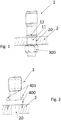
- FIG. 1 a conventional fastening for RF sockets is shown.
- the RF socket 1 After the RF socket 1 has been inserted into the passage opening 20 of the antenna cover 2, it is fastened from the rear of the antenna cover 2 by means of a nut 300, for example.
- the HF socket is pushed or plugged into the passage opening 20 of the antenna cover 2 up to a terminating web 12.
- a region of a fastening neck 11 of the HF socket 1 must protrude beyond the passage opening 20 of the antenna cover 2 to the underside of the antenna cover 2 and have a thread (not shown).
- the nut 300 is screwed onto the thread by means of a tool.
- the end web 12 serves as a type of washer or washer, so that the force acting by screwing on the nut 300 is made possible.
- the disadvantage of this fastening method is that the nut must be screwed on precisely so as not to cause tilting. Furthermore, the application of screw connections is time-consuming and therefore costly. It can also be difficult to use the tool to tighten if there is not enough space.
- FIG 2 Another typical type of fastening for HF sockets 1 on an antenna cover 2 is shown.
- the HF socket 1 is attached to a mounting plate 400 that is larger than the passage opening 20 of the antenna cover 2.
- the mounting plate 400 is attached to the top of the antenna cover 2, i.e. the side facing the HF socket 1, by means of several screws 401 attached to their outer ends.
- Disadvantage of this fastening method is that up to four screws have to be fastened here, which is an enormous expenditure of time.
- the mounting plate requires a great deal of space, which can be very disadvantageous in applications in which many sockets have to be mounted in a small space.
- the use of additional components such as screws also increases costs.
- a sleeve-shaped connection piece for receiving the inner and outer conductors of the housing coupler has at least one area which, at least in sections, forms a form-fitting connection with a housing wall of the electrical / electronic device.
- the connection piece of the housing coupler is preferably designed in one piece with the housing wall. The inner and outer conductor (s) can then be passed through the connector and fastened.
- US 2002/185327 A1 discloses an assembly according to the preamble of claim 1. It is therefore an object of this invention to provide an RF assembly by means of which the above-mentioned problems are overcome. Specifically, an HF plug connection is to be provided that can be easily assembled and dismantled and that creates an essentially play-free connection between the HF socket and the mounting wall.
- an HF assembly which comprises a combination of an HF plug-in element and a resilient securing element, by means of which the HF socket is fixed, preferably essentially free of play, on a mounting wall such as an antenna cover without screw connections becomes.
- the HF plug element of the HF plug connection according to the invention is first described in more detail below. Then the securing element of the HF connector according to the invention is described in detail. Individual exemplary embodiments will be explained in more detail later with reference to the drawing. The description always relates to a single RF plug connection and a passage opening, etc. However, this only serves to illustrate the principle of the invention. If several HF plug connections are to be arranged on a mounting wall, the invention can be transferred to every single HF plug connection and every single passage opening, etc.
- the HF plug-in element according to the invention of the HF assembly can in one embodiment be an HF socket.
- HF sockets normally consist of a mechanical assembly, i.e. mainly a mounting wall, and an electrical assembly that is surrounded by the mechanical assembly or is introduced into it and is protected by it.
- the HF plug-in element can also only be the electrical assembly that is normally located inside the mechanical assembly, that is to say, for example, the inner and outer conductors.
- the HF plug element is designed as described below.
- the HF plug-in element to be fastened to the assembly wall of an HF assembly such as an antenna has a fastening neck which can be inserted into the assembly wall via a through opening.
- the HF plug element has a connection area onto which the fuse element is plugged.
- the connection area is shaped in such a way that it is ensured that the securing element can be fixed between the connection area and the mounting wall on the HF plug-in element.
- the securing element and the HF plug connection thus form a connection free of play, or the securing element surrounds the HF plug element without play. In the second embodiment mentioned above, this connection is not necessarily free of play.
- a fixation of the components without play is to be understood as meaning that these components do not have any freedom of movement after assembly, ie the components can no longer move freely against each other or with one another, ie there is a form-fitting or force-fitting fixation. There is preferably no freedom of movement whatsoever between the components.
- connection area Another advantage of the proposed connection area is that it can be used as a heat trap for the soldering process in which a cable is attached to the HF plug-in element. This means that the HF plug-in element is less heated in the upper area during soldering.
- a part of the interior of the through opening of the mounting wall is machined through the fastening neck when the HF plug element is inserted into the corresponding through opening of the mounting wall.
- part of the material of the interior of the through opening of the mounting wall for example an antenna cover, is removed or scraped away or deformed or pressed by the insertion or insertion.
- the fastening neck of the HF plug-in element and also the mounting wall of the HF assembly or the passage opening have a material and a structure that make this possible. It is important here that the structure is designed in such a way that the HF plug-in element is fixed without play in the through opening after it has been inserted.
- the structure of the fastening neck of the HF plug-in element should, at least in partial areas, be different from the structure of the interior of the through opening.
- the interior of the through opening can be circular.
- the structure of the fastening neck of the HF plug-in element should not be completely circular, but rather have the shape of a polygon, e.g. a triangle, pentagon or hexagon.
- At least the fastening neck should have an area which, in interaction with the interior of the through opening, is fixed in a form-fitting or force-fitting manner that turning the HF plug element is difficult or impossible.
- the structure can have any complex geometry, these being limited by the manufacturing process and the costs for this.
- the mounting wall has a corresponding structure.
- the choice of whether the structure is provided in the interior of the through opening of the mounting wall, for example an antenna cover, or on the fastening neck of the HF plug-in element depends mainly on the manufacturing costs and the material of the mounting wall and the costs for providing the structure on the fastening neck .
- the mounting wall is preferably made of a non-conductive material but can also be made of a conductive material that has been treated to become non-conductive. For example, it can be anodized or coated with a plastic.
- a non-conductive insert can be introduced into the through opening between the interior of the through opening of the mounting wall and the fastening neck of the HF plug-in element.
- the insert must be fastened in such a way that it has a backlash-free connection on both sides when the HF plug element is pushed in or plugged in, ie does not slip and when forces are applied it does not result in the HF plug element being able to move or wobble.
- An insert part can be attached both to the fastening neck and to the interior of the through opening. In this application, it is important that the material can be machined, that is to say that it can be removed or scraped off or deformed or pressed by inserting the HF plug-in element. It is at the discretion of the user whether the HF plug element has the structure or whether the structure is located inside the through opening of the mounting wall and is removed or scraped off or deformed or pressed by inserting the HF plug element.
- the fastening neck or the inside of the mounting wall does not necessarily have a structure as mentioned above.
- the resilient securing element mainly fixes the components.
- an insertion aid can be attached to the through opening of the mounting wall, which makes it easier for the fitter to insert the HF plug-in element into the through opening.
- This insertion aid can be a notch or a projection which is adapted to the structure of the HF plug element in such a way that it only engages at one point during insertion and thus provides an orientation for inserting the fastening neck into the through opening.
- the HF plug-in element with the fastening neck is first inserted into the mounting wall, for example an antenna cover, that is to say from above or from the outside.
- the fastening neck of the HF plug element is pushed through the through opening of the mounting wall so that a connection area protrudes on the lower side of the mounting wall and forms a space with the mounting wall into which the securing element is inserted.
- the attachment of the fuse element can take place either from the side or by sliding over the connection area, so that a radial encompassing of the HF plug-in element is carried out by the securing element.
- each socket is provided with a securing element, since this is no longer visible from the outside.
- a recess for example in the form of a hole, is provided next to each HF plug-in element at a suitable location in the mounting wall, for example an antenna cover.
- the security element has a color that can be clearly seen through the recess, for example red, yellow or any other signal color. It can thus be ensured through a simple visual inspection that a fuse element is also attached to each HF plug-in element in an antenna array.
- the HF plug-in element is pushed or plugged into the mounting wall from below. Due to the geometry of the HF plug-in element, the through opening of the mounting wall must be larger than when fastening from above. It is advantageous here that the securing element is plugged onto the fastening neck of the HF plug-in element from above via the connection area or from the side and is thus visible after the final assembly. Another advantage of this type of fastening is that an axial load in the upward direction is absorbed by the terminating web of the HF plug-in element.
- antenna arrays in which the upper side of the mounting wall, i.e. the antenna cover, is directed downwards, tensile forces act downwards on the HF plug-in element. These tensile forces can be absorbed by the terminating web attached to the underside of the antenna cover, so that in this embodiment no further securing element has to be attached to the underside of the antenna cover.
- Another component of the RF assembly according to the invention is a resilient securing element which, due to its resilient properties, can be plugged or clamped into the connection area via the fastening neck of the HF plug element.
- the securing element is designed as a resilient element, so that the plugging or clamping onto the HF plug-in element can be carried out in such a way that a preload is created through which a backlash-free fastening or fixing between the HF plug-in element and the fuse element is created.
- the HF plug-in element cannot be moved by forces in the axial direction or by torsional forces and does not require a screw connection or other aids for fixing. It can also be preloaded Compensate for differences in tolerance in the thickness of the fastening neck of the HF plug-in element.
- the securing element due to its resilient properties, can be plugged or clamped onto the fastening neck of the HF plug-in element from the side. In another embodiment, the securing element can be pushed over the fastening neck of the HF plug-in element so that it clasps the fastening neck from above. In a further embodiment, the securing element is designed such that it has at least one spring arm.
- the shape of the securing element depends on the type of attachment to the HF plug-in element.
- a securing element that is pushed onto the fastening neck of the HF plug-in element from the side can have a horseshoe shape. With such a shape, it is sufficient that one arm of the horseshoe is designed as a spring arm. However, the second arm can also be designed as a spring arm. It must only be ensured that the securing element can be pushed over the HF plug-in element and has a pretensioning after it has been applied to the HF plug-in element, so that it can be fixed without play.
- a web can be provided in the case of such a shape on the side opposite the opening of the horseshoe.
- this web offers the possibility of inserting the securing element with greater force due to the larger contact surface on the fastening neck.
- the arms can become thinner towards the opening, since this reduces the force required to push them apart. In order to nevertheless ensure a good hold, the ends of the arms can again have a greater thickness than the arms themselves.
- a bevel is provided on the insides of the arms, that is to say in the areas pointing into the interior of the horseshoe shape, since this provides an insertion aid for fastening the securing element to the HF plug-in element. Due to the incline, the fastening does not have to be done edge to edge, but the securing element can be pushed or clamped more easily over the fastening neck.
- a bevel is provided in each of the designs of the securing element, for example even if the securing element is ring-shaped.
- the shape of the fuse element be adjusted. When choosing the design of the fuse element, care must be taken to ensure that the connection between the fuse element and the HF plug element is as free from play as possible.
- a horseshoe shape has been described as an example for this embodiment of the invention.
- the shape is not limited to a horseshoe shape. Rather, an essentially U-shape or other shapes are also possible which have an opening in their circumference, so that they can be attached to the HF plug-in element from the side.
- a securing element that is clamped from above via the connection area must have the same properties as a securing element that is clamped onto the fastening neck from the side.
- no opening in the circumference of the securing element is necessary here in order to push the securing element onto the HF plug-in element from above.
- An annular securing element can be used, the opening of the circular ring serving as an opening for attaching the securing element. If the securing element has such a ring shape, the entire shape must have resilient properties in order to ensure expansion when plugging on and contraction after plugging, so that a pretensioning and thus a backlash-free connection is created. Therefore, when choosing the material, care must be taken that greater spring forces act here when the shape of the securing element is pushed or pulled apart.
- the securing element can be connected to one or more securing elements to be attached to adjacent HF plug connections via a connecting web attached to it.
- the connecting web is preferably attached between two securing elements and is designed in such a way that it is longer than the connecting path between the HF plug connections.
- it is preferably designed as a resilient connecting web or has a joint in one area that is designed to cause a kink in the connecting web in the initial state so that the connecting web can be shortened and thus into the connecting web can be introduced.
- the connecting web By pressing the bend in the direction of the mounting wall, the connecting web is pressed down, the securing elements arranged at both ends of the connecting web are thus pressed onto the HF connector with a certain voltage and can thus enter into a backlash-free connection.
- the connecting web can also be in any other position, for example parallel to the mounting plate or at an angle to it be arranged, depending on the position in which the securing elements are attached to the connecting web.
- a further securing means can be attached to the joint as additional securing, for example.
- This securing means can be a pin with barbs on its underside, which is inserted over a through hole in the mounting plate and thus clicks into place on the rear side by means of the barbs.
- other securing means can also be used. It only has to be ensured that a firm connection with the mounting plate is created so that the connecting web cannot return to its starting position due to the voltage applied to it or the securing elements are clicked out of the HF plug-in connections.
- the connecting webs can be connected to one another, for example crosswise. This has the advantage that only one securing means has to be used for four securing elements.
- plastics can be used which are as inexpensive as possible to produce, that is to say can be produced, for example, by injection molding processes.
- examples are PPSU (polyphenylsulfone), PEI (polyetherimide) or PFA (perfluoroalkoxy polymers).
- PPSU polyphenylsulfone
- PEI polyetherimide
- PFA perfluoroalkoxy polymers
- the material must be suitable for absorbing forces in the axial direction and tilting moments without fatigue or breaking.
- the securing element can be designed in such a way that it can also absorb torques.
- the fuse element should have a good temperature resistance, the requirements here can vary depending on the application. For example, heat generated by losses can act on the fuse element and the HF plug-in element. Although the fuse element is non-conductive, it is also heated by the power loss that occurs and the heating of the HF plug element. For this reason, too, the material has to withstand temperatures of approx. -50 to + 130 ° C or more without melting or breaking. Any material that has these properties can be used for the fuse element. This material is preferably non-conductive. In the event that the material is conductive, it must be sheathed or treated in order to avoid intermodulation caused by the fuse element.
- the securing element can have assembly aids in one or more areas. These assembly aids can be used to pull the pretensioned securing element apart by means of a tool in order to push or click it over the fastening neck of the HF plug-in element. At the same time, such an assembly aid can serve to attach a locking element to the securing element in order to additionally secure it.
- a further locking element as described above can be attached to at least one area of the securing element in order to achieve additional protection.
- the locking element can be attached to the securing element and thus prevent the securing element from snapping out.
- Such a locking of the securing element can take place, for example, by a clamp with or without a wedge protruding into the opening of the securing element as a locking element, which is attached in or on the assembly aids in order to prevent the securing element from snapping out.
- a latching element can be arranged on the securing element, which latches with a counterpart arranged on the mounting wall after the securing element has been attached and thus prevents the securing element from rotating.
- the counterpart can also be part of the mounting wall.
- a locking element can be a clip which is inserted into holes serving as a mounting element.
- one or more latching elements can be attached to the securing element, which, in cooperation with a corresponding counterpart arranged on the mounting wall, for example an antenna cover, can prevent the securing element from snapping out after it has been plugged on, the counterpart also Can be part of the mounting wall.
- FIGS 3 and 4 show sectional views of different basic embodiments of RF plug connections according to the invention.
- an HF socket 1 serving as an HF plug element is shown, the fastening neck 11 of which is inserted into a passage opening 20 of a mounting wall, which is designed here as an antenna cover 2, up to the stop of the terminating web 12.
- the HF sockets 1 of both embodiments have a connection area 13, which is a
- the securing element 3 can be clicked into place so that it cannot slip in the axial direction.
- the securing element 3 is shown with beveled edges 33, since the best surface pressure takes place here and thus the smallest freedom from play is achieved.
- the shape of the securing element 3 can be adapted to the shape of the connecting area 13. It is important that the securing element 3 can be attached to the connection area 13 of the HF socket 1 in such a way that a movement of the HF socket in the axial direction, i.e. out of the antenna cover, and also a torsion, i.e. rotation of the socket in the antenna cover 2 are not possible, i.e. a backlash-free connection between HF socket 1 and antenna cover 2 is achieved.
- HF sockets 1 shown differ in that the in Figure 3
- the HF socket 1 shown is plugged into the antenna cover 2 from above.
- the HF socket 1 shown is plugged into the antenna cover 2 from below, which has the effect that, in the event of axial forces in the direction of the top of the cover, the terminating web 12 prevents the HF socket 1 from slipping out.
- This advantage can be used above all if, after final assembly, the top of the antenna cover 2 is directed downwards, so that the weight of an attached cable alone exerts an axial force downwards on the HF socket.
- the two embodiments also differ in that the in Figure 3 According to the invention shown fuse element 3 is arranged on the side of the antenna cover 2, which is no longer visible from the outside after final assembly.
- the inventive fuse element 3 of the in Figure 4 The embodiment shown, however, is visible after final assembly on the outside or top of the antenna cover 2.
- the securing element 3 cannot be pushed over the fastening neck 11 from the side, but from above (not shown in the figures).
- it is preferably ring-shaped with an opening on its upper side in order to keep the socket free or to be able to be plugged over it.
- it is designed in such a way that it has a shape on its underside, with which it is clamped to the connecting area 13 of the HF plug element 1, which secures the HF plug element 1 against movements in the axial direction and against rotational movements, i.e. a backlash-free connection is achieved.
- the material of the securing element 3 must above all have elastic properties, since it must be stretched considerably in order to be able to be pushed over the plug-in element. However, it must also have the property of returning to its original shape in order to achieve the desired holding properties.
- This embodiment of the securing element 3 is preferably selected when the in Figure 4 The variant of the HF connector shown is used, so the fuse element 3 is visible after the final assembly. In addition to the required elasticity, when choosing the material for the securing element, it is important that it has a certain weather resistance, since in this embodiment it is attached outside and is therefore exposed to a wide variety of environmental conditions such as ice, hail, UV light or water. If the in Figure 3 If the variant shown is selected, the securing element 3 must be attached to the fastening neck 11 before further connections are attached to the underside of the HF plug-in element 1, for example cables.
- Figures 5a to 5c show an alternative embodiment of the RF connector according to the invention.
- the HF plug element 1 is not an HF socket, but only the electrical assembly that is normally located inside the mechanical assembly of the HF socket, see Figure 5b .
- the mechanical assembly is formed in such a way that it is already fixed in the mounting wall 2 of the RF assembly, for example the antenna, that is, is formed in one piece and can be encapsulated with a non-conductive material such as plastic.
- the electrical assembly for example at least the inner and outer conductor of the antenna, is integrated into the in Figure 5a Mounting wall combination shown introduced and secured with the securing element 3 according to the invention, as in Figure 5c shown.
- the arrangement of the HF plug element can as in Figures 3 and 4 shown from above or below. This depends on how the mounting wall combination was made.
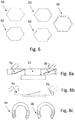
- Figure 6 shows exemplary sectional views of a structure 50 of the fastening neck 11 or the interior of the passage opening 20 of the mounting wall of the RF assembly 2 according to different embodiments of the present invention.
- both the fastening neck 11 and the inside of the passage opening 20 of the mounting wall of the HF assembly 2 can have a structure 50 in order to enable the HF plug-in element 1 to be fastened to the assembly wall of the HF assembly 2 without play.
- the structure can be designed as a hexagon which, when inserted into the passage opening 20, processes the inside of the passage opening 20 so that material is removed or scraped off or deformed or pressed.
- the structure 50 When the structure 50 is attached to the fastening neck 11, the structure 50 scrapes off part of the inside of the passage opening 20 of the mounting wall of the RF assembly 2. If the passage opening 20 has the structure 50, part of it is removed or scraped off or deformed or pressed by inserting the fastening neck 11, since this has a shape which ensures that it removes part of the structure 50 of the passage opening when it is inserted or scrapes. This means that the fastening neck is at least slightly larger Diameter than the passage opening 30 must have. Both types of attachment of the structure 50 ensure that a backlash-free connection is created between the HF plug-in element 1 and the mounting wall of the HF assembly 2. Further examples of structures 50 according to the invention are also shown in FIG Figure 6 shown which meet the requirements specified above.
- FIG. 6 shows only examples of structures. Any further conceivable structure could be used in place of the one shown. These structures 50 can be used alone or in combination. Structures 50 are shown here, for example, which have a zigzag line, a trapezoid, a semicircle, a rectangle or a square. Any shapes, including complex shapes, can be used, provided that depressions or elevations are preferably arranged in the fastening neck 11 or the inside of the passage opening 20, which create a play-free connection between the HF plug-in element by removing or scraping or deforming or pressing 1 and the mounting wall of the HF assembly 2. Alternatively, the mounting wall of the HF assembly can also have an inclined contour which generates an axial pretensioning of the HF plug-in element via the securing element.
- All of the structures 50 shown can be arranged on the fastening neck 11 or on the inside of the passage opening 20.
- the decision as to where to place the structure 50 will depend on factors such as manufacturing cost, ease of manufacture, or material, and will be made by those skilled in the art according to the desired application.
- Figure 7a shows a plan view of a fuse element of an RF connector according to an embodiment of the present invention.
- the securing element 3 is designed in the form of a horseshoe and has a web 30 on the side opposite the opening. This web serves to distribute the forces ⁇ max , which act on the area to which the web 30 is attached when the two spring arms 31 are pulled or bent apart, over a larger area.
- the securing element 3 in Figure 7a a widening 32 of the arms 31 at the respective ends pointing towards the opening. This has the advantage that as a result the area for clicking or clamping is larger and, as a result, a greater holding force can be exerted on the fastening neck 11 of the HF socket.
- one arm or both arms can serve as spring arms.
- the securing element 3 also has assembly aids 60 which are attached to the widening 32 of the arms 31.
- the assembly aids 60 here are holes through the opening of which a suitable tool can be inserted in order to make it easier to pull the arms 31 apart. Additionally, these holes can be used as a bracket for a Serve locking element. Examples of locking elements are in Figures 11a and 11b shown.
- the shape of the locking element is adapted to the shape of the widening 32 of the arms 31 or the type of opening. In the case of the securing element shown, one arm or both arms can serve as spring arms.
- FIG. 11 shows a perspective view of a fuse element 3 of an HF plug connection according to FIG Fig 7a .
- the securing element 3 is designed in the form of a horseshoe with a web 30 on the side opposite the opening.
- the securing element 3 has beveled edges 33 on the regions of the arms 31 pointing into the interior of the horseshoe shape, which enable the securing element 3 to be clicked into place in a simplified manner.
- one arm or both arms can serve as spring arms.
- Figure 7c shows a perspective view of an alternative embodiment of a fuse element 3 of an RF plug connection according to the present invention.
- the securing element 3 is designed in the form of a horseshoe with a web 30 on the side opposite the opening.
- the securing element 3 also has beveled edges 33 on the regions of the arms 31 pointing into the interior of the horseshoe shape, which enable the securing element 3 to be clicked into place in a simplified manner.
- one arm or both arms can serve as spring arms.
- the securing element 3 of this embodiment also has holes as assembly aids 60, but does not have any widening of the arms 31 like the embodiments in FIG Figures 7a and 7b .
- Figures 8a to 8c are views of a mounted on the HF plug element 1 securing element 3, which consists of two parts 3a and 3b and has stepped or sawtooth-shaped inclined edges, shown for illustration.
- the beveled, stepped or sawtooth-shaped edges make it easier to attach parts 3a and 3b of the securing element, since they are not attached edge to edge, which would cause greater friction.
- the two parts 3a and 3b of the securing element are pushed onto the connecting neck 13 from two sides and, when pushed on, interlock with one another in such a way that a ring is created around the connecting neck 13.
- Beveled edges can also be used in the case of securing elements without an opening, which for example are plugged onto the HF plug element 1 from above (not shown). In the case of the securing element shown, one arm or both arms can serve as spring arms.
- Figures 9a to 9d show views of a plurality of securing elements 3 connected to a connecting web 14.
- Figures 9a and 9b show a top view of two or four securing elements connected to one another via connecting webs 14.
- Figure 9c it is shown how the connecting web 14 forms a kink in order to be able to be introduced into the connecting path between two HF plug-in elements 1.
- Figure 9d shows a principle of an additional fuse 15, designed here as a pin with barbs. The pin is inserted into a through hole in the mounting plate and clicks with its barbs on the back of the mounting plate 2.
- the additional fuse 15 ensures that a firm connection with the mounting plate is created so that the connecting web cannot return to its starting position due to the voltage applied to it or the fuse elements are clicked out of the HF plug-in connections.
- FIGs 10a and 10b show a view of an insertion aid 21 for an RF connector according to an embodiment of the present invention.
- the insertion aid 21 is a defined structure which, according to the key and lock principle, is arranged on the fastening neck 11 and in an area close to, directly on or in the passage opening 20 of the mounting wall of the RF assembly 2.
- the insertion aid 21 serves to facilitate the insertion of the HF plug element 1 into the mounting wall of the HF assembly 2 or to specify an alignment for the assembly of the HF plug element 1.
- the insertion aid 21 is formed directly in the passage opening 20 as a recess which corresponds to the diameter of the fastening neck 11.
- the HF plug-in element shown here as HF socket 1
- HF socket 1 can thus be prepositioned in the opening in such a way that, for example, in a subsequent assembly step, the HF socket 1 only has to be pressed or hammered into the passage opening 20.
- Such an insertion aid 21 can be necessary, for example, if the components are to be prepositioned for assembly. It can also be the case that a predetermined assembly sequence must be adhered to, so that the HF plug-in element or the HF socket 1 can only be assembled in a certain predetermined assembly step due to the insertion aid 21.
- An insertion aid 21 can also be provided for reasons of space, namely if, for example, the space around the HF plug element is insufficient to use a positioning tool. Thanks to the insertion aid 21, the HF plug-in element can nevertheless be mounted in the correct position.
- FIGs 11a and 11b views of locking elements 70 that can be attached to the securing element 3 are shown by way of example.
- Figure 11a shows a bracket or bar inserted at the ends of the arms 31 in the assembly aids 60, which are each a hole here.
- This clip can also be provided with a filler web (not shown) which fills the opening of the securing element 3 and thus provides additional stability.
- Figure 11b a clip is attached to the arms 31 from the side of the opening of the securing element, which clip clicks into the widening of the arms 31 and thus provides an additional safeguard against the securing element being clicked out.
- a ring can be arranged around the securing element 3, which keeps it in shape or even exerts a force on it that presses the securing element 3 further together.
- FIGs 12a and 12b a view of a latching element 80 and a corresponding counterpart 81 according to an embodiment of the present invention is shown.
- Figure 12a shows a latching element 80 arranged on the securing element 3 according to an embodiment of the present invention.
- the latching element 80 is arranged, for example, at the ends of the arms 31 towards the opening of the securing element 3.
- Figure 12b shows a corresponding counterpart 81 to the one in FIG Figure 12a latching element 80 shown, which serves to ensure that the securing element 3, after being attached, latches with the counterpart 81 in such a way that it can no longer rotate.
- FIGs 12a and 12b such a latching element 80 and the counterpart 81 are shown by way of example. However, any shapes can be used which are suitable for fulfilling the stated object.
- Figures 13a and 13b show two alternatives of a non-conductive insert 90 arranged in the through opening 20 of the mounting wall of the RF assembly 2 and described in the introduction.
- the insert 90 can either be fastened in the through opening 20, or it can be arranged on the fastening neck 11 and with this in the Passage opening can be pushed. In both cases, the insert 90 must have a structure 50 which is removed or scraped off or deformed or pressed when it is inserted into the through opening 20. This is due to the fact that when it is necessary to use an insert 90, both the mounting wall of the RF assembly 2 and the RF plug element 1 are made of a conductive material that can be removed or scraped off or deformed or pressed Structure would be very difficult to achieve.
- the insert is shaped in such a way that it avoids conductive connections between the mounting wall and the HF plug-in element, as in FIGS Figures 13a and 13b alternatives shown.
Landscapes
- Engineering & Computer Science (AREA)
- General Engineering & Computer Science (AREA)
- Mechanical Engineering (AREA)
- Details Of Connecting Devices For Male And Female Coupling (AREA)
- Insertion Pins And Rivets (AREA)
Description
- Die Erfindung betrifft eine HF-Baugruppe gemäß Patentanspruch 1. In der Antennentechnik werden zahlreiche HF-Steckverbindungen, also Steckverbindungen für Hochfrequenz-(HF)-Anwendungen, in unterschiedlicher Ausgestaltung verwendet. Solche HF-Steckverbindungen dienen dazu, eine HF-Buchse oder mehrere HF-Buchsen in Durchlassöffnungen von wandförmigen HF-Baugruppen, auch als Montagewände für HF-Baugruppen bezeichnet und beispielsweise als Antennendeckel ausgeführt, zu stecken, hinter dem die Antenne mit allen zugehörigen Komponenten angeordnet ist. Eine solche Anordnung ist vor allem bei Mobilfunkantennenarrays geläufig. Ein Hauptproblem bei der Montage ist es, die HF-Buchse so auf den Deckel zu montieren, dass diese fest sitzt. Dies ist wichtig, um ein Ausleiern der Verbindung und damit ein Ausreißen der Buchse zu verhindern, da auf diese größere Kräfte wirken können.
- In
Figur 1 ist eine herkömmliche Befestigung für HF-Buchsen gezeigt. Hier wird nach dem Einstecken der HF-Buchse 1 in die Durchlassöffnung 20 des Antennendeckels 2 diese mittels beispielsweise einer Mutter 300 von der Rückseite des Antennendeckels 2 her befestigt. Die HF-Buchse wird bis zu einem Abschluss-Steg 12 in die Durchlassöffnung 20 des Antennendeckels 2 geschoben bzw. gesteckt. Um eine Mutter 300 anzubringen, muss ein Bereich eines Befestigungshalses 11 der HF-Buchse 1 über die Durchlassöffnung 20 des Antennendeckels 2 zur Unterseite des Antennendeckels 2 hinaus ragen und ein Gewinde (nicht gezeigt) aufweisen. Die Mutter 300 wird mittels eines Werkzeugs auf das Gewinde geschraubt. Beim Festschrauben dient der Abschluss-Steg 12 als eine Art Beilag- oder Unterlegscheibe, so dass eine Verteilung der durch das Anschrauben der Mutter 300 wirkenden Kraft ermöglicht wird. Nachteilig bei dieser Befestigungsmethode ist, dass ein genaues Aufschrauben der Mutter erfolgen muss, um kein Verkanten zu verursachen. Ferner ist das Anbringen von Schraubverbindungen zeitraubend und damit kostenintensiv. Auch kann es bei Platzmangel schwierig sein, das Werkzeug zum Festziehen zu verwenden. - In
Figur 2 ist eine weitere typische Befestigungsart für HF-Buchsen 1 an einem Antennendeckel 2 gezeigt. Hier ist die HF-Buchse 1 auf einer Montageplatte 400 angebracht, die größer ist als die Durchlassöffnung 20 des Antennendeckels 2. Die Montageplatte 400 wird auf der Oberseite des Antennendeckels 2, also der der HF-Buchse 1 zugewandten Seite, mittels mehreren Schrauben 401 an ihren äußeren Enden befestigt. Nachteilig bei dieser Befestigungsmethode ist, dass hier bis zu vier Schrauben befestigt werden müssen, was einen enormen Zeitaufwand darstellt. Zusätzlich wird durch die Montageplatte sehr viel Platz benötigt, was bei Anwendungen, bei denen viele Buchsen auf kleinem Raum montiert werden müssen, sehr nachteilig sein kann. Durch die Verwendung zusätzlicher Bauteile wie etwa Schrauben erhöhen sich ferner die Kosten. - Eine Alternative Befestigungsmethode ist in der
DE102010014154 B4 beschrieben. Hier weist ein hülsenförmiges Anschlussstück zur Aufnahme des Innen- und Außenleiters des Gehäusekupplers wenigstens einen Bereich auf, der mit einer Gehäusewand des elektrisch/elektronischen Gerätes wenigstens abschnittsweise eine Formschlussverbindung eingeht. Das Anschlussstück des Gehäusekupplers ist hierbei mit der Gehäusewand bevorzugt einstückig ausgebildet. Der bzw. die Innen- und Außenleiter können dann durch das Anschlussstück geführt und befestigt werden. - Eine weitere gängige Befestigungsmethode ist die sogenannte Push-Pull-Verriegelung, die beispielsweise in der nicht mehr anhängigen Patentschrift
DE 000004439852 C2 beschrieben ist. Diese Befestigungsmethode bezieht sich allerdings auf die Verbindung zwischen Buchse und Stecker und nicht auf die Verbindung zwischen Buchse und Deckel. Vorteilhaft bei dieser Verbindungsart ist, dass sie nicht mittels eines Werkzeugs verschraubt werden muss. Allerdings ist sie einerseits teuer und stellt auch nicht sicher, dass die HF-Buchse so befestigt ist, dass sie sich nicht bewegen kann, da diese Art der Verriegelung nicht sehr stabil gegen Torsionsbelastungen ist. Auch aus diesem Grund ist eine erfindungsgemäße Verwendung als Verbindung zwischen Buchse und Deckel nicht vorteilhaft. -
US 2002/185327 A1 offenbart eine Baugruppe gemäss dem Oberbegriff des Anspruchs 1. Deshalb ist es eine Aufgabe dieser Erfindung, eine HF-Baugruppe bereitzustellen, durch welche die oben genannten Probleme überwunden werden. Speziell soll eine HF-Steckverbindung bereitgestellt werden, die einfach montiert und demontiert werden kann, und die dabei eine im Wesentlichen spielfreie Verbindung zwischen HF-Buchse und Montagewand herstellt. - Diese Aufgabe wird erfindungsgemäß durch die Merkmale des Patentanspruchs 1 gelöst. Vorteilhafte Ausgestaltungen sind Gegenstand der abhängigen Ansprüche.
- Vorgeschlagen wird erfindungsgemäß eine HF-Baugruppe, die eine Kombination aus einem HF-Steckelement und einem federnden Sicherungselement umfasst, durch das eine Fixierung, bevorzugt eine im Wesentlichen spielfreie, Befestigung der HF-Buchse an einer Montagewand wie einem Antennendeckel ohne Schraubverbindungen erreicht wird.
- Nachfolgend wird zuerst das HF-Steckelement der erfindungsgemäßen HF-Steckverbindung genauer beschrieben. Danach wird das Sicherungselement der erfindungsgemäßen HF-Steckverbindung im Detail beschrieben. Einzelne Ausführungsbeispiele werden später unter Bezugnahme auf die Zeichnung näher erläutert. Die Beschreibung bezieht sich immer auf eine einzelne HF-Steckverbindung und eine Durchlassöffnung etc. Allerdings dient dies nur zur Veranschaulichung des Prinzips der Erfindung. Wenn mehrere HF-Steckverbindungen auf einer Montagewand angeordnet werden sollen, kann die Erfindung auf jede einzelne HF-Steckverbindung und jede einzelne Durchlassöffnung etc. übertragen werden.
- Das erfindungsgemäße HF-Steckelement der HF-Baugruppe kann in einem Ausführungsbeispiel eine HF-Buchse sein. HF-Buchsen bestehen normalerweise aus einer mechanischen Baugruppe, also hauptsächlich einer Montagewand, und einer elektrischen Baugruppe, die von der mechanischen Baugruppe umgeben ist bzw. in diese eingeführt ist und von dieser geschützt wird. In einem alternativen Ausführungsbeispiel kann das HF-Steckelement auch lediglich die elektrische Baugruppe sein, die sich normalerweise im Inneren der mechanischen Baugruppe befindet, also beispielsweise Innen- und Außenleiter. Das HF-Steckelement ist wie nachfolgend beschrieben ausgebildet.
- Das an der Montagewand einer HF-Baugruppe wie einer Antenne zu befestigende HF-Steckelement weist erfindungsgemäß einen Befestigungshals auf, der über eine Durchgangsöffnung der Montagewand in diesen eingesteckt werden kann. Zusätzlich weist das HF-Steckelement einen Verbindungsbereich auf, an den das Sicherungselement aufgesteckt wird. Der Verbindungsbereich ist derart geformt, dass gewährleistet wird, dass das Sicherungselement zwischen dem Verbindungsbereich und der Montagewand an dem HF-Steckelement fixiert werden kann. In der ersten oben genannten Ausführungsform gehen das Sicherungselement und die HF-Steckverbindung somit eine spielfreie Verbindung ein bzw. das Sicherungselement umgibt das HF-Steckelement spielfrei. In der zweiten oben genannten Ausführungsform ist diese Verbindung nicht zwingend spielfrei.
- Unter spielfrei ist eine Fixierung der Komponenten zu verstehen, die diesen Komponenten nach der Montage keinen Bewegungsfreiraum lässt, d.h. die Komponenten können sich nicht mehr gegeneinander oder miteinander frei bewegen, d.h. es besteht eine form- bzw. kraftschlüssige Fixierung. Bevorzugt ist keinerlei Bewegungsfreiraum zwischen den Komponenten vorhanden.
- Es kann aber auch eine geringe Toleranz bzw. ein geringes Spiel zwischen den Komponenten zugelassen werden. Dieses Spiel muss so gering sein, dass mechanische oder sonstige Belastungen keinen Einfluss auf die Fixierung und damit die Funktionstüchtigkeit der Komponenten haben, d.h. es darf durch das Spiel nur eine minimale Bewegung erfolgen können.
- Ein weiterer Vorteil des vorgeschlagenen Verbindungsbereichs ist, dass dieser für den Lötvorgang, bei dem ein Kabel an dem HF-Steckelementbefestigt wird, als Wärmefalle genutzt werden kann. Somit wird beim Löten das HF-Steckelement im oberen Bereich weniger erwärmt.
- Ferner wird in der ersten oben genannten Ausführungsform durch den Befestigungshals beim Einstecken des HF-Steckelements in die entsprechende Durchgangsöffnung der Montagewand ein Teil des Inneren der Durchgangsöffnung der Montagewand, beispielsweise eines Antennendeckels, spanend bearbeitet. Das heißt, dass ein Teil des Materials des Inneren der Durchgangsöffnung der Montagewand, beispielsweise eines Antennendeckels, durch das Einschieben bzw. Einstecken abgetragen bzw. weggeschabt oder verformt bzw. verpresst wird. Dies kann dadurch geschehen, dass der Befestigungshals des HF-Steckelements und auch die Montagewand der HF-Baugruppe bzw. die Durchlassöffnung ein Material und eine Struktur aufweist, die dies ermöglicht. Wichtig ist hierbei, dass die Struktur derart ausgebildet ist, dass das HF-Steckelement in der Durchgangsöffnung nach dem Einstecken spielfrei fixiert ist. Das heißt für die Struktur, dass die Struktur des Befestigungshalses des HF-Steckelements zumindest in Teilbereichen eine andere sein sollte als die Struktur des Inneren der Durchgangsöffnung. Beispielsweise kann das Innere der Durchgangsöffnung kreisförmig sein. Dann sollte die Struktur des Befestigungshalses des HF-Steckelements nicht vollständig kreisförmig sein, sondern beispielsweise die Form eines Mehrkants, z.B. eines Drei-, Fünf- oder Sechskants, haben. Zumindest sollte der Befestigungshals einen Bereich aufweisen, der in Zusammenspiel mit dem Inneren der Durchgangsöffnung derart form- bzw. kraftschlüssig fixiert ist, dass ein Drehen des HF-Steckelements nur schwer oder gar nicht möglich ist. Die Struktur kann hierfür eine beliebig komplizierte Geometrie aufweisen, wobei diese durch das Herstellungsverfahren und die Kosten dafür begrenzt sind.
- In einem zu dem vorangehenden Ausführungsbeispiel alternativen Ausführungsbeispiel weist die Montagewand eine entsprechende Struktur auf. Die Wahl, ob die Struktur in dem Inneren der Durchgangsöffnung der Montagewand, z.B. eines Antennendeckels, bereitgestellt wird oder am Befestigungshals des HF-Steckelements, hängt hauptsächlich von den Herstellungskosten und dem Material der Montagewand und den Kosten für die Bereitstellung der Struktur auf dem Befestigungshals ab. Die Montagewand wird bevorzugt aus einem nicht-leitenden Material hergestellt, kann aber auch aus einem leitenden Material bestehen, das behandelt wurde, um nicht-leitend zu werden. Es kann beispielsweise eloxiert werden oder mit einem Kunststoff ummantelt. Alternativ kann in die Durchgangsöffnung ein nicht-leitendes Einlegeteil zwischen dem Inneren der Durchgangsöffnung der Montagewand und dem Befestigungshals des HF-Steckelements eingebracht werden. Das Einlegeteil muss derart befestigt sein, dass es bei Einschieben bzw. Einstecken des HF-Steckelements eine spielfreie Verbindung zu beiden Seiten hat, d.h. nicht verrutscht und bei Einwirkung von Kräften nicht dazu führt, dass sich das HF-Steckelement bewegen bzw. wackeln kann. Ein Einlegeteil kann sowohl am Befestigungshals als auch am Inneren der Durchgangsöffnung angebracht sein. Wichtig ist bei dieser Anwendung, dass das Material spanend bearbeitet werden kann, also durch Einstecken des HF-Steckelements abgetragen bzw. abgeschabt oder verformt bzw. verpresst werden kann. Hierbei liegt es im Ermessen des Anwenders, ob das HF-Steckelement die Struktur aufweist oder ob sich die Struktur im Inneren der Durchgangsöffnung der Montagewand befindet und durch Einstecken des HF-Steckelements abgetragen bzw. abgeschabt oder verformt bzw. verpresst wird.
- In der zweiten oben genannten Ausführungsform weisen der Befestigungshals oder die Innenseite der Montagewand nicht unbedingt eine Struktur wie oben erwähnt auf. Hier sorgt das federnde Sicherungselement hauptsächlich für die Fixierung der Komponenten.
- In einer weiteren Ausführung kann an der Durchgangsöffnung der Montagewand eine Einführhilfe angebracht sein, die es dem Monteur erleichtert, das HF-Steckelement in die Durchgangsöffnung einzuführen. Diese Einführhilfe kann eine Einkerbung oder ein Vorsprung sein, welche der Struktur des HF-Steckelements derart angepasst sind, dass sie nur an einer Stelle beim Einführen greifen und somit eine Ausrichtung zum Einführen des Befestigungshalses in die Durchgangsöffnung vorgeben.
- In einer Ausführungsform wird das HF-Steckelement mit dem Befestigungshals zuerst in die Montagewand, z.B. einen Antennendeckel, gesteckt, d.h. von oben bzw. von außen. Als oben, Oberseite oder Außenseite wird hier die Seite, die nach der Endmontage der HF-Baugruppe, beispielsweise einer Antenne, von außen zu sehen ist, bezeichnet. Als unten, Unterseite oder Innenseite wird die Seite bezeichnet, die nach der Endmontage der HF-Baugruppe, beispielsweise einer Antenne, von außen nicht mehr zu sehen ist. Bei der Befestigung des HF-Steckelements von oben wird der Befestigungshals des HF-Steckelements durch die Durchgangsöffnung der Montagewand geschoben, so dass ein Verbindungsbereich auf der unteren Seite der Montagewand herausragt und mit der Montagewand einen Raum bildet, in den das Sicherungselement gesteckt wird. Das Aufstecken des Sicherungselements kann entweder von der Seite oder durch Schieben über den Verbindungsbereich erfolgen, so dass eine radiale Umgreifung des HF-Steckelements durch das Sicherungselement erfolgt.
- Bei dieser Art der Befestigung ist eines schwierig, nach der Endmontage sicherzustellen, dass jede Buchse mit einem Sicherungselement versehen ist, da dieses nicht mehr außen sichtbar ist. Um eine entsprechende Qualitätssicherung zu gewährleisten, ist in einer Ausführung der Erfindung eine Ausnehmung, beispielsweise in Form eines Loches, neben jedem HF-Steckelement an geeigneter Stelle in der Montagewand, beispielsweise einem Antennendeckel, vorgesehen. Ferner ist es dann vorteilhaft, wenn das Sicherungselement eine Farbe aufweist, die deutlich durch die Ausnehmung zu sehen ist, beispielsweise rot, gelb oder jede andere Signalfarbe. Somit kann durch einfache Sichtkontrolle sichergestellt werden, dass an jedem HF-Steckelements in einem Antennenarray auch ein Sicherungselement angebracht ist.
- In einer weiteren Ausführungsform wird das HF-Steckelement von unten in die Montagewand geschoben bzw. gesteckt. Hierbei muss aufgrund der Geometrie des HF-Steckelements die Durchgangsöffnung der Montagewand größer sein als bei der Befestigung von oben. Vorteilhaft ist hier, dass das Sicherungselement von oben über den Verbindungsbereich auf den Befestigungshals des HF-Steckelements oder von der Seite gesteckt wird und somit nach der Endmontage sichtbar ist. Ein weiterer Vorteil dieser Befestigungsart ist es, dass eine axiale Belastung in Richtung nach oben durch den Abschluss-Steg des HF-Steckelements abgefangen wird. Durch die Montage von Antennenarrays, bei denen die obere Seite der Montagewand, also des Antennendeckels nach unten gerichtet ist, wirken Zugkräfte nach unten auf das HF-Steckelement. Diese Zugkräfte können durch den an der Unterseite des Antennendeckels angebrachten Abschluss-Steg abgefangen werden, so dass in dieser Ausführung kein weiteres Sicherungselement an der Unterseite des Antennendeckels angebracht werden muss.
- Ein weiterer Bestandteil der erfindungsgemäßen HF-Baugruppe ist ein federndes Sicherungselement, das aufgrund seiner federnden Eigenschaften über den Befestigungshals des HF-Steckelements in den Verbindungsbereich gesteckt bzw. geklemmt werden kann. Das Sicherungselement ist als federndes Element ausgebildet, so dass das Stecken bzw. Klemmen auf das HF-Steckelement derart erfolgen kann, dass eine Vorspannung entsteht, durch die eine spielfreie Befestigung bzw. Fixierung zwischen HF-Steckelement und Sicherungselement entsteht. Durch diese spielfreie Befestigung kann das HF-Steckelement nicht durch Kräfte in axialer Richtung oder durch Torsionskräfte bewegt werden und benötigt zur Fixierung keine Verschraubung oder andere Hilfsmittel. Ferner kann es durch seine Vorspannung Toleranzunterschiede bei der Dicke des Befestigungshalses des HF-Steckelements ausgleichen.
- In einer Ausgestaltung der Erfindung kann das Sicherungselement aufgrund seiner federnden Eigenschaften an den Befestigungshals des HF-Steckelements von der Seite her aufgesteckt bzw. geklemmt werden. In einer anderen Ausführungsform kann das Sicherungselement über den Befestigungshals des HF-Steckelements geschoben werden, so dass es den Befestigungshals von oben umklammert. In einer weiteren Ausführungsform ist das Sicherungselement derart ausgeführt, dass es zumindest einen Federarm aufweist.
- Die Form des Sicherungselements hängt von der Art der Befestigung an dem HF-Steckelement ab. Beispielsweise kann ein Sicherungselement, das von der Seite auf den Befestigungshals des HF-Steckelements aufgesteckt wird, eine Hufeisenform aufweisen. Bei einer solchen Form reicht es aus, dass ein Arm des Hufeisens als Federarm ausgebildet ist. Allerdings kann auch der zweite Arm als Federarm ausgebildet sein. Es muss lediglich sichergestellt sein, dass das Sicherungselement über das HF-Steckelement geschoben werden kann und eine Vorspannung nach dem Aufbringen auf das HF-Steckelement aufweist, so dass eine spielfreie Fixierung erfolgen kann. Um die an bestimmten Stellen auftretenden Spannungen zu minimieren kann bei einer solchen Form an der der Öffnung des Hufeisens gegenüber liegenden Seite ein Steg vorgesehen sein. Durch diesen Steg werden die bei einem Auseinanderziehen der Arme des hufeisenförmigen Sicherungselements wirkenden punktuellen Kräfte auf eine größere Fläche verteilt und somit eine Bruchgefahr verringert. Außerdem bietet ein solcher Steg die Möglichkeit, das Sicherungselement mit größerer Kraft aufgrund der größeren Angriffsfläche auf den Befestigungshals zu stecken. Zusätzlich oder alternativ können die Arme zur Öffnung hin dünner werden, da hierdurch die zum Auseinanderdrücken nötige Kraft kleiner wird. Um dennoch einen guten Halt zu gewährleisten, können die Enden der Arme wiederum eine größere Dicke als die Arme selbst aufweisen.
- Erfindungsmässig ist es, an den Innenseiten der Arme, also an den ins Innere der Hufeisenform zeigenden Bereichen, eine Schräge vorgesehen, da hierdurch eine Einführhilfe zur Befestigung des Sicherungselements an dem HF-Steckelement erreicht wird. Durch die Schräge muss die Befestigung nicht Kante auf Kante erfolgen, sondern das Sicherungselement kann leichter über den Befestigungshals geschoben bzw. geklemmt werden.
- Eine Schräge ist bei jeder der Ausführungen des Sicherungselements vorgesehen, z.B. auch wenn das Sicherungselement ringförmig ist. Je nach Ausführung des Verbindungsbereichs des HF-Steckelements kann die Form des Sicherungselements angepasst werden. Dabei ist bei der Wahl der Ausgestaltung des Sicherungselements darauf zu achten, dass eine möglichst spielfreie Verbindung zwischen Sicherungselement und HF-Steckelement entsteht.
- Für diese Ausgestaltung der Erfindung wurde als Beispiel eine Hufeisenform beschrieben. Die Form ist aber nicht auf eine Hufeisenform beschränkt. Vielmehr ist auch eine im Wesentlichen U-Form oder andere Formen möglich, die eine Öffnung in ihrem Umfang aufweisen, so dass sie auf das HF-Steckelement von der Seite befestigt werden können.
- Des Weiteren muss ein Sicherungselement, das über den Verbindungsbereich von oben geklemmt wird, dieselben Eigenschaften aufweisen wie ein Sicherungselement, das von der Seite an den Befestigungshals geklemmt wird. Allerdings ist hier keine Öffnung im Umfang des Sicherungselements nötig, um das Sicherungselement von oben auf das HF-Steckelement zu schieben. Es kann ein ringförmiges Sicherungselement verwendet werden, wobei hier die Öffnung des Kreisrings als Öffnung zum Aufstecken des Sicherungselements dient. Wenn das Sicherungselement eine solche Ringform aufweist, muss die gesamte Form federnde Eigenschaften aufweisen, um eine Dehnung beim Aufstecken und nach dem Aufstecken ein Zusammenziehen, so dass eine Vorspannung und damit eine spielfreie Verbindung entsteht, zu gewährleisten. Deshalb muss bei der Wahl des Materials darauf geachtet werden, dass hier größere Federkräfte beim Auseinanderdrücken bzw. -ziehen der Form des Sicherungselements wirken.
- In einer weiteren Ausführungsform kann das Sicherungselement über einem daran angebrachten Verbindungssteg mit einem oder mehreren an benachbarten HF-Steckverbindungen anzubringenden Sicherungselementen verbunden sein. Der Verbindungssteg ist bevorzugt zwischen zwei Sicherungselementen angebracht und derart ausgebildet, dass er länger ist als der Verbindungsweg zwischen den HF-Steckverbindungen. Um in den Verbindungsweg eingebracht werden zu können, ist er bevorzugt als federnder Verbindungssteg ausgebildet oder weist an einem Bereich ein Gelenk auf, das dazu eingerichtet ist, im Ausgangszustand einen Knick im Verbindungssteg zu verursachen, so dass der Verbindungssteg verkürzbar ist und damit in den Verbindungsweg eingeführt werden kann. Durch Drücken auf den Knick in Richtung Montagewand wird der Verbindungssteg nach unten gedrückt, die an beiden Enden des Verbindungsstegs angeordneten Sicherungselemente werden somit auf die HF-Steckverbindung mit einer gewissen Spannung gedrückt und können somit eine spielfreie Verbindung damit eingehen. Alternativ kann der Verbindungssteg auch in jeder anderen Position, beispielsweise parallel zur Montageplatte oder in einem Winkel dazu angeordnet werden, je nachdem in welcher Position die Sicherungselemente an dem Verbindungssteg angebracht sind.
- Als eine Sicherung dafür, dass der Verbindungssteg in der Position bleibt, kann beispielsweise an dem Gelenk ein weiteres Sicherungsmittel als Zusatzsicherung angebracht werden. Dieses Sicherungsmittel kann ein Stift mit Widerhaken auf seiner Unterseite sein, der über eine Durchgangsbohrung in der Montageplatte gesteckt wird und damit auf der Rückseite mittels der Widerhaken einklickt. Es können aber auch andere Sicherungsmittel verwendet werden. Es muss lediglich sichergestellt sein, dass eine feste Verbindung mit der Montageplatte entsteht, so dass der Verbindungssteg aufgrund der an ihm anliegenden Spannung nicht in seine Ausgangsposition zurückkehren kann bzw. die Sicherungselemente aus den HF-Steckverbindungen ausgeklickt werden.
- Um eine Verbindung von mehr als zwei Verbindungsstegen, also mehr als zwei Sicherungselementen zu erzielen, können die Verbindungsstege miteinander beispielsweise über Kreuz verbunden werden. Dies hat den Vorteil, dass lediglich ein Sicherungsmittel für vier Sicherungselemente verwendet werden muss.
- Durch die passende Auswahl des Materials des Sicherungselements ist eine intermodulationsfreie Verbindung möglich. Hierbei können Kunststoffe verwendet werden, die möglichst kostengünstig in der Herstellung sind, also z.B. durch Spritzgussverfahren hergestellt werden können. Beispiele hierfür sind PPSU (Polyphenylsulfon), PEI (Polyetherimid) oder PFA (Perfluoralkoxy-Polymere). Bei der Auswahl des Materials für das Sicherungselement ist hauptsächlich darauf zu achten, dass das gewählte Material geeignet ist, mit einer Vorspannung versehen zu sein. Das heißt, dass es bei Aufbringen auf das HF-Steckelement auseinandergezogen werden kann und sich dann selbständig wieder in seine Ausgangsform zusammenziehen möchte, so dass es dadurch den Befestigungshals des HF-Steckelements spielfrei umschließt. Es muss also eine gewisse Elastizität und Festigkeit aufweisen. Ferner muss das Material geeignet sein, Kräfte in axialer Richtung und Kippmomente abzufangen, ohne dabei zu ermüden oder zu brechen. Zusätzlich kann das Sicherungselement derart ausgebildet sein, dass es auch Drehmomente abfangen kann. Außerdem sollte das Sicherungselement eine gute Temperaturfestigkeit aufweisen, wobei die Anforderungen hier je nach Anwendung variieren können. Beispielsweise kann Wärme, die durch Verluste entsteht auf das Sicherungselement und das HF-Steckelement wirken. Obwohl das Sicherungselement nicht-leitend ist, wird es durch die auftretende Verlustleistung und die Erwärmung des HF-Steckelements ebenfalls erwärmt. Auch aus diesem Grund muss das Material Temperaturen von ca. -50 bis zu +130°C oder mehr aushalten, ohne zu schmelzen oder zu Bruch zu gehen. Jedes Material, das diese Eigenschaften aufweist, kann für das Sicherungselement verwendet werden. Bevorzugt ist dieses Material nicht-leitend. Im Falle, dass das Material leitend ist, muss eine Ummantelung oder Behandlung erfolgen, um zu vermeiden, dass durch das Sicherungselement Intermodulation entsteht.
- In einer weiteren Ausführung kann das Sicherungselement an einem oder mehreren Bereichen Montagehilfen aufweisen. Diese Montagehilfen können dazu dienen, das vorgespannte Sicherungselement mittels einem Werkzeug auseinanderzuziehen, um es über den Befestigungshals des HF-Steckelements zu schieben bzw. zu klicken. Gleichzeitig kann eine solche Montagehilfe dazu dienen, ein Verriegelungselement auf dem Sicherungselement anzubringen, um dieses zusätzlich abzusichern.
- Bei jeder Ausführungsform kann ein weiteres wie oben beschriebenes Verriegelungselement an zumindest einem Bereich des Sicherungselements angebracht werden, um eine zusätzliche Absicherung zu erzielen. Das Verriegelungselement kann an dem Sicherungselement angebracht sein und so ein Ausschnappen des Sicherungselements verhindern. Eine solche Verriegelung des Sicherungselements kann durch beispielsweise eine Klammer mit oder ohne in die Öffnung des Sicherungselements ragendem Keil als Verriegelungselement erfolgen, die in oder an den Montagehilfen angebracht wird, um ein Ausschnappen des Sicherungselements zu verhindern. Alternativ kann an dem Sicherungselement ein Verrastelement angeordnet sein, das mit einem auf der Montagewand angeordneten Gegenstück nach dem Anbringen des Sicherungselements verrastet und somit ein Drehen des Sicherungselements verhindert. Das Gegenstück kann auch Teil der Montagewand sein. Ein solches Verriegelungselement kann eine Klammer sein, die in als Montageelement dienende Löcher eingesteckt wird. Alternativ oder zusätzlich kann an dem Sicherungselement ein oder mehrere Verrastelemente angebracht sein, das bzw. die in Zusammenwirkung mit einem entsprechenden auf der Montagewand, beispielsweise einem Antennendeckel, angeordneten Gegenstück ein Ausschnappen des Sicherungselements nach dem Aufstecken verhindern kann bzw. können, wobei das Gegenstück auch Teil der Montagewand sein kann.
- Somit ist ersichtlich, dass aus der erfindungsgemäßen Baugruppe zumindest folgende Vorteile resultieren:
- Es ist keine Verschraubung nötig, wodurch eine schnelle und einfach Montage und Demontage erreicht wird.
- Es wird eine spielfreie Befestigung bereitgestellt.
- Eine Torsionsbelastung wird an mehreren Stellen bzw. Flächen des eingesteckten Befestigungshalses in der Durchgangsöffnung abgefangen.
- Eine Belastung in axialer Richtung wird durch das Sicherungselement abgefangen.
- Durch die Vorspannung des Sicherungselements werden Toleranzunterschiede des Durchmessers des HF-Steckelements ausgeglichen.
- Durch die Wahl des Materials des Sicherungselements kann eine intermodulationsfreie Verbindung hergestellt werden.
- Durch die Kompaktheit der Steckverbindung kann eine höhere Packungsdichte mehrerer HF-Steckelemente auf der Montagewand realisiert werden.
- Durch die Kompaktheit der Steckverbindung wird ferner mehr nutzbare Fläche auf der Montagewand zur Verfügung gestellt, beispielsweise um Beschriftungen anzubringen.
- Durch die variable Anbringung der Struktur auf dem Befestigungshals des HF-Steckelements oder dem Inneren der Durchgangsöffnung der Montagewand kann die kostengünstigste Herstellungsvariante gewählt werden.
- Weitere oben nicht beschriebene Merkmale und Vorteile der Erfindung ergeben sich aus der nachfolgenden Beschreibung von Ausführungsbeispielen der Erfindung, anhand der Figuren der Zeichnung, die erfindungsgemäße Einzelheiten zeigt, und aus den Ansprüchen. Die einzelnen Merkmale können je einzeln für sich oder zu mehreren in beliebiger Kombination bei einer Variante der Erfindung verwirklicht sein.
- Bevorzugte Ausführungsformen der Erfindung werden nachfolgend anhand der beigefügten Zeichnung näher erläutert. Grundsätzlich können ein oder zwei der Arme der in den Figuren beschriebenen Sicherungselemente als Federarme ausgebildet sein. Es zeigen:
-
Fig. 3 eine Schnittansicht einer HF-Steckverbindung gemäß einer Ausführung der vorliegenden Erfindung. -
Fig. 4 eine Schnittansicht einer HF-Steckverbindung gemäß einer alternativen Ausführung der vorliegenden Erfindung. -
Figuren 5a bis 5c eine Schnittansicht einer HF-Steckverbindung gemäß einer weiteren alternativen Ausführung der vorliegenden Erfindung. -
Fig. 6 beispielhafte Schnittansichten einer Struktur des Befestigungshalses oder des Inneren der Durchlassöffnung der Montagewand, hier eines Antennendeckels, gemäß unterschiedlichen Ausführungen der vorliegenden Erfindung. -
Fig. 7a eine Draufsicht auf ein Sicherungselement einer HF-Steckverbindung gemäß einer Ausführung der vorliegenden Erfindung. -
Fig. 7b eine Ansicht eines Sicherungselements einer HF-Steckverbindung gemäß einer weiteren Ausführung der vorliegenden Erfindung. -
Fig. 7c eine Ansicht eines Sicherungselements einer HF-Steckverbindung gemäß einer weiteren Ausführung der vorliegenden Erfindung. -
Figuren 8a bis 8c eine Darstellung eines an einer HF-Steckverbindung angebrachten Sicherungselements aus zwei Teilen mit schrägen Kanten, die nicht Teil der Erfindung ist. -
Figuren 9a bis 9d Ansichten von mehreren mit einem Verbindungssteg verbundenen Sicherungselementen gemäß einer Ausführung der vorliegenden Erfindung. -
Fig. 10a und 10b eine Ansicht einer Einführhilfe gemäß einer Ausführung der vorliegenden Erfindung. -
Figuren 11a und 11b Ansichten von auf dem Sicherungselement anbringbaren Verriegelungselementen gemäß unterschiedlichen Ausführungen der vorliegenden Erfindung. -
Figuren 12a und 12b eine Ansicht eines Verrastelements und entsprechendem Gegenstück gemäß einer Ausführung der vorliegenden Erfindung. -
Figuren 13a und 13b eine Ansicht von zwei Alternativen eines in der Durchgangsöffnung angeordneten Einlegeteils gemäß einer Ausführung der vorliegenden Erfindung. - In den nachfolgenden Figurenbeschreibungen sind gleiche Elemente bzw. Funktionen mit gleichen Bezugszeichen versehen.
-
Figuren 3 und 4 zeigen Schnittansichten unterschiedlicher prinzipieller Ausführungsformen von erfindungsgemäßen HF-Steckverbindungen. Gezeigt sind jeweils eine als HF-Steckelement dienende HF-Buchse 1, deren Befestigungshals 11 in eine Durchlassöffnung 20 einer Montagewand, die hier als Antennendeckel 2 ausgeführt ist, bis zum Anschlag des Abschluss-Stegs 12 gesteckt ist. Um das Sicherungselement 3 auf die HF-Buchse aufzustecken verfügen die HF-Buchsen 1 beider Ausführungsformen über einen Verbindungsbereich 13, der ein - Einklicken des Sicherungselements 3 ermöglicht, so dass dieses nicht in axialer Richtung verrutschen kann. In beiden
Figuren 3 und 4 ist das Sicherungselement 3 mit abgeschrägten Kanten 33 gezeigt, da hier die beste Flächenpressung erfolgt und somit die kleinste Spielfreiheit erreicht wird. Die Form des Sicherungselements 3 kann an die Form des Verbindungsbereichs 13 angepasst werden. Wichtig ist, dass das Sicherungselement 3 derart an dem Verbindungsbereich 13 der HF-Buchse 1 angebracht werden kann, dass eine Bewegung der HF-Buchse in axialer Richtung, also aus dem Antennendeckel heraus, und auch eine Torsion, also Drehung der Buchse in dem Antennendeckel 2 nicht möglich sind, also eine spielfreie Verbindung zwischen HF-Buchse 1 und Antennendeckel 2 erzielt wird. - Die in
Figuren 3 und 4 gezeigten HF-Buchsen 1 unterschieden sich darin, dass die inFigur 3 gezeigte HF-Buchse 1 von oben in den Antennendeckel 2 gesteckt wird. Die inFigur 4 gezeigte HF-Buchse 1 wird von unten in den Antennendeckel 2 gesteckt, was den Effekt hat, dass bei axialen Kräften in Richtung Oberseite des Deckels der Abschluss-Steg 12 ein Herausrutschen der HF-Buchse 1 verhindert. Dieser Vorteil kann vor allem dann ausgenutzt werden, wenn nach Endmontage die Oberseite des Antennendeckels 2 nach unten gerichtet ist, so dass alleine schon die Gewichtskraft eines angesteckten Kabels eine axiale Kraft nach unten auf die HF-Buchse ausübt. - Die beiden Ausführungsformen unterscheiden sich ferner dadurch, dass das in
Figur 3 gezeigte erfindungsgemäße Sicherungselement 3 auf der Seite des Antennendeckels 2 angeordnet ist, die nach Endmontage nicht mehr von außen sichtbar ist. Das erfindungsgemäße Sicherungselement 3 der inFigur 4 gezeigten Ausführungsform ist hingegen nach Endmontage auf der Außenseite bzw. Oberseite des Antennendeckels 2 sichtbar. - Ferner kann je nach Ausführungsform das Sicherungselement 3 nicht von der Seite über den Befestigungshals 11 gesteckt werden, sondern von oben (in den Figuren nicht gezeigt). Hierzu ist es bevorzugt ringförmig mit einer Öffnung auf seiner Oberseite auf, um die Buchse freizuhalten bzw. darüber gesteckt werden zu können. Ferner ist es derart ausgebildet, dass es an seiner Unterseite, mit der es an den Verbindungsbereich 13 dem HF-Steckelement 1 geklemmt wird, eine Form aufweist, die eine Sicherung des HF-Steckelements 1 vor Bewegungen in axialer Richtung sowie vor Drehbewegungen darstellt, also eine spielfreie Verbindung erreicht. Bei dieser Ausführungsform muss das Material des Sicherungselements 3 vor allem elastische Eigenschaften aufweisen, da es stark gedehnt werden muss, um über das Steckelement geschoben werden zu können. Es muss aber auch die Eigenschaft haben, wieder in seine Ausgangsform zurückzukehren, um die gewünschten Halteeigenschaften zu erfüllen. Bevorzugt wird diese Ausführung des Sicherungselements 3 gewählt, wenn die in
Figur 4 gezeigte Variante der HF-Steckverbindung verwendet wird, also das Sicherungselement 3 nach der Endmontage sichtbar ist. Zusätzlich zu der benötigten Elastizität ist hier bei der Wahl des Materials für das Sicherungselement wichtig, dass es eine gewisse Wetterfestigkeit aufweist, da es in dieser Ausführungsform außen angebracht ist und somit unterschiedlichsten Umweltbedingungen wie z.B. Eis, Hagel, UV-Licht oder Wasser ausgesetzt ist. Wenn die inFigur 3 gezeigte Variante gewählt wird, muss das Sicherungselement 3 auf dem Befestigungshals 11 angebracht werden, bevor weitere Verbindungen an der Unterseite des HF-Steckelements 1, z.B. Kabel, angebracht werden. -
Figuren 5a bis 5c zeigen eine alternative Ausführungsform der erfindungsgemäßen HF-Steckverbindung. Hier ist das HF-Steckelement 1 keine HF-Buchse, sondern lediglich die elektrische Baugruppe, die sich normalerweise im Inneren der mechanischen Baugruppe der HF-Buchse befindet, sieheFigur 5b . Die mechanische Baugruppe ist derart gebildet, dass sie bereits in der Montagewand 2 der HF-Baugruppe, also beispielsweise der Antenne, fixiert ist, also einstückig ausgebildet ist und kann mit einem nicht-leitenden Material wie Kunststoff umspritzt sein. Dies ist inFigur 5a gezeigt.. Die elektrische Baugruppe, z.B. zumindest der Innen- und Außenleiter der Antenne, wird in die inFigur 5a gezeigte Montagewandkombination eingeführt und mit dem erfindungsgemäßen Sicherungselement 3 gesichert, wie inFigur 5c gezeigt. Die Anordnung des-HF-Steckelements kann wie inFiguren 3 und 4 gezeigt von oben oder von unten erfolgen. Dies hängt davon ab, wie die Montagewandkombination hergestellt wurde. -
Figur 6 zeigt beispielhafte Schnittansichten einer Struktur 50 des Befestigungshalses 11 bzw. des Inneren der Durchlassöffnung 20 der Montagewand der HF-Baugruppe 2 gemäß unterschiedlichen Ausführungen der vorliegenden Erfindung. Wie oben beschrieben können sowohl der Befestigungshals 11 als auch die Innenseite der Durchlassöffnung 20 der Montagewand der HF-Baugruppe 2 eine Struktur 50 aufweisen, um eine spielfreie Befestigung des HF-Steckelements 1 an die Montagewand der HF-Baugruppe 2 zu ermöglichen. Beispielsweise kann die Struktur als ein Sechskant ausgebildet sein, der bei Einstecken in die Durchlassöffnung 20 die Innenseite der Durchlassöffnung 20 bearbeitet, so dass Material davon abgetragen bzw. abgeschabt oder verformt bzw. verpresst wird. Wenn die Struktur 50 auf dem Befestigungshals 11 angebracht ist, schabt die Struktur 50 einen Teil der Innenseite der Durchlassöffnung 20 der Montagewand der HF-Baugruppe 2 ab. Wenn die Durchlassöffnung 20 die Struktur 50 aufweist, wird ein Teil davon durch das Einstecken des Befestigungshalses 11 abgetragen bzw. abgeschabt oder verformt bzw. verpresst, da dieser eine Form aufweist, die gewährleistet, dass er beim Einstecken einen Teil der Struktur 50 der Durchlassöffnung abträgt bzw. abschabt. Das heißt, dass der Befestigungshals einen zumindest geringfügig größeren Durchmesser als die Durchlassöffnung 30 aufweisen muss. Durch beide Arten der Anbringung der Struktur 50 wird gewährleistet, dass eine spielfreie Verbindung zwischen HF-Steckelement 1 und Montagewand der HF-Baugruppe 2 entsteht. Weitere Beispiele für erfindungsgemäße Strukturen 50 sind ebenfalls inFigur 6 gezeigt, welche die oben vorgegebenen Anforderungen erfüllen.Figur 6 zeigt lediglich Beispiele von Strukturen. Jede weiter denkbare Struktur könnte anstelle der dargestellten verwendet werden.Diese Strukturen 50 können für sich alleine oder in Kombination verwendet werden. Hier sind beispielsweise Strukturen 50 gezeigt, die eine Zickzacklinie, ein Trapez, einen Halbkreis, ein Rechteck oder ein Quadrat aufweisen. Es können jegliche Formen, auch komplexe Formen, verwendet werden, sofern bevorzugt Vertiefungen bzw. Erhöhungen in dem Befestigungshals 11 bzw. der Innenseite der Durchlassöffnung 20 angeordnet sind, die durch Abtragen bzw. Abschaben oder Verformen bzw. Verpressen eine spielfreie Verbindung zwischen HF-Steckelement 1 und Montagewand der HF-Baugruppe 2 ermöglichen. Alternativ kann auch die Montagewand der HF-Baugruppe eine schräge Kontur aufweisen, die eine axiale Vorspannung des HF-Steckelements über das Sicherungselement erzeugt. - Alle gezeigten Strukturen 50 können auf dem Befestigungshals 11 oder der Innenseite der Durchlassöffnung 20 angeordnet sein. Die Entscheidung, wo die Struktur 50 angeordnet wird, hängt von Faktoren wie z.B. Herstellungskosten, Einfachheit der Herstellung oder Material ab und wird vom Fachmann entsprechend der gewünschten Anwendung getroffen.
-
Figur 7a zeigt eine Draufsicht auf ein Sicherungselement einer HF-Steckverbindung gemäß einer Ausführung der vorliegenden Erfindung. In dieser Ausführungsform ist das Sicherungselement 3 in der Form eines Hufeisens ausgeführt und weist an der Seite gegenüber der Öffnung einen Steg 30 auf. Dieser Steg dient dazu, die Kräfte σmax, die beim Auseinanderziehen bzw. -biegen der beiden Federarme 31 punktuell auf den Bereich, an dem der Steg 30 angebracht ist, wirken, auf einen größeren Bereich zu verteilen. Zusätzlich weist das Sicherungselement 3 inFigur 7a eine Verbreiterung 32 der Arme 31 an den jeweiligen zur Öffnung hin zeigenden Enden auf. Dies hat den Vorteil, dass hierdurch die Fläche zum Klicken bzw. Klemmen größer ist und dadurch eine größere Haltekraft auf den Befestigungshals 11 der HF-Buchse ausgeübt werden kann. Bei dem gezeigten Sicherungselement können ein Arm oder beide Arme als Federarme dienen. - Zusätzlich weist das Sicherungselement 3 zusätzlich Montagehilfen 60 auf, die an der Verbreiterung 32 der Arme 31 angebracht sind. Die Montagehilfen 60 sind hier Löcher, durch deren Öffnung ein geeignetes Werkzeug gesteckt werden kann, um das Auseinanderziehen der Arme 31 zu erleichtern. Zusätzlich können diese Löcher als Halterung für ein Verriegelungselement dienen. Beispiele für Verriegelungselemente sind in
Figuren 11a und 11b gezeigt. Die Form des Verriegelungselements wird der Form der Verbreiterung 32 der Arme 31 bzw. der Art der Öffnung angepasst. Bei dem gezeigten Sicherungselement können ein Arm oder beide Arme als Federarme dienen. -
Figur 7b zeigt eine perspektivische Ansicht eines Sicherungselements 3 einer HF-Steckverbindung gemäßFig 7a . Hier ist das Sicherungselement 3 wie bei den vorhergehenden Ausführungen in Form eines Hufeisens mit einem Steg 30 an der der Öffnung gegenüber liegenden Seite ausgebildet. Zusätzlich weist das Sicherungselement 3 an den ins Innere der Hufeisenform zeigenden Bereichen der Arme 31 abgeschrägte Kanten 33 auf, die ein vereinfachtes Einklicken des Sicherungselements 3 ermöglichen. Bei dem gezeigten Sicherungselement können ein Arm oder beide Arme als Federarme dienen. -
Figur 7c zeigt eine perspektivische Ansicht einer alternativen Ausführungsform eines Sicherungselements 3 einer HF-Steckverbindung gemäß der vorliegenden Erfindung. Hier ist das Sicherungselement 3 wie bei den vorhergehenden Ausführungen in Form eines Hufeisens mit einem Steg 30 an der der Öffnung gegenüber liegenden Seite ausgebildet. Auch weist das Sicherungselement 3 an den ins Innere der Hufeisenform zeigenden Bereichen der Arme 31 abgeschrägte Kanten 33 auf, die ein vereinfachtes Einklicken des Sicherungselements 3 ermöglichen. Bei dem gezeigten Sicherungselement können ein Arm oder beide Arme als Federarme dienen. Das Sicherungselement 3 dieser Ausführungsform weist ebenfalls Löcher als Montagehilfen 60 auf, hat aber keine Verbreiterung der Arme 31 wie die Ausführungsbeispiele inFiguren 7a und 7b . - In
Figuren 8a bis 8c sind Ansichten eines auf dem HF-Steckelement 1 angebrachten Sicherungselements 3, das aus zwei Teilen 3a und 3b besteht und stufige bzw. sägezahnförmige schräge Kanten aufweist, zur Veranschaulichung dargestellt. Die abgeschrägten stufigen bzw. sägezahnförmigen Kanten erleichtern das Aufstecken der Teile 3a und 3b des Sicherungselements, da das Aufstecken nicht Kante auf Kante erfolgt, was eine höhere Reibung verursachen würde. Die beiden Teile 3a und 3b des Sicherungselements werden von zwei Seiten auf den Verbindungshals 13 gesteckt und verrasten beim Aufstecken derart miteinander, dass ein Ring um den Verbindungshals 13 entsteht. Abgeschrägte Kanten können auch bei Sicherungselementen ohne Öffnung verwendet werden, die beispielsweise von oben auf das HF-Steckelement 1 aufgesteckt werden (nicht gezeigt). Bei dem gezeigten Sicherungselement können ein Arm oder beide Arme als Federarme dienen. -
Figuren 9a bis 9d zeigen Ansichten von mehreren mit einem Verbindungssteg 14 verbundenen Sicherungselementen 3.Figuren 9a und 9b zeigen eine Draufsicht auf zwei bzw. vier miteinander über Verbindungsstege 14 verbundene Sicherungselemente. InFigur 9c ist gezeigt, wie der Verbindungssteg 14 einen Knick bildet, um in den Verbindungsweg zwischen zwei HF-Steckelementen 1 eingeführt werden zu können. Durch Drücken auf den Knick strecken sich die beiden Arme des Verbindungsstegs 14 und die an den beiden Enden des Verbindungsstegs 14 angeordneten Sicherungselemente 3 klicken in die jeweiligen HF-Steckverbindungen 1 ein.Figur 9d zeigt ein Prinzip einer Zusatzsicherung 15, hier als Stift mit Widerhaken ausgeführt. Der Stift wird in eine Durchgangsbohrung in der Montageplatte gesteckt klickt mit seinen Widerhaken auf der Rückseite der Montageplatte 2 ein. Durch die Zusatzsicherung 15 ist sichergestellt, dass eine feste Verbindung mit der Montageplatte entsteht, so dass der Verbindungssteg aufgrund der an ihm anliegenden Spannung nicht in seine Ausgangsposition zurückkehren kann bzw. die Sicherungselemente aus den HF-Steckverbindungen ausgeklickt werden. -
Figuren 10a und 10b zeigen eine Ansicht einer Einführhilfe 21 für eine HF-Steckverbindung gemäß einer Ausführung der vorliegenden Erfindung. Die Einführhilfe 21 ist eine definierte Struktur, die gemäß dem Schlüssel-Schloss-Prinzip an dem Befestigungshals 11 und an einem Bereich nahe der, direkt an der oder in der Durchlassöffnung 20 der Montagewand der HF-Baugruppe 2 angeordnet ist. Die Einführhilfe 21 dient dazu, das Einstecken des HF-Steckelements 1 in die Montagewand der HF-Baugruppe 2 zu erleichtern bzw. eine Ausrichtung für die Montage des HF-Steckelements 1 vorzugeben. InFiguren 10a und 10b ist die Einführhilfe 21 direkt in der Durchlassöffnung 20 als eine Ausnehmung ausgebildet, die dem Durchmesser des Befestigungshalses 11 entspricht. Das HF-Steckelement, hier als HF-Buchse 1 dargestellt, kann also derart in der Öffnung vorpositioniert werden, dass in z.B. einem nachfolgenden Montageschritt die HF-Buchse 1 lediglich in die Durchlassöffnung 20 eingedrückt oder eingeschlagen werden muss. Eine solche Einführhilfe 21 kann beispielsweise nötig sein, wenn eine Vorpositionierung der Komponenten für die Montage erfolgen soll. Auch kann es sein, dass eine vorgegebene Montagereihenfolge eingehalten werden muss, so dass das HF-Steckelement bzw. die HF-Buchse 1 aufgrund der Einführhilfe 21 nur bei einem bestimmten vorgegebenen Montageschritt montiert werden kann. Auch kann eine Einführhilfe 21 aus Platzgründen vorgesehen sein, nämlich wenn beispielsweise der Platz um das HF-Steckelement herum nicht ausreicht, ein Positionierungswerkzeug einzusetzen. Durch die Einführhilfe 21 kann das HF-Steckelement trotzdem in der richtigen Position montiert werden. - In
Figuren 11a und 11b sind beispielhaft Ansichten von auf dem Sicherungselement 3 anbringbaren Verriegelungselementen 70 gezeigt.Figur 11a zeigt eine in die Montagehilfen 60, welche hier jeweils ein Loch ist, an den Enden der Arme 31 eingesteckte Klammer bzw. Balken. Diese Klammer kann zusätzlich mit einem (nicht gezeigten) Füllsteg versehen sein, der die Öffnung des Sicherungselements 3 ausfüllt und so für zusätzliche Stabilität sorgt. InFigur 11b ist eine Klammer auf die Arme 31 von der Seite der Öffnung des Sicherungselements aufgesteckt, die in die Verbreiterung der Arme 31 einklickt und somit eine zusätzliche Sicherung gegen Herausklicken des Sicherungselements bereitstellt. In einer (nicht gezeigten) alternativen Ausführung des Verriegelungselements 70 kann ein Ring um das Sicherungselement 3 angeordnet sein, der dieses in Form hält oder sogar eine Kraft darauf ausübt, die das Sicherungselement 3 weiter zusammen drückt. - In
Figuren 12a und 12b ist eine Ansicht eines Verrastelements 80 und eines entsprechendem Gegenstücks 81 gemäß einer Ausführung der vorliegenden Erfindung gezeigt.Figur 12a zeigt ein an dem Sicherungselement 3 angeordnetes Verrastelement 80 gemäß einer Ausführung der vorliegenden Erfindung. Das Verrastelement 80 ist beispielsweise an den Enden der Arme 31 zur Öffnung des Sicherungselements 3 hin angeordnet.Figur 12b zeigt ein auf der Montagewand der HF-Baugruppe 2 angeordnetes entsprechendes Gegenstück 81 zu dem inFigur 12a gezeigten Verrastelement 80, das dazu dient, dass das Sicherungselement 3 nach Anbringen derart mit dem Gegenstück 81 verrastet, dass es sich nicht mehr drehen kann. InFiguren 12a und 12b ist ein solches Verrastelement 80 und das Gegenstück 81 beispielhaft dargestellt. Es sind jedoch jegliche Formen verwendbar, die zur Erfüllung der genannten Aufgabe geeignet sind. -
Figur 13a und 13b zeigen zwei Alternativen eines in der Durchgangsöffnung 20 der Montagewand der HF-Baugruppe 2 angeordneten und eingangs beschriebenen nicht-leitenden Einlegeteils 90. Das Einlegeteil 90 kann entweder in der Durchgangsöffnung 20 befestigt sein, oder es kann am Befestigungshals 11 angeordnet sein und mit diesem in die Durchgangsöffnung geschoben werden. In beiden Fällen muss das Einlegeteil 90 eine Struktur 50 aufweisen, die beim Einstecken in die Durchgangsöffnung 20 abgetragen bzw. abgeschabt oder verformt bzw. verpresst wird. Dies ist dadurch begründet, dass bei der Notwendigkeit, ein Einlegeteil 90 zu verwenden, sowohl die Montagewand der HF-Baugruppe 2 als auch das HF-Steckelement 1 aus einem leitenden Material bestehen, bei dem ein Abtragen bzw. Abschaben oder Verformen bzw. Verpressen der Struktur nur sehr schwer möglich wäre. Das Einlegeteil ist derart geformt, dass es leitende Verbindungen zwischen der Montagewand und dem HF-Steckelement vermeidet, wie in den inFiguren 13a und 13b gezeigten Alternativen dargestellt. - Aus der Beschreibung der Erfindung geht hervor, dass vor allem bezüglich der verwendeten Struktur viele Freiheitsgrade vorhanden sind, um das Prinzip der Erfindung zu verwirklichen. Aus diesem Grund können nicht alle Alternativen beschrieben werden, fallen aber dennoch unter den Schutzbereich dieser Erfindung. Die einzeln beschriebenen Merkmale können miteinander kombiniert werden, um den für die gewünschte Anwendung benötigten Sicherheitsanforderungen zu genügen.
-
- 1
- HF-Buchse bzw. HF-Steckelement
- 11
- Befestigungshals
- 12
- Abschluss-Steg
- 13
- Verbindungsbereich
- 14
- Verbindungssteg
- 15
- Zusatzsicherung
- 2
- Montagewand, z.B. Antennendeckel
- 20
- Durchlassöffnung
- 21
- Einführhilfe
- 3
- Sicherungselement
- 3a, 3b
- Teil 1 und Teil 2 eines Sicherungselements
- 30
- Steg
- 31
- Federarme
- 32
- Verbreiterung der Federarme an Öffnung
- 33
- Schräge Kanten
- 300
- Mutter
- 400
- Montageplatte
- 401
- Schrauben
- 50
- Struktur
- 60
- Montagehilfe
- 70
- Verriegelungselement
- 80
- Verrastelement
- 81
- Gegenstück zum Verrastelement
- 90
- nicht-leitendes Einlegeteil
Claims (15)
- HF-Baugruppe, aufweisend eine Montagewand (2) und zumindest ein HF-Steckelement (1) mit einem Befestigungshals (11), der in eine an der Montagewand (2) für jedes HF-Steckelement (1) angeordnete Durchlassöffnung (20) eingesteckt ist, und zumindest ein als federndes Element ausgebildetes Sicherungselement (3) je HF-Steckelement (1), das zwischen der Montagewand (2) und einem an den Befestigungshals (11) angrenzenden Verbindungsbereich (13) des HF-Steckelements (1) aufgesteckt ist, wobei ein dem HF-Steckelement (1) zugewandter Bereich des Sicherungselements (3) eine Schräge (33) aufweist, und wobei der dem Sicherungselement (3) zugewandte Bereich des Verbindungsbereichs (13) eine korrespondierende Schräge aufweist, um das HF-Steckelement (1) aufgrund einer Vorspannung des Sicherungselements (3) an der Montagewand (2) spielfrei zu fixieren.
- HF-Baugruppe nach Anspruch 1, wobei das Sicherungselement (3) ringförmig ausgebildet ist.
- HF-Baugruppe nach Anspruch 1, wobei das Sicherungselement (3) eine Umfangsöffnung zum seitlichen Aufstecken, sowie zumindest einen Federarm (31), aufweist.
- HF-Baugruppenach Anspruch 3, wobei an dem der Umfangsöffnung gegenüberliegenden Bereich ein Steg (30) angebracht ist.
- HF-Baugruppe nach Anspruch 3 oder 4, wobei das Sicherungselement (3) zwei Federarme (31) aufweist und wobei jeder der Federarme (31) zur Umfangsöffnung hin dünner wird, oder
wobei jedes offene Ende jedes der Federarme (31) dicker ist als der Federarm (31), oder wobei jeder der Federarme (31) bis zu einem Bereich seines offenen Endes zur Umfangsöffnung hin dünner wird und im Bereich des offenen Endes wieder dicker wird. - HF-Baugruppe nach einem der Ansprüche 3 bis 5, wobei das Sicherungselement (3) zwei Federarme (31) aufweist, an deren offenen Enden ein Verriegelungselement (70) angeordnet ist, um ein Ausschnappen des Sicherungselements (3) zu verhindern.
- HF-Baugruppe nach einem der Ansprüche 1 bis 6, wobei zumindest ein Bereich des Sicherungselements (3) eine Montagehilfe (60) aufweist.
- HF-Baugruppe nach einem der vorhergehenden Ansprüche, wobei das Sicherungselement (3) über einen daran angebrachten federnden Verbindungssteg (14) mit einem oder mehreren anderen Sicherungselementen (3) verbunden ist, wobei mehrere Verbindungsstege (14) mit zugehörigen Sicherungselementen (3) auch über Kreuz verbindbar sind.
- HF-Baugruppe nach einem der vorhergehenden Ansprüche, wobei der Befestigungshals (11) des HF-Steckelements (1) oder die Durchlassöffnung (20) eine Struktur (50) aufweisen, wobei beim Einstecken des Befestigungshalses (11) in die Durchlassöffnung (20) ein Teil des Materials der Durchlassöffnung (20) abgetragen oder verformt wird.
- HF-Baugruppe nach Anspruch 9, wobei die Struktur (50) zumindest einen abgeflachten oder einen abgeschrägten Bereich aufweist, oder wobei die Struktur (50) ein Mehrkant, insbesondere ein Dreikant oder ein Fünfkant oder ein Sechskant ist.
- HF-Baugruppe nach Anspruch 10, wobei die Struktur (50) zumindest einen Bereich aufweist, der Erhöhungen und Vertiefungen aufweist.
- HF-Baugruppe nach Anspruch 11, wobei die Erhöhungen und Vertiefungen die Form von Rillen, Dreiecken, Quadraten, Trapezen, Halbkreisen und/oder eine Kombination daraus.
- HF-Baugruppe nach einem der vorhergehenden Ansprüche, wobei die Montagewand (2) in einem Bereich nahe jeder Durchlassöffnung (20) eine Ausnehmung aufweist, die derart angeordnet ist, dass ein auf dem Verbindungsbereich (13) aufgestecktes Sicherungselement (3) auf der anderen Seite der Montagewand (2) optisch sichtbar ist.
- HF-Baugruppe nach einem der vorhergehenden Ansprüche, wobei das zumindest eine HF-Steckelement (1) eine HF-Buchse ist.
- HF-Baugruppe nach einem der vorhergehenden Ansprüche, wobei die Montagewand (2) ein Antennendeckel ist.
Applications Claiming Priority (2)
| Application Number | Priority Date | Filing Date | Title |
|---|---|---|---|
| DE102015107226.2A DE102015107226B4 (de) | 2015-05-08 | 2015-05-08 | HF-Baugruppe |
| PCT/DE2016/100173 WO2016180398A1 (de) | 2015-05-08 | 2016-04-13 | Hf-steckverbindung und montagewand |
Publications (2)
| Publication Number | Publication Date |
|---|---|
| EP3295526A1 EP3295526A1 (de) | 2018-03-21 |
| EP3295526B1 true EP3295526B1 (de) | 2021-03-17 |
Family
ID=55862493
Family Applications (1)
| Application Number | Title | Priority Date | Filing Date |
|---|---|---|---|
| EP16719761.5A Active EP3295526B1 (de) | 2015-05-08 | 2016-04-13 | Hf-baugruppe |
Country Status (5)
| Country | Link |
|---|---|
| US (1) | US20190074642A1 (de) |
| EP (1) | EP3295526B1 (de) |
| CN (1) | CN107636913B (de) |
| DE (1) | DE102015107226B4 (de) |
| WO (1) | WO2016180398A1 (de) |
Families Citing this family (3)
| Publication number | Priority date | Publication date | Assignee | Title |
|---|---|---|---|---|
| DE102018127230B4 (de) * | 2018-10-31 | 2020-10-01 | Phoenix Contact Gmbh & Co. Kg | Wanddurchführungseinrichtung |
| US11293479B2 (en) | 2019-05-21 | 2022-04-05 | Bowerbags Llc | Modular clipping system |
| DE102021002826B3 (de) | 2021-05-31 | 2022-06-02 | Telegärtner Karl Gärtner GmbH | Steckverbinderanordnung |
Family Cites Families (27)
| Publication number | Priority date | Publication date | Assignee | Title |
|---|---|---|---|---|
| US2034559A (en) * | 1934-12-03 | 1936-03-17 | Wagner Electric Corp | Locking clip |
| US2278708A (en) * | 1939-01-17 | 1942-04-07 | Flex O Tube Company | Method of making fastening devices |
| US2595787A (en) * | 1947-03-12 | 1952-05-06 | Waldes Kohinoor Inc | Retaining ring assembly |
| US2933970A (en) * | 1956-10-03 | 1960-04-26 | Surelock Mfg Co Inc | U-shaped washers having retaining tabs |
| CH535388A (de) * | 1971-02-25 | 1973-03-31 | Waldes Kohinoor Inc | Vorrichtung zum Befestigen und Sichern von Kegelrollenlagern auf einer Welle |
| US3783321A (en) * | 1972-03-23 | 1974-01-01 | Adams Russel Co Inc | Coaxial connector |
| DE2361916C2 (de) * | 1973-12-13 | 1975-03-06 | Stieber Division Der Borg-Warner Gmbh, 6900 Heidelberg | Klemmkörper-Freilaufkupplung |
| DE2612624A1 (de) * | 1976-03-25 | 1977-09-29 | Licentia Gmbh | Messerleistenbefestigung |
| SE403179B (sv) * | 1976-04-22 | 1978-07-31 | Johnson Metall Ab | Lasring |
| US4043452A (en) * | 1976-09-23 | 1977-08-23 | Ross Milton I | C-ring holder |
| JPS6034048U (ja) * | 1983-08-17 | 1985-03-08 | 日産自動車株式会社 | ステアリング装置 |
| US5066247A (en) * | 1990-02-23 | 1991-11-19 | Watson James F | Electrical fitting for panel construction |
| US5083927A (en) * | 1991-01-03 | 1992-01-28 | International Business Machines Corporation | Solderless compliant socket |
| GB9226693D0 (en) * | 1992-12-22 | 1993-02-17 | John Gues Engineering Limited | Snap-in assemblies and retaining means therefor |
| DE4439852C2 (de) | 1994-11-08 | 1998-04-09 | Spinner Gmbh Elektrotech | HF-Stecker mit einer Verriegelungsmechanik |
| US5607323A (en) * | 1994-12-19 | 1997-03-04 | Itt Corporation | Snap adapter |
| JP3252348B2 (ja) * | 1997-03-21 | 2002-02-04 | 株式会社パイオラックス | 金属製クリップ及び通孔を有する取付部材と軸状部材とを金属製クリップを介して固定する固定構造 |
| JPH11233184A (ja) * | 1998-02-10 | 1999-08-27 | Oki Electric Ind Co Ltd | 接続ピン及び接続ピンのばね部の成形方法 |
| DE10061303C2 (de) * | 2000-12-08 | 2003-08-14 | Hkr Haas Gmbh & Co Kunststoff | Schalthebel für ein Fahrzeuggetriebe |
| US20020182028A1 (en) * | 2001-06-01 | 2002-12-05 | Chern Hinn-Shing | Rivet |
| US6637538B2 (en) * | 2001-06-08 | 2003-10-28 | International Truck Intellectual Property Company, L.L.C. | Easy mount connector |
| DE102006015718A1 (de) * | 2006-04-04 | 2007-10-11 | Escha Bauelemente Gmbh | Verteilersystem und Verfahren zu seiner Herstellung |
| US7547230B1 (en) * | 2008-08-29 | 2009-06-16 | Tyco Electronics Corporation | Spring clip for connector housing |
| DE102010014154B4 (de) * | 2010-04-08 | 2011-12-15 | Kathrein-Werke Kg | Wandförmige HF-Baugruppe |
| US8251732B2 (en) * | 2010-06-28 | 2012-08-28 | Maxi-Seal Harness Systems Inc. | Power input electrical connector |
| DE202010015157U1 (de) * | 2010-11-05 | 2011-01-13 | Festo Ag & Co. Kg | Elektromechanische Steckvorrichtung |
| US9379468B2 (en) * | 2012-10-26 | 2016-06-28 | Cisco Technology, Inc. | Apparatus and method for allowing alignment mismatch in electrical connections |
-
2015
- 2015-05-08 DE DE102015107226.2A patent/DE102015107226B4/de not_active Expired - Fee Related
-
2016
- 2016-04-13 WO PCT/DE2016/100173 patent/WO2016180398A1/de not_active Ceased
- 2016-04-13 CN CN201680026812.0A patent/CN107636913B/zh not_active Expired - Fee Related
- 2016-04-13 US US15/572,742 patent/US20190074642A1/en not_active Abandoned
- 2016-04-13 EP EP16719761.5A patent/EP3295526B1/de active Active
Non-Patent Citations (1)
| Title |
|---|
| None * |
Also Published As
| Publication number | Publication date |
|---|---|
| CN107636913A (zh) | 2018-01-26 |
| US20190074642A1 (en) | 2019-03-07 |
| EP3295526A1 (de) | 2018-03-21 |
| DE102015107226B4 (de) | 2017-07-27 |
| WO2016180398A1 (de) | 2016-11-17 |
| CN107636913B (zh) | 2020-06-02 |
| DE102015107226A1 (de) | 2016-11-10 |
Similar Documents
| Publication | Publication Date | Title |
|---|---|---|
| EP2301117B1 (de) | Verbindersystem, verwendung und verfahren | |
| DE102020208149A1 (de) | Modulverbinder | |
| EP4248528A1 (de) | Modulverbinder und berührschutzelement | |
| DE1615001B2 (de) | Elektrische steckvorrichtung | |
| EP2823536B1 (de) | Steckverbinder umfassend eine schutzleiterbrücke | |
| EP4035232A1 (de) | Elektrischer steckverbinder | |
| EP3895256B1 (de) | Rundsteckverbinder mit verriegelung | |
| EP2034562B1 (de) | Steckverbinder mit einem einteiligen Isolierkörper | |
| DE202011050310U1 (de) | Abgewinkelte Midi- oder Schmelzsicherung | |
| DE102014102930A1 (de) | Gehäuse für einen Steckverbinder | |
| EP2559110B1 (de) | Vorrichtung zum elektrischen verbinden eines kabels, insbesondere steckverbindungsteil mit einem schirmkontaktelement | |
| EP3159552A1 (de) | Spreiznietverbindung und verfahren zur montage derselben | |
| WO2018153661A1 (de) | Steckerkupplung mit zugentlastung für ein verbindungskabel | |
| DE102015107226B4 (de) | HF-Baugruppe | |
| EP1919026B1 (de) | Montagebaugruppe für eine Kraftfahrzeugantenne | |
| DE102021108600B3 (de) | Steckverbindereinsatz und Verfahren zu seiner Montage | |
| EP3329571B1 (de) | Windschutzhülle und eine steckverbindungsvorrichtung mit einer solchen | |
| CH705378B1 (de) | Kabelverschraubung. | |
| DE102004043518B3 (de) | Vorrichtung zum Anschluss eines Koaxialkabels an ein Gehäuse | |
| EP3123564B1 (de) | Elektronikbox mit einer leiterplatte und einem elektrischen bauteil sowie einer kontaktierungsvorrichtung | |
| DE102022122506A1 (de) | Universell einsetzbares Gehäuse zur Abdeckung von Kontaktelementen | |
| EP2190076B1 (de) | Elektrischer Steckverbinder | |
| DE202006018019U1 (de) | Steckverbindung, insbesondere für Sensor-/Aktorleitungen | |
| EP4591404A1 (de) | Elektrisches kontaktelement, steckverbindereinsatz und modularer industriesteckverbinder damit | |
| EP3123566B1 (de) | Kontaktbuchse für eine steckdose oder kupplung |
Legal Events
| Date | Code | Title | Description |
|---|---|---|---|
| STAA | Information on the status of an ep patent application or granted ep patent |
Free format text: STATUS: THE INTERNATIONAL PUBLICATION HAS BEEN MADE |
|
| PUAI | Public reference made under article 153(3) epc to a published international application that has entered the european phase |
Free format text: ORIGINAL CODE: 0009012 |
|
| STAA | Information on the status of an ep patent application or granted ep patent |
Free format text: STATUS: REQUEST FOR EXAMINATION WAS MADE |
|
| 17P | Request for examination filed |
Effective date: 20171027 |
|
| AK | Designated contracting states |
Kind code of ref document: A1 Designated state(s): AL AT BE BG CH CY CZ DE DK EE ES FI FR GB GR HR HU IE IS IT LI LT LU LV MC MK MT NL NO PL PT RO RS SE SI SK SM TR |
|
| AX | Request for extension of the european patent |
Extension state: BA ME |
|
| RIN1 | Information on inventor provided before grant (corrected) |
Inventor name: HEFELE, JUERGEN Inventor name: SURMA, MARKUS Inventor name: STOHN, SEBASTIAN Inventor name: HAUNBERGER, THOMAS |
|
| DAV | Request for validation of the european patent (deleted) | ||
| DAX | Request for extension of the european patent (deleted) | ||
| RAP1 | Party data changed (applicant data changed or rights of an application transferred) |
Owner name: KATHREIN SE |
|
| STAA | Information on the status of an ep patent application or granted ep patent |
Free format text: STATUS: EXAMINATION IS IN PROGRESS |
|
| 17Q | First examination report despatched |
Effective date: 20190304 |
|
| RAP1 | Party data changed (applicant data changed or rights of an application transferred) |
Owner name: ERICSSON AB |
|
| RAP1 | Party data changed (applicant data changed or rights of an application transferred) |
Owner name: TELEFONAKTIEBOLAGET LM ERICSSON (PUBL) |
|
| GRAP | Despatch of communication of intention to grant a patent |
Free format text: ORIGINAL CODE: EPIDOSNIGR1 |
|
| STAA | Information on the status of an ep patent application or granted ep patent |
Free format text: STATUS: GRANT OF PATENT IS INTENDED |
|
| INTG | Intention to grant announced |
Effective date: 20201027 |
|
| GRAS | Grant fee paid |
Free format text: ORIGINAL CODE: EPIDOSNIGR3 |
|
| GRAA | (expected) grant |
Free format text: ORIGINAL CODE: 0009210 |
|
| STAA | Information on the status of an ep patent application or granted ep patent |
Free format text: STATUS: THE PATENT HAS BEEN GRANTED |
|
| AK | Designated contracting states |
Kind code of ref document: B1 Designated state(s): AL AT BE BG CH CY CZ DE DK EE ES FI FR GB GR HR HU IE IS IT LI LT LU LV MC MK MT NL NO PL PT RO RS SE SI SK SM TR |
|
| REG | Reference to a national code |
Ref country code: GB Ref legal event code: FG4D Free format text: NOT ENGLISH |
|
| REG | Reference to a national code |
Ref country code: CH Ref legal event code: EP |
|
| REG | Reference to a national code |
Ref country code: DE Ref legal event code: R096 Ref document number: 502016012600 Country of ref document: DE |
|
| REG | Reference to a national code |
Ref country code: IE Ref legal event code: FG4D Free format text: LANGUAGE OF EP DOCUMENT: GERMAN |
|
| REG | Reference to a national code |
Ref country code: AT Ref legal event code: REF Ref document number: 1373121 Country of ref document: AT Kind code of ref document: T Effective date: 20210415 |
|
| REG | Reference to a national code |
Ref country code: LT Ref legal event code: MG9D |
|
| PG25 | Lapsed in a contracting state [announced via postgrant information from national office to epo] |
Ref country code: NO Free format text: LAPSE BECAUSE OF FAILURE TO SUBMIT A TRANSLATION OF THE DESCRIPTION OR TO PAY THE FEE WITHIN THE PRESCRIBED TIME-LIMIT Effective date: 20210617 Ref country code: FI Free format text: LAPSE BECAUSE OF FAILURE TO SUBMIT A TRANSLATION OF THE DESCRIPTION OR TO PAY THE FEE WITHIN THE PRESCRIBED TIME-LIMIT Effective date: 20210317 Ref country code: GR Free format text: LAPSE BECAUSE OF FAILURE TO SUBMIT A TRANSLATION OF THE DESCRIPTION OR TO PAY THE FEE WITHIN THE PRESCRIBED TIME-LIMIT Effective date: 20210618 Ref country code: HR Free format text: LAPSE BECAUSE OF FAILURE TO SUBMIT A TRANSLATION OF THE DESCRIPTION OR TO PAY THE FEE WITHIN THE PRESCRIBED TIME-LIMIT Effective date: 20210317 Ref country code: BG Free format text: LAPSE BECAUSE OF FAILURE TO SUBMIT A TRANSLATION OF THE DESCRIPTION OR TO PAY THE FEE WITHIN THE PRESCRIBED TIME-LIMIT Effective date: 20210617 |
|
| REG | Reference to a national code |
Ref country code: NL Ref legal event code: MP Effective date: 20210317 |
|
| PG25 | Lapsed in a contracting state [announced via postgrant information from national office to epo] |
Ref country code: SE Free format text: LAPSE BECAUSE OF FAILURE TO SUBMIT A TRANSLATION OF THE DESCRIPTION OR TO PAY THE FEE WITHIN THE PRESCRIBED TIME-LIMIT Effective date: 20210317 Ref country code: RS Free format text: LAPSE BECAUSE OF FAILURE TO SUBMIT A TRANSLATION OF THE DESCRIPTION OR TO PAY THE FEE WITHIN THE PRESCRIBED TIME-LIMIT Effective date: 20210317 Ref country code: LV Free format text: LAPSE BECAUSE OF FAILURE TO SUBMIT A TRANSLATION OF THE DESCRIPTION OR TO PAY THE FEE WITHIN THE PRESCRIBED TIME-LIMIT Effective date: 20210317 |
|
| PG25 | Lapsed in a contracting state [announced via postgrant information from national office to epo] |
Ref country code: NL Free format text: LAPSE BECAUSE OF FAILURE TO SUBMIT A TRANSLATION OF THE DESCRIPTION OR TO PAY THE FEE WITHIN THE PRESCRIBED TIME-LIMIT Effective date: 20210317 |
|
| PG25 | Lapsed in a contracting state [announced via postgrant information from national office to epo] |
Ref country code: EE Free format text: LAPSE BECAUSE OF FAILURE TO SUBMIT A TRANSLATION OF THE DESCRIPTION OR TO PAY THE FEE WITHIN THE PRESCRIBED TIME-LIMIT Effective date: 20210317 Ref country code: CZ Free format text: LAPSE BECAUSE OF FAILURE TO SUBMIT A TRANSLATION OF THE DESCRIPTION OR TO PAY THE FEE WITHIN THE PRESCRIBED TIME-LIMIT Effective date: 20210317 Ref country code: LT Free format text: LAPSE BECAUSE OF FAILURE TO SUBMIT A TRANSLATION OF THE DESCRIPTION OR TO PAY THE FEE WITHIN THE PRESCRIBED TIME-LIMIT Effective date: 20210317 Ref country code: SM Free format text: LAPSE BECAUSE OF FAILURE TO SUBMIT A TRANSLATION OF THE DESCRIPTION OR TO PAY THE FEE WITHIN THE PRESCRIBED TIME-LIMIT Effective date: 20210317 |
|
| PG25 | Lapsed in a contracting state [announced via postgrant information from national office to epo] |
Ref country code: SK Free format text: LAPSE BECAUSE OF FAILURE TO SUBMIT A TRANSLATION OF THE DESCRIPTION OR TO PAY THE FEE WITHIN THE PRESCRIBED TIME-LIMIT Effective date: 20210317 Ref country code: RO Free format text: LAPSE BECAUSE OF FAILURE TO SUBMIT A TRANSLATION OF THE DESCRIPTION OR TO PAY THE FEE WITHIN THE PRESCRIBED TIME-LIMIT Effective date: 20210317 Ref country code: PL Free format text: LAPSE BECAUSE OF FAILURE TO SUBMIT A TRANSLATION OF THE DESCRIPTION OR TO PAY THE FEE WITHIN THE PRESCRIBED TIME-LIMIT Effective date: 20210317 Ref country code: PT Free format text: LAPSE BECAUSE OF FAILURE TO SUBMIT A TRANSLATION OF THE DESCRIPTION OR TO PAY THE FEE WITHIN THE PRESCRIBED TIME-LIMIT Effective date: 20210719 Ref country code: IS Free format text: LAPSE BECAUSE OF FAILURE TO SUBMIT A TRANSLATION OF THE DESCRIPTION OR TO PAY THE FEE WITHIN THE PRESCRIBED TIME-LIMIT Effective date: 20210717 |
|
| REG | Reference to a national code |
Ref country code: DE Ref legal event code: R097 Ref document number: 502016012600 Country of ref document: DE |
|
| PG25 | Lapsed in a contracting state [announced via postgrant information from national office to epo] |
Ref country code: LU Free format text: LAPSE BECAUSE OF NON-PAYMENT OF DUE FEES Effective date: 20210413 |
|
| REG | Reference to a national code |
Ref country code: BE Ref legal event code: MM Effective date: 20210430 |
|
| PLBE | No opposition filed within time limit |
Free format text: ORIGINAL CODE: 0009261 |
|
| STAA | Information on the status of an ep patent application or granted ep patent |
Free format text: STATUS: NO OPPOSITION FILED WITHIN TIME LIMIT |
|
| PG25 | Lapsed in a contracting state [announced via postgrant information from national office to epo] |
Ref country code: DK Free format text: LAPSE BECAUSE OF FAILURE TO SUBMIT A TRANSLATION OF THE DESCRIPTION OR TO PAY THE FEE WITHIN THE PRESCRIBED TIME-LIMIT Effective date: 20210317 Ref country code: AL Free format text: LAPSE BECAUSE OF FAILURE TO SUBMIT A TRANSLATION OF THE DESCRIPTION OR TO PAY THE FEE WITHIN THE PRESCRIBED TIME-LIMIT Effective date: 20210317 Ref country code: CH Free format text: LAPSE BECAUSE OF NON-PAYMENT OF DUE FEES Effective date: 20210430 Ref country code: MC Free format text: LAPSE BECAUSE OF FAILURE TO SUBMIT A TRANSLATION OF THE DESCRIPTION OR TO PAY THE FEE WITHIN THE PRESCRIBED TIME-LIMIT Effective date: 20210317 Ref country code: LI Free format text: LAPSE BECAUSE OF NON-PAYMENT OF DUE FEES Effective date: 20210430 Ref country code: ES Free format text: LAPSE BECAUSE OF FAILURE TO SUBMIT A TRANSLATION OF THE DESCRIPTION OR TO PAY THE FEE WITHIN THE PRESCRIBED TIME-LIMIT Effective date: 20210317 |
|
| 26N | No opposition filed |
Effective date: 20211220 |
|
| PG25 | Lapsed in a contracting state [announced via postgrant information from national office to epo] |
Ref country code: SI Free format text: LAPSE BECAUSE OF FAILURE TO SUBMIT A TRANSLATION OF THE DESCRIPTION OR TO PAY THE FEE WITHIN THE PRESCRIBED TIME-LIMIT Effective date: 20210317 |
|
| PG25 | Lapsed in a contracting state [announced via postgrant information from national office to epo] |
Ref country code: IT Free format text: LAPSE BECAUSE OF FAILURE TO SUBMIT A TRANSLATION OF THE DESCRIPTION OR TO PAY THE FEE WITHIN THE PRESCRIBED TIME-LIMIT Effective date: 20210317 Ref country code: IE Free format text: LAPSE BECAUSE OF NON-PAYMENT OF DUE FEES Effective date: 20210413 |
|
| PG25 | Lapsed in a contracting state [announced via postgrant information from national office to epo] |
Ref country code: IS Free format text: LAPSE BECAUSE OF FAILURE TO SUBMIT A TRANSLATION OF THE DESCRIPTION OR TO PAY THE FEE WITHIN THE PRESCRIBED TIME-LIMIT Effective date: 20210717 Ref country code: FR Free format text: LAPSE BECAUSE OF NON-PAYMENT OF DUE FEES Effective date: 20210517 |
|
| REG | Reference to a national code |
Ref country code: AT Ref legal event code: MM01 Ref document number: 1373121 Country of ref document: AT Kind code of ref document: T Effective date: 20210413 |
|
| PG25 | Lapsed in a contracting state [announced via postgrant information from national office to epo] |
Ref country code: BE Free format text: LAPSE BECAUSE OF NON-PAYMENT OF DUE FEES Effective date: 20210430 |
|
| PG25 | Lapsed in a contracting state [announced via postgrant information from national office to epo] |
Ref country code: AT Free format text: LAPSE BECAUSE OF NON-PAYMENT OF DUE FEES Effective date: 20210413 |
|
| PG25 | Lapsed in a contracting state [announced via postgrant information from national office to epo] |
Ref country code: HU Free format text: LAPSE BECAUSE OF FAILURE TO SUBMIT A TRANSLATION OF THE DESCRIPTION OR TO PAY THE FEE WITHIN THE PRESCRIBED TIME-LIMIT; INVALID AB INITIO Effective date: 20160413 |
|
| PG25 | Lapsed in a contracting state [announced via postgrant information from national office to epo] |
Ref country code: CY Free format text: LAPSE BECAUSE OF FAILURE TO SUBMIT A TRANSLATION OF THE DESCRIPTION OR TO PAY THE FEE WITHIN THE PRESCRIBED TIME-LIMIT Effective date: 20210317 |
|
| PG25 | Lapsed in a contracting state [announced via postgrant information from national office to epo] |
Ref country code: MK Free format text: LAPSE BECAUSE OF FAILURE TO SUBMIT A TRANSLATION OF THE DESCRIPTION OR TO PAY THE FEE WITHIN THE PRESCRIBED TIME-LIMIT Effective date: 20210317 |
|
| PG25 | Lapsed in a contracting state [announced via postgrant information from national office to epo] |
Ref country code: TR Free format text: LAPSE BECAUSE OF FAILURE TO SUBMIT A TRANSLATION OF THE DESCRIPTION OR TO PAY THE FEE WITHIN THE PRESCRIBED TIME-LIMIT Effective date: 20210317 |
|
| PG25 | Lapsed in a contracting state [announced via postgrant information from national office to epo] |
Ref country code: MT Free format text: LAPSE BECAUSE OF FAILURE TO SUBMIT A TRANSLATION OF THE DESCRIPTION OR TO PAY THE FEE WITHIN THE PRESCRIBED TIME-LIMIT Effective date: 20210317 |
|
| PGFP | Annual fee paid to national office [announced via postgrant information from national office to epo] |
Ref country code: DE Payment date: 20250429 Year of fee payment: 10 |
|
| PGFP | Annual fee paid to national office [announced via postgrant information from national office to epo] |
Ref country code: GB Payment date: 20250428 Year of fee payment: 10 |