EP3293153A1 - A seawater aeration system - Google Patents
A seawater aeration system Download PDFInfo
- Publication number
- EP3293153A1 EP3293153A1 EP16188080.2A EP16188080A EP3293153A1 EP 3293153 A1 EP3293153 A1 EP 3293153A1 EP 16188080 A EP16188080 A EP 16188080A EP 3293153 A1 EP3293153 A1 EP 3293153A1
- Authority
- EP
- European Patent Office
- Prior art keywords
- membrane
- tubular body
- aeration system
- support member
- tubular
- Prior art date
- Legal status (The legal status is an assumption and is not a legal conclusion. Google has not performed a legal analysis and makes no representation as to the accuracy of the status listed.)
- Granted
Links
Images


Classifications
-
- B—PERFORMING OPERATIONS; TRANSPORTING
- B01—PHYSICAL OR CHEMICAL PROCESSES OR APPARATUS IN GENERAL
- B01F—MIXING, e.g. DISSOLVING, EMULSIFYING OR DISPERSING
- B01F23/00—Mixing according to the phases to be mixed, e.g. dispersing or emulsifying
- B01F23/20—Mixing gases with liquids
- B01F23/23—Mixing gases with liquids by introducing gases into liquid media, e.g. for producing aerated liquids
- B01F23/231—Mixing gases with liquids by introducing gases into liquid media, e.g. for producing aerated liquids by bubbling
- B01F23/23105—Arrangement or manipulation of the gas bubbling devices
- B01F23/2312—Diffusers
- B01F23/23124—Diffusers consisting of flexible porous or perforated material, e.g. fabric
-
- B—PERFORMING OPERATIONS; TRANSPORTING
- B01—PHYSICAL OR CHEMICAL PROCESSES OR APPARATUS IN GENERAL
- B01D—SEPARATION
- B01D53/00—Separation of gases or vapours; Recovering vapours of volatile solvents from gases; Chemical or biological purification of waste gases, e.g. engine exhaust gases, smoke, fumes, flue gases, aerosols
- B01D53/14—Separation of gases or vapours; Recovering vapours of volatile solvents from gases; Chemical or biological purification of waste gases, e.g. engine exhaust gases, smoke, fumes, flue gases, aerosols by absorption
- B01D53/1425—Regeneration of liquid absorbents
-
- B—PERFORMING OPERATIONS; TRANSPORTING
- B01—PHYSICAL OR CHEMICAL PROCESSES OR APPARATUS IN GENERAL
- B01D—SEPARATION
- B01D53/00—Separation of gases or vapours; Recovering vapours of volatile solvents from gases; Chemical or biological purification of waste gases, e.g. engine exhaust gases, smoke, fumes, flue gases, aerosols
- B01D53/14—Separation of gases or vapours; Recovering vapours of volatile solvents from gases; Chemical or biological purification of waste gases, e.g. engine exhaust gases, smoke, fumes, flue gases, aerosols by absorption
- B01D53/1456—Removing acid components
- B01D53/1481—Removing sulfur dioxide or sulfur trioxide
-
- B—PERFORMING OPERATIONS; TRANSPORTING
- B01—PHYSICAL OR CHEMICAL PROCESSES OR APPARATUS IN GENERAL
- B01F—MIXING, e.g. DISSOLVING, EMULSIFYING OR DISPERSING
- B01F23/00—Mixing according to the phases to be mixed, e.g. dispersing or emulsifying
- B01F23/20—Mixing gases with liquids
- B01F23/23—Mixing gases with liquids by introducing gases into liquid media, e.g. for producing aerated liquids
- B01F23/231—Mixing gases with liquids by introducing gases into liquid media, e.g. for producing aerated liquids by bubbling
- B01F23/23105—Arrangement or manipulation of the gas bubbling devices
- B01F23/2311—Mounting the bubbling devices or the diffusers
- B01F23/23115—Mounting the bubbling devices or the diffusers characterised by the way in which the bubbling devices are mounted within the receptacle
- B01F23/231151—Mounting the bubbling devices or the diffusers characterised by the way in which the bubbling devices are mounted within the receptacle the bubbling devices being fixed or anchored in the bottom
-
- C—CHEMISTRY; METALLURGY
- C02—TREATMENT OF WATER, WASTE WATER, SEWAGE, OR SLUDGE
- C02F—TREATMENT OF WATER, WASTE WATER, SEWAGE, OR SLUDGE
- C02F1/00—Treatment of water, waste water, or sewage
- C02F1/72—Treatment of water, waste water, or sewage by oxidation
- C02F1/74—Treatment of water, waste water, or sewage by oxidation with air
-
- C—CHEMISTRY; METALLURGY
- C02—TREATMENT OF WATER, WASTE WATER, SEWAGE, OR SLUDGE
- C02F—TREATMENT OF WATER, WASTE WATER, SEWAGE, OR SLUDGE
- C02F3/00—Biological treatment of water, waste water, or sewage
- C02F3/02—Aerobic processes
- C02F3/12—Activated sludge processes
- C02F3/20—Activated sludge processes using diffusers
- C02F3/201—Perforated, resilient plastic diffusers, e.g. membranes, sheets, foils, tubes, hoses
-
- C—CHEMISTRY; METALLURGY
- C02—TREATMENT OF WATER, WASTE WATER, SEWAGE, OR SLUDGE
- C02F—TREATMENT OF WATER, WASTE WATER, SEWAGE, OR SLUDGE
- C02F3/00—Biological treatment of water, waste water, or sewage
- C02F3/02—Aerobic processes
- C02F3/12—Activated sludge processes
- C02F3/20—Activated sludge processes using diffusers
- C02F3/208—Membrane aeration
-
- F—MECHANICAL ENGINEERING; LIGHTING; HEATING; WEAPONS; BLASTING
- F23—COMBUSTION APPARATUS; COMBUSTION PROCESSES
- F23J—REMOVAL OR TREATMENT OF COMBUSTION PRODUCTS OR COMBUSTION RESIDUES; FLUES
- F23J15/00—Arrangements of devices for treating smoke or fumes
- F23J15/006—Layout of treatment plant
-
- F—MECHANICAL ENGINEERING; LIGHTING; HEATING; WEAPONS; BLASTING
- F23—COMBUSTION APPARATUS; COMBUSTION PROCESSES
- F23J—REMOVAL OR TREATMENT OF COMBUSTION PRODUCTS OR COMBUSTION RESIDUES; FLUES
- F23J15/00—Arrangements of devices for treating smoke or fumes
- F23J15/02—Arrangements of devices for treating smoke or fumes of purifiers, e.g. for removing noxious material
- F23J15/04—Arrangements of devices for treating smoke or fumes of purifiers, e.g. for removing noxious material using washing fluids
-
- B—PERFORMING OPERATIONS; TRANSPORTING
- B01—PHYSICAL OR CHEMICAL PROCESSES OR APPARATUS IN GENERAL
- B01F—MIXING, e.g. DISSOLVING, EMULSIFYING OR DISPERSING
- B01F23/00—Mixing according to the phases to be mixed, e.g. dispersing or emulsifying
- B01F23/20—Mixing gases with liquids
- B01F23/23—Mixing gases with liquids by introducing gases into liquid media, e.g. for producing aerated liquids
- B01F23/231—Mixing gases with liquids by introducing gases into liquid media, e.g. for producing aerated liquids by bubbling
- B01F23/23105—Arrangement or manipulation of the gas bubbling devices
- B01F23/2311—Mounting the bubbling devices or the diffusers
- B01F23/23115—Mounting the bubbling devices or the diffusers characterised by the way in which the bubbling devices are mounted within the receptacle
-
- B—PERFORMING OPERATIONS; TRANSPORTING
- B01—PHYSICAL OR CHEMICAL PROCESSES OR APPARATUS IN GENERAL
- B01F—MIXING, e.g. DISSOLVING, EMULSIFYING OR DISPERSING
- B01F23/00—Mixing according to the phases to be mixed, e.g. dispersing or emulsifying
- B01F23/20—Mixing gases with liquids
- B01F23/23—Mixing gases with liquids by introducing gases into liquid media, e.g. for producing aerated liquids
- B01F23/231—Mixing gases with liquids by introducing gases into liquid media, e.g. for producing aerated liquids by bubbling
- B01F23/23105—Arrangement or manipulation of the gas bubbling devices
- B01F23/2312—Diffusers
- B01F23/23124—Diffusers consisting of flexible porous or perforated material, e.g. fabric
- B01F23/231244—Dissolving, hollow fiber membranes
-
- B—PERFORMING OPERATIONS; TRANSPORTING
- B01—PHYSICAL OR CHEMICAL PROCESSES OR APPARATUS IN GENERAL
- B01F—MIXING, e.g. DISSOLVING, EMULSIFYING OR DISPERSING
- B01F23/00—Mixing according to the phases to be mixed, e.g. dispersing or emulsifying
- B01F23/20—Mixing gases with liquids
- B01F23/23—Mixing gases with liquids by introducing gases into liquid media, e.g. for producing aerated liquids
- B01F23/231—Mixing gases with liquids by introducing gases into liquid media, e.g. for producing aerated liquids by bubbling
- B01F23/23105—Arrangement or manipulation of the gas bubbling devices
- B01F23/2312—Diffusers
- B01F23/23125—Diffusers characterised by the way in which they are assembled or mounted; Fabricating the parts of the diffusers
-
- B—PERFORMING OPERATIONS; TRANSPORTING
- B01—PHYSICAL OR CHEMICAL PROCESSES OR APPARATUS IN GENERAL
- B01F—MIXING, e.g. DISSOLVING, EMULSIFYING OR DISPERSING
- B01F23/00—Mixing according to the phases to be mixed, e.g. dispersing or emulsifying
- B01F23/20—Mixing gases with liquids
- B01F23/23—Mixing gases with liquids by introducing gases into liquid media, e.g. for producing aerated liquids
- B01F23/231—Mixing gases with liquids by introducing gases into liquid media, e.g. for producing aerated liquids by bubbling
- B01F23/23105—Arrangement or manipulation of the gas bubbling devices
- B01F23/2312—Diffusers
- B01F23/23126—Diffusers characterised by the shape of the diffuser element
- B01F23/231265—Diffusers characterised by the shape of the diffuser element being tubes, tubular elements, cylindrical elements or set of tubes
-
- C—CHEMISTRY; METALLURGY
- C02—TREATMENT OF WATER, WASTE WATER, SEWAGE, OR SLUDGE
- C02F—TREATMENT OF WATER, WASTE WATER, SEWAGE, OR SLUDGE
- C02F2103/00—Nature of the water, waste water, sewage or sludge to be treated
- C02F2103/08—Seawater, e.g. for desalination
-
- C—CHEMISTRY; METALLURGY
- C02—TREATMENT OF WATER, WASTE WATER, SEWAGE, OR SLUDGE
- C02F—TREATMENT OF WATER, WASTE WATER, SEWAGE, OR SLUDGE
- C02F2103/00—Nature of the water, waste water, sewage or sludge to be treated
- C02F2103/18—Nature of the water, waste water, sewage or sludge to be treated from the purification of gaseous effluents
-
- F—MECHANICAL ENGINEERING; LIGHTING; HEATING; WEAPONS; BLASTING
- F16—ENGINEERING ELEMENTS AND UNITS; GENERAL MEASURES FOR PRODUCING AND MAINTAINING EFFECTIVE FUNCTIONING OF MACHINES OR INSTALLATIONS; THERMAL INSULATION IN GENERAL
- F16L—PIPES; JOINTS OR FITTINGS FOR PIPES; SUPPORTS FOR PIPES, CABLES OR PROTECTIVE TUBING; MEANS FOR THERMAL INSULATION IN GENERAL
- F16L21/00—Joints with sleeve or socket
- F16L21/06—Joints with sleeve or socket with a divided sleeve or ring clamping around the pipe ends
-
- F—MECHANICAL ENGINEERING; LIGHTING; HEATING; WEAPONS; BLASTING
- F23—COMBUSTION APPARATUS; COMBUSTION PROCESSES
- F23J—REMOVAL OR TREATMENT OF COMBUSTION PRODUCTS OR COMBUSTION RESIDUES; FLUES
- F23J2900/00—Special arrangements for conducting or purifying combustion fumes; Treatment of fumes or ashes
- F23J2900/15041—Means for absorbing SOx using seawater
Definitions
- the invention relates to an aeration system for seawater oxidation in a flue gas purification device of a power plant or similar industrial application, wherein the seawater is treated in a corresponding aeration basin of considerable space (width: 10-50 meters, length: 10 to 100 meters, depth: 2 to 5 meters).
- an aeration system which comprises tubular diffusers, each of which features a tubular body, defining an inner hollow space and a central longitudinal axis, wherein the tubular body has zones featuring air outlet ports, each of which extends from the hollow space outwardly and through the tubular body, and a perforated, elastic membrane, which is positioned over and in contact with said zones of the tubular body provided with outlet ports.
- tubular diffusers are part of a larger aeration system, typically including a multiplicity of diffusers and at least one header pipe, to which pressurized gas (e.g. air or oxygen) is supplied before flowing into the diffuser bodies and from there through the outlet ports and through the membranes into the liquid to be treated.
- pressurized gas e.g. air or oxygen
- tubular diffusers e.g. > 4meters
- a tubular diffuser of such length requires a number of supports to keep the diffuser at its place within the aeration basin. It is known to fix the diffuser by corresponding supports/clamps/brackets which are mounted at the bottom of the aeration basin. During tests it was observed that due to axial movements of the diffuser (during use) the structural behaviour of the supports weakened and supports had even to be replaced.
- the invention is based on the following considerations:
- the basic idea of the invention is to provide sliding means within said support member, allowing the tubular diffuser to move in its axial direction within such a support, without affecting the support function of the support as such. It derives from this that the support is more or less a rigid item and does not move itself after it was installed at the bottom of a water basin.
- Insofar another aspect of the invention is to arrange such "bearings" at diffusor sections which are not covered by a membrane, as it is a main function of the membrane to "bulge", when air is fed between the tubular body and the membrane and any expansion (inflating) of the membrane would contravene an axial movement of the tubular diffuser within the support.
- the invention stipulates to split the one, perforated, elastic membrane of one tubular diffuser into two or more parts and to arrange adjacent membranes at a distance to each other in the longitudinal direction of the diffuser to provide an uncovered surface of the tubular body (a membrane free section) between adjacent membrane zones and thus a sliding surface.
- this membrane-free section of the tubular diffuser body is free of any air outlet ports.
- Suitable membranes may have an axial length of for example one to four meters. Accordingly a tubular diffuser of ca. 7m length requires three membranes, each of ca. 2m length and allows 2 membrane free intermediate sections as well as 2 membrane free end sections of the diffuser, wherein each membrane free section has an axial length of approximately 0,25m.
- a one piece diffusor pipe of considerable length can be used, for example of a length of up to 10 meters, depending on the material used for said diffusor pipe, e.g. Polypropylene.
- the invention relates to an aeration system for seawater oxidation in a flue gas purification device, comprising
- the sliding means may be displaceable within the support in an axial direction of the diffusor pipe and/or allow the diffusor pipe to slide within the sliding means (sliding rings) in its axial extension.
- the aeration system and/or its components may be amended by one or more of the following features:
- the support member comprises a bracket, which is ring-shaped and made of two half shells with one hinge in between and means for locking the bracket, when the two half shells commonly form a closed ring and encircle the tubular diffuser.
- These locking means may be flanges secured with a bolt.
- the bracket may not only encircle the membrane-free section of the diffuser but may extend to (overlap) adjacent end sections of two membranes, again at least partially. This embodiment allows to cover two end sections of adjacent membranes and the sliding means, arranged in between these adjacent membranes, by one single support.
- a membrane can be fastened at both its end sections to the tubular body by fixings means like clamps, bands or hose-clamps.
- These fixing means can be arranged at a distance to the respective free ends of the membrane, thereby defining two terminal sectors of the membrane between the corresponding fixing means and free ends, wherein both terminal sectors of each membrane are folded oppositely to each other in a manner to overlap the fixing means of the corresponding end zone and to provide two end sections, lying onto the central zone of the membrane.
- This design protects the fixing means against corrosive attack, in particular against corrosion by the surrounding liquid.
- the shape of the sliding means is preferably adapted to the shape of the adjacent surfaces, i.e. the outer surface of the tubular body of the diffuser as well as the inner surface of the support, for example the inner surface of its bracket.
- a preferred design of the sliding means is a ring.
- This sliding ring can be part of the tubular body or part of the bracket. If the sliding ring is fastened to the support member, for example to a bracket, it may slide freely over the outer surface of the tubular body,
- the sliding means (ring) can also be a discrete (loose) part, arranged between the diffuser body and a bracket. A split ring makes it easier to fit the ring at the required place.
- the sliding means may have a surface roughness, which is smaller than that of the tubular body to reduce the friction between adjacent parts.
- a suitable material for the sliding means is polytetrafluorethylene (PTFE).
- a concave profile of the sliding means/ring at least at its surface facing the tubular body also reduces friction between these parts.
- tubular body is made of a rigid material, for example a PVC-pipe (polyvinylchloride).
- PVC-pipe polyvinylchloride
- the construction and the material of the membrane may be selected according to prior art, including polytetrafluorethylene (PTFE), rubber, ethylene-propylene-diene(EPDM).
- PTFE polytetrafluorethylene
- EPDM ethylene-propylene-diene
- An aeration system for seawater oxidation of a flue gas purification unit comprises a header pipe, to which a plurality of tubular diffusers of the new type may be coupled in a way to allow a gaseous medium to flow through the header pipe into the tubular body of each tubular diffuser and from there through corresponding ports and membranes into the fluid to be aerated.
- the diffusor pipes may be laminated to corresponding openings in the header pipe, even in case of different materials of diffusor pipes (e.g. Polypropylene -PP-) and header pipe (for example glass fibre reinforced plastics - GRP -).
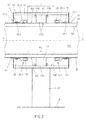
- Figures 1-4 represent a tubular diffuser TD which comprises the following features:
- Each tubular body 10 features a plurality of ports 10P, each of which extends from the inner hollow space 10H outwardly and through the wall of the tubular body 10.
- Three tubular, perforated and elastic membranes 20, each of a length of approximately 3 meters, are positioned over and in contact with the tubular body 10 and in spaced relationship to each other in a direction of the central longitudinal axis A.
- Figure 2 displays this distance d between adjacent membranes 20.
- Each membrane 20 has two opposed end zones 20.1, 20.2 with corresponding free ends 22.1, 22.2 and one central zone 24 in between.
- Each membrane 20 is fastened at both of its end zones 20.1, 20.2 to the tubular body 10 by fixing means 30, namely hose clamps, which hose clamps 30 are arranged at a distance to the respective free ends 22.1, 22.2 of the membrane 20, thereby defining two terminal sectors 26.1, 26.2 of the membrane 20 between the corresponding fixing means 30 and the free ends 22.1, 22.2.
- Both terminal sectors 26.1, 26.2 of each membrane 20 are folded oppositely to each other in a manner to overlap the hose clamp 30 of the corresponding end zone 20.1, 20.2 and to provide two end sections 28.1, 28.2 lying onto a further part of the membrane 20.
- Each membrane 20 is fastened to the tubular body 10 at a distance to its free ends 22.1, 22.2 to allow correspondingly defined terminal sectors 26.1, 26.2 to be folded and to overlap the clamps 30 and thus to protect the clamps 30 against the environment and thus against corrosion.
- the end zones 20.1, 20.2 of the membrane 30 are not perforated to avoid any ingress of liquid into the space defined by the overlapping terminal sectors 26.1, 26.2 and thus to avoid any contact of the clamps arranged in said space with the environment.
- the two end sections 28.1, 28.2 are further fastened (pressed against the central zone 24 and the tubular body 10 by corresponding hose clamps 32.
- a PTFE sliding ring 40 is arranged with its inner cylindrical surface 405 touching the outer surface 105 of the tubular body 10, which is membrane-free.
- the inner surface 40S may be concave (see dotted line in Fig. 2 )
- the outer surface 40E of said sliding ring 40 touches an inner cylindrical surface 501 of a bracket 50 and is arranged between two ribs 50R, radially protruding from said surface 50! of the bracket 50.
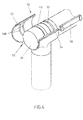
- the bracket 50 is ring-shaped and made of two half shells 52, 54 with one hinge 56 ( Fig. 4 ) in between and means 58 (a latch, not displayed in detail) for locking the bracket 50 when the two half shells 52, 54 are in a closed position and commonly form a closed ring ( Figures 2 , 3 ).
- the bracket 50 is part of a support member SP and followed by a leg 60 which is fastened to a bottom B of a treatment vessel, for example an oxidation basin for the after treatment of a seawater based absorbent used in a gas scrubber to purify a flute gas from a power plant.
- a treatment vessel for example an oxidation basin for the after treatment of a seawater based absorbent used in a gas scrubber to purify a flute gas from a power plant.
- the provision of the sliding ring 40 around a membrane free section of the tubular body 10 allows a movement of the tubular body 10 in an axial direction (longitudinal direction) A-A of the tubular diffuser TD because of a low friction between the inner ring surface 40S and the outer surface 10S of the tubular body 10, while the sliding ring 40 itself remains at its place (secured by said ribs 50R), as the support SP does.
- tubular diffuser TD Insofar the position of tubular diffuser TD remains substantially constant, while axial movements can be compensated by said support SPs.
- Figure 3 displays the free end of a tubular diffuser TD with a cap 10C, closing its free end.
- the aeration system allows a further optimization with respect to the connection between these diffusor pipes and an associated header pipe.
- tubular diffusors TD (of diameter x) are fitted to one header pipe HP of diameter X, with X>>x. While the much bigger header pipe is typically made of a GRP material the tubular diffusors of the required length will often be made of a cheaper material like polypropylene (PP), thereby causing the problem of laminating one to the other.
- PP polypropylene
- the textile may be a net (german: Gewebe) , a web (german: Gewebe), a roving /german: Roving), a stich bonded fabric (german: Gewirk) or a knitted fabric (german: Gestrick), either as such or applied onto a basic sheet (film), which sheet is then the side facing the pipe surface. This allows to heat up the sheet and to bond the textile via the sheet to said original diffusor surface.
- This pre-treated diffusor pipes may be laminated in a further treatment step to the header pipe, in particular into corresponding holes (openings) of the GRP header pipe.
- This can be done in a conventional manner, for example by using an epoxy resin or vinyl ester resin as joining element/putty.
Landscapes
- Engineering & Computer Science (AREA)
- Chemical & Material Sciences (AREA)
- Chemical Kinetics & Catalysis (AREA)
- Life Sciences & Earth Sciences (AREA)
- Mechanical Engineering (AREA)
- General Engineering & Computer Science (AREA)
- Organic Chemistry (AREA)
- Hydrology & Water Resources (AREA)
- Environmental & Geological Engineering (AREA)
- Water Supply & Treatment (AREA)
- Oil, Petroleum & Natural Gas (AREA)
- General Chemical & Material Sciences (AREA)
- Analytical Chemistry (AREA)
- Biodiversity & Conservation Biology (AREA)
- Microbiology (AREA)
- Aeration Devices For Treatment Of Activated Polluted Sludge (AREA)
- Treating Waste Gases (AREA)
Priority Applications (7)
| Application Number | Priority Date | Filing Date | Title |
|---|---|---|---|
| EP16188080.2A EP3293153B1 (de) | 2016-09-09 | 2016-09-09 | A seawater aeration system |
| CN201780028558.2A CN109071289B (zh) | 2016-09-09 | 2017-07-31 | 海水曝气系统 |
| PCT/EP2017/069302 WO2018046184A1 (en) | 2016-09-09 | 2017-07-31 | A seawater aeration system |
| MYPI2018703767A MY195205A (en) | 2016-09-09 | 2017-07-31 | A Seawater Aeration System |
| US16/315,276 US10919004B2 (en) | 2016-09-09 | 2017-07-31 | Seawater aeration system |
| KR1020187031661A KR102205297B1 (ko) | 2016-09-09 | 2017-07-31 | 해수 기폭 시스템 |
| PH12018502180A PH12018502180A1 (en) | 2016-09-09 | 2018-10-11 | A seawater aeration system |
Applications Claiming Priority (1)
| Application Number | Priority Date | Filing Date | Title |
|---|---|---|---|
| EP16188080.2A EP3293153B1 (de) | 2016-09-09 | 2016-09-09 | A seawater aeration system |
Publications (2)
| Publication Number | Publication Date |
|---|---|
| EP3293153A1 true EP3293153A1 (de) | 2018-03-14 |
| EP3293153B1 EP3293153B1 (de) | 2021-10-13 |
Family
ID=56990231
Family Applications (1)
| Application Number | Title | Priority Date | Filing Date |
|---|---|---|---|
| EP16188080.2A Not-in-force EP3293153B1 (de) | 2016-09-09 | 2016-09-09 | A seawater aeration system |
Country Status (7)
| Country | Link |
|---|---|
| US (1) | US10919004B2 (de) |
| EP (1) | EP3293153B1 (de) |
| KR (1) | KR102205297B1 (de) |
| CN (1) | CN109071289B (de) |
| MY (1) | MY195205A (de) |
| PH (1) | PH12018502180A1 (de) |
| WO (1) | WO2018046184A1 (de) |
Families Citing this family (1)
| Publication number | Priority date | Publication date | Assignee | Title |
|---|---|---|---|---|
| USD1015481S1 (en) | 2022-01-06 | 2024-02-20 | Wholesale Septic Supplies, LLC | Articulating diffuser |
Citations (7)
| Publication number | Priority date | Publication date | Assignee | Title |
|---|---|---|---|---|
| US20030071377A1 (en) * | 2001-10-12 | 2003-04-17 | Tharp Charles E. | Air diffuser membrane treated with biocide |
| US20040124550A1 (en) * | 2002-08-13 | 2004-07-01 | Itt Manufacturing Enterprises, Inc. | Strip diffuser |
| US20070013089A1 (en) * | 2004-10-26 | 2007-01-18 | Kunihiko Sasajima | Aeration device and aeration system |
| US20120061862A1 (en) * | 2010-09-10 | 2012-03-15 | Tharp Charles E | Modular diffuser body and aeration system |
| US20120187050A1 (en) * | 2011-01-21 | 2012-07-26 | Keisuke Sonoda | Aeration apparatus, seawater flue gas desulphurization apparatus including the same, and operation method of aeration apparatus |
| EP2100657B1 (de) | 2006-12-23 | 2013-01-23 | Doosan Lentjes GmbH | Rauchgasreinigungsvorrichtung |
| US20140070433A1 (en) * | 2012-09-10 | 2014-03-13 | Alexander Ott | Standpipe arrangement and fastening for holding and for supplying gas to aerators in a waste water clarifying basin |
Family Cites Families (5)
| Publication number | Priority date | Publication date | Assignee | Title |
|---|---|---|---|---|
| US5013493A (en) * | 1990-01-22 | 1991-05-07 | Environmental Dynamics, Inc. | Staggered diffuser arrangement for waste water treatment systems |
| EA000003B1 (ru) | 1996-03-12 | 1997-09-30 | Товарищество С Ограниченной Ответственностью "Экополимер" | Аэрирующее устройство |
| US7789434B2 (en) * | 2006-12-01 | 2010-09-07 | Victaulic Company | Coupling with concave bearing surface |
| KR100778491B1 (ko) * | 2006-12-29 | 2007-11-28 | 주식회사 케이엠에스 | 폭기용 산기관 |
| JP5366785B2 (ja) * | 2009-12-17 | 2013-12-11 | 株式会社クボタ | 散気管 |
-
2016
- 2016-09-09 EP EP16188080.2A patent/EP3293153B1/de not_active Not-in-force
-
2017
- 2017-07-31 KR KR1020187031661A patent/KR102205297B1/ko not_active Expired - Fee Related
- 2017-07-31 MY MYPI2018703767A patent/MY195205A/en unknown
- 2017-07-31 CN CN201780028558.2A patent/CN109071289B/zh not_active Expired - Fee Related
- 2017-07-31 US US16/315,276 patent/US10919004B2/en not_active Expired - Fee Related
- 2017-07-31 WO PCT/EP2017/069302 patent/WO2018046184A1/en not_active Ceased
-
2018
- 2018-10-11 PH PH12018502180A patent/PH12018502180A1/en unknown
Patent Citations (7)
| Publication number | Priority date | Publication date | Assignee | Title |
|---|---|---|---|---|
| US20030071377A1 (en) * | 2001-10-12 | 2003-04-17 | Tharp Charles E. | Air diffuser membrane treated with biocide |
| US20040124550A1 (en) * | 2002-08-13 | 2004-07-01 | Itt Manufacturing Enterprises, Inc. | Strip diffuser |
| US20070013089A1 (en) * | 2004-10-26 | 2007-01-18 | Kunihiko Sasajima | Aeration device and aeration system |
| EP2100657B1 (de) | 2006-12-23 | 2013-01-23 | Doosan Lentjes GmbH | Rauchgasreinigungsvorrichtung |
| US20120061862A1 (en) * | 2010-09-10 | 2012-03-15 | Tharp Charles E | Modular diffuser body and aeration system |
| US20120187050A1 (en) * | 2011-01-21 | 2012-07-26 | Keisuke Sonoda | Aeration apparatus, seawater flue gas desulphurization apparatus including the same, and operation method of aeration apparatus |
| US20140070433A1 (en) * | 2012-09-10 | 2014-03-13 | Alexander Ott | Standpipe arrangement and fastening for holding and for supplying gas to aerators in a waste water clarifying basin |
Also Published As
| Publication number | Publication date |
|---|---|
| MY195205A (en) | 2023-01-11 |
| WO2018046184A9 (en) | 2018-06-07 |
| US20190308143A1 (en) | 2019-10-10 |
| CN109071289A (zh) | 2018-12-21 |
| PH12018502180A1 (en) | 2019-10-07 |
| CN109071289B (zh) | 2021-05-11 |
| US10919004B2 (en) | 2021-02-16 |
| KR20190006170A (ko) | 2019-01-17 |
| KR102205297B1 (ko) | 2021-01-21 |
| EP3293153B1 (de) | 2021-10-13 |
| WO2018046184A1 (en) | 2018-03-15 |
Similar Documents
| Publication | Publication Date | Title |
|---|---|---|
| US8931763B2 (en) | Modular diffuser body and aeration system | |
| US20160131289A1 (en) | Telescoping pipe coupling | |
| JP6713985B2 (ja) | エアレーション部材用アセンブリーブラケットおよび取り付けシステム | |
| KR102348718B1 (ko) | 액체의 가스화를 위한 폭기 요소 | |
| US11079058B2 (en) | Stent with coiled spring | |
| KR101006355B1 (ko) | 벨로우즈형 신축밸브 | |
| JPH06213134A (ja) | 流体力学的動力発生装置 | |
| EP2101099B1 (de) | Sicherheitsspleißsystem für ausgerichtete Rohre gegen Ausdehnung bzw. Zusammenziehung | |
| US6604549B2 (en) | Device for fixing a tubular element in an inaccessible cavity | |
| RU2007113816A (ru) | Устройство герметичного перекрытия, используемое для закупорки скважины или трубопровода | |
| EP3293153B1 (de) | A seawater aeration system | |
| MX2011009998A (es) | Revestimiento protector para un tubo flexible. | |
| US5002317A (en) | Internal expansion coupling device | |
| US7887260B2 (en) | Apparatus for positioning and damping tubes or pipelines | |
| DK0668466T3 (da) | Bælg til forbindelse af rør eller apparater, som fungerer under vakuum | |
| HK1260869A1 (en) | A seawater aeration system | |
| HK1260869B (zh) | 海水曝气系统 | |
| KR200415424Y1 (ko) | 테프론 소재를 주름성형 가공하여 제작한 신축성 및내식성이 강화된 벨로우즈 신축관 | |
| US5758903A (en) | Adjustment device for adjusting a mounting device between two flanges of a pipeline system | |
| FI116201B (fi) | Letku juoksevien väliaineiden ilmastusta varten | |
| KR100647525B1 (ko) | 하수관 연결용 엘보 | |
| RU15502U1 (ru) | Стеклопластиковая труба | |
| JP2005155806A (ja) | 可撓性排水管 | |
| PL71355Y1 (pl) | Kompensator teflonowy próżniowy | |
| JPH08277967A (ja) | 軟質管の支持・継手構造および支持・接続方法 |
Legal Events
| Date | Code | Title | Description |
|---|---|---|---|
| PUAI | Public reference made under article 153(3) epc to a published international application that has entered the european phase |
Free format text: ORIGINAL CODE: 0009012 |
|
| STAA | Information on the status of an ep patent application or granted ep patent |
Free format text: STATUS: REQUEST FOR EXAMINATION WAS MADE |
|
| 17P | Request for examination filed |
Effective date: 20170814 |
|
| AK | Designated contracting states |
Kind code of ref document: A1 Designated state(s): AL AT BE BG CH CY CZ DE DK EE ES FI FR GB GR HR HU IE IS IT LI LT LU LV MC MK MT NL NO PL PT RO RS SE SI SK SM TR |
|
| AX | Request for extension of the european patent |
Extension state: BA ME |
|
| STAA | Information on the status of an ep patent application or granted ep patent |
Free format text: STATUS: EXAMINATION IS IN PROGRESS |
|
| 17Q | First examination report despatched |
Effective date: 20190613 |
|
| GRAP | Despatch of communication of intention to grant a patent |
Free format text: ORIGINAL CODE: EPIDOSNIGR1 |
|
| STAA | Information on the status of an ep patent application or granted ep patent |
Free format text: STATUS: GRANT OF PATENT IS INTENDED |
|
| INTG | Intention to grant announced |
Effective date: 20210531 |
|
| GRAS | Grant fee paid |
Free format text: ORIGINAL CODE: EPIDOSNIGR3 |
|
| GRAA | (expected) grant |
Free format text: ORIGINAL CODE: 0009210 |
|
| STAA | Information on the status of an ep patent application or granted ep patent |
Free format text: STATUS: THE PATENT HAS BEEN GRANTED |
|
| AK | Designated contracting states |
Kind code of ref document: B1 Designated state(s): AL AT BE BG CH CY CZ DE DK EE ES FI FR GB GR HR HU IE IS IT LI LT LU LV MC MK MT NL NO PL PT RO RS SE SI SK SM TR |
|
| REG | Reference to a national code |
Ref country code: GB Ref legal event code: FG4D |
|
| REG | Reference to a national code |
Ref country code: CH Ref legal event code: EP |
|
| REG | Reference to a national code |
Ref country code: DE Ref legal event code: R096 Ref document number: 602016064828 Country of ref document: DE |
|
| REG | Reference to a national code |
Ref country code: IE Ref legal event code: FG4D |
|
| REG | Reference to a national code |
Ref country code: AT Ref legal event code: REF Ref document number: 1438087 Country of ref document: AT Kind code of ref document: T Effective date: 20211115 |
|
| REG | Reference to a national code |
Ref country code: LT Ref legal event code: MG9D |
|
| REG | Reference to a national code |
Ref country code: NL Ref legal event code: MP Effective date: 20211013 |
|
| PG25 | Lapsed in a contracting state [announced via postgrant information from national office to epo] |
Ref country code: RS Free format text: LAPSE BECAUSE OF FAILURE TO SUBMIT A TRANSLATION OF THE DESCRIPTION OR TO PAY THE FEE WITHIN THE PRESCRIBED TIME-LIMIT Effective date: 20211013 Ref country code: LT Free format text: LAPSE BECAUSE OF FAILURE TO SUBMIT A TRANSLATION OF THE DESCRIPTION OR TO PAY THE FEE WITHIN THE PRESCRIBED TIME-LIMIT Effective date: 20211013 Ref country code: FI Free format text: LAPSE BECAUSE OF FAILURE TO SUBMIT A TRANSLATION OF THE DESCRIPTION OR TO PAY THE FEE WITHIN THE PRESCRIBED TIME-LIMIT Effective date: 20211013 Ref country code: BG Free format text: LAPSE BECAUSE OF FAILURE TO SUBMIT A TRANSLATION OF THE DESCRIPTION OR TO PAY THE FEE WITHIN THE PRESCRIBED TIME-LIMIT Effective date: 20220113 |
|
| PG25 | Lapsed in a contracting state [announced via postgrant information from national office to epo] |
Ref country code: IS Free format text: LAPSE BECAUSE OF FAILURE TO SUBMIT A TRANSLATION OF THE DESCRIPTION OR TO PAY THE FEE WITHIN THE PRESCRIBED TIME-LIMIT Effective date: 20220213 Ref country code: SE Free format text: LAPSE BECAUSE OF FAILURE TO SUBMIT A TRANSLATION OF THE DESCRIPTION OR TO PAY THE FEE WITHIN THE PRESCRIBED TIME-LIMIT Effective date: 20211013 Ref country code: PT Free format text: LAPSE BECAUSE OF FAILURE TO SUBMIT A TRANSLATION OF THE DESCRIPTION OR TO PAY THE FEE WITHIN THE PRESCRIBED TIME-LIMIT Effective date: 20220214 Ref country code: PL Free format text: LAPSE BECAUSE OF FAILURE TO SUBMIT A TRANSLATION OF THE DESCRIPTION OR TO PAY THE FEE WITHIN THE PRESCRIBED TIME-LIMIT Effective date: 20211013 Ref country code: NO Free format text: LAPSE BECAUSE OF FAILURE TO SUBMIT A TRANSLATION OF THE DESCRIPTION OR TO PAY THE FEE WITHIN THE PRESCRIBED TIME-LIMIT Effective date: 20220113 Ref country code: NL Free format text: LAPSE BECAUSE OF FAILURE TO SUBMIT A TRANSLATION OF THE DESCRIPTION OR TO PAY THE FEE WITHIN THE PRESCRIBED TIME-LIMIT Effective date: 20211013 Ref country code: LV Free format text: LAPSE BECAUSE OF FAILURE TO SUBMIT A TRANSLATION OF THE DESCRIPTION OR TO PAY THE FEE WITHIN THE PRESCRIBED TIME-LIMIT Effective date: 20211013 Ref country code: HR Free format text: LAPSE BECAUSE OF FAILURE TO SUBMIT A TRANSLATION OF THE DESCRIPTION OR TO PAY THE FEE WITHIN THE PRESCRIBED TIME-LIMIT Effective date: 20211013 Ref country code: GR Free format text: LAPSE BECAUSE OF FAILURE TO SUBMIT A TRANSLATION OF THE DESCRIPTION OR TO PAY THE FEE WITHIN THE PRESCRIBED TIME-LIMIT Effective date: 20220114 Ref country code: ES Free format text: LAPSE BECAUSE OF FAILURE TO SUBMIT A TRANSLATION OF THE DESCRIPTION OR TO PAY THE FEE WITHIN THE PRESCRIBED TIME-LIMIT Effective date: 20211013 |
|
| REG | Reference to a national code |
Ref country code: DE Ref legal event code: R097 Ref document number: 602016064828 Country of ref document: DE |
|
| PG25 | Lapsed in a contracting state [announced via postgrant information from national office to epo] |
Ref country code: SM Free format text: LAPSE BECAUSE OF FAILURE TO SUBMIT A TRANSLATION OF THE DESCRIPTION OR TO PAY THE FEE WITHIN THE PRESCRIBED TIME-LIMIT Effective date: 20211013 Ref country code: SK Free format text: LAPSE BECAUSE OF FAILURE TO SUBMIT A TRANSLATION OF THE DESCRIPTION OR TO PAY THE FEE WITHIN THE PRESCRIBED TIME-LIMIT Effective date: 20211013 Ref country code: RO Free format text: LAPSE BECAUSE OF FAILURE TO SUBMIT A TRANSLATION OF THE DESCRIPTION OR TO PAY THE FEE WITHIN THE PRESCRIBED TIME-LIMIT Effective date: 20211013 Ref country code: EE Free format text: LAPSE BECAUSE OF FAILURE TO SUBMIT A TRANSLATION OF THE DESCRIPTION OR TO PAY THE FEE WITHIN THE PRESCRIBED TIME-LIMIT Effective date: 20211013 Ref country code: DK Free format text: LAPSE BECAUSE OF FAILURE TO SUBMIT A TRANSLATION OF THE DESCRIPTION OR TO PAY THE FEE WITHIN THE PRESCRIBED TIME-LIMIT Effective date: 20211013 Ref country code: CZ Free format text: LAPSE BECAUSE OF FAILURE TO SUBMIT A TRANSLATION OF THE DESCRIPTION OR TO PAY THE FEE WITHIN THE PRESCRIBED TIME-LIMIT Effective date: 20211013 |
|
| PLBE | No opposition filed within time limit |
Free format text: ORIGINAL CODE: 0009261 |
|
| STAA | Information on the status of an ep patent application or granted ep patent |
Free format text: STATUS: NO OPPOSITION FILED WITHIN TIME LIMIT |
|
| 26N | No opposition filed |
Effective date: 20220714 |
|
| PG25 | Lapsed in a contracting state [announced via postgrant information from national office to epo] |
Ref country code: AL Free format text: LAPSE BECAUSE OF FAILURE TO SUBMIT A TRANSLATION OF THE DESCRIPTION OR TO PAY THE FEE WITHIN THE PRESCRIBED TIME-LIMIT Effective date: 20211013 |
|
| PG25 | Lapsed in a contracting state [announced via postgrant information from national office to epo] |
Ref country code: SI Free format text: LAPSE BECAUSE OF FAILURE TO SUBMIT A TRANSLATION OF THE DESCRIPTION OR TO PAY THE FEE WITHIN THE PRESCRIBED TIME-LIMIT Effective date: 20211013 |
|
| REG | Reference to a national code |
Ref country code: DE Ref legal event code: R119 Ref document number: 602016064828 Country of ref document: DE |
|
| PG25 | Lapsed in a contracting state [announced via postgrant information from national office to epo] |
Ref country code: MC Free format text: LAPSE BECAUSE OF FAILURE TO SUBMIT A TRANSLATION OF THE DESCRIPTION OR TO PAY THE FEE WITHIN THE PRESCRIBED TIME-LIMIT Effective date: 20211013 |
|
| REG | Reference to a national code |
Ref country code: CH Ref legal event code: PL |
|
| GBPC | Gb: european patent ceased through non-payment of renewal fee |
Effective date: 20220909 |
|
| REG | Reference to a national code |
Ref country code: BE Ref legal event code: MM Effective date: 20220930 |
|
| PG25 | Lapsed in a contracting state [announced via postgrant information from national office to epo] |
Ref country code: IT Free format text: LAPSE BECAUSE OF FAILURE TO SUBMIT A TRANSLATION OF THE DESCRIPTION OR TO PAY THE FEE WITHIN THE PRESCRIBED TIME-LIMIT Effective date: 20211013 |
|
| PG25 | Lapsed in a contracting state [announced via postgrant information from national office to epo] |
Ref country code: LU Free format text: LAPSE BECAUSE OF NON-PAYMENT OF DUE FEES Effective date: 20220909 |
|
| PG25 | Lapsed in a contracting state [announced via postgrant information from national office to epo] |
Ref country code: LI Free format text: LAPSE BECAUSE OF NON-PAYMENT OF DUE FEES Effective date: 20220930 Ref country code: IE Free format text: LAPSE BECAUSE OF NON-PAYMENT OF DUE FEES Effective date: 20220909 Ref country code: FR Free format text: LAPSE BECAUSE OF NON-PAYMENT OF DUE FEES Effective date: 20220930 Ref country code: DE Free format text: LAPSE BECAUSE OF NON-PAYMENT OF DUE FEES Effective date: 20230401 Ref country code: CH Free format text: LAPSE BECAUSE OF NON-PAYMENT OF DUE FEES Effective date: 20220930 |
|
| PG25 | Lapsed in a contracting state [announced via postgrant information from national office to epo] |
Ref country code: BE Free format text: LAPSE BECAUSE OF NON-PAYMENT OF DUE FEES Effective date: 20220930 |
|
| PG25 | Lapsed in a contracting state [announced via postgrant information from national office to epo] |
Ref country code: GB Free format text: LAPSE BECAUSE OF NON-PAYMENT OF DUE FEES Effective date: 20220909 |
|
| REG | Reference to a national code |
Ref country code: AT Ref legal event code: MM01 Ref document number: 1438087 Country of ref document: AT Kind code of ref document: T Effective date: 20220909 |
|
| PG25 | Lapsed in a contracting state [announced via postgrant information from national office to epo] |
Ref country code: AT Free format text: LAPSE BECAUSE OF NON-PAYMENT OF DUE FEES Effective date: 20220909 |
|
| PG25 | Lapsed in a contracting state [announced via postgrant information from national office to epo] |
Ref country code: HU Free format text: LAPSE BECAUSE OF FAILURE TO SUBMIT A TRANSLATION OF THE DESCRIPTION OR TO PAY THE FEE WITHIN THE PRESCRIBED TIME-LIMIT; INVALID AB INITIO Effective date: 20160909 |
|
| PG25 | Lapsed in a contracting state [announced via postgrant information from national office to epo] |
Ref country code: CY Free format text: LAPSE BECAUSE OF FAILURE TO SUBMIT A TRANSLATION OF THE DESCRIPTION OR TO PAY THE FEE WITHIN THE PRESCRIBED TIME-LIMIT Effective date: 20211013 |
|
| PG25 | Lapsed in a contracting state [announced via postgrant information from national office to epo] |
Ref country code: MK Free format text: LAPSE BECAUSE OF FAILURE TO SUBMIT A TRANSLATION OF THE DESCRIPTION OR TO PAY THE FEE WITHIN THE PRESCRIBED TIME-LIMIT Effective date: 20211013 |
|
| PG25 | Lapsed in a contracting state [announced via postgrant information from national office to epo] |
Ref country code: TR Free format text: LAPSE BECAUSE OF FAILURE TO SUBMIT A TRANSLATION OF THE DESCRIPTION OR TO PAY THE FEE WITHIN THE PRESCRIBED TIME-LIMIT Effective date: 20211013 |
|
| PG25 | Lapsed in a contracting state [announced via postgrant information from national office to epo] |
Ref country code: MT Free format text: LAPSE BECAUSE OF FAILURE TO SUBMIT A TRANSLATION OF THE DESCRIPTION OR TO PAY THE FEE WITHIN THE PRESCRIBED TIME-LIMIT Effective date: 20211013 |